Gas Turbine Cycle with External Combustion Chamber for Prosumer and Distributed Energy Systems

 , ,
, ,  ,
,  and
and 
Abstract
1. Introduction
2. Materials and Methods
2.1. Nomentclature and Units
2.2. The Computation Algorithm
3. Results
- applying lower compressor efficiency equal to 0.75 (instead 0.80) we observe the drop of overall efficiency by about 7%–8% for all considered variants while assuming higher compressor efficiency 0.85 the increase in overall efficiency can reach 6.5%–7.5%,
- decreasing turbine efficiency from 0.82 to 0.77 we lower the overall efficiency by about 9%–10% and increasing it to 0.87 we have the rise in overall efficiency by about 8%–9%,
- changing the combustion chamber efficiency by 5% the overall efficiency also changes by about 5%,
- assuming high values of all elements (compressor efficiency −0.85, turbine efficiency −0.87, combustion chamber efficiency −0.985, regenerator efficiency 0.98) we may increase the overall power plant efficiency by 18%–21%,
- using low values of all elements (compressor efficiency −0.75, turbine efficiency −0.77, combustion chamber efficiency −0.9, regenerator efficiency 0.8) we may reduce the overall power plant efficiency by 28%–32%.
4. Final Conclusions
- Systems with an external combustion chamber and air intake from behind the turbine can be competitive in terms of efficiency with classic turbine sets, also those with regeneration.
- The use of fuels with lower calorific value usually leads to a lower efficiency of the power plant.
- The structure of the gas turbine power plant and the type of fuel should be taken into account at the stage of determining the main design parameters of the turbine set (e.g., optimal compression ratio, unit power).
- Turbosets with an external combustion chamber and air intake from behind the turbine are characterized by wide possibilities of applications in cogeneration systems and high efficiency combined systems.
Author Contributions
Funding
Conflicts of Interest
References
- Maczynska, J.; Krzywonos, M.; Kupczyk, A.; Tucki, K.; Sikora, M.; Pinkowska, H.; Baczyk, A.; Wielewska, I. Production and use of biofuels for transport in Poland and Brazil. The case of bioethanol. Fuel 2019, 241, 989–996. [Google Scholar] [CrossRef]
- Tucki, K.; Mruk, M.; Orynycz, O.; Botwinska, K.; Gola, A. Toxicity of Exhaust Fumes (CO, NOx) of the Compression-Ignition (Diesel) Engine with the Use of Simulation. Sustainability 2019, 11, 2188. [Google Scholar] [CrossRef]
- Tucki, K.; Mruk, R.; Orynycz, O.; Wasiak, A.; Botwinska, K.; Gola, A. Simulation of the Operation of a Spark Ignition Engine Fueled with Various Biofuels and Its Contribution to Technology Management. Sustainability 2019, 11, 2799. [Google Scholar] [CrossRef]
- Braungardt, S.; Bürger, V.; Zieger, J.; Bosselaar, L. How to include cooling in the EU Renewable Energy Directive? Strategies and policy implications. Energy Policy 2019, 129, 260–267. [Google Scholar] [CrossRef]
- Veum, K.; Bauknecht, D. How to reach the EU renewables target by 2030? An analysis of the governance framework. Energy Policy 2019, 127, 299–307. [Google Scholar] [CrossRef]
- Gökgöz, F.; Güvercin, M.T. Energy security and renewable energy efficiency in EU. Renew. Sustain. Energy Rev. 2018, 96, 226–239. [Google Scholar] [CrossRef]
- Xu, G.; Li, M.; Lu, P. Experimental investigation on flow properties of different biomass and torrefied biomass powders. Biomass Bioenergy 2019, 122, 63–75. [Google Scholar] [CrossRef]
- Goffé, J.; Ferrasse, J.H. Stoichiometry impact on the optimum efficiency of biomass conversion to biofuels. Energy 2019, 170, 438–458. [Google Scholar]
- Tucki, K.; Orynycz, O.; Wasiak, A.; Swic, A.; Wichlacz, J. The Impact of Fuel Type on the Output Parameters of a New Biofuel Burner. Energies 2019, 12, 1383. [Google Scholar] [CrossRef]
- Bunn, D.W.; Redondo-Martin, J.; Munoz-Hernandez, J.I.; Diaz-Cachinero, P. Analysis of coal conversion to biomass as a transitional technology. Renew. Energy 2019, 132, 752–760. [Google Scholar] [CrossRef]
- Hamelin, L.; Borzęcka, M.; Kozak, M.; Pudełko, R. A spatial approach to bioeconomy: Quantifying the residual biomass potential in the EU-27. Renew. Sustain. Energy Rev. 2019, 100, 127–142. [Google Scholar] [CrossRef]
- Holland, R.A.; Beaumont, N.; Hooper, T.; Austen, M.; Gross, R.J.K.; Heptonstall, P.J.; Ketsopoulou, I.; Winskel, M.; Watson, J.; Taylor, G. Incorporating ecosystem services into the design of future energy systems. Appl. Energy 2018, 222, 812–822. [Google Scholar] [CrossRef]
- Picchi, P.; Van Lierop, M.; Geneletti, D.; Stremke, S. Advancing the relationship between renewable energy and ecosystem services for landscape planning and design: A literature review. Ecosyst. Serv. 2019, 35, 241–259. [Google Scholar] [CrossRef]
- Tucki, K.; Mruk, R.; Orynycz, O.; Gola, A. The Effects of Pressure and Temperature on the Process of Auto-Ignition and Combustion of Rape Oil and Its Mixtures. Sustainability 2019, 11, 3451. [Google Scholar] [CrossRef]
- Wasiak, A.; Orynycz, O. The effects of energy contributions into subsidiary processes on energetic efficiency of biomass plantation supplying biofuel production system. Agric. Agric. Sci. Procedia 2015, 7, 292–300. [Google Scholar] [CrossRef]
- Moslehi, S.; Reddy, T.A. An LCA methodology to assess location-specific environmental externalities of integrated energy systems. Sustain. Cities Soc. 2019, 46, 1–14. [Google Scholar] [CrossRef]
- Kupczyk, A.; Maczynska, J.; Redlarski, G.; Tucki, K.; Baczyk, A.; Rutkowski, D. Selected Aspects of Biofuels Market and the Electromobility Development in Poland: Current Trends and Forecasting Changes. Appl. Sci. 2019, 9, 254. [Google Scholar] [CrossRef]
- Kosowski, K.; Tucki, K.; Kosowski, A. Application of Artificial Neural Networks in Investigations of Steam Turbine Cascades. J. Turbomach. Trans. ASME 2010, 132, 014501–014505. [Google Scholar] [CrossRef]
- Kosowski, K.; Tucki, K.; Kosowski, A. Turbine stage design aided by artificial intelligence methods. Expert Syst. Appl. 2009, 36, 11536–11542. [Google Scholar] [CrossRef]
- IEO Report PV Market in Poland 2019. Available online: www.ieo.en/ (accessed on 17 July 2019).
- Tucki, K.; Orynycz, O.; Wasiak, A.; Świć, A.; Dybaś, W. Capacity market implementation in Poland: Analysis of a survey on consequences for the electricity market and for energy management. Energies 2019, 12, 839. [Google Scholar] [CrossRef]
- Baatz, B.; Relf, G.; Nowak, S. The role of energy efficiency in a distributed energy future. Electr. J. 2018, 31, 13–16. [Google Scholar] [CrossRef]
- Puri, S.; Perera, A.T.D.; Mauree, D.; Coccolo, S.; Delannoy, L.; Scartezzini, J.L. The role of distributed energy systems in European energy transition. Energy Procedia 2019, 159, 286–291. [Google Scholar] [CrossRef]
- Calise, F.; De Notaristefani di Vastogirardi, G.; D’Accadia, M.D.; Vicidomini, M. Simulation of polygeneration systems. Energy 2018, 163, 290–337. [Google Scholar] [CrossRef]
- Jarnut, M.; Wermiński, S.; Waśkowicz, B. Comparative analysis of selected energy storage technologies for prosumer-owned microgrids. Renew. Sustain. Energy Rev. 2017, 74, 925–937. [Google Scholar] [CrossRef]
- Aiying, R.; Risto, L. Role of polygeneration in sustainable energy system development: Challenges and opportunities from optimization viewpoints. Renew. Sustain. Energy Rev. 2016, 53, 363–372. [Google Scholar]
- Kosowski, K.; Domachowski, Z.; Próchnicki, W.; Kosowski, A.; Stępień, R.; Piwowarski, M.; Włodarski, W.; Ghaemi, M.; Tucki, K.; Gardzilewicz, A.; et al. Steam and Gas Turbines with the Examples of Alstom Technology, 1st ed.; Alstom: Saint-Quen, France, 2007; ISBN 978-83-925959-3-9. [Google Scholar]
- Krzywonos, M.; Tucki, K.; Wojdalski, J.; Kupczyk, A.; Sikora, M. Analysis of Properties of Synthetic Hydrocarbons Produced Using the ETG Method and Selected Conventional Biofuels Made in Poland in the Context of Environmental Effects Achieved. Rocz. Ochr. Śr. 2017, 19, 394–410. [Google Scholar]
- Tonini, D.; Hamelin, L.; Alvarado-Morales, M.; Astrup, T.F. GHG emission factors for bioelectricity, biomethane, and bioethanol quantified for 24 biomass substrates with consequential life-cycle assessment. Bioresour. Technol. 2016, 208, 123–133. [Google Scholar] [CrossRef]
- Shen, X.; Kommalapati, R.R.; Huque, Z. The Comparative Life Cycle Assessment of Power Generation from Lignocellulosic Biomass. Sustainability 2015, 7, 12974. [Google Scholar] [CrossRef]
- Carneiro, M.L.N.M.; Pradelle, F.; Braga, S.L.; Gomes, M.S.P.; Martins, M.R.F.A.; Turkovics, F.; Pradelle, R.N.C. Potential of biofuels from algae: Comparison with fossil fuels, ethanol and biodiesel in Europe and Brazil through life cycle assessment (LCA). Renew. Sustain. Energy Rev. 2017, 73, 632–653. [Google Scholar] [CrossRef]
- Adelt, M.; Wolf, D.; Vogel, A. LCA of biomethane. J. Nat. Gas Sci. Eng. 2011, 3, 646–650. [Google Scholar] [CrossRef]
- Ardolino, F.; Arena, U. Biowaste-to-Biomethane: An LCA study on biogas and syngas roads. Waste Manag. 2019, 87, 441–453. [Google Scholar] [CrossRef] [PubMed]
- Rocha, M.H.; Capaz, R.S.; Lora, E.E.S.; Nogueira, L.A.H.; Leme, M.M.V.; Renó, M.L.G.; Del Olmo, O.A. Life cycle assessment (LCA) for biofuels in Brazilian conditions: A meta-analysis. Renew. Sustain. Energy Rev. 2014, 37, 435–459. [Google Scholar] [CrossRef]
- Collotta, M.; Champagne, P.; Mabee, W.; Tomasoni, G.; Leite, G.B.; Busi, L.; Alberti, M. Comparative LCA of Flocculation for the Harvesting of Microalgae for Biofuels Production. Procedia CIRP 2017, 61, 756–760. [Google Scholar] [CrossRef]
- Milledge, J.J.; Heaven, S. Energy Balance of Biogas Production from Microalgae: Effect of Harvesting Method, Multiple Raceways, Scale of Plant and Combined Heat and Power Generation. J. Mar. Sci. Eng. 2017, 5, 9. [Google Scholar] [CrossRef]
- Gonzalez-Fernandez, C.; Sialve, B.; Bernet, N.; Steyer, J.P. Impact of microalgae characteristics on their conversion to biofuel. Part ii: Focus on biomethane production. Biofuels Bioprod. Biorefining 2012, 6, 205–218. [Google Scholar] [CrossRef]
- Igliński, B.; Iglińska, A.; Kujawski, W.; Buczkowski, R.; Cichosz, M. Bioenergy in Poland. Renew. Sustain. Energy Rev. 2011, 15, 2999–3007. [Google Scholar] [CrossRef]
- Experimental Algae to Grow at the Refinery. Available online: https://www.orlen.pl/ (accessed on 17 July 2019).
- PKN ORLEN Invests in Biofuels of the Future. Available online: https://www.orlen.pl/ (accessed on 17 July 2019).
- ORLEN Group 2017. Integrated Report. Available online: https://raportzintegrowany2017.orlen.pl/ (accessed on 17 July 2019).
- Unipetrol Enters the BIOENERGY 2020+ project. Available online: http://www.unipetrol.cz (accessed on 17 July 2019).
- Lisowski, A. Technologie Zbioru Roślin Energetycznych (Energy Plants Harvesting Technologies), 1st ed.; Wydawnictwo SGGW: Warszawa, Polska, 2010; pp. 77–119. [Google Scholar]
- Stolarski, M.J.; Niksa, D.; Krzyżaniak, M.; Tworkowski, J.; Szczukowski, S. Willow productivity from small- and large-scale experimental plantations in Poland from 2000 to 2017. Renew. Sustain. Energy Rev. 2019, 101, 461–475. [Google Scholar] [CrossRef]
- Cozzolino, R.; Lombardi, L.; Tribioli, L. Use of biogas from biowaste in a solid oxide fuel cell stack: Application to an off-grid power plant. Renew. Energy 2017, 111, 781–791. [Google Scholar] [CrossRef]
- Saadabadi, S.A.; Thattai, A.T.; Fan, L.; Lindeboom, R.E.F.; Spanjers, H.; Aravind, P.V. Solid Oxide Fuel Cells fuelled with biogas: Potential and constraints. Renew. Energy 2019, 134, 194–214. [Google Scholar] [CrossRef]
- Mikielewicz, J.; Piwowarski, M.; Kosowski, K. Design analysis of turbines for co-generating micro-power plant working in accordance with organic rankine’s cycle. Pol. Marit. Res. 2009, 1, 34–38. [Google Scholar] [CrossRef]
- Stępniak, D.; Piwowarski, M. Analyzing selection of low-temperature medium for cogeneration micro power plant. Pol. J. Environ. Stud. 2014, 23, 1417–1421. [Google Scholar]
- Tucki, K.; Sikora, M. Technical and logistics analysis of the extension of the energy supply system with the cogeneration unit supplied with biogas from the water treatment plant. TEKA of the Commission of Motorization and Power Industry in Agriculture 2016, 16, 71–75. [Google Scholar]
- Piwowarski, M.; Kosowski, K. Design analysis of combined gas-vapour micro power plant with 30 kw air turbine. Pol. J. Environ. Stud. 2014, 23, 1397–1401. [Google Scholar]
- Kosowski, K.; Tucki, K.; Piwowarski, M.; Stępień, R.; Orynycz, O.; Włodarski, W.; Bączyk, A. Thermodynamic Cycle Concepts for High-Efficiency Power Plans. Part A: Public Power Plants 60+. Sustainability 2019, 11, 554. [Google Scholar] [CrossRef]
- Giorgetti, S.; Parente, A.; Bricteux, L.; Contino, F.; De Paepe, W. Optimal design and operating strategy of a carbon-clean micro gas turbine for combined heat and power applications. International Journal of Greenhouse Gas Control 2019, 88, 469–481. [Google Scholar] [CrossRef]
- De Paepe, W.; Coppitters, D.; Abraham, S.; Tsirikoglou, P.; Ghorbaniasl, G.; Contino, F. Robust Operational Optimization of a Typical micro Gas Turbine. Energy Procedia 2019, 158, 5795–5803. [Google Scholar] [CrossRef]
- Lampart, P.; Kosowski, K.; Piwowarski, M.; Jędrzejewski, L. Design analysis of tesla micro-turbine operating on a low-boiling medium. Pol. Marit. Res. 2009, 1, 28–33. [Google Scholar] [CrossRef]
- Kabir, E.; Kumar, P.; Kumar, S.; Adelodun, A.A.; Kim, K.H. Solar energy: Potential and future prospects. Renew. Sustain. Energy Rev. 2018, 82, 894–900. [Google Scholar] [CrossRef]
- Palm, J.; Eidenskog, M.; Luthander, R. Sufficiency, change, and flexibility: Critically examining the energy consumption profiles of solar PV prosumers in Sweden. Energy Res. Soc. Sci. 2018, 39, 12–18. [Google Scholar] [CrossRef]
- Chordia, L. High temperature heat exchanger design and fabrication for systems with large pressure differentials. In Final Scientific/Technical Report 2017. Available online: www.osti.gov/servlets/purl/1349235 (accessed on 17 July 2019).
- The exceptional performance of Heatric PCHE heat exchangers. Available online: www.heatric.com/heat_exchanger_performance.html (accessed on 17 July 2019).
- Ślefarski, R.; Jójka, J.; Czyżewski, P.; Grzymisławski, P. Experimental investigation on syngas reburning process in a gaseous fuel firing semi-industrial combustion chamber. Fuel 2018, 217, 490–498. [Google Scholar] [CrossRef]
- Włodarski, W. Control of a vapour microturbine set in cogeneration applications. ISA Transa. 2019, in press. [Google Scholar] [CrossRef]
- Taler, J.; Mruk, A.; Cisek, J.; Majewski, K. Combined heat and power plant with internal combustion engine fuelled by wood gas. Rynek Energii 2013, 4, 62–67. [Google Scholar]
- Kordylewski, W. Spalanie i Paliwa, 5th ed.; Oficyna Wydawnicza Politechniki Wrocławskiej: Wrocław, Polska, 2008; pp. 10–470. ISBN 978-83-7493-378-0. [Google Scholar]
- Traupel, W. Thermische Turbomachinen, 2nd ed.; Springer: Berlin, Heidelberg; New York, NY, USA, 1982; pp. 122–525. Available online: https://link.springer.com/book/10.1007%2F978-3-642-96632-3 (accessed on 12 August 2019).
- Sawyer, J.W. Gas Turbine Engineering Handbook, 3rd ed.; Turbomachinery International Publications: Norwalk, CT, USA, 1985; pp. 98–245. ISBN 0-937506-14-1. [Google Scholar]
- Sorensen, H.A. Gas Turbines (Series in Mechanical Engineering), 1st ed.; Ronald Press Company: New York, NY, USA, 1951; pp. 48–440. [Google Scholar]
- Gailfuß, M. Private meets Public—Small Scale CHP; Technological Developments, Workshop BHKW-Infozentrum Rastatt 09.09.2003: Berlin, Germany, 2003. [Google Scholar]
- Kosowski, K.; Piwowarski, M.; Stępień, R.; Włodarski, W. Design and Investigations of a Micro-Turbine Flow Part. In Proceedings of the ASME Turbo Expo 2012: Turbine Technical Conference and Exposition; Volume 5: Manufacturing Materials and Metallurgy; Marine; Microturbines and Small Turbomachinery; Supercritical CO2 Power Cycles, Copenhagen, Denmark, 11–15 June 2012; Paper No. GT2012-69222. pp. 807–814. [Google Scholar] [CrossRef]
- Mills, D. Advances in solar thermal electricity technology. Solar Energy 2004, 76, 19–31. [Google Scholar] [CrossRef]
- Kosowski, K.; Włodarski, W.; Piwowarski, M.; Stepień, R. Performance characteristics of a micro-turbine. Adv. Vib. Eng. 2014, 2, 341–350. [Google Scholar]
- Kosowski, K.; Piwowarski, M.; Stępień, R.; Włodarski, W. Design and investigations of the ethanol microturbine. Arch. Thermodyn. 2018, 39, 41–54. [Google Scholar]


| Symbol | Description | Unit |
|---|---|---|
| specific heat at constant pressure | ||
| enthalpy of unit mass | ||
| pressure | ||
| efficiency | ||
| mass flow | ||
| work of unit mass | ||
| specific heat at constant pressure | ||
| exponent of isentropic process | ||
| power | ||
| heat flux | [kW] | |
| temperature | ||
| lower heating value | or | |
| compression ratio |
| Symbol | Description |
|---|---|
| f | fuel |
| m | mechanical |
| opt | optimal |
| meth | methane |
| C | compressor |
| CC | combustion chamber |
| T | turbine |
| GT | gas turbine set |
| 1, 2,… | points on diagrams |
| Description | Unit | Value |
|---|---|---|
| compressor efficiency | [-] | 0.800 |
| turbine efficiency | [-] | 0.820 |
| mechanical efficiency | [-] | 0.980 |
| leakage losses | [-] | 0.02 |
| generator efficiency | [-] | 0.900 |
| efficiency of the combustion chamber | [-] | 0.950 |
| pressure loss in the filter | [-] | 0.995 |
| pressure loss in the silencer | [-] | 0.995 |
| pressure losses in the combustion chamber | [-] | 0.98 |
| pressure loss in the regenerator | [-] | 0.98 |
| Fuel Type | Volumetric Composition | Density | Calorific Value, LHV |
|---|---|---|---|
| [-] | [kg/m3] | [MJ/kg] | |
| gas from biomass gasification | CH4 0.09; CO2 0.133; CO 0.147; H2 0.073; N2 0.42; H2O 0.137 | 1.2107 | 4.4 |
| biogas | CH4 0.4; CO2 0.23; H2 0.16; CO 0.1; N2 0.11 | 0.9438 | 17.5 |
| methane | CH4 1.0 | 0.6660 | 54.1 |
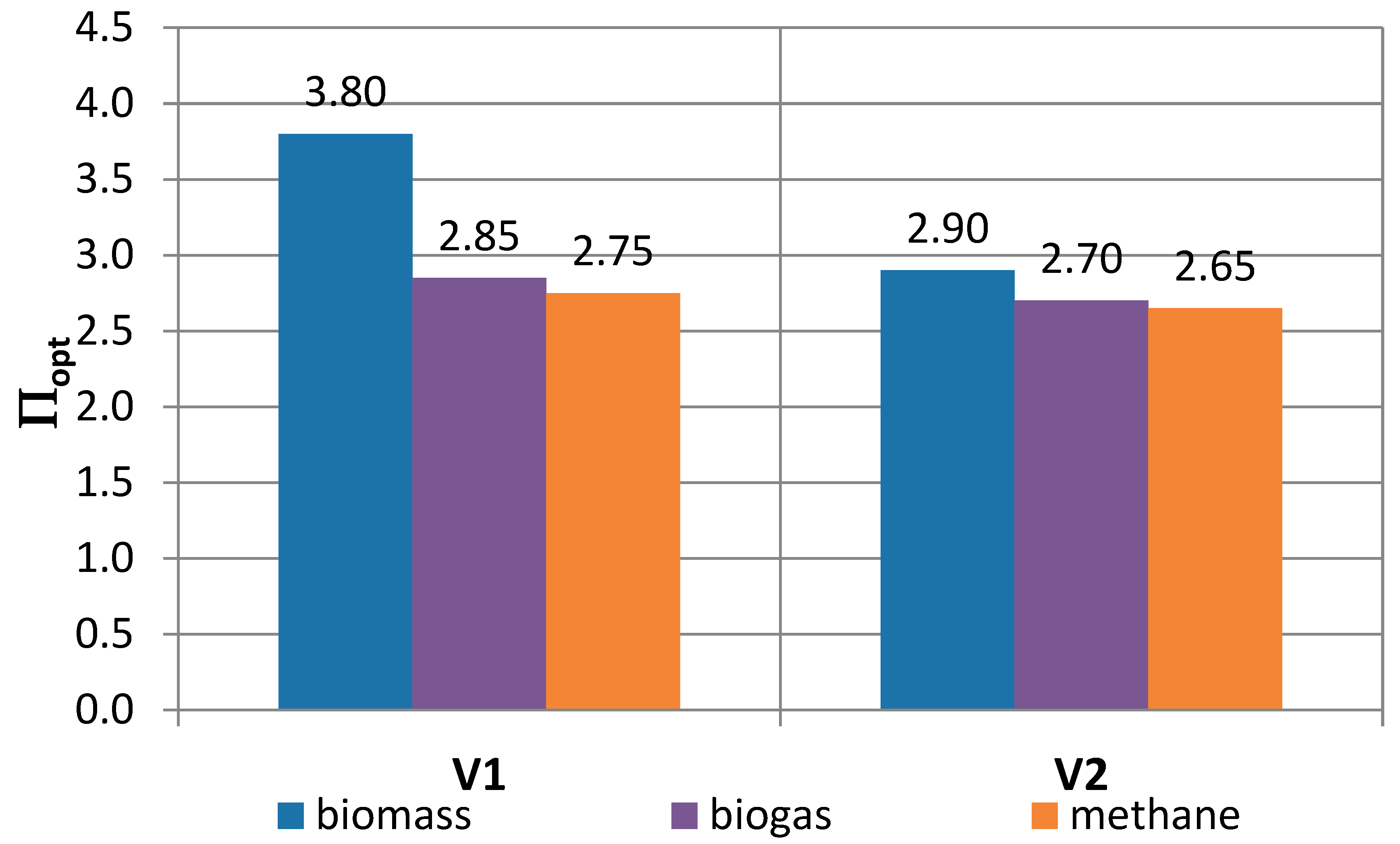
| Parameter | Variant | Biomass | Biogas | Methane |
|---|---|---|---|---|
| ∏opt | V1 | 3.80 | 2.85 | 2.75 |
| V2 | 2.90 | 2.70 | 2.65 | |
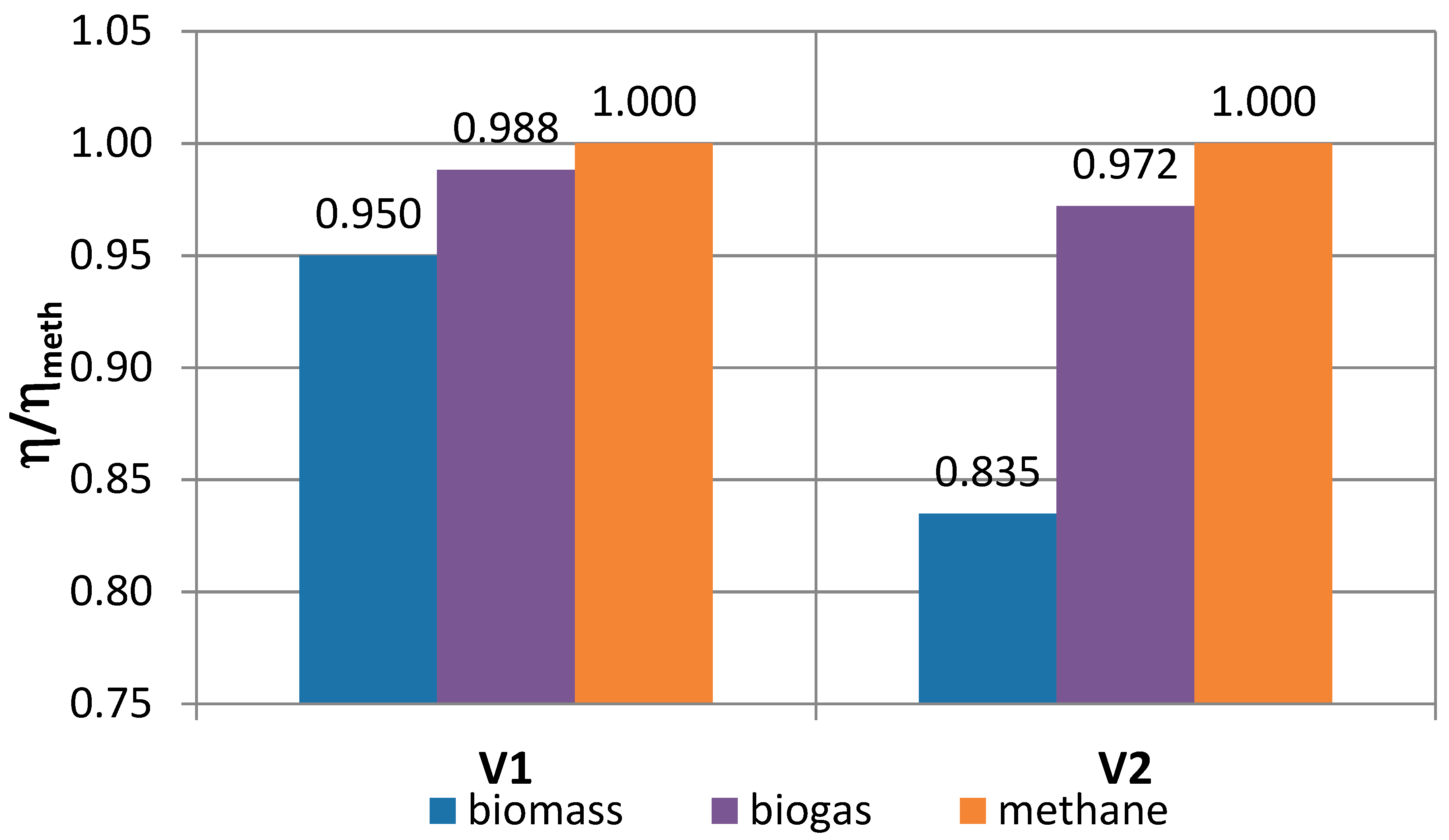
| η/ηmeth | V1 | 0.950 | 0.988 | 1.000 |
| V2 | 0.835 | 0.972 | 1.000 | |
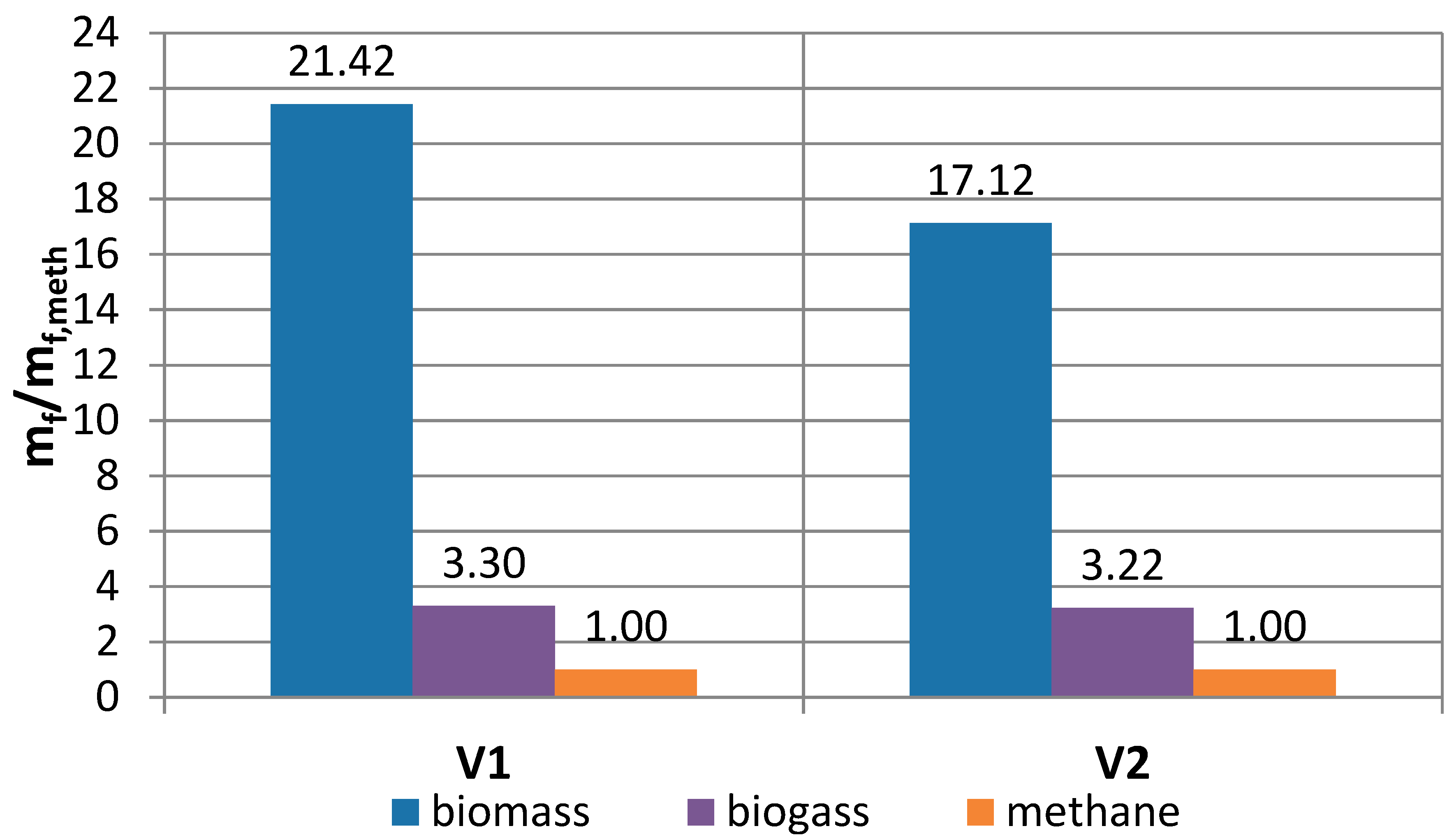
| mf/mf,meth | V1 | 21.42 | 3.30 | 1.00 |
| V2 | 17.12 | 3.22 | 1.00 | |
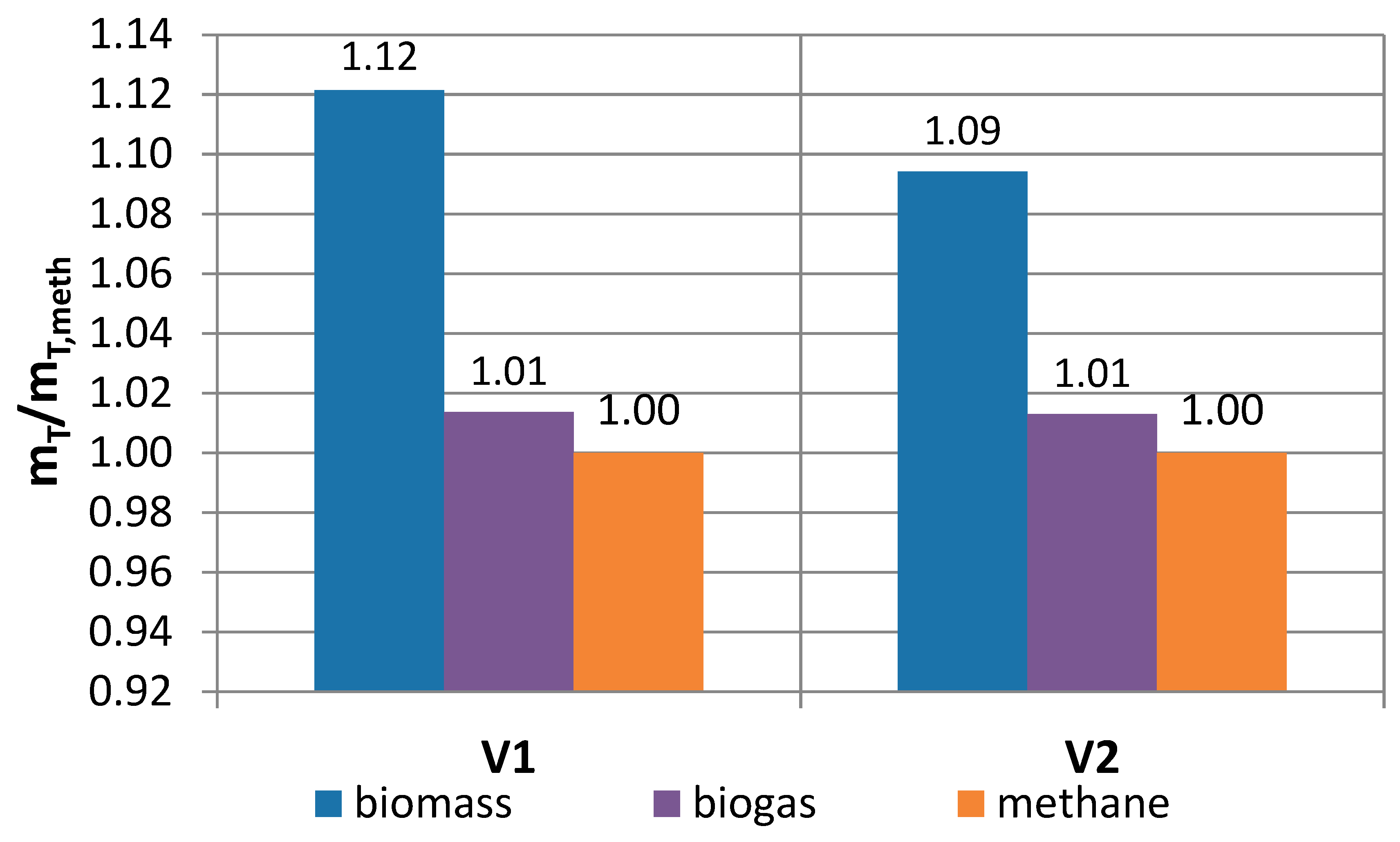
| mT/mT,meth | V1 | 1.12 | 1.01 | 1.00 |
| V2 | 1.09 | 1.01 | 1.00 | |
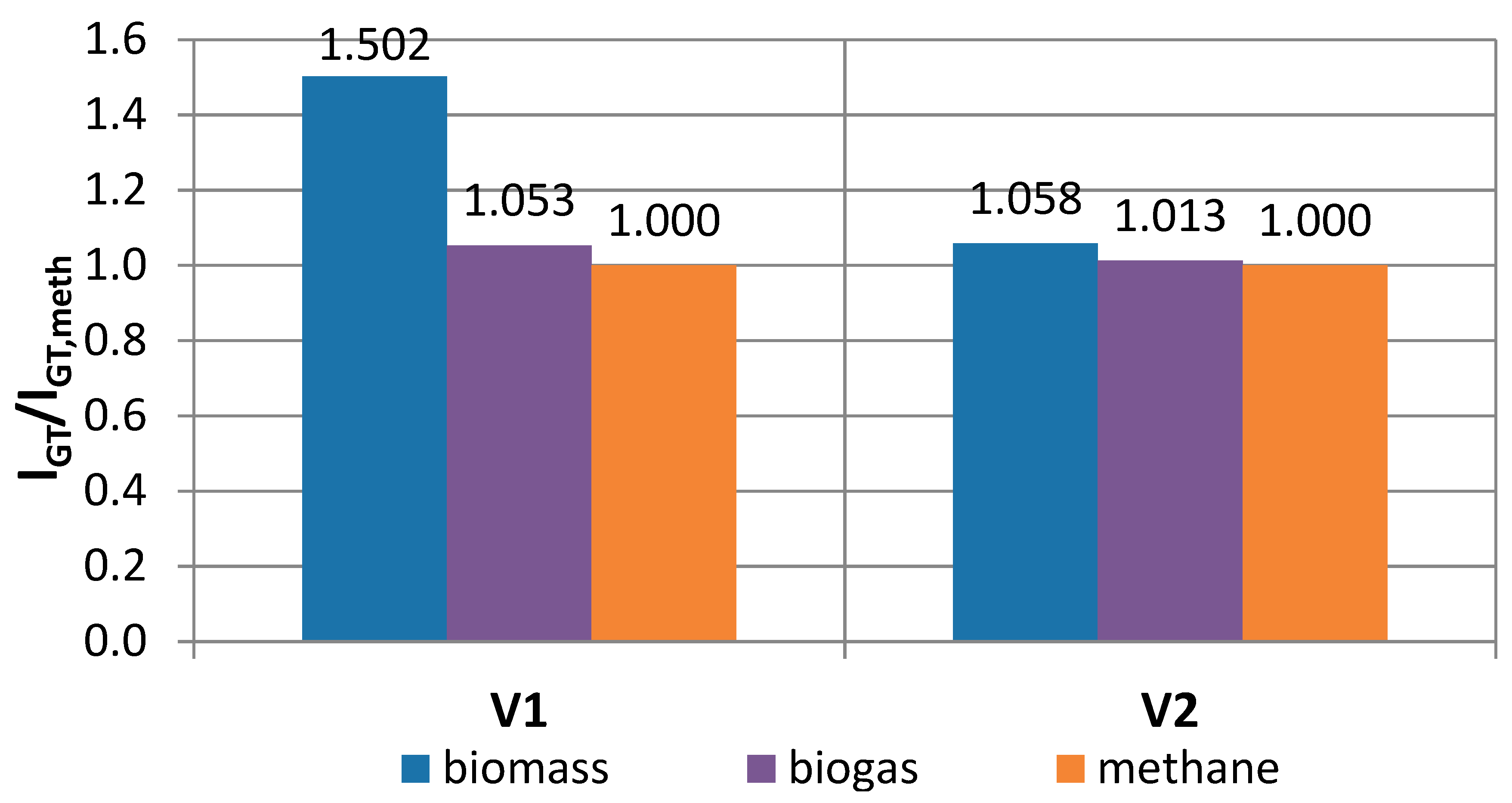
| lGT/lGT,meth | V1 | 1.502 | 1.053 | 1.000 |
| V2 | 1.058 | 1.013 | 1.000 | |
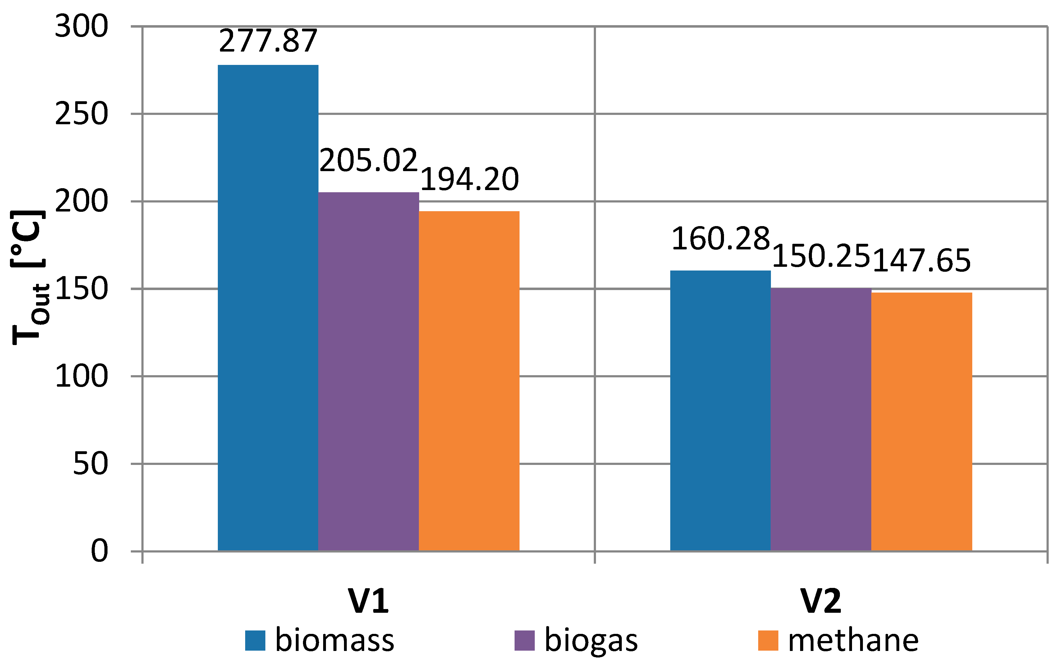
| Tout | V1 | 277.87 | 205.02 | 194.20 |
| V2 | 160.28 | 150.25 | 147.65 |
| Fuel | ηV2/ηV1 | m*/mc |
|---|---|---|
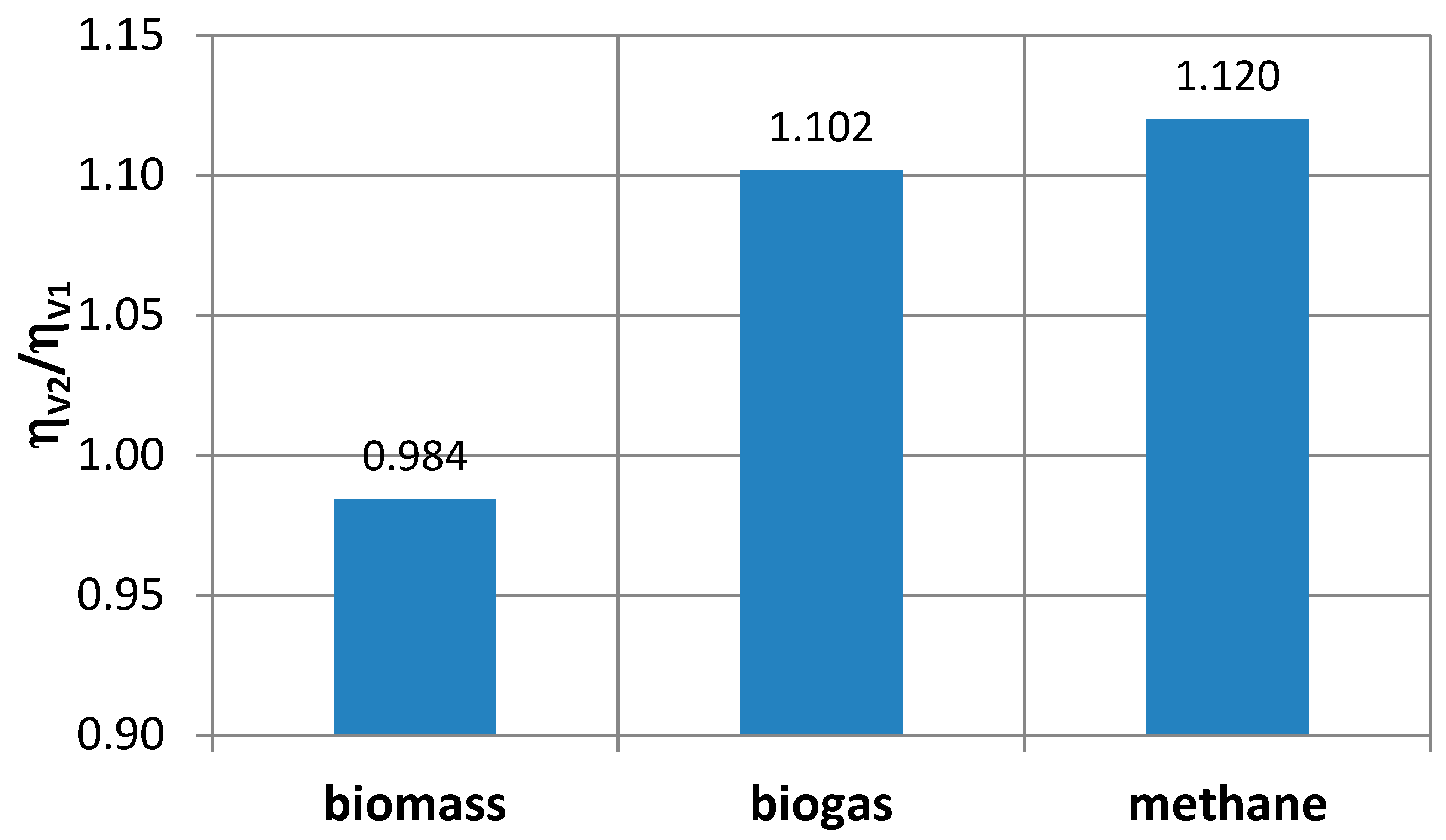
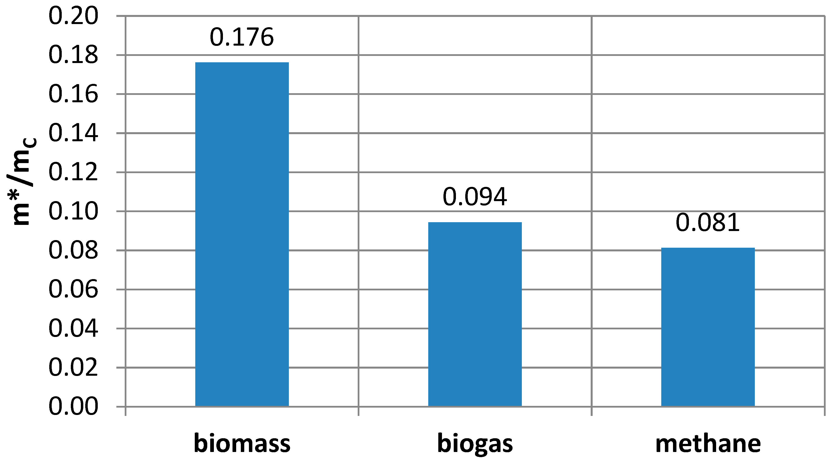
| Biomass | 0.984 | 0.176 |
| Biogas | 1.102 | 0.094 |
| Methane | 1.120 | 0.081 |
© 2019 by the authors. Licensee MDPI, Basel, Switzerland. This article is an open access article distributed under the terms and conditions of the Creative Commons Attribution (CC BY) license (http://creativecommons.org/licenses/by/4.0/).
Share and Cite
Mikielewicz, D.; Kosowski, K.; Tucki, K.; Piwowarski, M.; Stępień, R.; Orynycz, O.; Włodarski, W. Gas Turbine Cycle with External Combustion Chamber for Prosumer and Distributed Energy Systems. Energies 2019, 12, 3501. https://doi.org/10.3390/en12183501
Mikielewicz D, Kosowski K, Tucki K, Piwowarski M, Stępień R, Orynycz O, Włodarski W. Gas Turbine Cycle with External Combustion Chamber for Prosumer and Distributed Energy Systems. Energies. 2019; 12(18):3501. https://doi.org/10.3390/en12183501
Chicago/Turabian StyleMikielewicz, Dariusz, Krzysztof Kosowski, Karol Tucki, Marian Piwowarski, Robert Stępień, Olga Orynycz, and Wojciech Włodarski. 2019. "Gas Turbine Cycle with External Combustion Chamber for Prosumer and Distributed Energy Systems" Energies 12, no. 18: 3501. https://doi.org/10.3390/en12183501
APA StyleMikielewicz, D., Kosowski, K., Tucki, K., Piwowarski, M., Stępień, R., Orynycz, O., & Włodarski, W. (2019). Gas Turbine Cycle with External Combustion Chamber for Prosumer and Distributed Energy Systems. Energies, 12(18), 3501. https://doi.org/10.3390/en12183501