1. Introduction
With the continuous maturation of photovoltaic and other renewable energy power generation technologies, the installed capacity is getting larger and larger, and the megawatt-scale photovoltaic microgrid is gradually put into operation [
1]. The randomness and volatility of photovoltaic power generation will adversely affect the stable and reliable operation of the microgrid [
2], and the expansion of installed capacity will place higher requirements on the stability of the microgrid. The large-capacity hybrid energy storage system applied to the megawatt photovoltaic microgrid is an effective method to reduce the photovoltaic output fluctuation in the microgrid and improve the stability of the microgrid. Therefore, how to effectively control the large-scale hybrid energy storage system has become a problem to be resolved for a large-scale photovoltaic microgrid system [
3].
Current energy storage media can be divided into power storage media and energy storage media [
4]. The power storage media is represented by supercapacitor and superconducting magnetic energy storage. It has large instantaneous power throughput, fast response, and a long cycle life, but its energy storage capacity is low. The energy storage medium is represented by lead-acid batteries and lithium-ion batteries, and the storage capacity is large, but the instantaneous power throughput capacity is limited, and the cycle life is relatively short [
5]. In order to meet the needs of microgrid for large capacity, high power and low response time of energy storage system, using power storage media and energy storage media to form a hybrid energy storage system (HESS) is a current solution [
6].
As the proportion of photovoltaic power generation in power generation increases, the capacity of energy storage systems required in microgrids continues to increase, and traditional centralized single-group large-capacity energy storage cannot meet the flexibility and economic needs of energy storage systems. Therefore, it is a commonly used effective method to divide a large-capacity energy storage system into multiple small-capacity secondary energy storage systems [
7]. In reference [
8], a hybrid microgrid hybrid energy storage control strategy based on droop control is proposed to realize the power allocation between energy storage units.
In reference [
9], a storage energy control method based on low-pass filtration and fuzzy logic control is proposed and the fuzzy membership function is optimized by particle swarm optimization. The high utilization of supercapacitor is realized, and the service life of the battery is prolonged. In reference [
10], the microgrid energy management is divided into two layers. The equipment layer uses dual-mode control combined with droop control to improve system reliability. The system layer uses the equivalent consumption minimization strategy to allocate the system net power. The literature [
11] proposes a variable threshold energy storage system control strategy. No precise microgrid fluctuation prediction data is needed in the control process, but it depends on historical data. If the environment changes greatly, the system may have large errors.
In reference [
12], based on the distributed power supply, load, and energy storage system status of DC (direct current) microgrid, a multi-variable fuzzy control method for hybrid energy storage system is proposed, and a better DC microgrid bus voltage suppression effect is obtained, but the coordination between distributed hybrid energy storage systems is not considered. In reference [
13], this paper studies the islanded AC (alternating current) microgrid with hybrid energy storage system, and proposes a power sharing virtual impedance control strategy to stabilize the AC bus voltage while preventing overcharge and discharge of the battery, but it does not consider the working state of the supercapacitor and discuss in-depth. In reference [
14,
15], from the voltage point of view, the voltage of the supercapacitor is stabilized within a certain range, and the voltage of the supercapacitor is kept constant at the beginning and end of a scheduling period, thereby avoiding the supercapacitor quitting running due to the SOC being too high or too low. In reference [
16], a layered control strategy based on droop control was proposed to realize the coordinated operation of multiple microgrids. In reference [
17], a hybrid energy storage system applied to a standalone photovoltaic micro-grid was proposed, and the corresponding control system was designed based on an artificial neural network, which extended the life of the hybrid energy storage system to some extent and improved the reliability of photovoltaic micro-grid.
In the related research, the power allocation between distributed hybrid energy storage systems does not combine with the state of the hybrid energy storage system itself, resulting in an increase in the energy storage state inconsistency of different energy storage systems during system operation. At the same time, under extreme conditions, the SOC of the supercapacitor in the hybrid energy storage system is prone to be too high or too low, which prevents the system from responding to the fluctuating power quickly, which is harmful to the stable operation of the microgrid [
18,
19].
In order to solve the above problems, this paper proposes a power distribution strategy based on improved hierarchical control for microgrid hybrid energy storage system. The first-level distribution layer considers the residual capacity of each HESS to carry out equal proportional output power distribution. Thus, the HESS with low residual capacity can be implemented with more charges and fewer charges, and the HESS with high residual capacity can be implemented with more charges and fewer charges, thereby ensuring the schedulability of the hybrid energy storage system. The secondary distribution layer considers the working state of the lithium-ion battery, dynamically adjusts the filter constant of the first-order low-pass filter to complete the power distribution of the lithium-ion battery and the supercapacitor in the hybrid energy storage system. Considering the ability of the hybrid energy storage system responding to the fluctuating power under extreme conditions, this paper introduces the transfer current, when the super -capacitor completes the instantaneous power leveling, the lithium-ion battery is used to make the supercapacitor SOC stay at 40%–60%, ensuring that the supercapacitor can quickly respond to the power demand and improve the stability of the photovoltaic micro-grid.
2. Structure Analysis of Photovoltaic Microgrid System
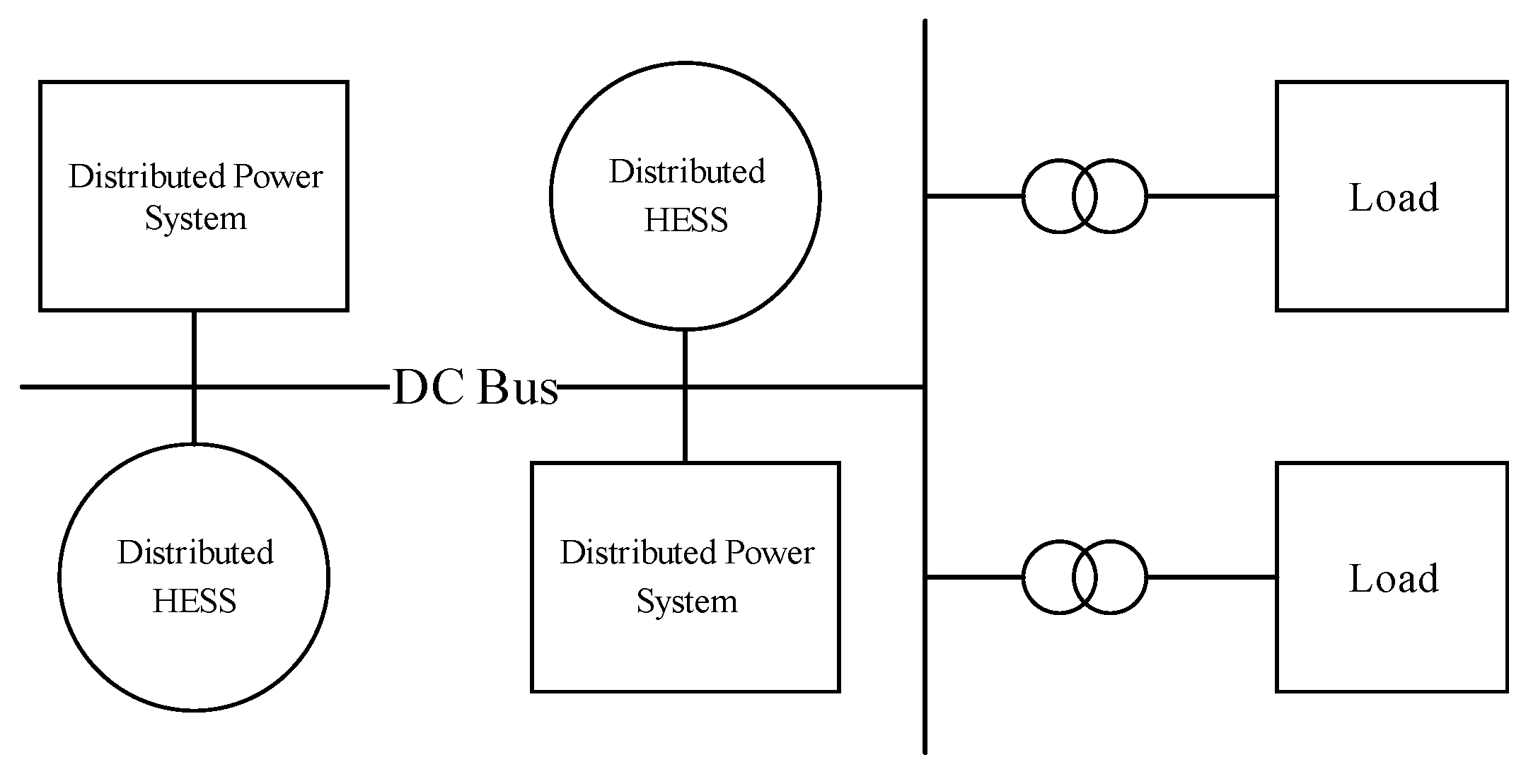
According to the type of bus used in the microgrid, the megawatt-scale microgrid can be divided into: AC bus microgrid and DC bus microgrid. As shown in
Figure 1 below, it is a schematic diagram of the megawatt DC bus microgrid. In general, the megawatt microgrid is mainly divided into three parts: (1) distributed power system; (2) distributed energy storage system; (3) users in the microgrid [
20]. Among them, the distributed power source is a distributed power source such as a photovoltaic array and a wind power generator. The photovoltaic array is connected to the DC bus through DC/DC, and the wind power generator is connected to the DC bus through AC/DC. In this paper, the distributed power supply is mainly a photovoltaic array; the distributed hybrid energy storage system is formed by a certain ratio of lithium-ion battery and supercapacitor, and the way of connecting the lithium-ion battery and the supercapacitor to the DC bus is different according to the demand and the environment. Differently, in this study, lithium-ion batteries and supercapacitors are respectively connected to the DC bus through DC/DC; the DC/AC converter is usually used in the micro-grid to convert the DC power delivered by the DC bus into AC power for daily use.
Compared with small-scale photovoltaic microgrids, megawatt-scale photovoltaic microgrid systems are more complex, including not only a large number of distributed photovoltaic power generation systems, but also a large number of distributed hybrid energy storage systems, and users in the micro-grid, the quantity and types are not comparable to the traditional small microgrid. Therefore, the power stabilization method corresponding to the power storage system and the energy storage system in the small microgrid is obviously not directly usable here, so a new control method must be proposed.
3. Hierarchical Control Strategy for Distributed Hybrid Energy Storage Systems
Although the structure of the distributed hybrid energy storage system applied to the megawatt-scale microgrid is more complicated, the basic idea of the energy management problem is consistent with the traditional method. As shown in
Figure 2, the control strategy structure of the distributed hybrid energy storage system proposed in this paper is presented. The distributed hybrid energy storage system control is divided into two layers, namely, a primary distribution layer and a secondary distribution layer. The first-level distribution layer uses the total unbalanced power between the distributed power source and the user as the output power of the distributed hybrid energy storage system and distributes it to each hybrid energy storage system in the micro-grid, in which different hybrid energy storage systems are considered. The remaining capacity allocates the required power according to the remaining capacity ratio. The second distribution layer passes the distribution power of the first distribution layer into the first-order low-pass filter to obtain the high-frequency power component and low-frequency power component. Considering the SOC of lithium-ion battery, the filtering time constant is dynamically modified to adjust the distribution result of first-order low-pass filtering. Therefore, the advantages of high energy density of lithium ion batteries and high-power density of ultracapacitors can be brought into play.
Considering that the hybrid energy storage system needs to keep great response ability in an extreme situation. Therefore, the transfer current is introduced after the supercapacitor completes the stabilization goal, so that the SOC of the supercapacitor is maintained at 40%–60%, ensuring that the supercapacitor can quickly respond to the power demand and improve the stability of the photovoltaic microgrid system.
3.1. Distributed Hybrid Energy Storage System First Distribution Layer Control Strategy
The distributed hybrid energy storage system consists of a number of different hybrid energy storage systems. These hybrid energy storage systems differ in terms of energy storage capacity and capacity ratio, and the service life of these hybrid energy storage systems is also different. Therefore, there is a difference in the maximum output power of different hybrid energy storage systems. If the fluctuation power is evenly distributed without considering the difference between the hybrid energy storage systems during use, the energy storage state inconsistency of different hybrid energy storage systems may be enhanced, thus affecting the overall performance of the distributed hybrid energy storage system. Therefore, when specifying the power allocation between hybrid energy storage systems, this paper fully considers the current residual capacity state of a hybrid energy storage system, as shown in Equation (1) is the formula for calculating the remaining capacity of the hybrid energy storage system.
where
is the difference between load power and photovoltaic output power. When
, the hybrid energy storage system discharges, and when
, the hybrid energy storage system charges.
and
is the current SOC and maximum energy storage capacity of number i hybrid energy storage system.
and
are the upper and lower limits of the SOC of the hybrid energy storage system of number
i energy storage system respectively, and the SOC calculation formula of the
i-th hybrid energy storage are as shown in Formula (2).
where
is the current charge capacity of
i-th lithium-ion battery;
is the current charge capacity of
i-th supercapacitor;
is the maximum charge capacity of
i-th lithium-ion battery;
is the maximum charge capacity of
i-th supercapacitor;
is the proportion of lithium-ion battery charge capacity to
i-th HESS.
The power allocation between hybrid energy storage systems needs to consider the continuous schedulability of the energy storage system, that is, the residual capacity deviation between the hybrid energy storage systems should be kept within a certain range, thus ensuring that the distributed energy storage system can normally output in the next scheduling period. In order to prevent the problem of over-discharge, as well as over-charging of the system with low residual capacity during the output of the hybrid energy storage system, this paper introduces the residual capacity ratio output control strategy between the hybrid energy storage systems.
First, determine the type of output of the hybrid energy storage system, that is, the charge output or the discharge output; then calculate the remaining available capacity under the output type, and perform the equal proportion of the output power distribution according to the ratio of the remaining available capacity. It can be seen from the above analysis that the remaining capacity of the hybrid energy storage system can be obtained by Formula (1), where the total output power of the distributed power source in the micro grid is defined as , the total load power of the power side is , and the expression of the output target value of the hybrid energy storage is Equation (3).
When the hybrid energy storage system is operating in the discharge mode,
is positive, and vice versa
is negative. After the first-level distribution layer,
is allocated to each hybrid energy storage system in the photovoltaic micro-grid, and the processing target power of the hybrid energy storage system is
, and its expression is as shown in Formula (4).
where
is the ratio of the remaining capacity occupied by a hybrid energy storage system in the photovoltaic micro-grid.
is the current remaining capacity of the hybrid energy storage system.
3.2. Control Strategy of Secondary Distribution Layer of Hybrid Energy Storage System
The secondary distribution layer mainly completes the power distribution between the lithium-ion battery and the supercapacitor internal energy storage medium inside the hybrid energy storage system. In this paper, the first-order variable-filtering time low-pass filtering algorithm is used to complete the initial distribution of the output power. That is, the low-frequency power obtained by the first-order low-pass filtering is assumed by the lithium-ion battery, and high-frequency power is obtained by the supercapacitor. Since the frequency tolerance of the lithium-ion battery to the output power varies during the operation of the system, the low-pass filter time constant is dynamically adjusted based on the current SOC of the lithium-ion battery.
Considering that hybrid energy storage system is under extremely bad working conditions. For example, when the hybrid energy storage system is charged or discharged for a long time, the energy density of the supercapacitor is very low, and the SOC of the supercapacitor is likely to be too high or too low. Hybrid energy storage system is not working properly. Therefore, in this paper, after the ultracapacitor completes the assigned power target, the SOC of the ultracapacitor is adjusted by using lithium ion battery to be between 40% and 60%. Improving the continuous schedulability of hybrid energy storage system is helpful to the stable operation of photovoltaic micro-grid.
Considering that the hybrid energy storage system is under extreme conditions, such as long-term, continuous charging or discharging of hybrid energy storage system, due to the small energy density of the supercapacitor, it is easy for the supercapacitor SOC to be too high or too low, affecting the normal function of the energy storage system. Therefore, after the supercapacitor completes the allocated power target, the lithium-ion battery is used to adjust the SOC of the supercapacitor to make it stay at 40%–60%, and the continuous schedulability of the hybrid energy storage system is improved, which contribute to the stable operation of the photovoltaic microgrid.
3.2.1. First-Order Variable Filter Constant Low-Pass Filter Allocation
The output characteristics of the first-order discrete low-pass filter are shown in Equation (5).
where
is the output at time
t,
is the period adopted by the system,
is the filtering time constant,
is the input at time
t, and
is the output at time
t − 1. The calculation formula obtainable according to the discrete form of the first-order low-pass filtering is as shown in Equation (6).
where
is the target power of a hybrid energy storage system at time
t.
is the target power of lithium-ion battery at time
t.
is the supercapacitor output target power.
is the period adopted by the system,
is the filtering time constant. We can rewrite formula (6) as Formula (7) just for convenience.
where
is the filter coefficient and
. It can be known from Equation (7) that the lithium-ion battery provides the low frequency component of the hybrid energy storage system, and the power output target of the supercapacitor is obtained according to the law of conservation of energy as follows:
In the first-order low-pass filtering algorithm, the selection of the filter coefficient plays a decisive role in the effect of the whole algorithm. If the filter coefficient is fixed, the different operating states of the lithium-ion battery and the supercapacitor cannot be considered, so a low-pass filtering coefficient is required to be adaptively adjusted to suit the different operating states of the lithium-ion battery and the supercapacitor in order to ensure the continuous schedulability of the system. Thus, the output powers in Equations (7) and (8) need to meet the constraints in Equation (9):
where
is the current SOC of the lithium-ion battery, and
and
are the upper and lower limits of the SOC of the lithium-ion battery,
is the current SOC of the supercapacitor, and
and
are the upper and lower limits of the SOC of the supercapacitor. The range of the filter coefficient
can be obtained by the above limitation and the relationship between the SOC and the output power. At the same time, the adaptive modification formula of the filter system is established by combining the respective SOC characteristics of the supercapacitor:
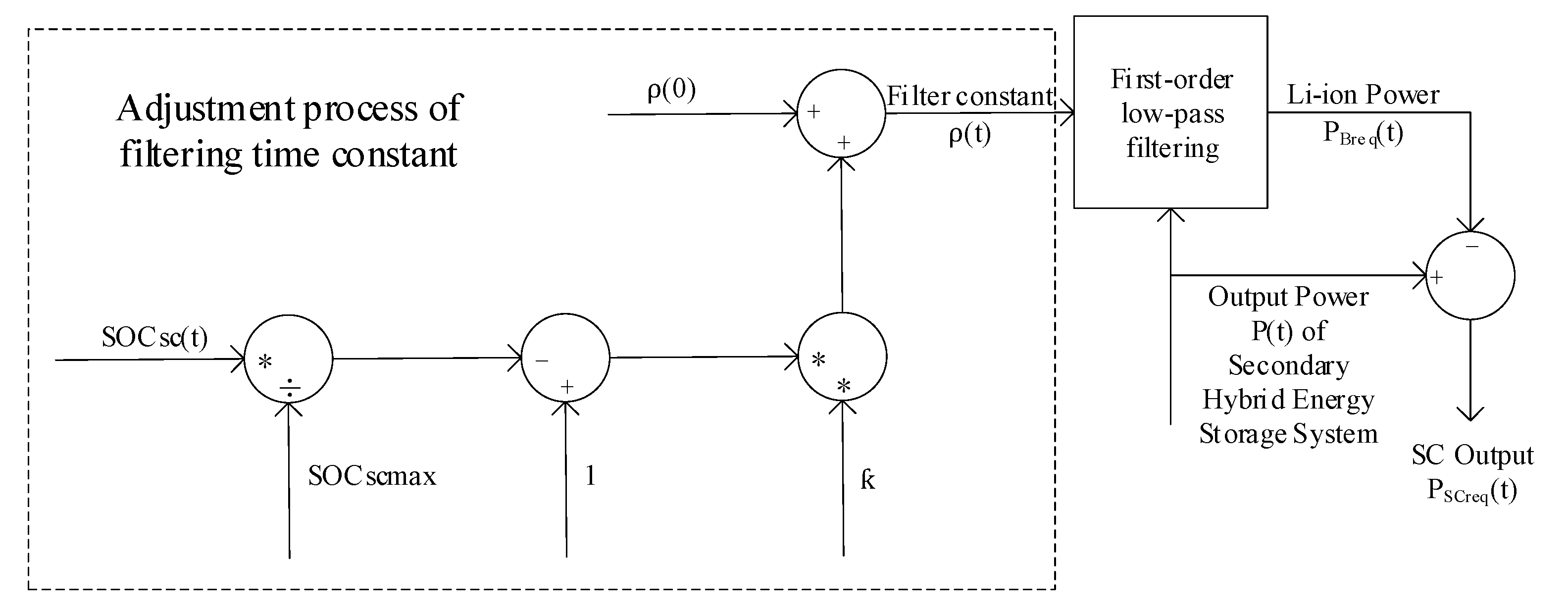
In the formula, is the correction filter coefficient at time t, is the initial correction filter coefficient and the value in this paper is 5. is the adjustment scale coefficient and the value in this paper is 0.8, is the adjustment amount of the correction filter time constant. The calculation formula is as shown in Formula (11).
The SOC of the supercapacitor at t time is
, the upper limit of the supercapacitor SOC is
. The working principle of the first-order variable filter constant low-pass filtering algorithm is shown in
Figure 3.
3.2.2. Transfer Current Optimization Supercapacitor SOC
Due to the small energy density of the supercapacitor, the SOC changes relatively quickly during operation. When the hybrid energy storage system works under some extreme conditions, such as continuously discharging or charging the microgrid, the SOC of the supercapacitor may approach the upper and lower limits of the SOC, thus making the supercapacitor not continue to respond well to the fluctuation power demand of the microgrid, which may even cause the supercapacitor to malfunction. In order to avoid such problems and improve the continuous schedulability of supercapacitors, this paper considers the SOC margin of the supercapacitor and introduces the transfer current so that the supercapacitor can achieve the target power of the first-order variable filter constant low-pass filter distribution and can reserve sufficient SOC margin, so that the hybrid energy storage system can work normally under extreme conditions.
Since the supercapacitor has a short duration of charge and discharge during normal operation, it can be approximated that the voltage of the supercapacitor is constant, so that the supercapacitor current can be used to characterize the power change of the supercapacitor. Li-ion batteries can also be used to characterize the change in power. The relationship between the target output power
and
of lithium-ion battery and the supercapacitor and their target current
and
is as shown in Equation (12):
where
is the target output power of
i-th lithium-ion battery.
is the voltage of
i-th lithium-ion battery.
is the target current of
i-th lithium-ion battery.
is the target output power of
i-th supercapacitor.
is the voltage of
i-th supercapacitor.
is the target current of
i-th supercapacitor. The SOC of the supercapacitor after the target power is completed can be obtained by Formula (13):
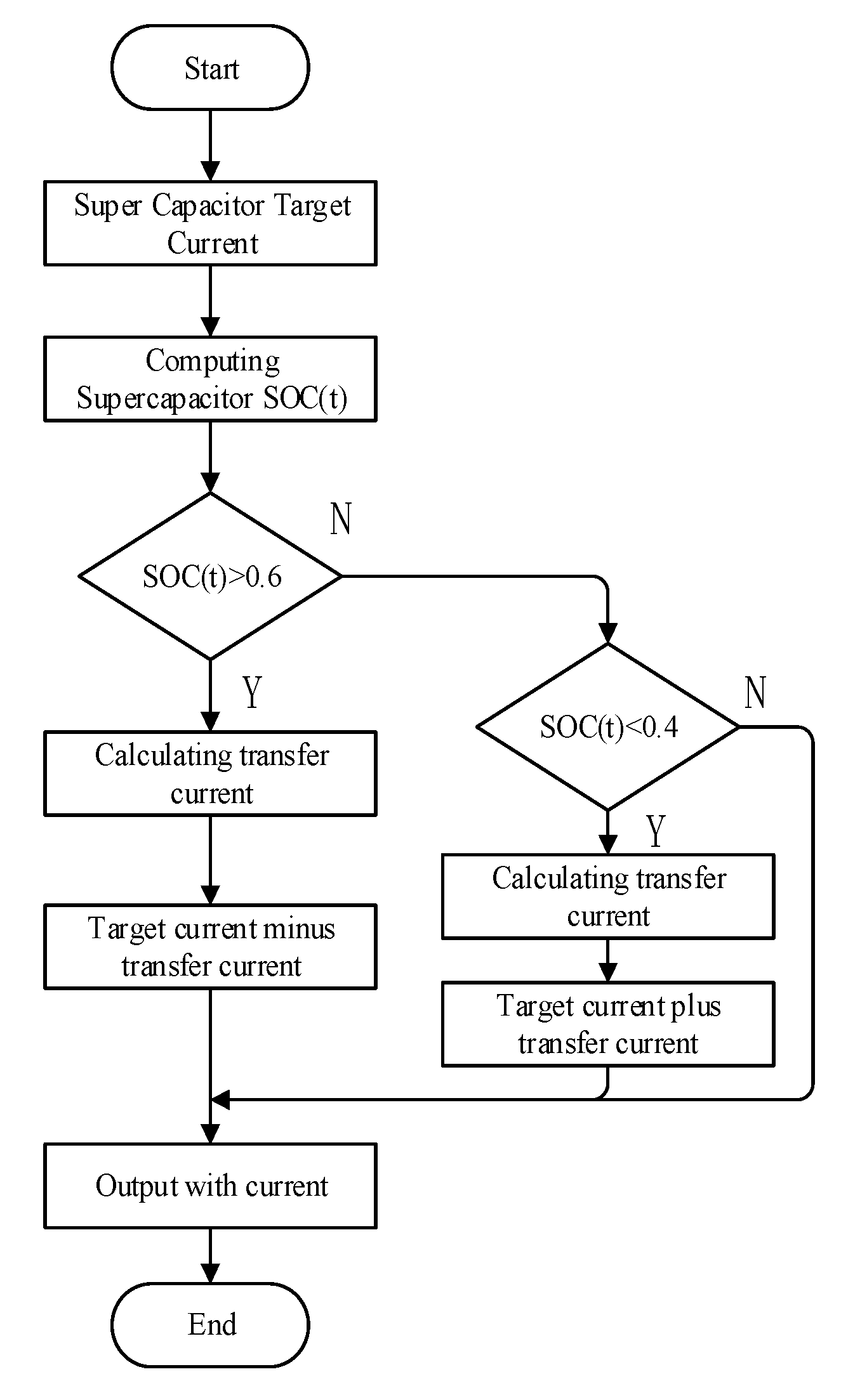
In the formula, is the is supercapacitor charging and discharging efficiency and the value in this paper is 0.95. It can be known from Equations (12) and (13) that when the target power of the supercapacitor, the initial value and SOC are known, the supercapacitor after completing target power value can be calculated. After obtaining , in order to determine whether is at the range of 40%–60%, if the interval is exceeded, the transfer current needs to be introduced to adjust the SOC of the supercapacitor, as shown in Equation (14) is the calculation formula of the transfer current. In the Formula (14), is the discharge transfer current of supercapacitor, and is the charge transfer current of supercapacitor.
After the introduction of the transfer current, during the actual operation of the secondary hybrid energy storage system, the current of the lithium-ion battery is and the current of the supercapacitor is , as shown in Equation (15).
It can be known from Equation (16) that during operation, if the supercapacitor SOC exceeds 60%, the supercapacitor will transfer excess energy to the lithium-ion battery with
. If its SOC is lower than 40%, the lithium-ion battery will transfer energy to the supercapacitor. Due to the low energy density of the supercapacitor, the transfer current itself is small and does not affect the normal operation of the hybrid energy storage system.
Figure 4 is a flow chart of the transfer current correcting the supercapacitor SOC.
4. Case Analysis
In order to verify the effectiveness of the hybrid energy storage hierarchical control strategy proposed in this paper, a simulation model is built in MATLAB (R2019a, MathWorks, Natick, MA, USA) for simulation test. The model data are based on a 300 MW photovoltaic energy storage microgrid system. This photovoltaic microgrid uses three sets of hybrid energy storage systems. The analysis of this example is based on the photovoltaic microgrid on a certain day during the 10:30–11:00 period of operation data. Some parameter information of the photovoltaic microgrid is shown in
Table 1. The main parameters of the simulation model are listed in
Table 2.
It can be seen from the table that the DC bus voltage in the PV microgrid is set as 500 V, and the energy storage capacities of the three different hybrid energy storage systems are 74.5 MWh, 42 MWh and 33.5 MWh respectively. The energy storage capacity of the hybrid energy storage system includes the capacity of the lithium-ion battery and the supercapacitor capacity, in the different hybrid energy storage systems, the capacity ratio of the lithium-ion battery and the supercapacitor is slightly different, respectively: 6:1, 6.5:1, 6.2:1.
In the PV microgrid operation data selected in this paper, the initial SOC of lithium-ion batteries is 32%, 54% and 78%, respectively, in the three different hybrid energy storage systems, and the initial SOC of supercapacitors is 60%, 40% and 70%. The sampling interval is 10 s. Since the system takes less than 1 s from data acquisition to control instruction to actual execution of the instruction, the 10 s sampling interval can well track the output power fluctuation of the photovoltaic microgrid.
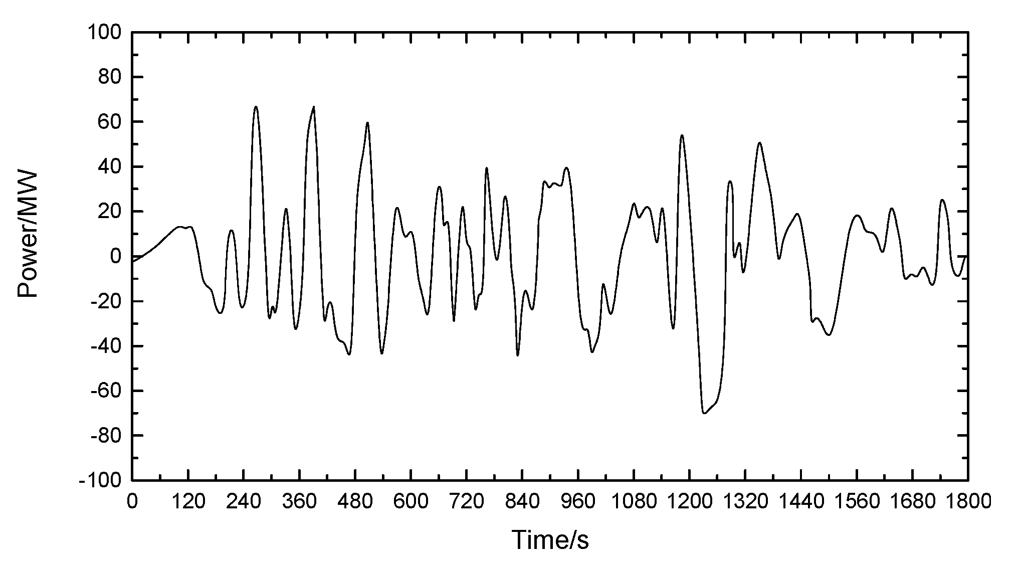
4.1. Distribution Results among Distributed Hybrid Energy Storage Systems
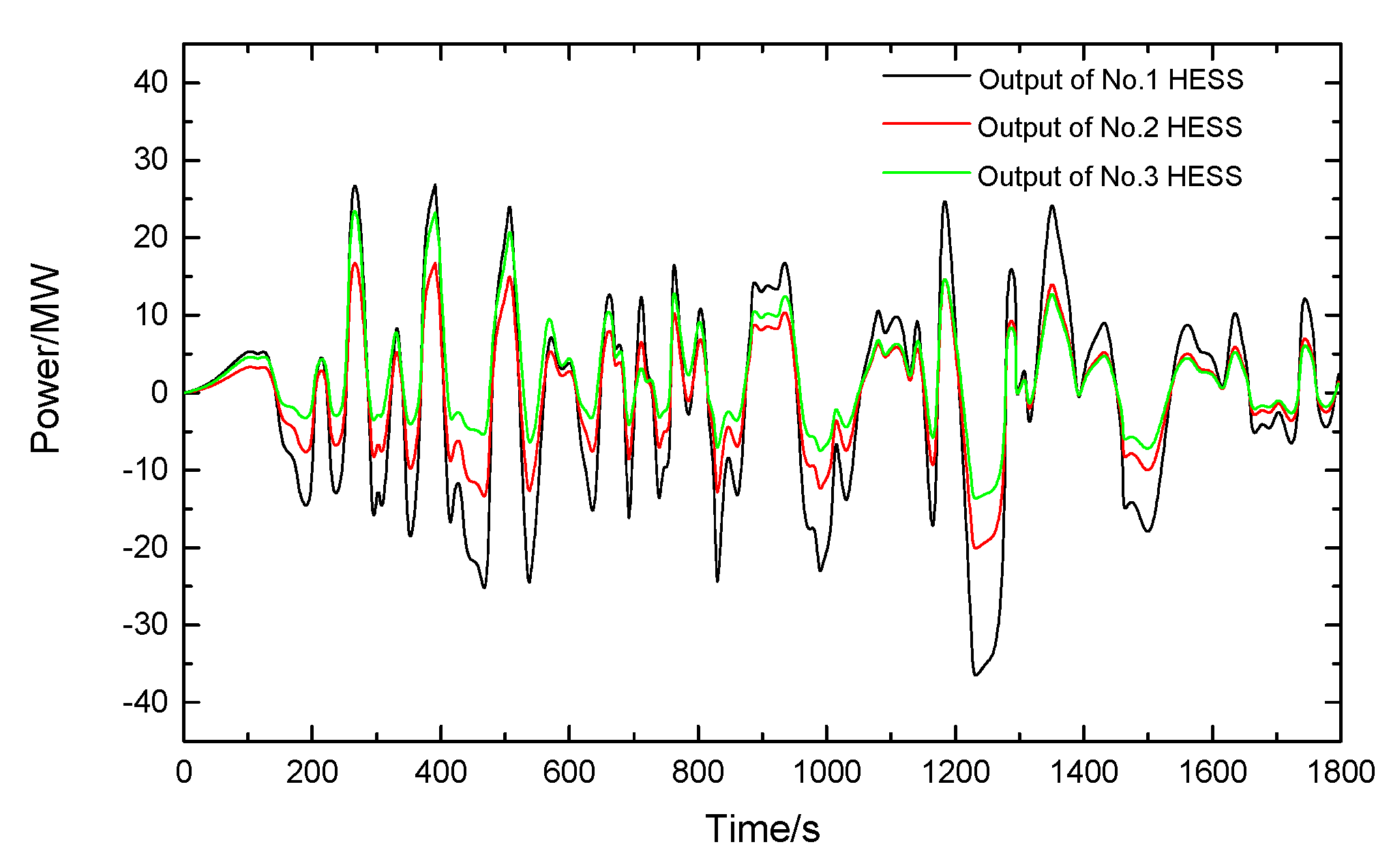
Figure 5 shows the difference between the PV output power and the load demand during the 10:30–11:00 period of the PV microgrid. The unbalanced power is used as the stabilizing target of the distributed hybrid energy storage system. The results of the distribution between the hybrid energy storage systems are shown in
Figure 6.
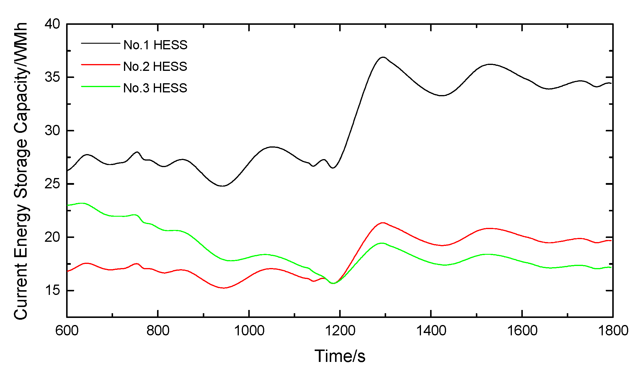
It can be seen from
Figure 6 and
Figure 7 that the distributed hybrid energy storage system adopts the distribution method based on the remaining capacity of the hybrid energy storage system when the power fluctuation of the photovoltaic microgrid is stabilized, which can reasonably and effectively distribute between different hybrid energy storage systems. At around 1200 s, and there is a large power surplus in the microgrid. In this case, distributed hybrid energy storage is needed to absorb this part of the excessive energy. The No. 1 hybrid energy storage system has a large energy storage capacity, so it bears most of the stabilization target, the smaller capacity of the No. 3 bears less target. At this time, the SOC of the No. 3 hybrid energy storage system increased from 44% to 59.7%, an increase of 36%, and according to the traditional average distribution principle, the SOC of the No. 3 hybrid energy storage system is 80%, an increase of 45%. Therefore, the method of this paper reduces the SOC variation of the No. 3 hybrid energy storage system by 9%, which improves the continuous schedulability of the hybrid energy storage system. Under the condition that the photovoltaic power output fluctuation of the microgrid can be stabilized, the residual capacity of the distributed hybrid energy storage system caused by the average distributed power is reduced, resulting in overcharge and discharge of the system.
4.2. Hybrid Energy Storage System Distribution Results
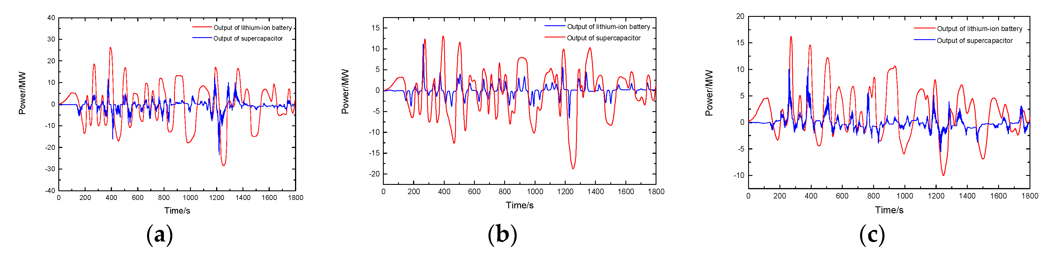
According to the remaining capacity ratio, the output power is further allocated according to the power distribution strategy between the lithium-ion battery and the supercapacitor, and the actual output power target value of the lithium-ion battery and the supercapacitor is obtained. The power of lithium-ion batteries and supercapacitors in different hybrid energy storage systems is shown in
Figure 8.
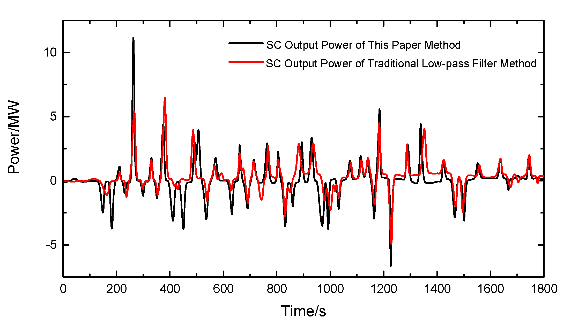
Figure 9 shows the output power curve of the supercapacitor of the No. 2 hybrid energy storage system under the distribution method and the traditional distribution method, respectively.
The variable time constant low-pass filtering method can adjust the filtering time constant of the low-pass filter in real time according to the frequency of the fluctuating power and the energy storage state of the lithium ion battery, and dynamically adjust the power distribution result between the lithium ion battery and the supercapacitor. As shown in
Figure 8, the supercapacitor under this paper method can quickly respond to the power demand of the system during the period of high power fluctuations, for example, at 240 s, the output power of the supercapacitor in this method is 11 MW, while that of the traditional low-pass filtering method is only 5 MW. Similarly, at 1200 s, the output power of the supercapacitor is −7 MW, while the traditional low-pass filter control is −4.97 MW. Therefore, when the fluctuating power is large, the method of this paper can adjust the filter coefficients so that the supercapacitor can provide more power and reduce the output power of lithium ion batteries. Further, when the power fluctuation is small, the supercapacitor can reduce its output power and retain enough SOC margin.
4.3. Transfer Current Rectifies Super-Capcitor SOC
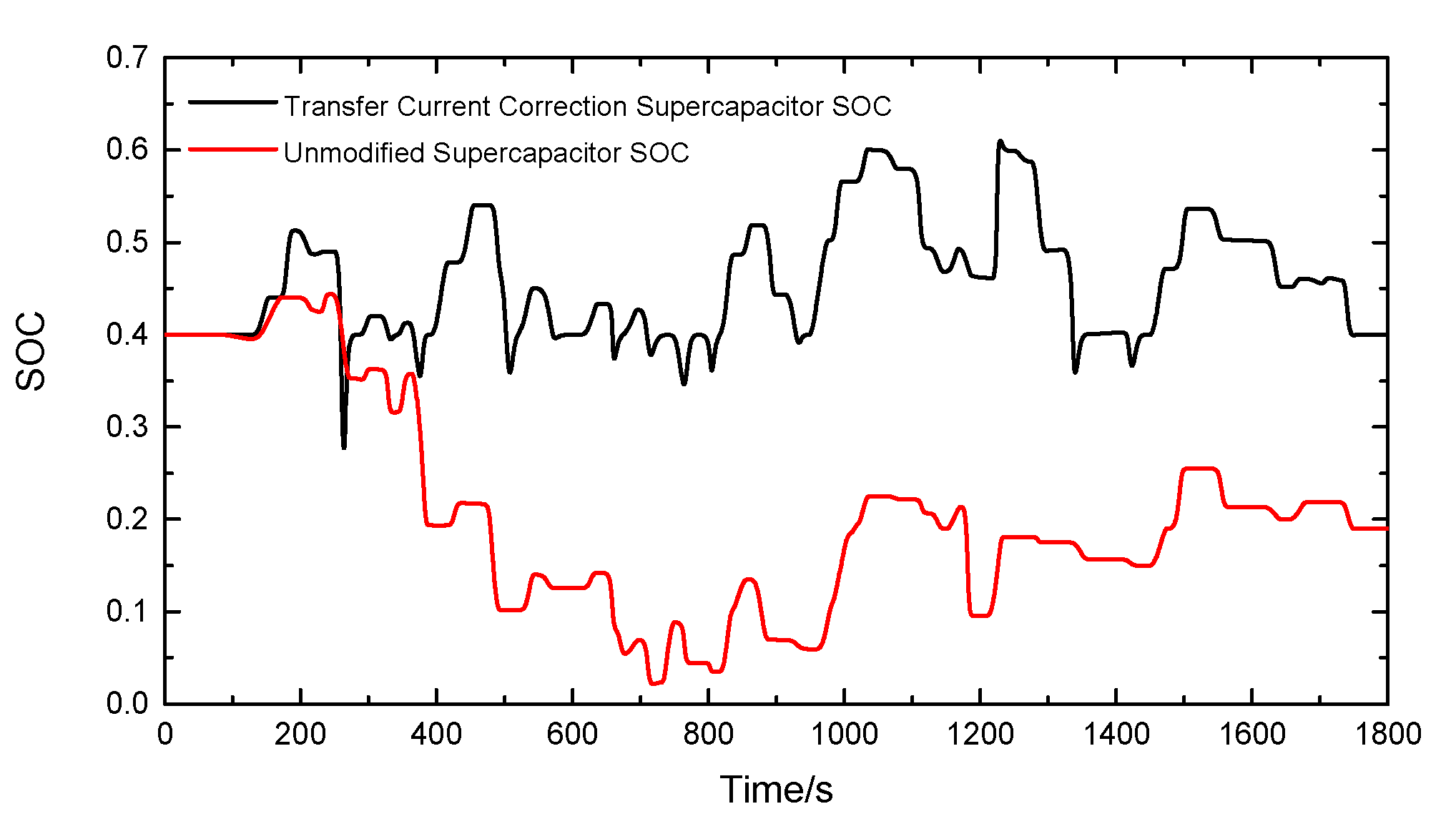
From the previous analysis, the supercapacitor has a large power density and a small energy density. Therefore, although the supercapacitor can provide a large amount of power instantaneously, it cannot last for a long time. In actual use, if a hybrid energy storage system is encountered. When continuous charging or discharging is required, if the SOC of the supercapacitor is not corrected, the supercapacitor is likely to be emptied or full, which may result in the failure to respond to the fluctuating demand of the microgrid fluctuating power in subsequent operations, affecting the normality of the microgrid. run. In this paper, based on the transfer current, when the SOC of the supercapacitor exceeds the set value, the lithium ion battery is used to charge and discharge the supercapacitor, so that the SOC of the supercapacitor is always kept within the set interval, so that the supercapacitor can respond to the demand in time. Power to improve the stability of the microgrid. As shown in
Figure 10 below, the SOC of the supercapacitor under the algorithm and the change of the supercapacitor SOC under the traditional algorithm are shown.
It can be seen from the SOC change diagram of the supercapacitor in
Figure 10 that the SOC of the supercapacitor changes greatly when the transfer current is not introduced, and the energy released by the supercapacitor is greater than the charged energy in the period of 400 s to 800 s, resulting that the SOC gradually droop, and the lowest is below 5%, which is not conducive to the safe and stable operation of the hybrid energy storage system. In this paper, the SOC of the supercapacitor is corrected by the transfer current. It can be seen from the figure that the overall variation of the supercapacitor SOC Smaller, maintained in the range of 40% to 60%, it is able to reserve sufficient residual capacity to stabilize the unbalanced power of the photovoltaic output and the load in the microgrid, which is conducive to the stable operation of the photovoltaic microgrid.


