Study on the Electromagnetic Design and Analysis of Axial Flux Permanent Magnet Synchronous Motors for Electric Vehicles


Abstract
:1. Introduction
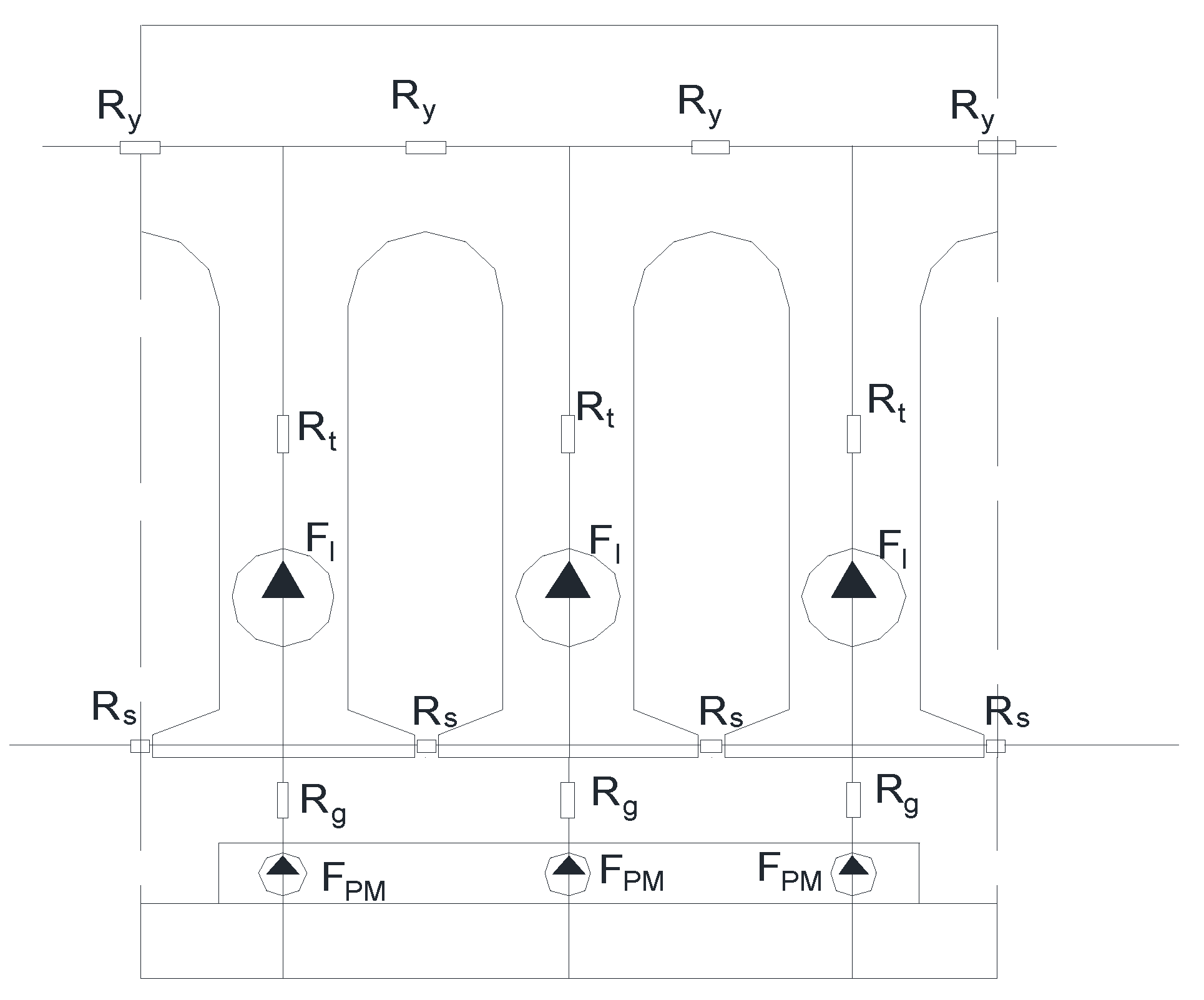
2. Magnetic Path Analysis Algorithm for AFPMSM
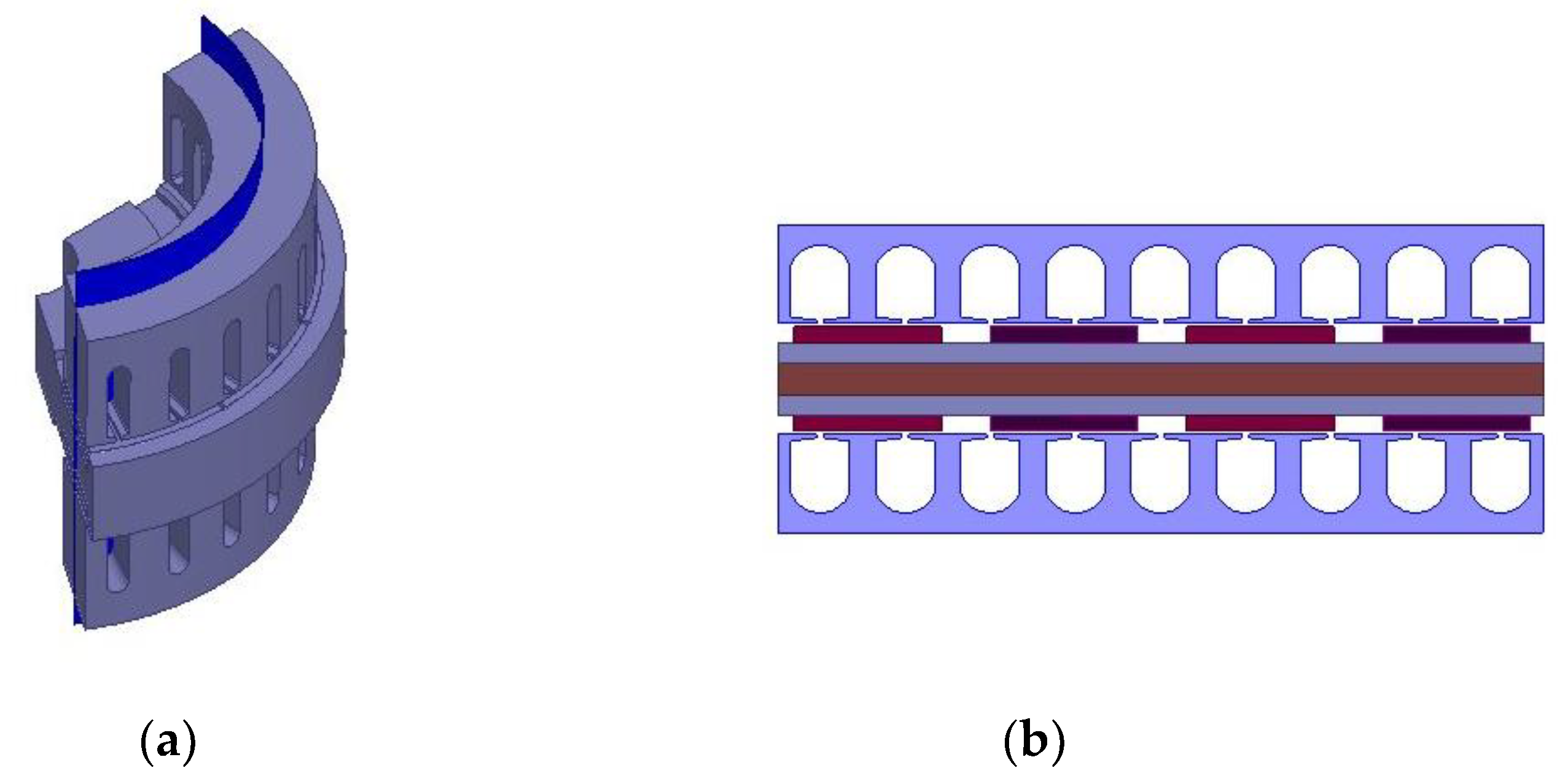
2.1. Modeling and Analysis of Magnetic Circuit Analysis Algorithm
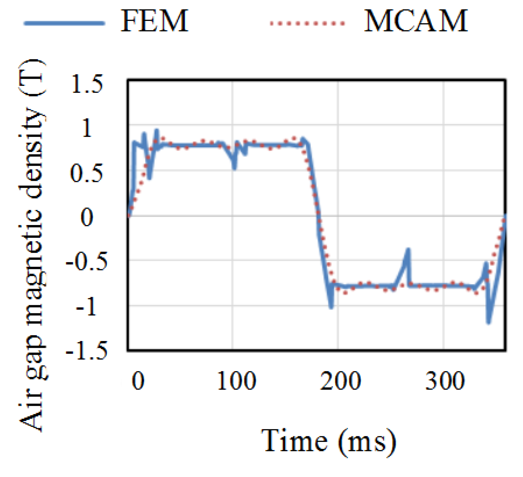
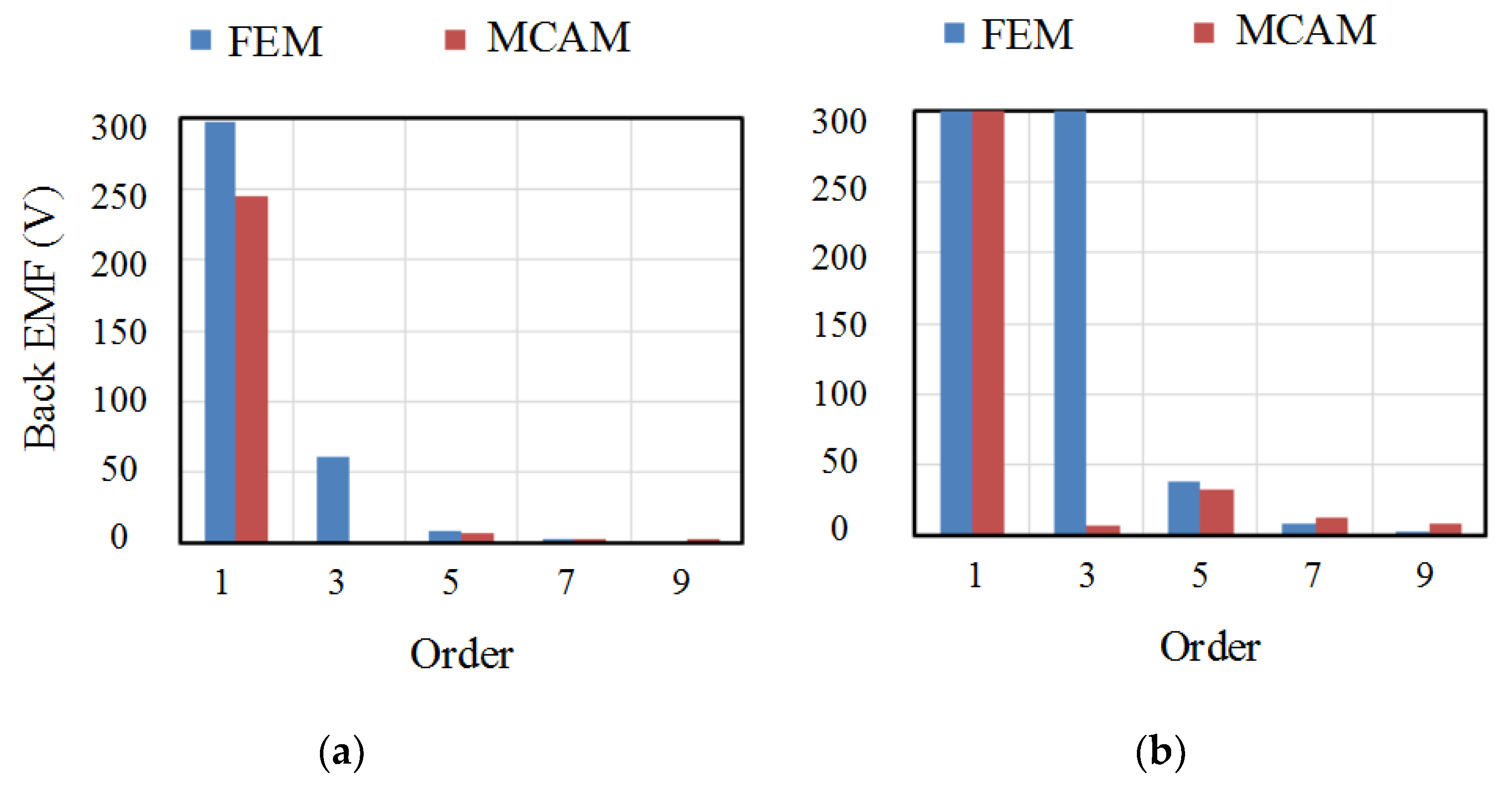
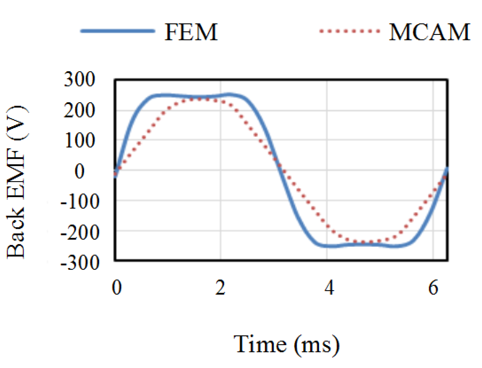
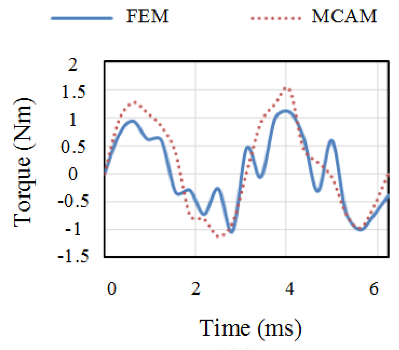
2.2. Comparative Analysis of MCAM and 3D FEM
3. Torque Ripple Optimization of AFPMSM
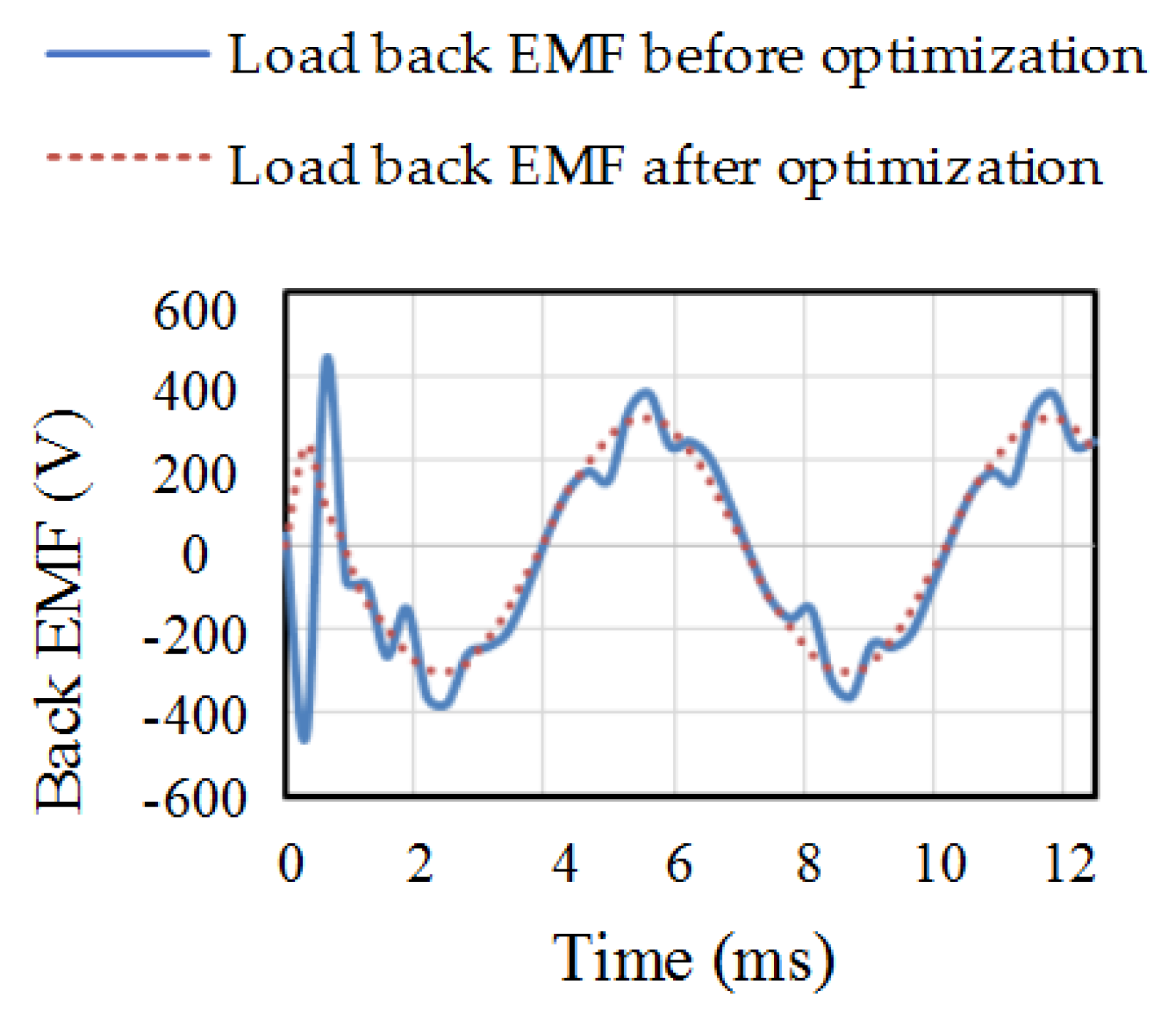
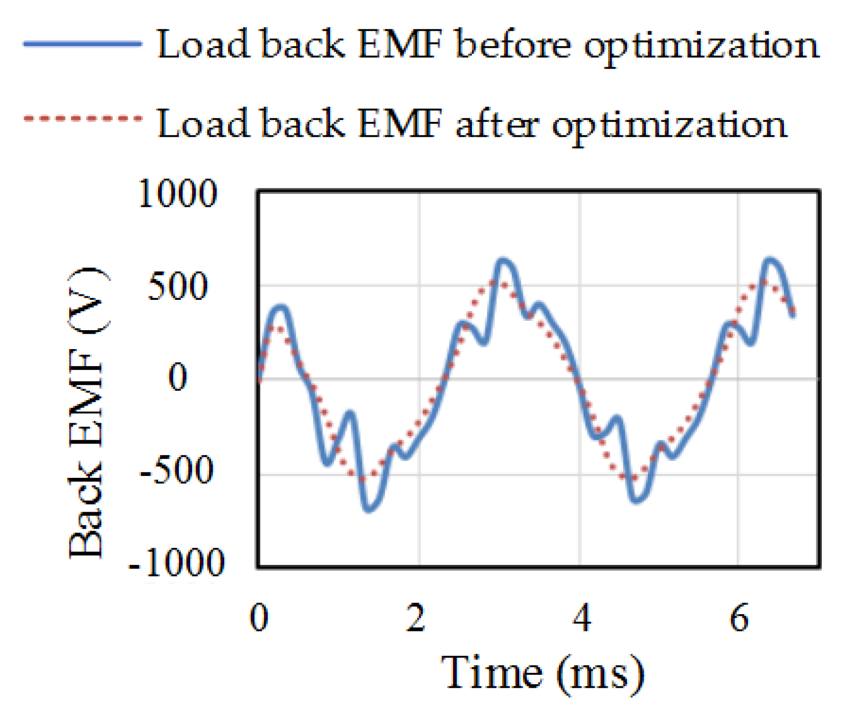
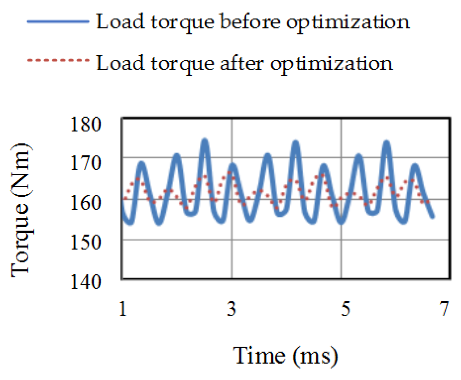
3.1. Comparative Analysis of Rated Load Characteristics at 1600 rpm
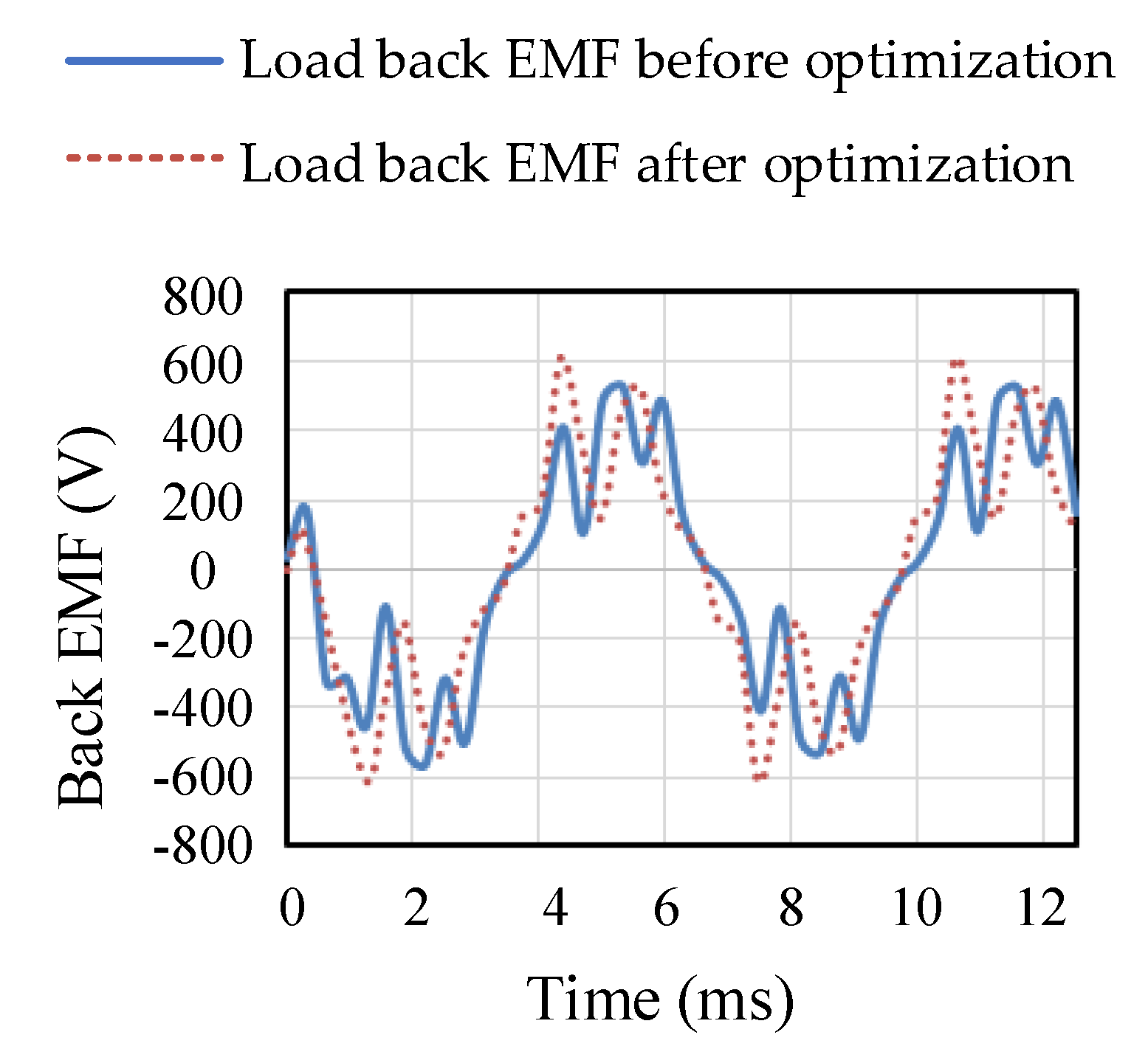
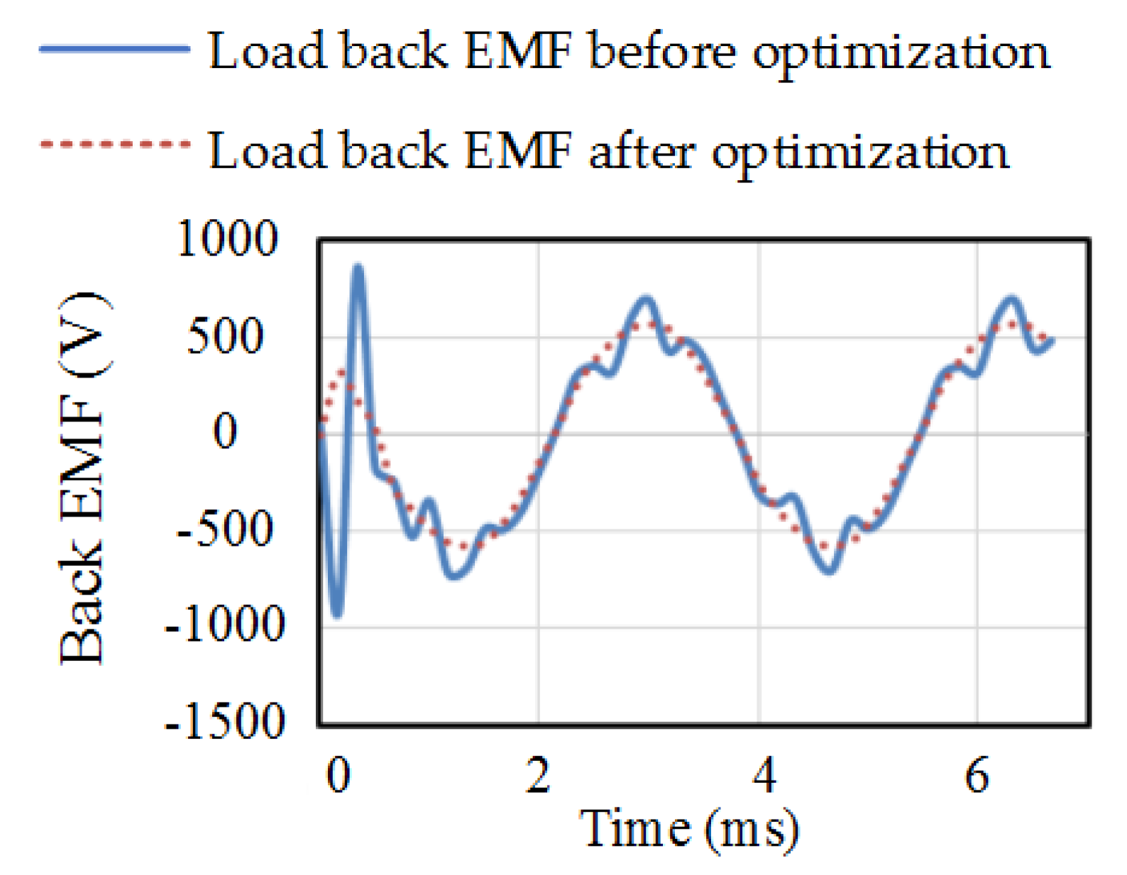
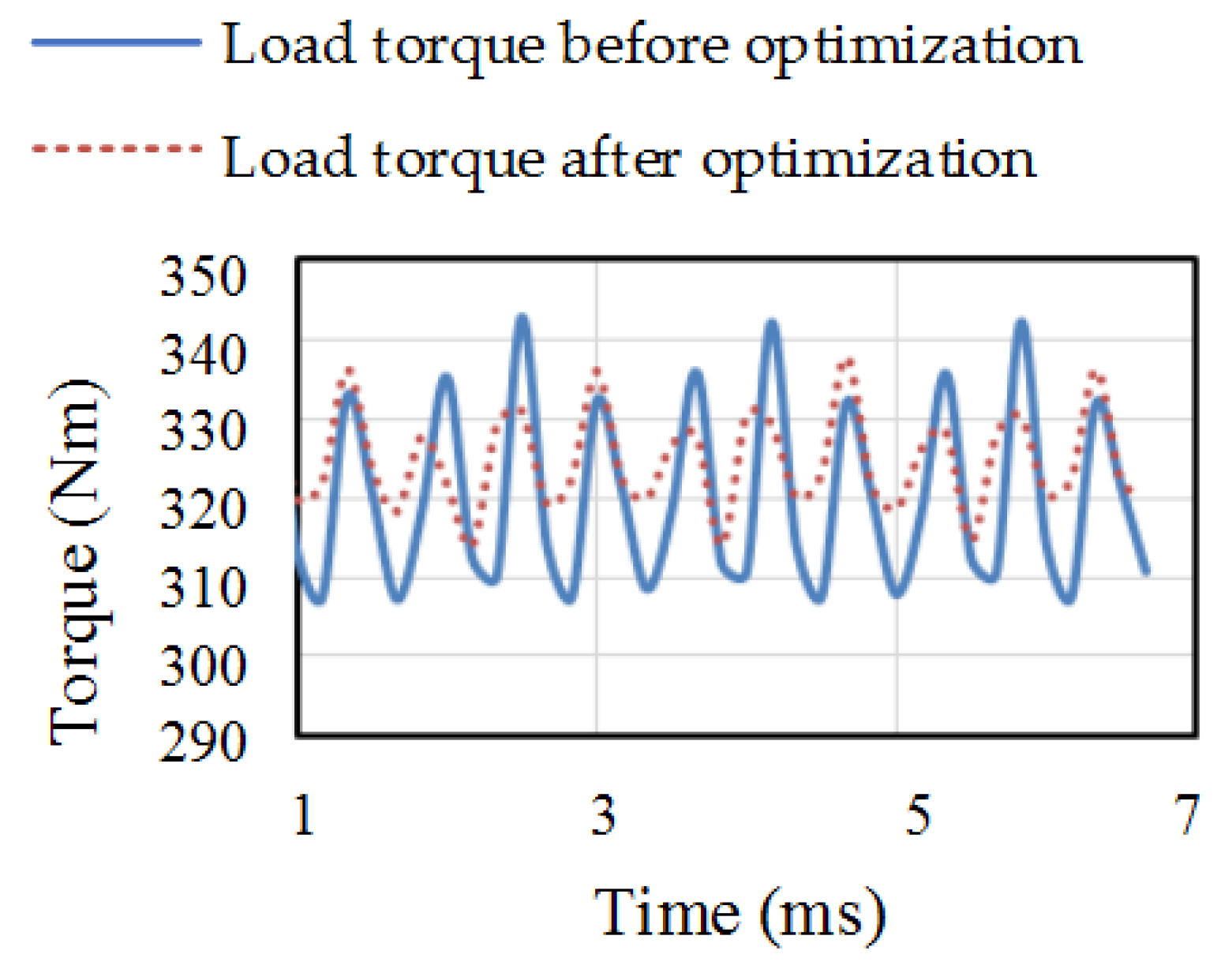
3.2. Comparative Analysis of Peak Load Characteristics at 1600 Rpm
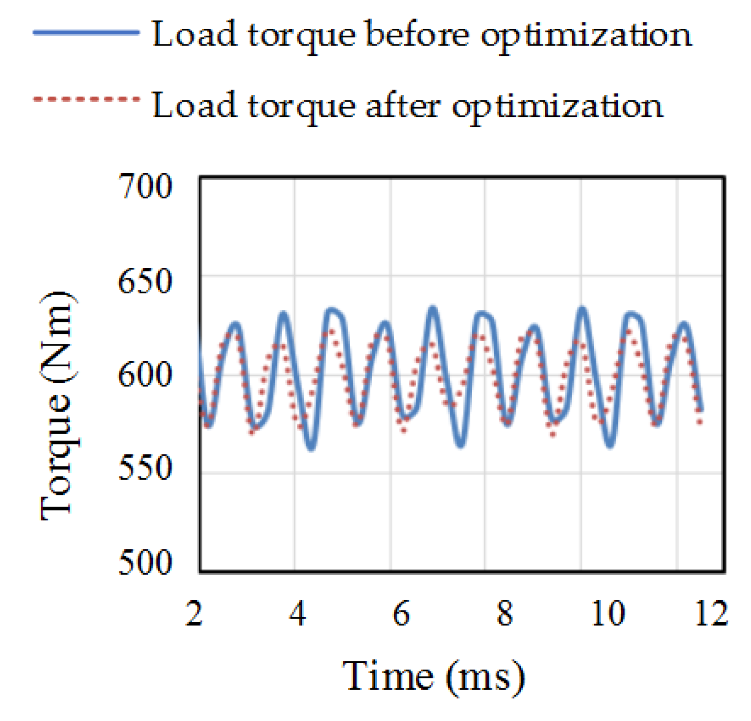
3.3. Comparative Analysis of Rated Load Power Characteristics at 3000 rpm
3.4. Comparative Analysis of Peak Load Power Characteristics at 3000 rpm
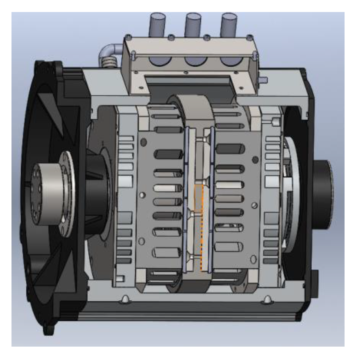
4. Multi-Physics Analysis
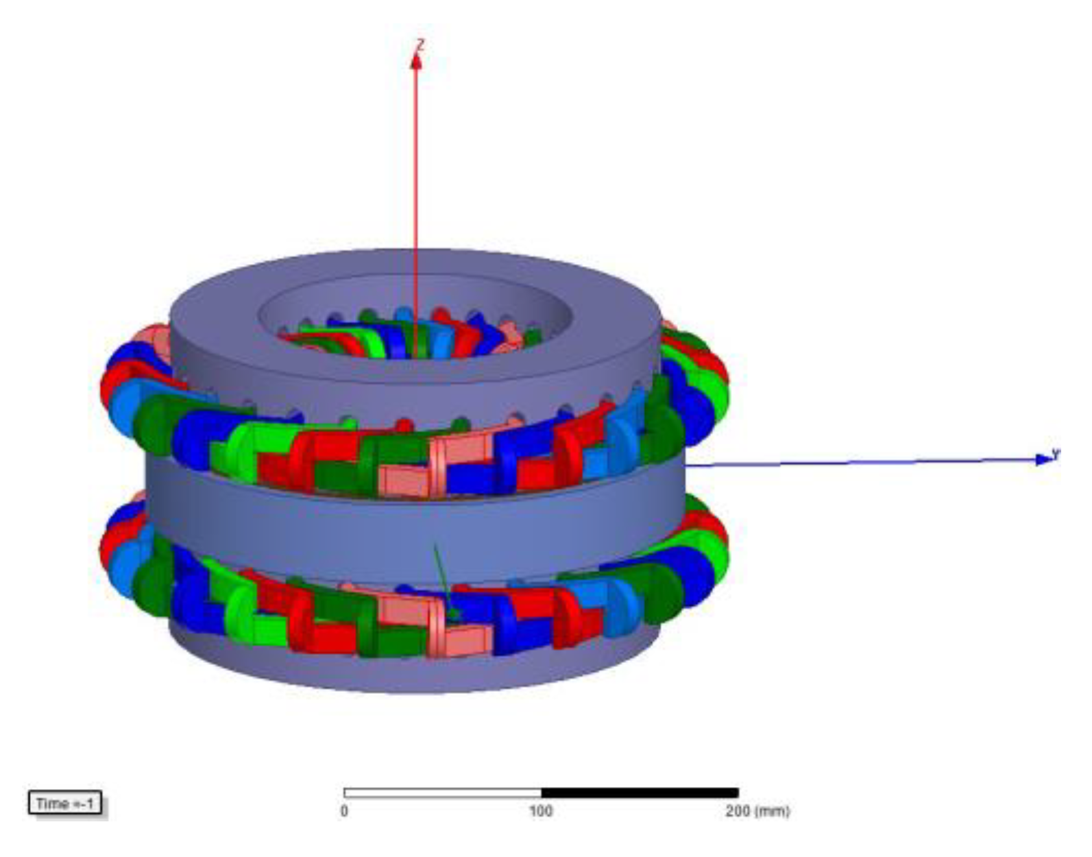
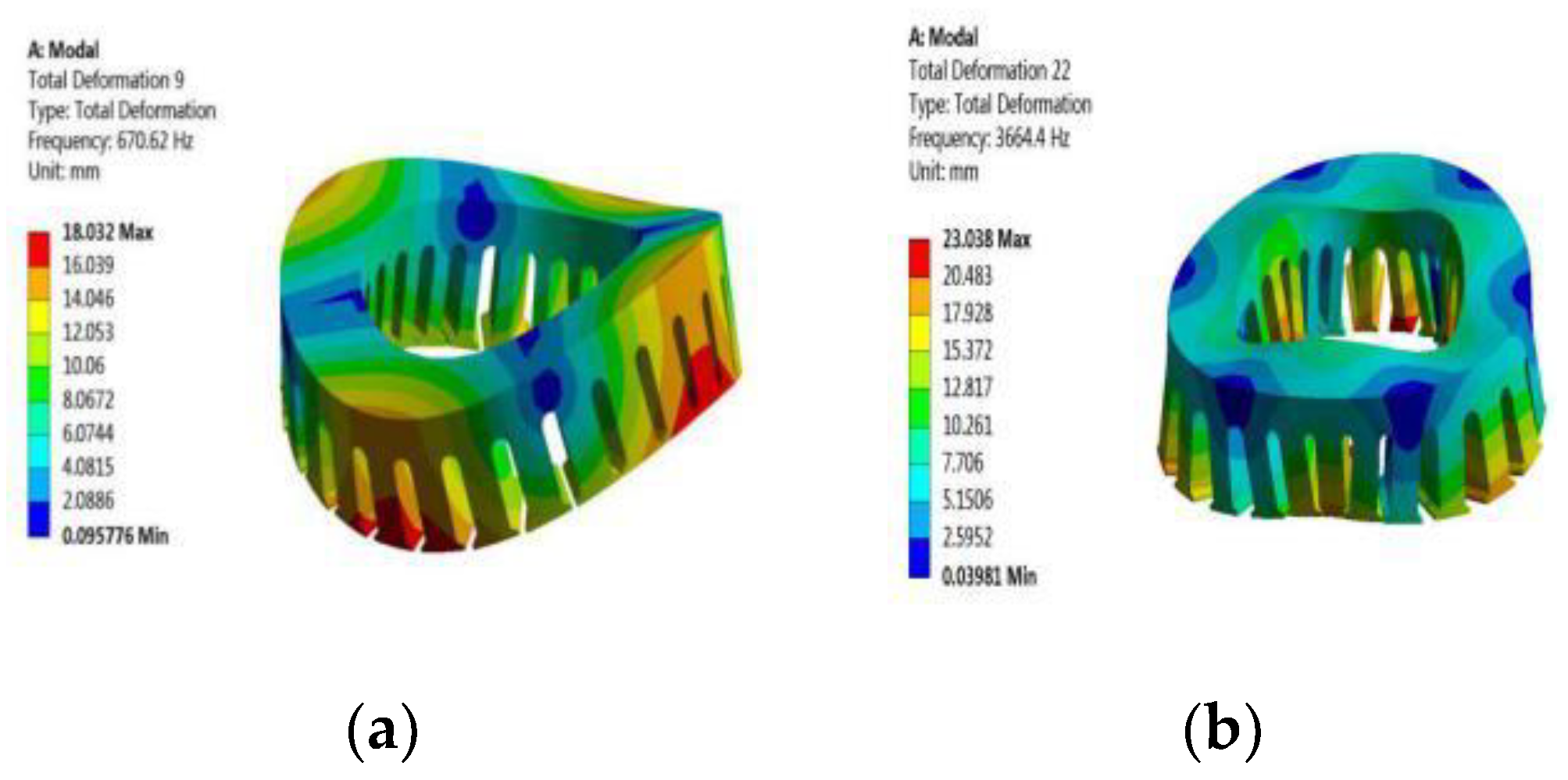
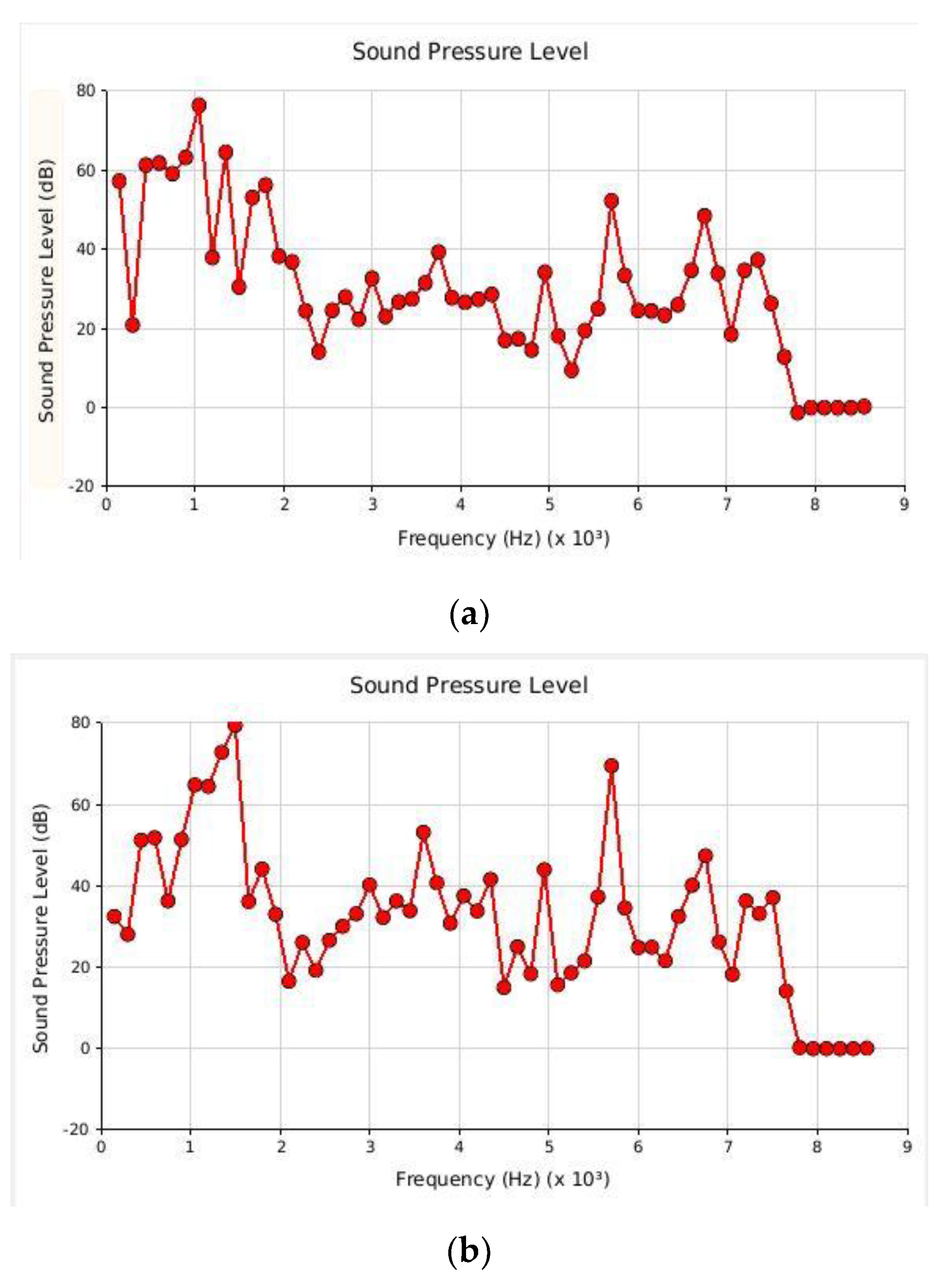
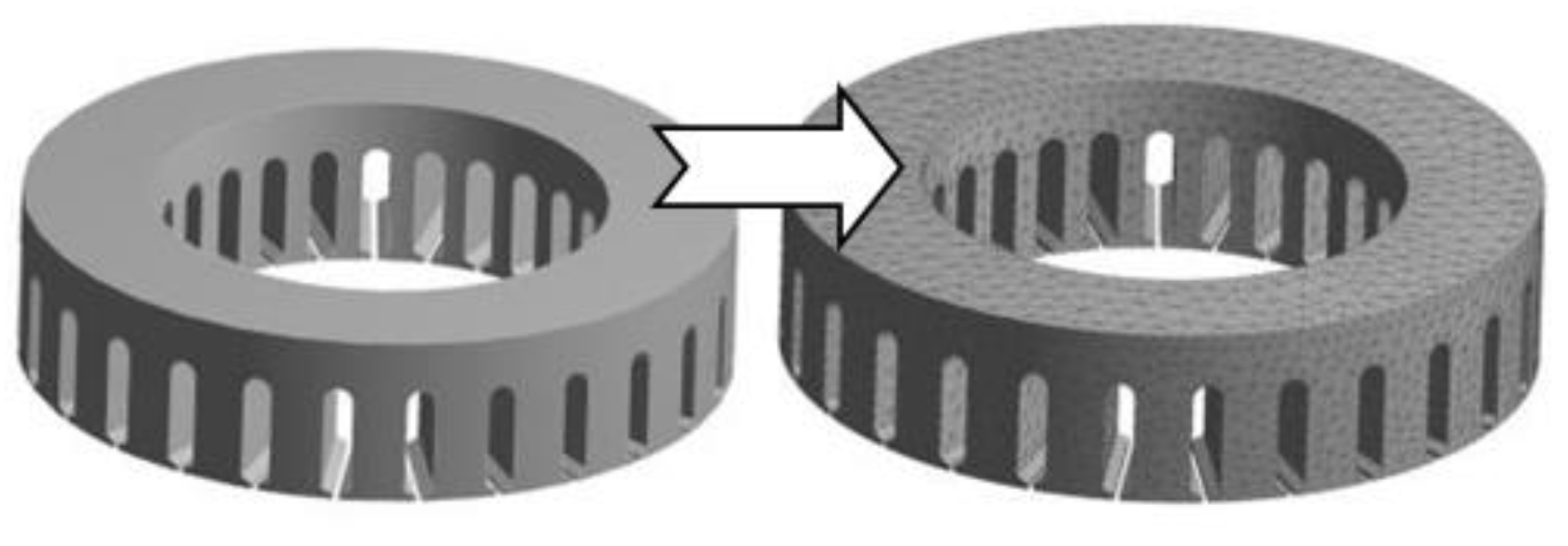
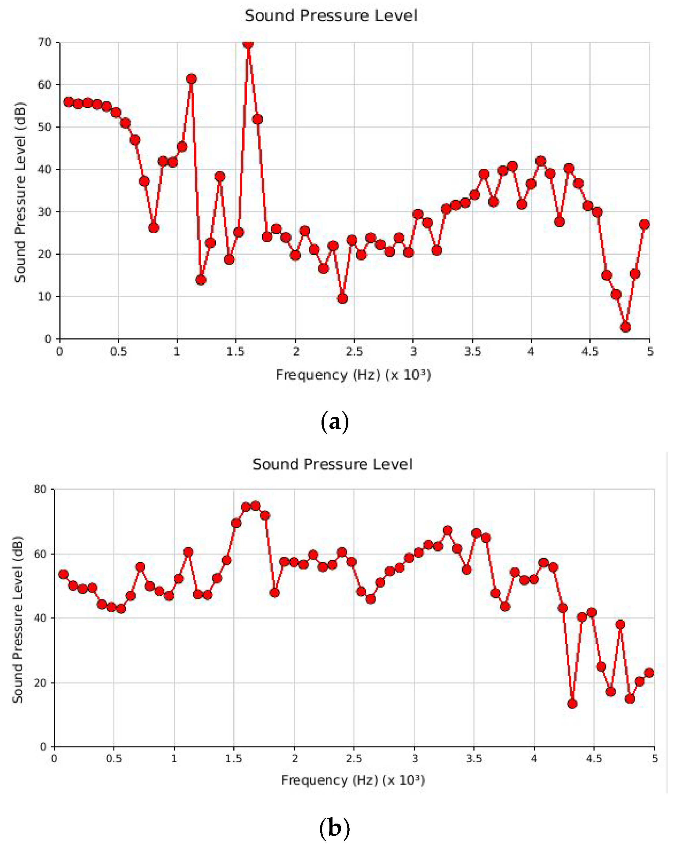
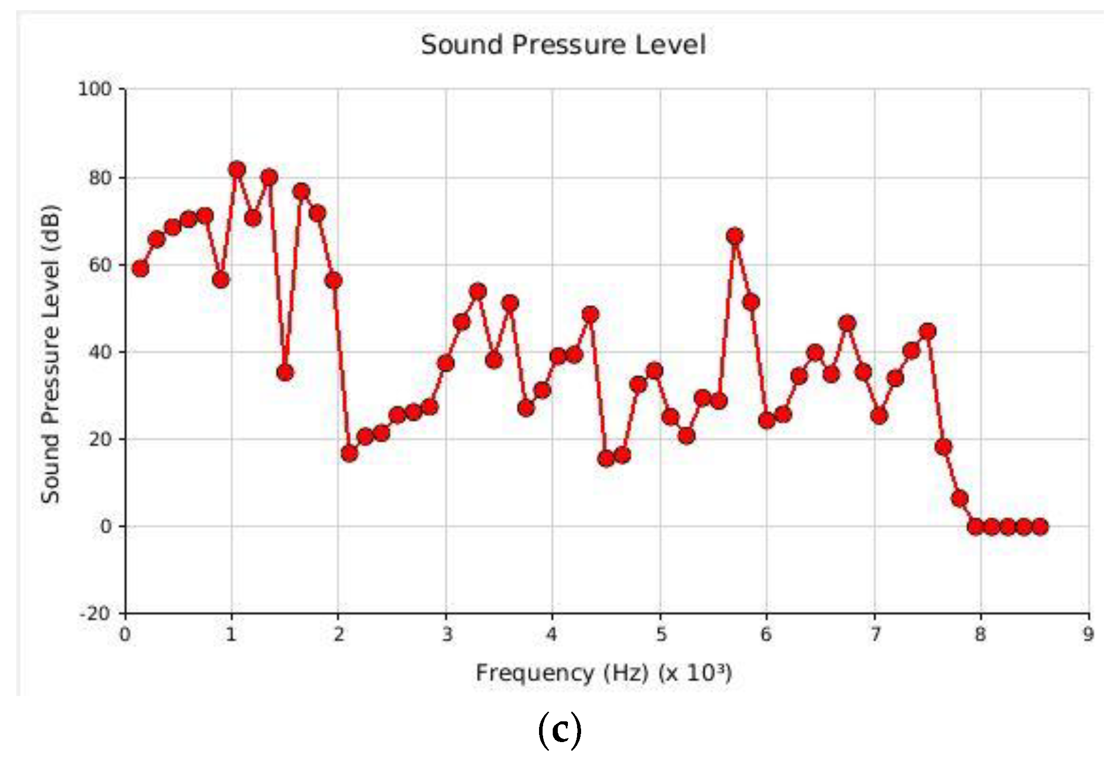
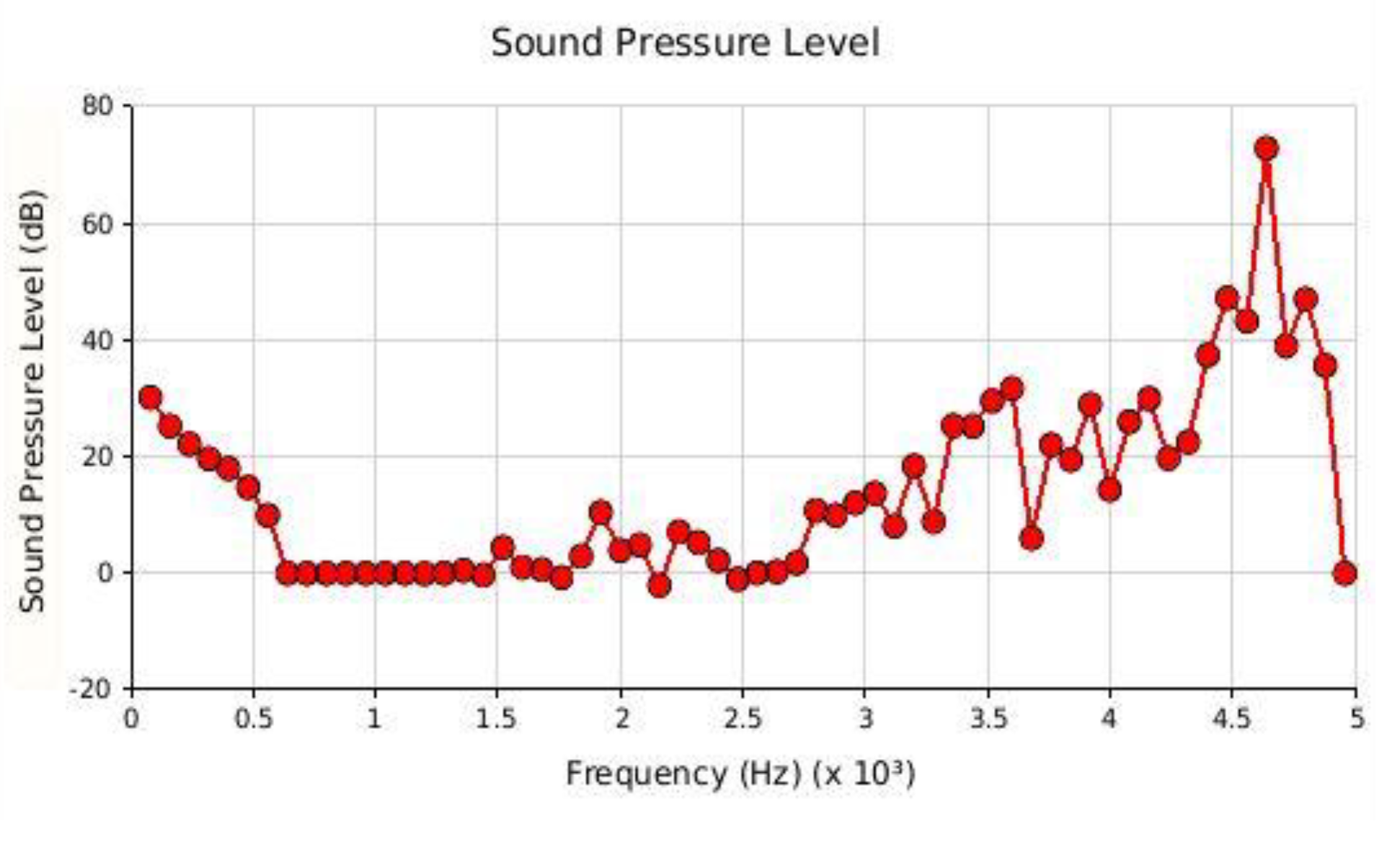
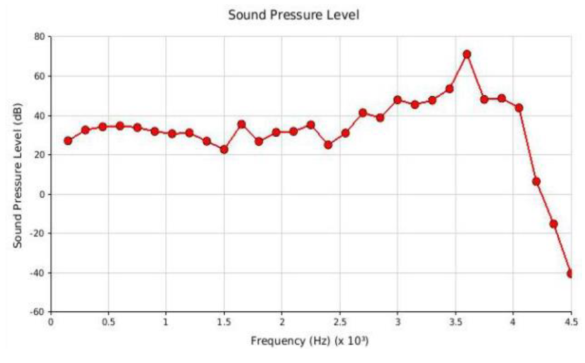
4.1. Electromagnetic Noise Generated by the AFPMSM Stator Structure
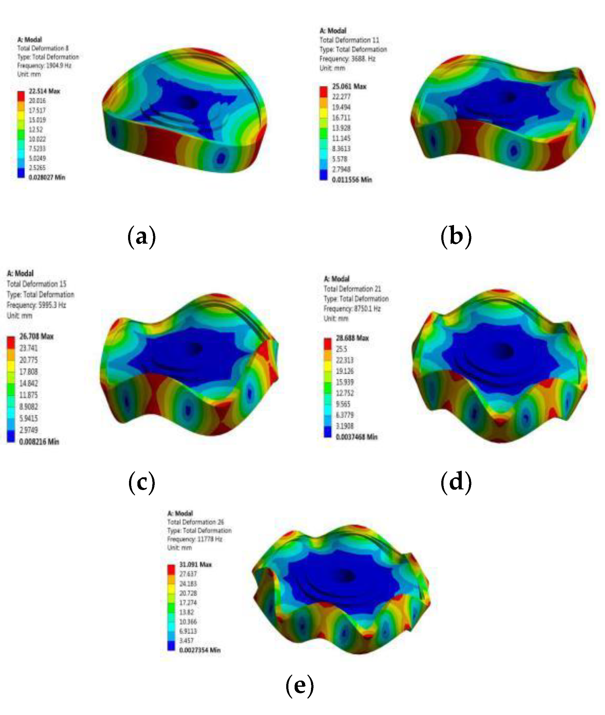
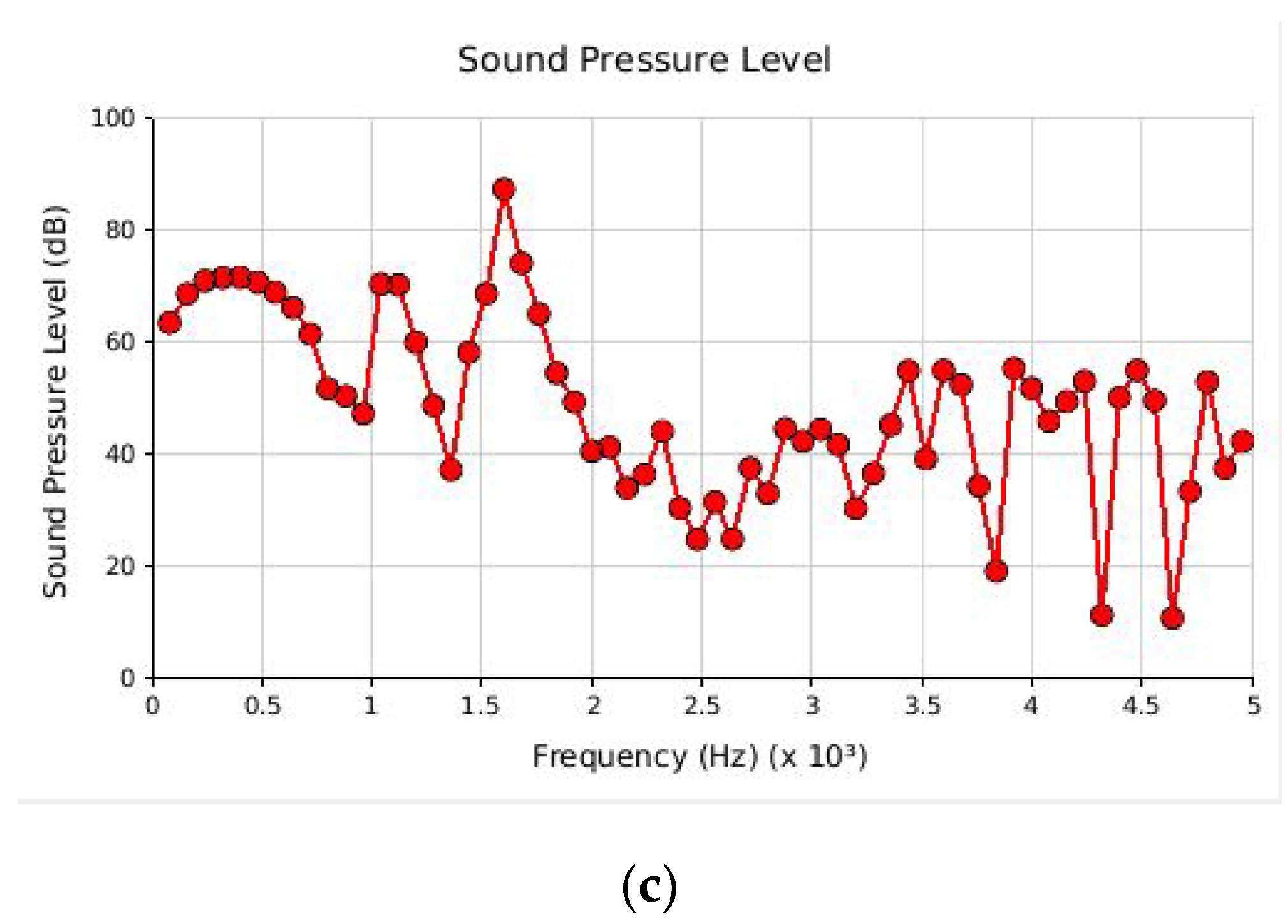
4.2. Electromagnetic Noise Generated by the AFPMSM Rotor Structure
5. Thermal Analysis of AFPMSM
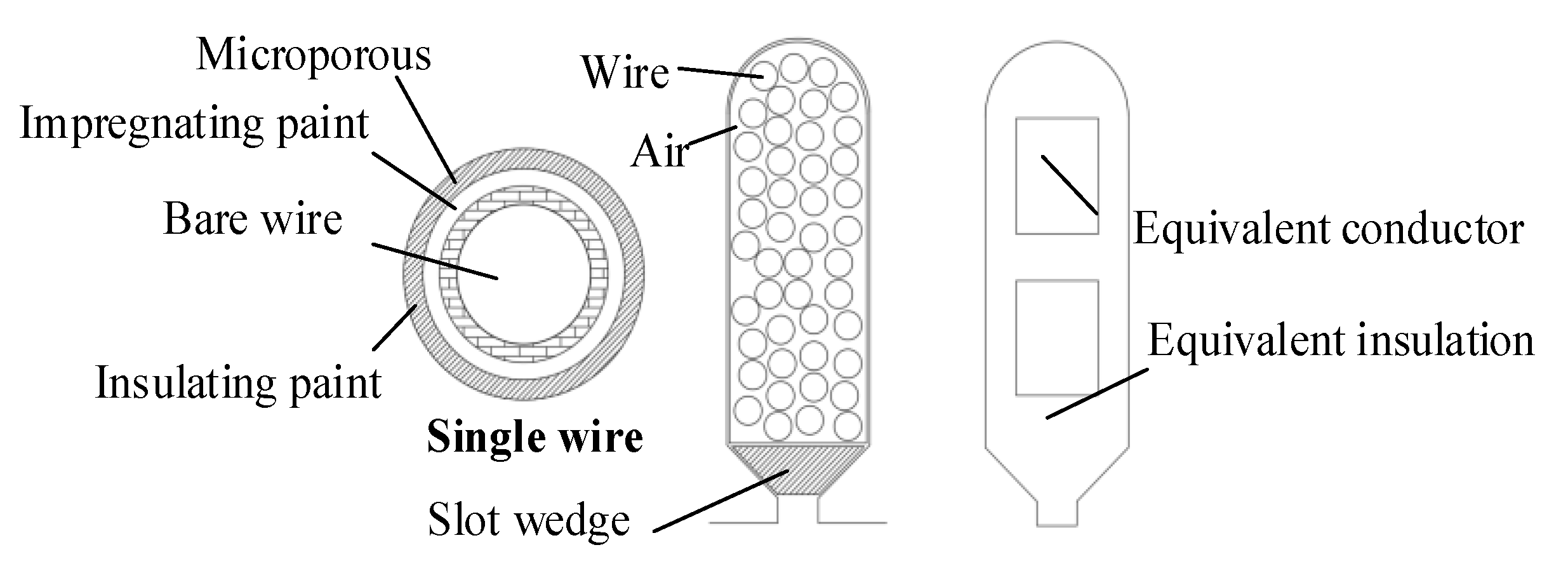
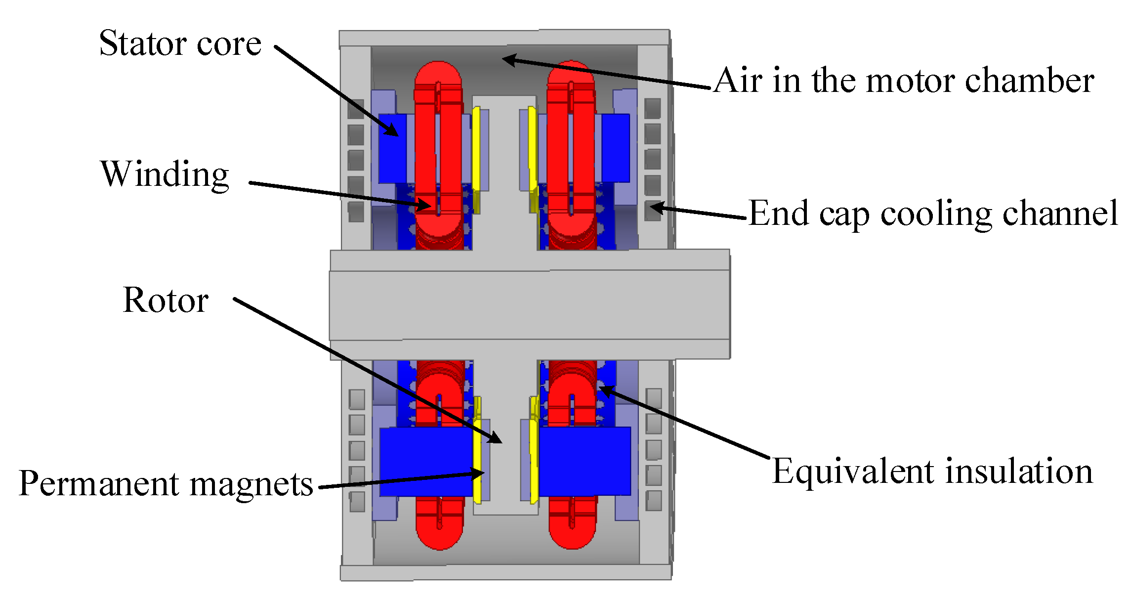
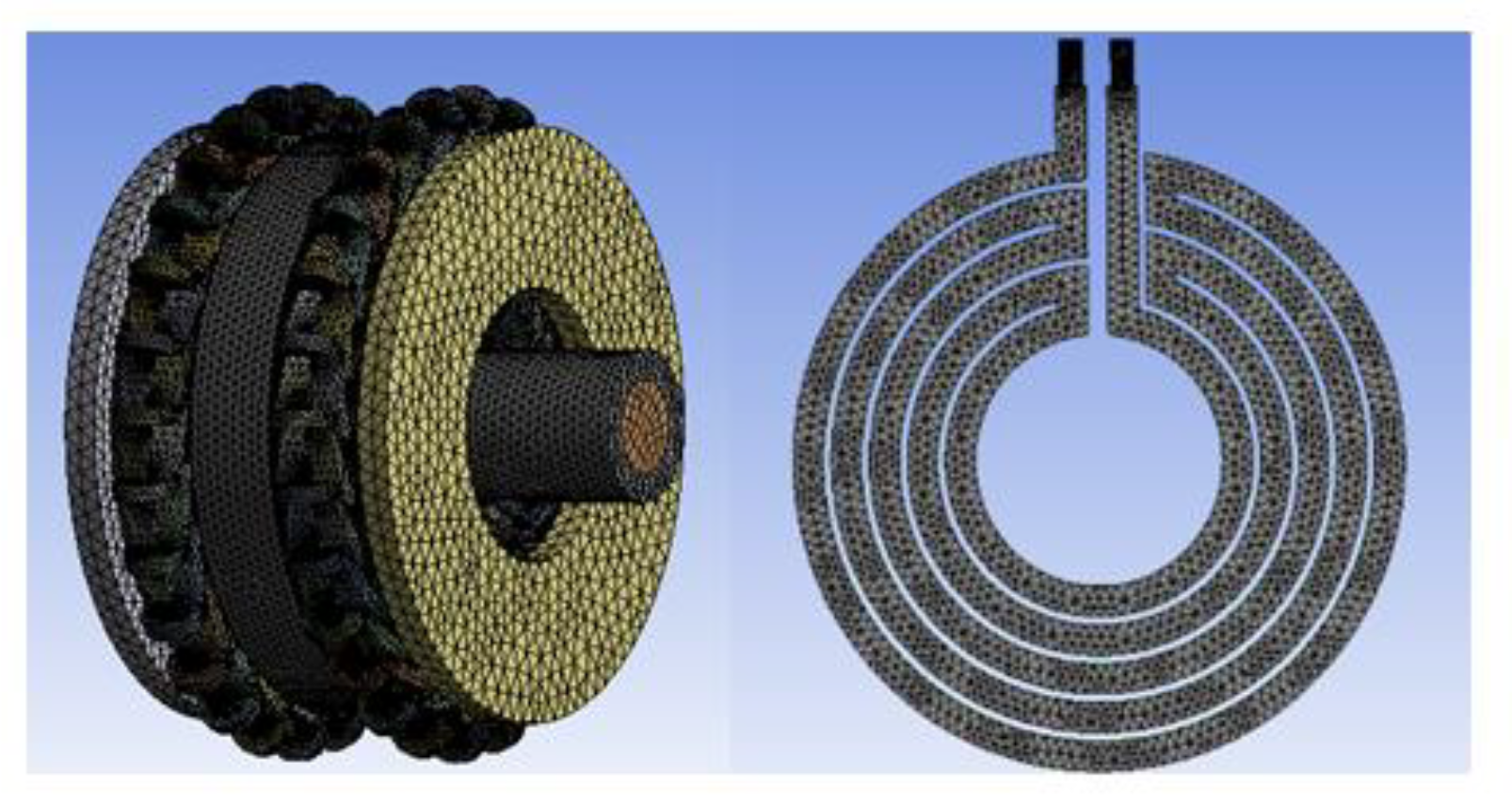
5.1. AFPMSM Temperature Field Equivalent Simplified Calculation Model
- The insulating paint of the winding is evenly distributed, and the winding is completely dip-coated;
- Since the inter-strand insulation of the armature windings cannot be completely considered and wound, the inner region of the stator slots is equivalently treated. The cross-sectional areas of the upper and lower windings are equal, and the thickness of the insulating layer, the windings and the left and right sides, and the windings of the windings and the upper and lower sides are equal;
- Ignoring radiation heat dissipation and contact thermal resistance between the rotor and the rotating shaft;
- The loss of each part of the motor does not change with temperature;
- The heat generated by the heat source is mainly carried away by the end cover cooling water, and the heat exchange between the outer surface of the casing and the surrounding air is negligible.
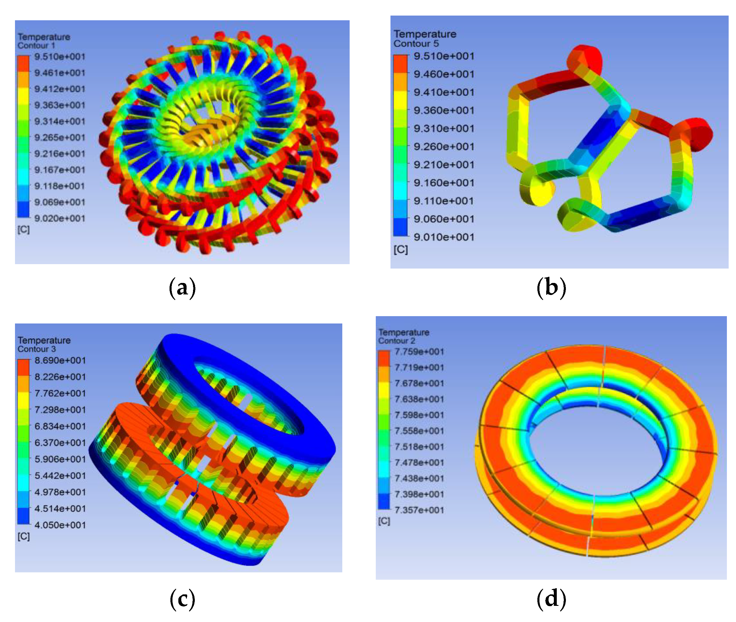
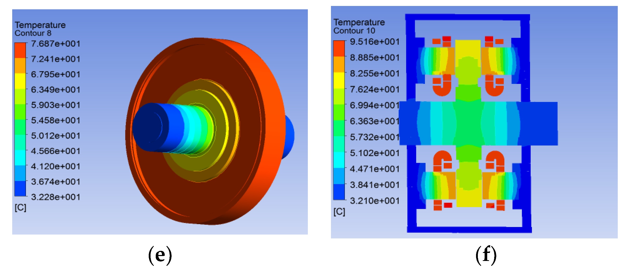
5.2. Temperature Field Analysis under AFPMSM Rated Conditions
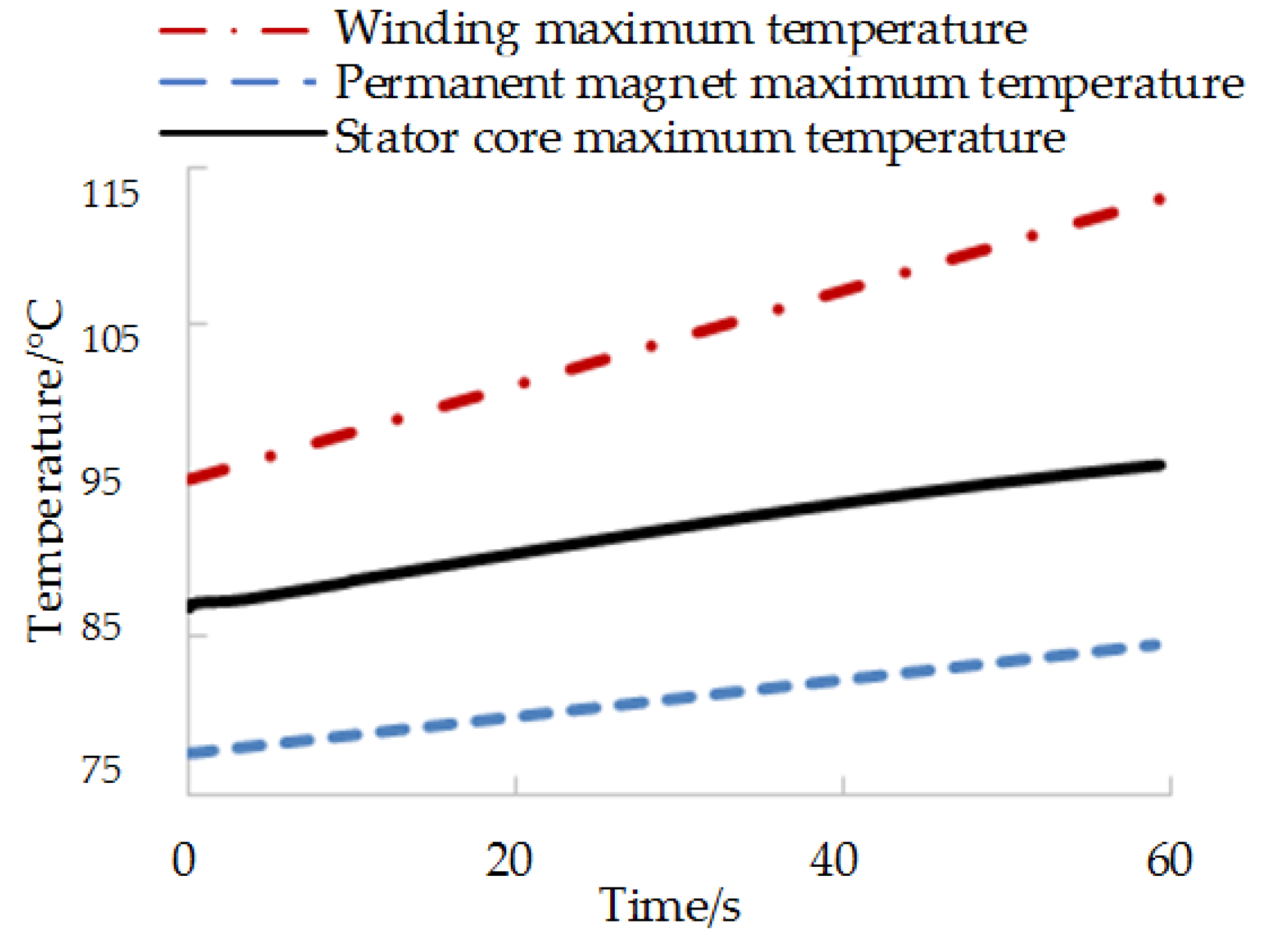
5.3. Temperature Field Analysis of AFPMSM under Peak Operating Conditions
6. Conclusions
- The electromagnetic design method based on the analytical method was used to analyze the key electromagnetic parameters such as air gap magnetic density harmonics, positioning torque and no-load back EMF of AFPMSM. The correctness of the analytical calculation was verified by 3D electromagnetic field simulation.
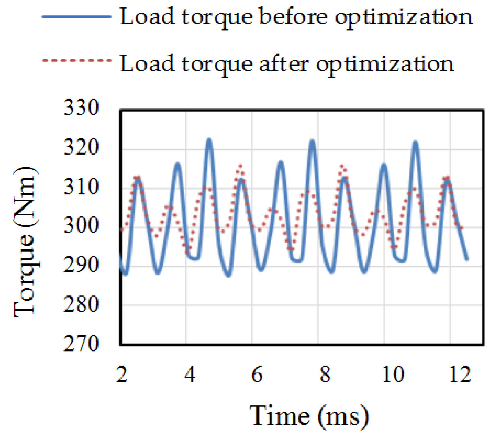
- The stator core was used to open the auxiliary slot to suppress the torque ripple, and the maximum torque ripple peak-to-peak value was reduced by 2%.
- Based on the multi-physics simulation software, the vibration and noise characteristics of the motor were analyzed from the electromagnetic force and the modal state. The electromagnetic noise characteristics of the no-load, rated load, and peak load operating points at different speeds were simulated. The noise, vibration and harshness (NVH) of the motor was verified.
- The thermal simulation based on fluid-structure coupling checked the temperature rise of the AFPMSM after the rated operating point reached the thermal steady state and transient operation for 1 min, which ensured the safety and reliability of the motor running under vehicle working conditions.
Author Contributions
Funding
Conflicts of Interest
References
- Chen, Y.; Zhang, B. Minimization of the Electromagnetic Torque Ripple Caused by the Coils Inter-Turn Short Circuit Fault in Dual-Redundancy Permanent Magnet Synchronous Motors. Energies 2017, 10, 1798. [Google Scholar] [CrossRef]
- Wang, W.; Wang, W. Compensation for Inverter Nonlinearity in Permanent Magnet Synchronous Motor Drive and Effect on Torsional Vibration of Electric Vehicle Driveline. Energies 2018, 11, 2542. [Google Scholar] [CrossRef]
- Pietrusewicz, K.; Waszczuk, P.; Kubicki, M. MFC/IMC Control Algorithm for Reduction of Load Torque Disturbance in PMSM Servo Drive Systems. Appl. Sci. 2019, 9, 86. [Google Scholar] [CrossRef]
- Jia, Y.F.; Chu, L.; Xu, N.; Li, Y.K.; Zhao, D.; Tang, X. Power Sharing and Voltage Vector Distribution Model of a Dual Inverter Open-End Winding Motor Drive System for Electric Vehicles. Appl. Sci. 2018, 8, 254. [Google Scholar] [CrossRef]
- Wang, R.J. Optimal design of a coreless stator axial flux permanent-magnet generator. IEEE Trans. Magn. 2005, 41, 55–64. [Google Scholar] [CrossRef]
- Aydin, M.; Huang, S.; Lipo, T.A. Torque quality and comparison of internal and external rotor axial flux surface-magnet disc machines. IEEE Trans. Ind. Electron. 2006, 53, 822–830. [Google Scholar] [CrossRef]
- Zhao, J.F.; Hua, M.Q.; Liu, T.Z. Research on a Sliding Mode Vector Control System Based on Collaborative Optimization of an Axial Flux Permanent Magnet Synchronous Motor for an Electric Vehicle. Energies 2018, 11, 3116. [Google Scholar] [CrossRef]
- Darba, A.; Esmalifalak, M.; Barazandeh, E.S. Implementing SVPWM technique to axial flux permanent magnet synchronous motor drive with internal model current controller. In Proceedings of the 2010 4th International Power Engineering and Optimization Conference, Shah Alam, Malaysia, 23–24 June 2010; pp. 126–131. [Google Scholar]
- Lim, D.K.; Cho, Y.S.; Ro, J.S.; Jung, S.Y.; Jung, H.K. Optimal Design of an Axial Flux Permanent Magnet Synchronous Motor for the Electric Bicycle. IEEE Trans. Magn. 2016, 52, 1–4. [Google Scholar] [CrossRef]
- Kim, J.S.; Lee, J.H.; Kim, Y.J.; Jung, S.Y. Characteristics analysis method of axial flux permanent magnet motor based on 2-D finite element analysis. IEEE Trans. Magn. 2017, 53, 1–4. [Google Scholar] [CrossRef]
- Hemeida, A.; Sergeant, P. Analytical Modeling of Surface PMSM Using a Combined Solution of Maxwell–s Equations and Magnetic Equivalent Circuit. IEEE Trans. Magn. 2014, 50, 1–13. [Google Scholar] [CrossRef]
- Xia, C.; Zhao, J.; Yan, Y.; Shi, T. A novel direct torque control of matrix converter-fed PMSM drives using duty cycle control for torque ripple reduction. IEEE Trans. Ind. Electron. 2013, 61, 2700–2713. [Google Scholar] [CrossRef]
- Vafaie, M.H.; Dehkordi, B.M.; Moallem, P.; Kiyoumarsi, A. Minimizing torque and flux ripples and improving dynamic response of PMSM using a voltage vector with optimal parameters. IEEE Trans. Ind. Electron. 2015, 63, 3876–3888. [Google Scholar] [CrossRef]
- Wang, D.; Lin, H.; Yang, H.; Wang, K. Cogging torque optimization of flux memory pole-changing permanent magnet machine. IEEE Trans. Appl. Supercond. 2016, 26, 1–5. [Google Scholar] [CrossRef]
- Lai, C.; Feng, G.; Mukherjee, K.; Kar, N.C. Investigations of the influence of PMSM parameter variations in optimal stator current design for torque ripple minimization. IEEE Trans. Energy Convers. 2017, 32, 1052–1062. [Google Scholar] [CrossRef]
- Wahsh, S.; Shazly, J.; Yassin, A. Steady state heat conduction problems of AFPMSM using 3D Finite Element. In Proceedings of the 18th International Middle-East Power Systems Conference, Helwan Univ, ON, Egypt, 27–29 December 2016; pp. 949–953. [Google Scholar]
- Chen, Q.; Liang, D.; Gao, L.; Wang, Q.; Liu, Y. Hierarchical thermal network analysis of axial-flux permanent-magnet synchronous machine for electric motorcycle. IET Electr. Power Appl. 2018, 12, 859–866. [Google Scholar] [CrossRef]
- Rasekh, A.; Sergeant, P.; Vierendeels, J. Fully predictive heat transfer coefficient modeling of an axial flux permanent magnet synchronous machine with geometrical parameters of the magnets. Appl. Thermal Eng. 2017, 110, 1343–1357. [Google Scholar] [CrossRef]
- De Bisschop, J.; Sergeant, P.; Dupré, L. Demagnetization fault detection in axial flux PM machines by using sensing coils and an analytical model. IEEE Trans. Magn. 2017, 53, 1–4. [Google Scholar] [CrossRef]
- De Bisschop, J.; Sergeant, P.; Hemeida, A.; Vansompel, H.; Dupre, L. Analytical Model for Combined Study of Magnet Demagnetization and Eccentricity Defects in Axial Flux Permanent Magnet Synchronous Machines. IEEE Trans. Magn. 2017, 53, 1–12. [Google Scholar] [CrossRef]
- De Bisschop, J.; Abdallh, A.; Sergeant, P.; Dupré, L. Identification of Demagnetization Faults in Axial Flux Permanent Magnet Synchronous Machines Using an Inverse Problem Coupled With an Analytical Model. IEEE Trans. Magn. 2014, 50, 1–4. [Google Scholar] [CrossRef]
- Hemeida, A.; Sergeant, P.; Vansompel, H. Comparison of Methods for Permanent Magnet Eddy-Current Loss Computations With and Without Reaction Field Considerations in Axial Flux PMSM. IEEE Trans. Magn. 2015, 51, 1–11. [Google Scholar] [CrossRef]
- Scheerlinck, B.; De Gersem, H.; Sergeant, P. 3D Eddy-Current and Fringing-Flux Distribution in an Axial-Flux Permanent-Magnet Synchronous Machine with Stator in Laminated Iron or SMC. IEEE Trans. Magn. 2015, 51, 1–4. [Google Scholar] [CrossRef]
- Chen, Q.; Liang, D.; Jia, S.; Ze, Q.; Liu, Y. Loss Analysis and Experiment of Fractional-Slot Concentrated-Winding Axial Flux PMSM for EV Applications. In Proceedings of the 10th IEEE Annual Energy Conversion Congress and Exposition, Portland, ON, USA, 23–27 September 2018; pp. 4329–4335. [Google Scholar]
- Fei, W.; Luk, P.C.K. Torque ripple reduction of axial flux permanent magnet synchronous machine with segmented and laminated stator. In Proceedings of the 2009 IEEE Energy Conversion Congress and Exposition, San Jose, CA, USA, September 2009; pp. 132–138. [Google Scholar]
- Woolmer, T.; McCulloch, M. Analysis of the yokeless and segmented armature machine. In Proceedings of the 2007 IEEE International Electric Machines & Drives Conference, Antalya, Turkey, 3–5 May 2007; pp. 704–708. [Google Scholar]
- Aydin, M.; Huang, S.; Lipo, T. Axial flux permanent magnet disc machine: A review. In Proceedings of the Symposium on Power Electronics, Electrical Drives, Automation, and Motion (SPEEDAM), Capri, Italy, 16–18 June 2004; pp. 61–71. [Google Scholar]
- Hosseini, S.M.; Agha-Mirsalim, M.; Mirzaei, M. Design, prototyping, and analysis of a low cost axial-flux coreless permanent-magnet generator. IEEE Trans. Magn. 2008, 44, 75–80. [Google Scholar] [CrossRef]


| Motor Parameters | Symbol | Value |
|---|---|---|
| Pole-pairs | p | 6 |
| Slot number | Q | 27 × 2 |
| Air gap length | δ | 1 mm |
| Rated torque | TN | 300 Nm |
| Rated power | PN | 50 kW |
| Stator outer diameter | Dso | 250 mm |
| Phase number | m | 3 |
| Rated speed | n | 1600 rpm |
| Permanent magnet Remanence | Br | 1.089 T |
| Coercivity | HC | 2 A/m |
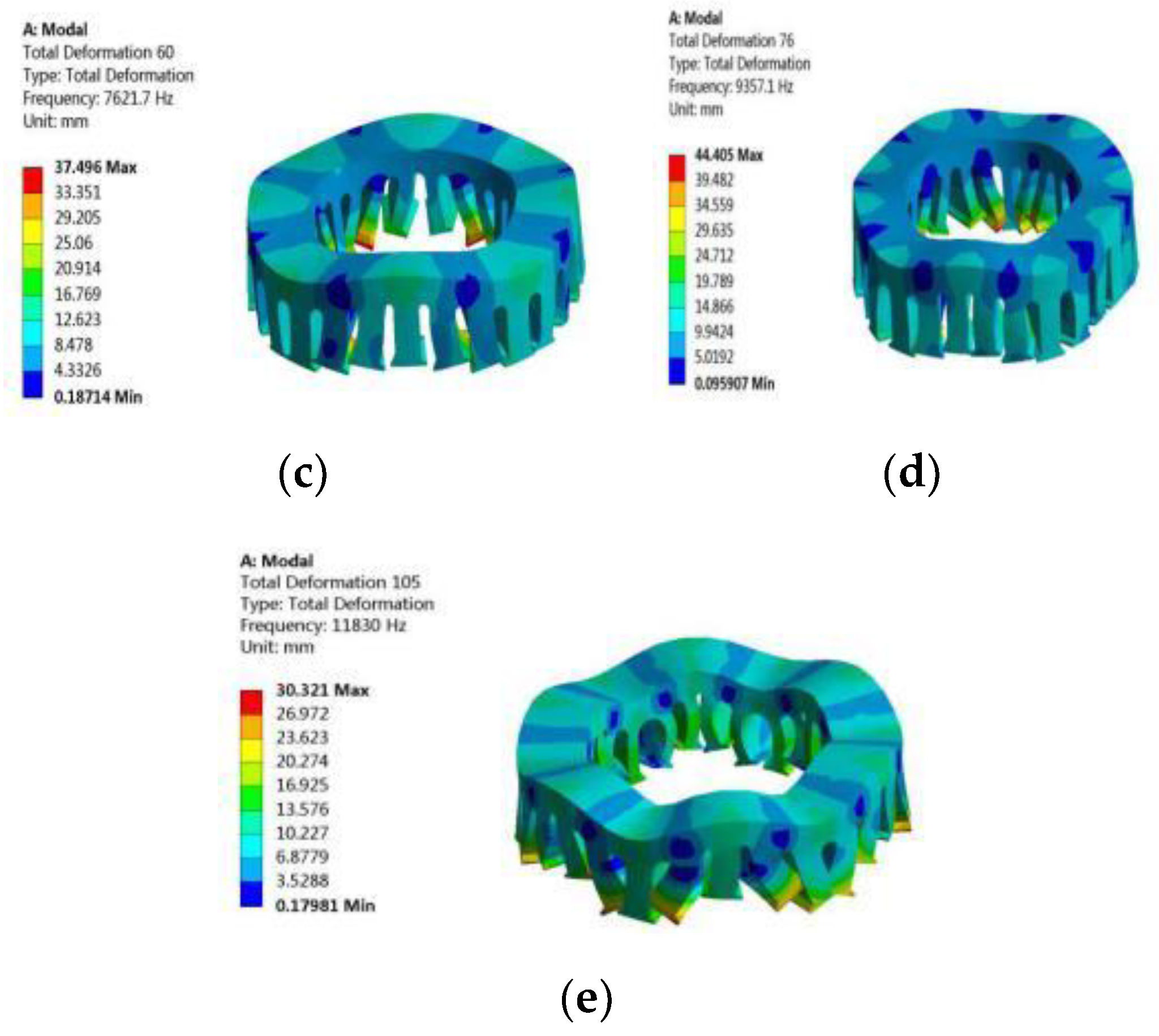
| Modal Order | Order 2 | Order 3 | Order 4 | Order 5 | Order 6 |
|---|---|---|---|---|---|
| Frequency | 671 | 3664 | 7621 | 9357 | 11,830 |
© 2019 by the authors. Licensee MDPI, Basel, Switzerland. This article is an open access article distributed under the terms and conditions of the Creative Commons Attribution (CC BY) license (http://creativecommons.org/licenses/by/4.0/).
Share and Cite
Zhao, J.; Han, Q.; Dai, Y.; Hua, M. Study on the Electromagnetic Design and Analysis of Axial Flux Permanent Magnet Synchronous Motors for Electric Vehicles. Energies 2019, 12, 3451. https://doi.org/10.3390/en12183451
Zhao J, Han Q, Dai Y, Hua M. Study on the Electromagnetic Design and Analysis of Axial Flux Permanent Magnet Synchronous Motors for Electric Vehicles. Energies. 2019; 12(18):3451. https://doi.org/10.3390/en12183451
Chicago/Turabian StyleZhao, Jianfei, Qingjiang Han, Ying Dai, and Minqi Hua. 2019. "Study on the Electromagnetic Design and Analysis of Axial Flux Permanent Magnet Synchronous Motors for Electric Vehicles" Energies 12, no. 18: 3451. https://doi.org/10.3390/en12183451
APA StyleZhao, J., Han, Q., Dai, Y., & Hua, M. (2019). Study on the Electromagnetic Design and Analysis of Axial Flux Permanent Magnet Synchronous Motors for Electric Vehicles. Energies, 12(18), 3451. https://doi.org/10.3390/en12183451