Article

A Study on the Heating Method and Implementation of a Shrink-Fit Tool Holder

1
School of Electrical Engineering, Zhejiang University of Water Resources and Electric Power, Hangzhou 310018, China
2
College of Mechanical and Electrical Engineering, China Jiliang University, Hangzhou 310018, China
*
Author to whom correspondence should be addressed.
Energies 2019, 12(18), 3416; https://doi.org/10.3390/en12183416
Submission received: 16 July 2019 / Revised: 3 September 2019 / Accepted: 4 September 2019 / Published: 4 September 2019
(This article belongs to the Section F: Electrical Engineering)

Abstract

:
A novel induction heating coil is proposed and designed as a shrink-fit tool holder. An electromagnetic field analysis of the coil with different winding methods is conducted using the ANSYS finite element analysis software and an appropriate coil structure is determined, based on the simulated electromagnetic field distribution cloud maps. The magnetic field in the X–Y plane is increased by one order of magnitude around the surface with the addition of the designed magnetic slot, as well as improving the magnetic leakage. The electromagnetic field strength in the middle of the coil is greatly increased, up to 2.312 × 10⁴ A/m, by the addition of a designed magnetic ring covering the top of the coil. The distribution of the three-dimensional temperature field is obtained by the ANSYS workbench transient thermal analysis software, based on the selected coil. Hot-loading equipment used for shrink-fit tool holders are implemented with diameter-selection, power, and heating time-setting functions. Experiments on different types of tool holders are carried out to obtain optimal heating parameters and to verify the reliability of the implemented heating equipment. Through experimental testing, the inserting and pulling out temperature is found to be about 270 °C for the BT40-SF06 and about 285 °C for the BT40-SF10. According to the experimental results, the simulated temperature field is in good agreement with the measured result. The optimal heating parameters of the heating equipment are determined, which proves the correctness of the heating method of the shrink-fit tool holder.

1. Introduction

The tool holder is one of the most important parts in the field of high-speed cutting. At present, three types of tool holder are widely used in industrial production: static pressure expansion, stress-locking, and shrink-fit tool holders [1,2,3]. Compared to static pressure expansion tool holders and stress-locking tool holders, the clamp of a shrink-fit tool holder is based on the thermal expansion and contraction principle, where there is a difference between the expansion coefficient of the tool holder and the cutter [4,5]. Due to electromagnetic induction heating, the environmental pollution is smaller and tool loading and unloading is simple, fast, and safe. The tool change time is generally less than 10 seconds, with a strong clamping force, high rigidity, and high balance [6,7,8]. Therefore, shrink-fit tool holders have been more and more widely used in the field of high-speed cutting.
The heating methods used in shrink-fit tool holders are electromagnetic induction and direct hot air blowing [9]. The electromagnetic induction heating method has efficient features: the heating process is fast and operation is relatively simple, as compared to hot air direct blowing methods [10]. Therefore, it is extremely important to develop a heat shrinking machine that can be applied to shrink-fit tool holders made of different materials. Chen and Li [11] pointed out that the shrink-fit tool holder is a new tool-clamping system suitable for high-precision machining, and introduced its working principles, heating–cooling equipment, and applications. That work mainly focused on the specific performance of the tool holder and parameter identification of the joint between the tool holder and the cutter. Cheng and several other authors [12] simplified the shrink-fit tool holder cutter combination into a parallel-connected spring-damping model using the finite element method. The parameters of the shrink-fit tool holder tool combination were identified, and the stiffness and damping parameters of each position in the joint were obtained. In [13], a cutting experiment showed that the radial rigidity of a shrink-fit tool holder is only 75.8% of that of a stress-locking tool holder. In [14], the contact deformation displacement and contact effective stress calculations for a shrink-fit tool holder under different conditions were carried out. The spindle-tool holder joint and the tool holder-cutter combination in the spring-damping model at the endpoint was simplified, and the finite difference and experimental measurements have been combined to identify the joint [15]. In [16], the inductive heating performance, thermal fatigue mode, and thermal fatigue life of an HSK (Hohl Shaft Kegel) shrink-fit tool holder were studied using the finite element method and an orthogonal test. In [17], a temperature field model of 45 steel induction heating hot-storing tool was established, and the relationships between temperature, coil current, and heating time were analyzed. In summary, the research has been focused on the use of shrink-fit tool holder in tool holding applications, as well as the matching performance of the cutter [18]. However, there have been few studies on the structure, material, and induction heating process of shrink-fit tool holders.
The difficulty inherent to a shrink-fit tool holder is that, in order to achieve a successful replacement of the cut, the surface and top of the shank-fit tool holder must be heated the fastest. In this paper, a method is proposed to enhance the electromagnetic field generated by the electromagnetic induction heating coil on the top and surface of the shank-fit tool holder, where the magnetic field strength is increased by 10 times, the magnetic field distribution is more uniform, and the magnetic field leakage is significantly improved. The above goals were achieved in three steps: the first is a novel winding method of the induction heating coil, which is adopted to enhance the electromagnetic field strength around the surface and the top of the shrink-fit tool holder, based on the ANSYS Maxwell finite element analysis. Second, a magnetic slot is designed to wrap the coil in order to further enhance the magnetic field strength around the surface of the shrink-fit tool holder and to reduce magnetic field leakage. Finally, a magnetic ring is designed to cover the top of the coil.
The structure of this paper is as follows: Section 2 introduces the working principle of the shrink-fit tool holder. Section 3 introduces the process of electromagnetic field mode establishment and electromagnetic field simulation. Section 4 briefly introduces the overall structure of heat-loading tool holder equipment. Section 5 presents the experimental data analysis. Finally, Section 6 is a summary and future vision.

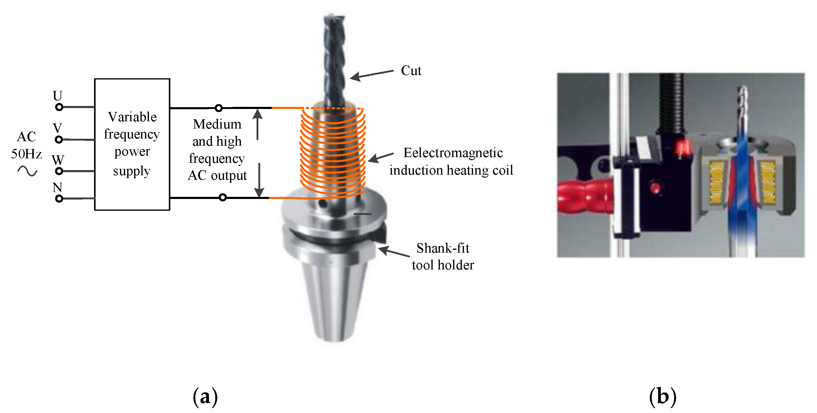
2. The Principle of the Shrink-Fit Tool Holder

The working principle of a shrink-fit tool holder is the thermal expansion and contraction of the material. In the original state, where the hole diameter of the tool holder is smaller than the diameter of the cutter, the cutter cannot be directly inserted into the tool holder. Once it is heated by the heat-loading equipment, the hole of the tool holder is thermally expanded, and the diameter of the tool holder is gradually increased, such that the cutter can be inserted. When the cutter is taken out, based on the same principle, the difference in expansion coefficient between the tool holder and the cutter is the key to realizing hot loading, as the degree of expansion of the tool holder is greater than the degree of expansion of the cutter and, so, the cutter can be removed smoothly.
The electromagnetic induction heating diagram and cross-section of the coil structure are shown in Figure 1. The principle of electromagnetic induction heating of a shrink-fit tool holder is that, when a high frequency alternating current generates an electromagnetic field through the induction coil, the internal magnetic lines form a loop through the clamping part of shrink-fit tool holder. Then, an induced eddy current is generated on the surface and inner wall of the clamping part, which causes the tool holder to heat rapidly. The conversion of electrical energy to thermal energy is finished. The whole energy conversion process involves four effects: The eddy current effect, skin effect, proximity effect, and ring effect [19,20,21].
When the eddy current flows inside the conductor, it will cause loss resulting in the self-heating of the conductor. Therefore, the eddy current effect has a thermal effect. The average power P consumed by the eddy current on the conductor can be expressed as:
P = ρ ( 2 π f ) 2 B max 2 V ,
where the ρ is the resistivity of the material (Ω∙m), f is the current frequency (Hz), Bmax is the largest magnetic induction in the conductor (Wb/m2), and V is the effective volume of the conductor (m3) [22].
Generally, it is stipulated that, when the eddy current intensity decreases from the surface to the inner layer to a value equal to 1/e (36.8%) of the maximum eddy current intensity, the distance δ from the surface to the inner layer is called the current penetration depth [23]. The heat generated by the eddy current is proportional to the square of the eddy current intensity, so the heat drop from the surface to the inner layer is much faster than the eddy current drop rate. It can be considered that 85–90% of the heat is concentrated on the surface to the inside. The skin depth δ is given by:
δ = ρ π μ 0 μ r f ,
where μ0 is the vacuum permeability and μr is the relative permeability [24]. It can be seen, from Equation (2), that the skin depth δ of the workpiece is related to μr and f. The value of δ decreases as f increases under known ρ and μr and, thus, the skin effect is more obvious. Therefore, when designing the induction coil, if the load of the whole system and the material properties of the heated workpiece are known, the appropriate penetration depth is selected, according to the skin effect and working frequency, to minimize the loss of the coil itself.
In order to realize the function of the heat-loading tool holder equipment, the tool holder is required to be heated to 300 °C to realize the insertion and extraction of the cutter, based on multiple experiments. According to the specific heat capacity, the heat required for the tool holder to reach 300 °C can be obtained as:
Q = c × m × Δ T ,
where c is the specific heat capacity (J/(kg∙K)), m is the material quality (kg), and Δ T is the temperature change (K). The BT40-SF06-90 and BT40-SF10-90 tool holders were selected for the experimental test. Physical photos and a structural diagram of these shrink-fit tool holders are shown in Figure 2 and the parameters of the shrink-fit tool holders are listed in Table 1. The clamping part of the tool holder can be approximated as a cylinder with a certain taper, where m can be obtained as:
m = ρ material × { 1 3 π h [ ( D 1 2 ) 2 + ( D 2 2 ) 2 + D 1 2 D 2 2 ] π h ( d m 2 ) 2 } ,
where ρmaterial is the density of 4Cr5MoSiV1 (which is about 7850 kg/m3). The value of m was calculated to be 178.5 g for the BT40-SF×10-90 tool holder, based on the Equation (4). Therefore, c was about 0.55 kJ/(kg °C) at 300 °C, the heat required to raise the tool holder from 20 °C to 300 °C was obtained by Equation (3), and Q was about 27,489 J.
The value (D2–D1) was equal to 8 mm for the BT40-SF×10-90 tool holder; the critical frequency of induction heating is defined as the heating frequency when (D2–D1) is approximately equal to four times the penetration depth, so the value of δ was 2mm. According to the design principle of the induction heating device, the clamping part of the tool holder can be regarded as a through-heating workpiece, at this time. Based on Equation (2), the critical frequency (fc) could be obtained as:
f c = 16 ρ / [ π × μ 0 × μ r × ( D 2 D 1 ) 2 ] ,
where ρ was about 36 × 10−6 Ω·m and μr was 450 at 300 °C. Thus, fc was calculated to be about 5.0 kHz. The current frequency was designed to range from 5 kHz to 20 kHz for the shrink-fit tool holder, and δ was (1/8–1/4)(D2–D1).

3. Establishment of Electromagnetic Field Mode and Electromagnetic Field Simulation

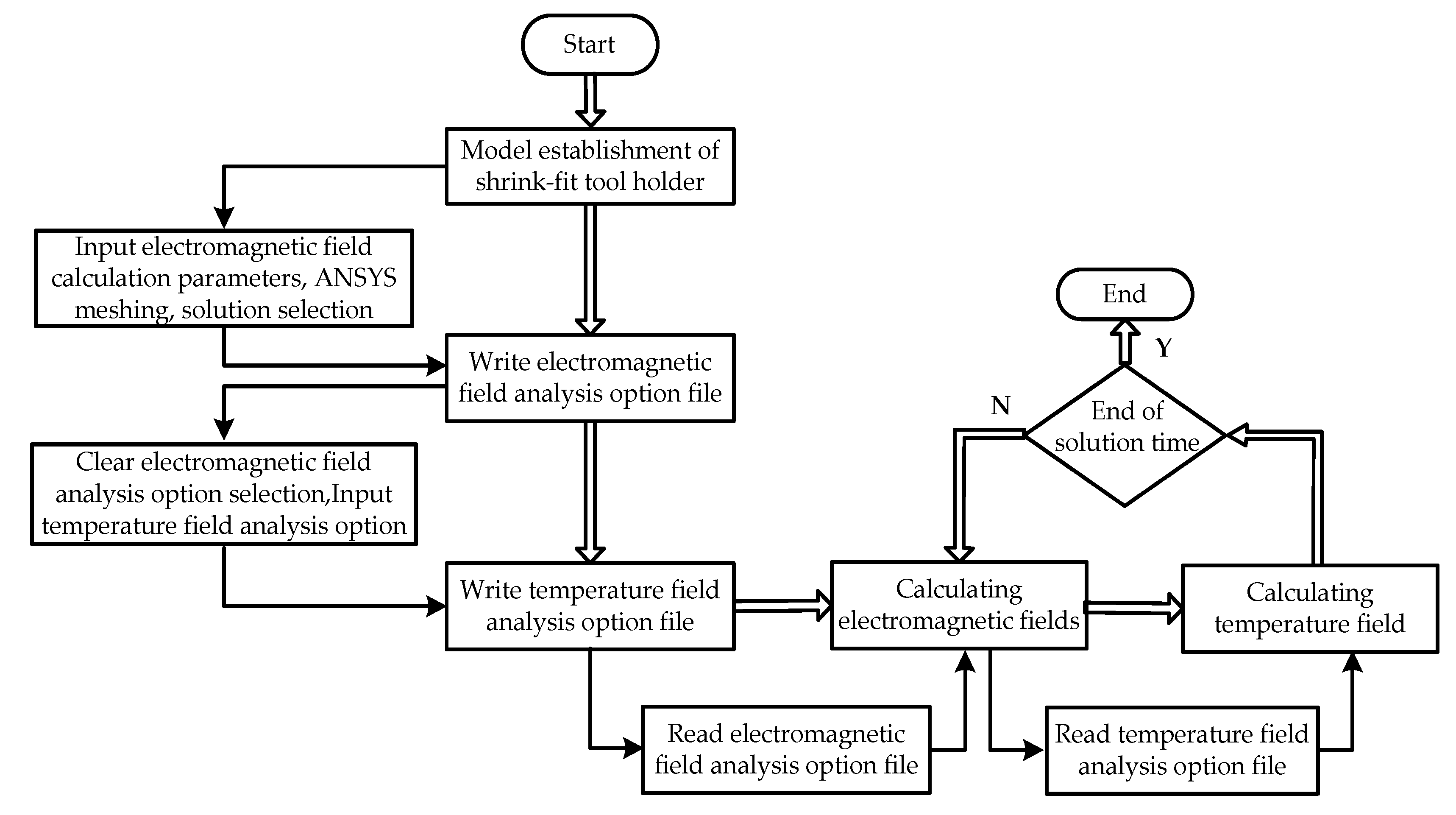
3.1. Establishment of Electromagnetic Field Model of Shrink-Fit Tool Holder

In the induction heating structure shown in Figure 1, H ( r ) and E ( r ) are defined as the magnetic field strength vector and electric field strength vector, respectively, at a certain point from the axial radius r of the workpiece. If the edge effect is neglected, the medium is isotropic and uniform and the internal magnetic field intensity of the coil is a harmonic function of time. Then, the time-varying magnetic field is written as:
× H ( r ) = J ( r ) = σ E ( r )
× E ( r ) = μ H ( r ) t
H ( r t ) = H ( r ) e j ω t ,
where J ( r ) is the current density vector, with r ( 0 ,   D 2 / 2 ) ; σ is the conductivity; and μ and ω are the permeability and angular frequency, respectively.
Considering the symmetry of the magnetic field distribution in a cylindrical workpiece, the cylindrical co-ordinate system (r, z, θ) was used to analyze the magnetic field distribution in the shrink-fit tool holder. The equations can be obtained as:
H ( r ) = H ( r ) e z
× H ( r ) = d H ( r ) d r e θ
2 × H ( r ) = [ 1 r d H ( r ) d r d 2 H ( r ) d r 2 ] e z ,
where the e z and e θ are the unit vectors of the respective column co-ordinates.
Based on Equations (6)–(11), Equation (12) can be obtained as:
d 2 H ( r ) d ( k r ) 2 + 1 k r d H ( r ) d k r H ( r ) = 0 ,
where k2 = jωσμ. Equation (12) is a Bessel function and, so, the general solution of Equation (12) can be written as:
H ( r ) = A I 0 ( k r ) + B K 0 ( k r ) ,
where I 0 ( k r ) is the first type of zeroth-order Bessel function, K 0 ( k r ) is the second type of zeroth-order Bessel function, and A and B are undetermined coefficients. The boundary conditions are given as:
{ I 0 ( 0 ) = 0   and   K 0 ( 0 )   when   r 0   H ( R ) = H 0   when   r R ,
where H0 is the magnetic field strength of the workpiece surface and R = D2/2. Then, A = H 0 / I 0 ( k R ) and B = 0, based on Equations (13) and (14).
Based on Equations (6) and (9), H ( r ) and J ( r ) can be obtained as:
{ H ( r ) = H 0 I 0 ( k r ) I 0 ( k R ) e z J ( r ) = σ E ( r ) = k H 0 I 1 ( k r ) I 1 ( k R ) e θ .
It can be seen, from Equation (15), that the variation law of the electromagnetic field is same as the eddy current density in the workpiece. When r approaches R, H ( r ) , E ( r ) and J ( r ) increase rapidly with increasing r and, when r = 0, H ( r ) , E ( r ) , and J ( r ) are close to zero, which indicates the skin effect of the eddy current. This shows that, in the induction heating process, the closer the heated workpiece is to the surface layer, the greater the eddy current density is, and more eddy current heat is generated. Furthermore, the electromagnetic field, electric field, and eddy current density distribution in the workpiece have almost the same change rule; thus, the higher the coil operating frequency, the more obvious the skin effect is.

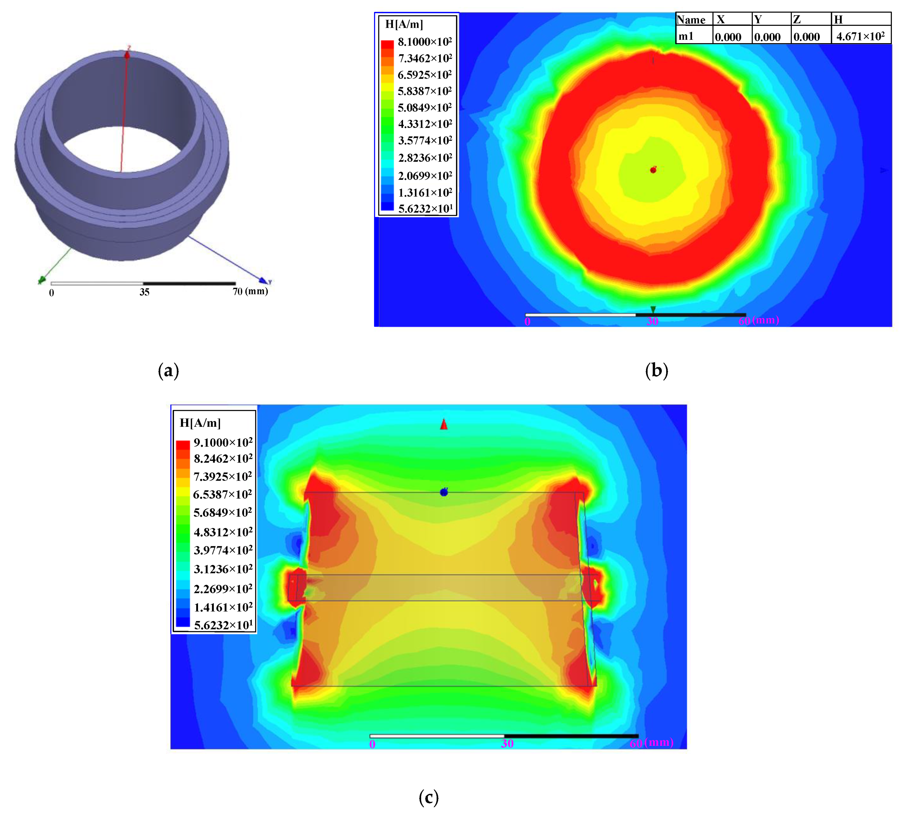
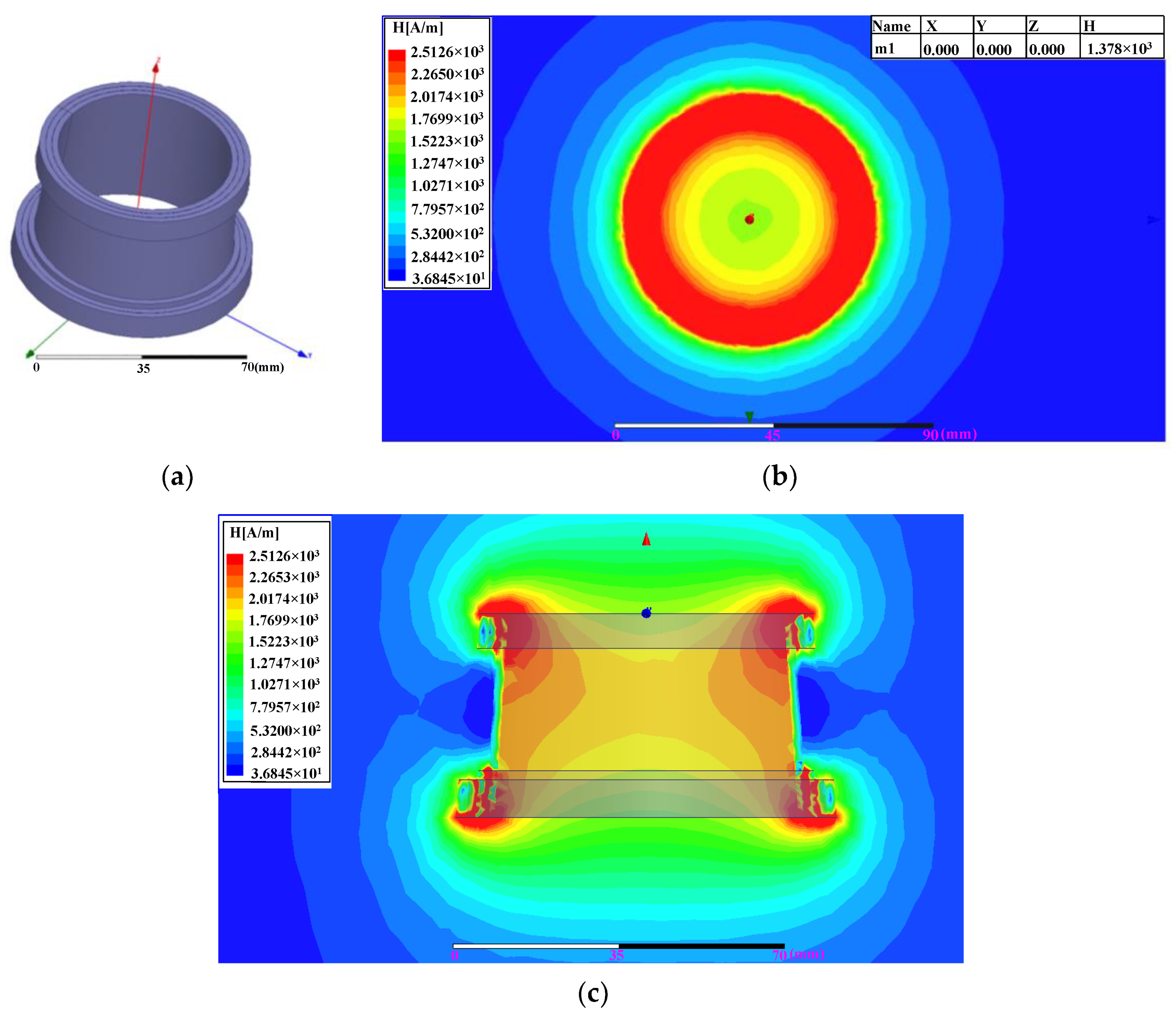
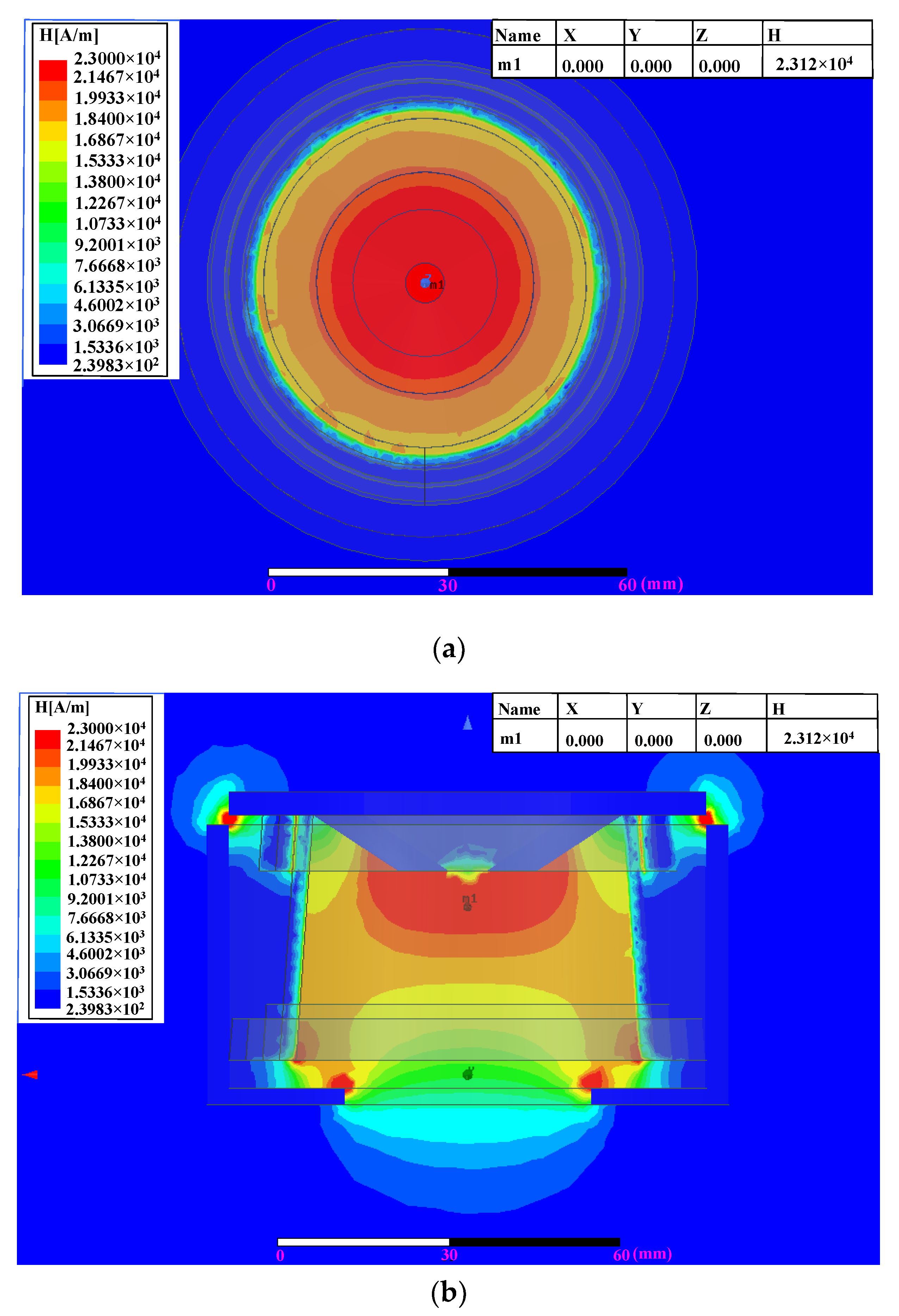
3.2. Electromagnetic Field Simulation

The efficiency, strength, and accuracy of electromagnetic induction heating are related to certain parameters, such as the size, shape, and spacing of the coil. Generally, the electromagnetic induction heating coil is made of one or several turns of copper tubes, based on the current of the system. The structural optimization and design of induction heating coil was carried out using ANSYS Maxwell simulation analysis [25,26]. For electromagnetic induction heating, the cutter is inserted into the top of the tool holder, and the coil is sleeved outside the tool holder. In order to improve heating efficiency and reduce heating loss, it is necessary to enhance the electromagnetic field strength of the coil, both around the surface of the tool holder and the top of the coil. It is possible to approximate the coils with equal lengths of copper blocks and to observe the electromagnetic field distribution of different winding structures, based on simulations using the ANSYS Maxwell software.
First, a classic coil structure was designed for testing and simulation, which was composed of four layers, each layer wound tightly in a circle and another circle. The load applied after modeling was a 30 A, 20 kHz current. The simulation results are shown in Figure 3. From Figure 3a, it can be seen that the electromagnetic field generated by the coil around the clamping part was the strongest and the simulated magnetic field strength (H) was about 3.841 × 10² A/m; however, there is obvious electromagnetic field leakage outside the coil. As the coil has a certain taper, the simulated distribution of the magnetic field was not uniform. It can be seen, from Figure 3b, that the electromagnetic field strength of the clamping part was relatively strong from top to bottom and, as a result, the heating effect of the clamping part from top to bottom is very fast and obvious [27].
Then, the classical structure was modified, with a layer of copper strands tightly wound around the bottom layer and a plurality of copper strands tightly wound in the middle of the 2–4 layers. The modified structure of the coil is shown in the Figure 4a. An alternating current at the same operating frequency and current intensity as in the first winding mode was used, and the electromagnetic field simulation results are shown in Figure 4b,c. Similar to the first structure, the electromagnetic field around the clamping part shown in Figure 4b was the strongest, but the electromagnetic field strength was increased to about 8.1000 × 10² A/m. The electromagnetic field leakage outside the coil was relatively obvious, as well. It can be seen, from Figure 4c, that the electromagnetic field strength of the clamping part was relatively strong at the top, middle, and bottom, where the heating effect of the clamping part was very fast and obvious. As a result, the temperature field of the clamping par was non-uniform from top to bottom.
It has been proved experimentally that the electromagnetic fields generated by the above two structures could not meet the strength requirements for the replacement of the cutter. Combined with the previous simulation results and analysis, the final determined coil structure is shown in Figure 5a, where the bottom layer was tightly wound one turn and one turn of copper wire, two layers were wound around the top of the coil by n turns of copper wire, and three layers were wound around the bottom of the coil by n+1 turns of copper wire. An alternating current at the same operating frequency and current intensity as in the first winding mode was used. The results are shown in Figure 5b,c. From Figure 5b, it can be seen that the electromagnetic field strength around the clamping part was the strongest, which was increased to 2.5126 × 10³ A/m and was much larger than the first and second cases; additionally, the distribution of the electromagnetic field was more regular and the electromagnetic field leakage was improved. The X–Z section of the magnetic field shown in Figure 5c was relatively strong at the top and bottom; as a result, the heating effect of the clamping part was very fast and obvious at the top and bottom. In order to further improve the heating effect and achieve the goal of replacing the cutter successfully, the surface and top electromagnetic field of the clamping part generated by the coil should be further enhanced [28]. The coil shown in Figure 5a was wrapped in a magnetic slot, as shown in Figure 6a, covered by a magnetic ring on the top of the coil, as shown in Figure 6b. The magnetic ring shown in Figure 6b was composed of a magnetic core at the bottom, an intermediate heat-radiating body, and a heat-insulating protective cover. The electromagnetic field simulation was performed again under the same conditions, and the simulated results are shown in Figure 7. Compared with Figure 5b, the magnetic field in the X–Y plane shown in Figure 7a was increased by one order of magnitude around the surface of the tool holder with the addition of the magnetic slot, and the magnetic leakage showed good improvement. It can be seen that the electromagnetic field strength in the middle of the coil, as shown in Figure 7b, was greatly increased, to 2.312 × 10⁴ A/m, by the addition of the magnetic ring covering the top of the coil, with which the inner wall of the clamping part achieved the fastest heating.
It has been shown that the electromagnetic field interacts with the temperature field in the process of induction heating, which is a bi-directional nonlinear coupling of the electromagnetic field and the temperature field [29,30]; the multi-field solver has been widely used to solve this problem in the ANSYS workbench. The calculation process of magneto-thermal coupling analysis is shown in the Figure 8. The molding structure of the induction heating established in the ANSYS workbench is shown in Figure 9a. First, the magnetic field solution type is set to eddy current, the structural model of the coil and the tool holder are established, the corresponding material parameters and the excitation parameters (such as heating time, current, and frequency) are added in the ANSYS Maxwell software, and the magnetic field simulation is performed. Secondly, the simulated magnetic field is sent to the transient thermal function of the ANSYS Workbench, the magnetic permeability, resistivity, and specific heat capacity (as a function of temperature) are introduced into the material manager of the ANSYS Workbench, and the tool holder is meshed and subjected to bi-directional magneto-thermal coupling analysis. The distribution of the three-dimensional temperature field based on the ANSYS workbench transient thermal analysis is shown in Figure 9b [31]. It can be seen, from Figure 9b, that the temperature distribution was consistent with the electromagnetic field distribution and the induction heating energy was concentrated at the top area of shrink-fit tool holder clamping part without diffusing to the bottom, which met the shrink-fit tool holder clamping part thermal expansion demands and verified the correctness of the coil design process. The highest temperature obtained by the simulation was about 370 °C, at the top of the clamping part.

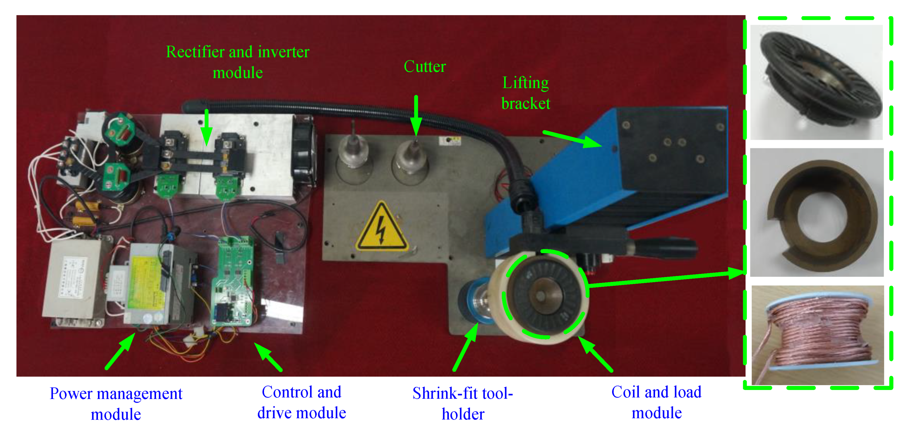
4. Design and Implementation of Tool Holder Heat-Loading Equipment

The overall framework of the tool holder heat-loading equipment is shown in Figure 10. A three-phase alternating current (AC) input is connected to a rectifier module to generate a 514 V direct current (DC) output. A phase AC input supply is reduced to 15 V by a step-down transformer and connected to the power management module, in order to generate an appropriate DC supply for each module of the control circuit and the STM32 microcontroller unit (MCU). The heating parameters of the tool holder can be adjusted through the buttons on the control module. Based on the set heating parameters, including tool holder diameter, heating time, and frequency, a pulse width modulation (PWM) wave is generated by the control module to drive the inverter circuit, composed of an insulated gate bipolar transistor (IGBT). The driving circuit drives the inverter circuit to generate a high-frequency AC current, which is connected to the induction heating coil. The STM32 advanced timer of TIM1 is used to generate the PWM wave [32]. As the equipment uses a full-bridge inverter structure and two IR2213 driver chips, four PWM waves are required for the drive signal. Ausbond-192AB type potting compound is poured into the gap between the electromagnetic field collecting groove and the coil, which enhances the heat dissipation ability of the coil. Furthermore, in order to protect against overheating, a bimetal thermostat connected to the microcontroller unit is buried in the coil. The overall heat shrinking machine is shown in Figure 11.
The material of the coil shown in Figure 11 is solderable polyurethane enameled round copper wire, the specification is 0.2 mm*100, the copper core cross-sectional area is 3.1416 mm2, and the resistivity is 5.772 Ω/km. The highest heat-resistant temperature is 155 °C and the highest withstand voltage is 1600 V. The measured impedance of the coil by the RLC (Resistance Inductance Capacitance) measuring instrument, as a function of frequency, is shown in Figure 12; the real part of the impedance is about 0.38 Ω, but the inductive reactance is proportional to frequency and is much larger than real part.
The software program of the equipment was composed of four modules, an initialization module, a key and display module, a PWM wave generation module, and an analog–digital (AD) sampling module. The flow chart of the program is shown in Figure 13.
The main point of the design and writing of the key-display modules is the logical relationship between the keys:
(1)
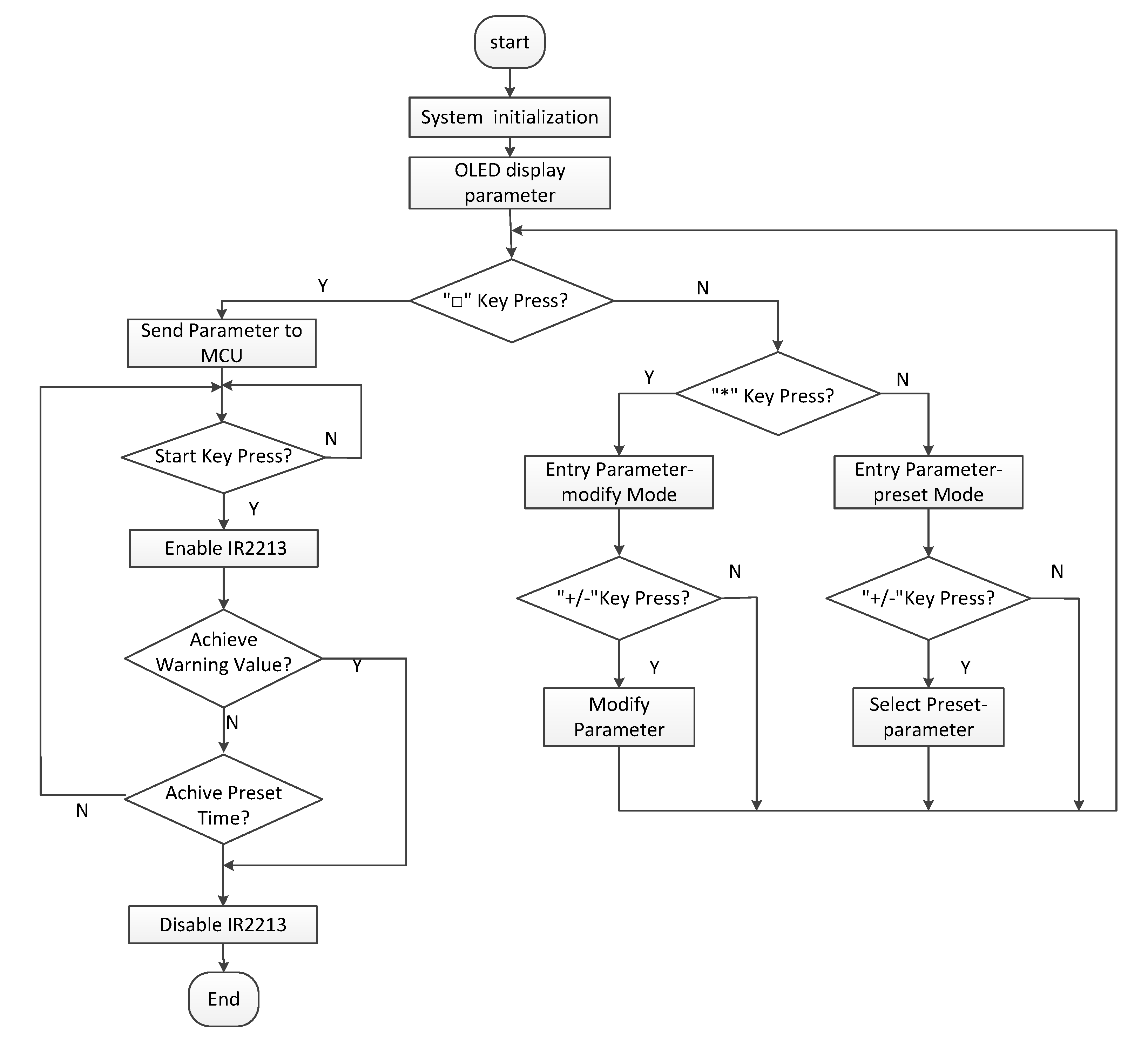
When the "Start" key is detected, the OLED (Organic Light-Emitting Diode) sends the parameter to the STM32 through the IIC (Inter-Integrated Circuit), thereby outputting a different PWM wave.
(2)
When the "*" key is first detected, the OLED enters the modified parameter mode. Then, the “*” button is pressed to modify the caliber parameter; the “*” button is pressed twice to modify the time parameter; the “*” button is pressed three times to modify the frequency parameter. When modifying the parameters, the path parameter modification step is 1.0 mm; the time parameter modification step is 0.2 s; and the frequency parameter modification step is 0.5 kHz. When the "*" key is pressed four times, the modified aperture parameter is returned.
(3)
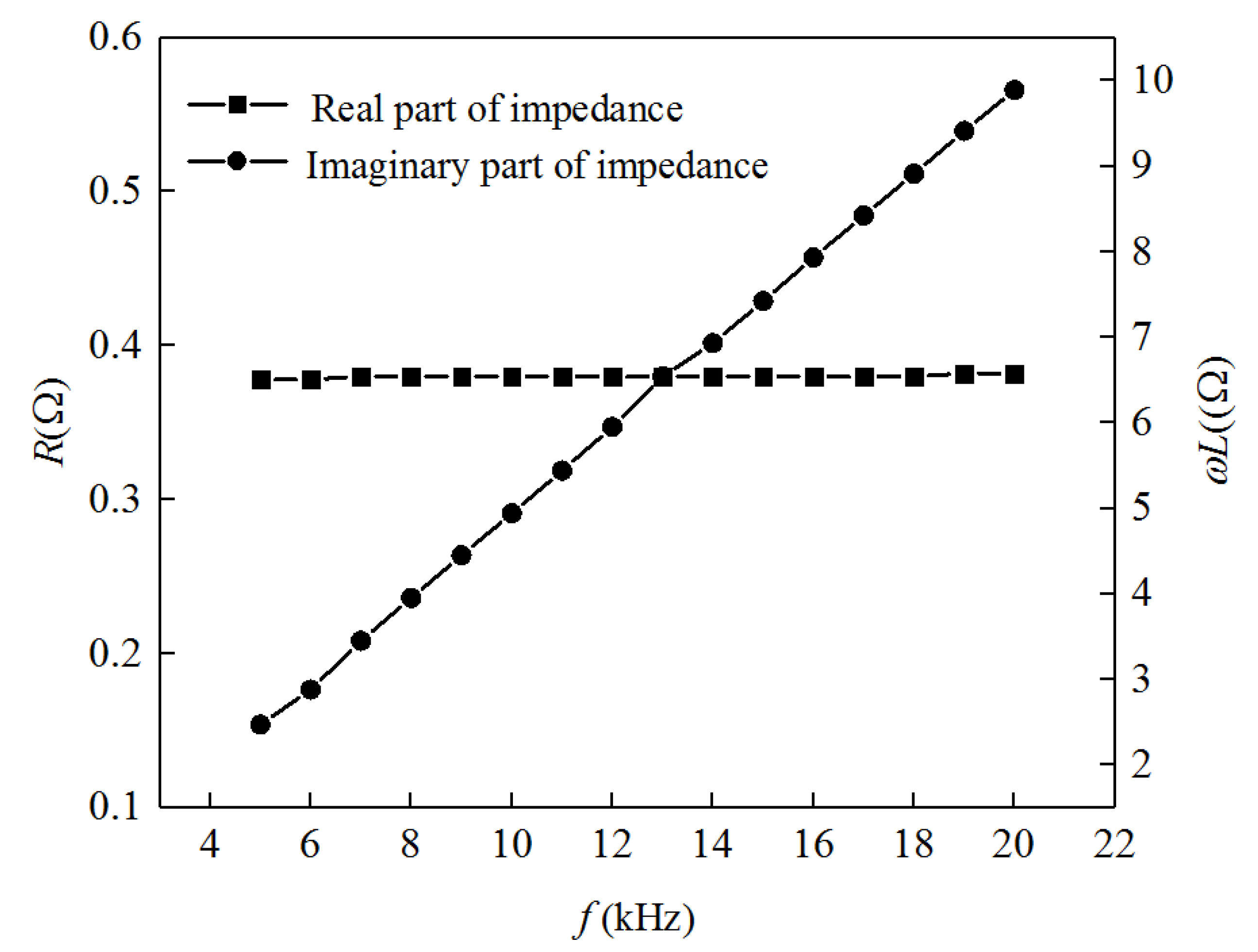
When the system does not detect the "*" key press, directly detecting the "+" key press, the parameter pre-existing in the OLED is made variable, with the caliber as the variable, and a parameter larger than the currently displayed caliber size is called, if direct detection is performed. When the "-" key is pressed, the parameter pre-existing in the OLED is made variable, and a parameter smaller than the currently displayed aperture size is called. At the same time, the frequency parameter is used as a limiting condition, where the frequency is limited to between 8–20 kHz.

5. Experiment and Analysis

A UT305A non-contact infrared thermometer was used to measure the temperature of the shrink-fit tool holder. The measured temperature range of the non-contact infrared thermometer is −50–1550 °C and the highest measurement accuracy is ±1.8 °C, which met the measurement requirements of the experiment. First, the heating time was fixed to 7.1 s. All experiments were repeated several times, one group of the measured temperatures (i.e., before and after heating) for each of the shrink-fit tool holders are listed in Table 2 and Table 3, respectively.
It can be seen that the heated temperatures of the BT40-SF06 were larger than those of the BT40-SF10, under the same heating conditions. The inserting and pulling out temperature was about 270 °C for BT40-SF06 but, for the BT40-SF10, the temperature was about 285 °C. When the heating time was set to 7.1 s, the insertion and removal of the tool could be completed, as long as the frequency was in the range of 12–20 kHz and the DC voltage was 245–255 V. When the DC voltage was substantially the same and the heating frequency was lowered, the heating effect was better; when the heating frequency was substantially constant and the DC voltage was increased, the heating effect was also better.
The DC voltage was set to 250 V and insertion and removal of the cutter was observed under different times and frequencies. The experiments were repeated several times, and one group of experimental results are shown in Table 4.
Finally, the optimal parameters of the two tool holders (at 250 V) were obtained, and those for the BT40-SF06 tool holder were found to be superior. The induction heating parameters for the BT40-SF06 are as follows: DC voltage 250 V, heating time 5 s, and heating frequency 16 kHz. For the BT40-SF10 tool holder, the induction heating parameters are as follows: DC voltage 250 V, heating time 6 s, and heating frequency 18 kHz.

6. Conclusions and Future Work

Based on the principle of electromagnetic induction heating technology and a high-speed machining tool system, hot-loading equipment to be used for a shrink-fit tool holder was designed and implemented in this paper. The designed equipment was based on the STM32F103RBT6 control circuit as the main chip, as well as an IGBT drive protection circuit based on the IR2213. The ANSYS Maxwell software was used to simulate coils with different winding modes to study the difference in electromagnetic field effect. The distribution of the coil structure was, finally, designed for the equipment. After the entire heat-installing equipment was built, the two handles of the BT40-SF06 and BT40-SF10 were used for experimental testing. In the heating experiment, the three parameters of voltage, heating time, and frequency were adjusted, and, finally, the optimal heating parameters of the whole equipment were determined. Through the experiment, the tool holder heating equipment was shown to be able to achieve the pre-determined functional target. The following conclusions have been drawn, based on the theoretical analysis and experimental results:
(1)
The magnetic field in the X–Y plane generated by the proposed coil was increased by one order of magnitude around the surface of the tool holder by the addition of the magnetic slot; furthermore, the magnetic leakage was improved. The electromagnetic field strength in the middle of the coil was greatly increased, to 2.312 × 10⁴ A/m, by the addition of a magnetic ring covering the top of the coil.
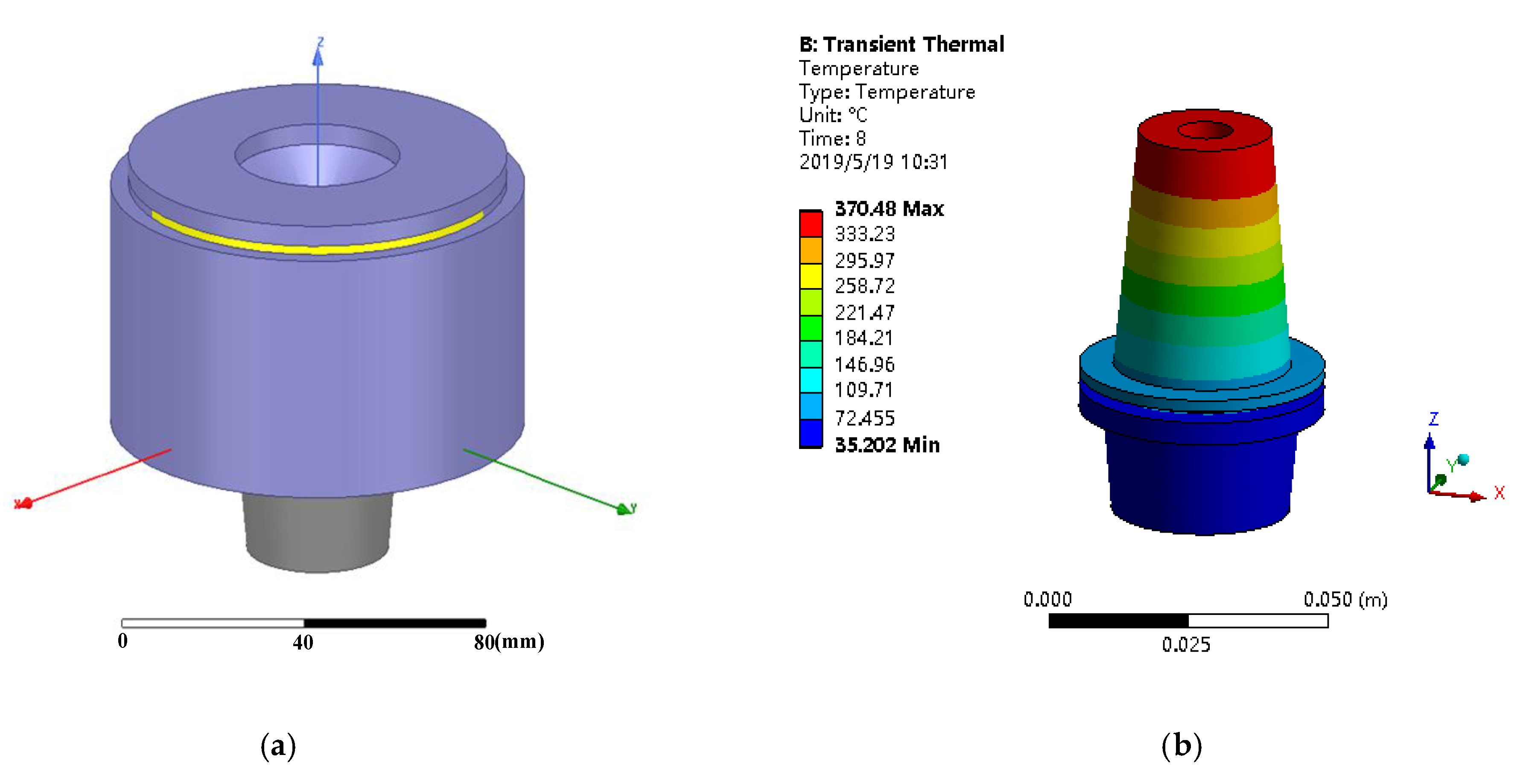
(2)
The simulated distribution of the three-dimensional temperature field was consistent with the electromagnetic field distribution. The highest temperature obtained by the simulation was about 370 °C, on the top of the clamping part, which was consistent with the measured result.
(3)
Under the same heating conditions, the heated temperatures of the BT40-SF06 were larger than those of the BT40-SF10. The inserting and pulling out temperature was about 270 °C for the BT40-SF06, but about 285 °C for the BT40-SF10, as determined experimentally. When the DC voltage was substantially the same and the heating frequency was lowered, or when the heating frequency was substantially constant and the DC voltage was increased, the heating effect was better.
In future work, the thermal fatigue problem of the tool holder during heating requires further study. A large number of repeated experiments and uncertainty analyses should be carried out to verify the reliability of the implemented heating equipment. The function of the heating coil in detecting the tool diameter is also to be further developed.

Author Contributions

X.W. proposed the idea and wrote the manuscript. C.L. and S.S. performed the experiments, R.T. processed the data. Q.L. guided the experiments and writing.

Funding

This research was funded by the College Students in Zhejiang Province Science and Technology Innovation Activity Plan (Planted Talent Plan) [2019R423001].

Acknowledgments

The research was supported by The National Key Research and Development Program of China (2017YFC0804604, 2017YFF0200550). The research was supported by the College Students in Zhejiang Province Science and Technology Innovation Activity Plan (Planted Talent Plan).

Conflicts of Interest

The authors declare no conflict of interest. The funders had no role in the design of the study; in the collection, analyses, or interpretation of data; in the writing of the manuscript, or in the decision to publish the results.

References

  1. Hanna, I.M.; Agapiou, J.S.; Stephenson, D.A. Modeling the HSK toolholder-spindle interface. J. Manuf. Sci. Eng. 2002, 124, 734–744. [Google Scholar] [CrossRef]
  2. Fleischer, J.; Schulze, V.; Klaiber, M.; Bauera, J.; Zangera, F.; Boeva, N.; Leberlea, U.; Spohrera, A.; Rothaupta, B. The influence of tool holder technologies on milling performance. Procedia CIRP 2016, 46, 226–229. [Google Scholar] [CrossRef]
  3. Namazi, M.; Altintas, Y.; Abe, T.; Rajapakse, N. Modeling and identification of tool holder-spindle interface dynamics. Int. J. Mach. Tools Manuf. 2007, 47, 1333–1341. [Google Scholar] [CrossRef]
  4. Iglesias, A.; Munoa, J.; Ciurana, J. Optimisation of face milling operations with structural chatter using a stability model based process planning methodology. Int. J. Adv. Manuf. Technol. 2014, 70, 559–571. [Google Scholar] [CrossRef]
  5. Karban, P.; Kotlan, V.; Dolezel, I. Numerical model of induction shrink fits in monolithic formulation. IEEE. Trans. Magn. 2012, 48, 315–318. [Google Scholar] [CrossRef]
  6. Yaser, M.; Milad, A.; Erhan, B. Suppressing vibration modes of spindle-holder-tool assembly through FRF modification for enhanced chatter stability. CIRP Ann. Manuf. Technol. 2018, 67, 397–400. [Google Scholar]
  7. Filiz, S.; Cheng, C.-H.; Powell, K.B.; Schmitz, T.L.; Ozdoganlar, O.B. An improved tool–holder model for RCSA tool-point frequency response prediction. Precis. Eng. 2009, 33, 26–36. [Google Scholar] [CrossRef]
  8. Lope, I.; Acero, J.; Carretero, C. Analysis and optimization of the efficiency of induction heating application with Litz-wire planar and solenoidal coils. IEEE Trans. Power Electron. 2016, 31, 5089–5101. [Google Scholar] [CrossRef]
  9. Chen, Y.L.; Cai, Y.; Shimizu, Y.; Ito, S.; Gao, W.; Ju, B.F. Ductile cutting of silicon microstructures with surface inclination measurement and compensation by using a force sensor integrated single point diamond tool. J. Micromech. Microeng. 2016, 26, 025002. [Google Scholar] [CrossRef]
  10. Yang, R.Z.; He, Y.Z.; Zhang, H.; Huang, S.D. Through coating imaging and nondestructive visualization evaluation of early marine corrosion using electromagnetic induction thermography. Ocean Eng. 2018, 147, 277–288. [Google Scholar] [CrossRef]
  11. Chen, S.P.; Li, L. The hot-mounted tool holder for high-speed Precision Machining. Manuf. Technol. Mach. Tool 2008, 139–141. [Google Scholar]
  12. Cheng, Q.; Liu, X.Y.; Zhao, Y.S.; An, G.P. Identification of dynamical contact parameters for spindle-tool holder interface based on frequency response functions. J. Univ. Sci. Technol. B 2013, 39, 1144–1148. [Google Scholar]
  13. Carvalho, S.R.; Silva, S.M.M.L.E.; Machado, A.R.; Guimarãesa, G. Temperature determination at the chip–tool interface using an inverse thermal model considering the tool and tool holder. J. Mater. Process Technol. 2006, 179, 97–104. [Google Scholar] [CrossRef]
  14. Schmitz, T.L.; Powell, K.; Won, D.; Ziegert, J.C. Shrink fit tool holder connection stiffness/damping modeling for frequency response prediction in milling. Int. J. Mach. Tool Manuf. 2007, 47, 1368–1380. [Google Scholar] [CrossRef]
  15. Zhou, H.; Wang, C.; Tang, D.; Peng, R. Dynamic analysis of the lengthened shrink-fit holder and cutting tool system in high-speed milling. Mach. Sci. Technol. 2012, 16, 157–172. [Google Scholar] [CrossRef]
  16. Chen, J.; Tian, L.; Shang, H.M.; Wang, G.C. Thermal fatigue analysis of HSK shrink toolholder. Appl. Mech. Mater. 2014, 532, 408–412. [Google Scholar] [CrossRef]
  17. Rezaei, M.M.; Movahhedy, M.R.; Moradi, H.; Ahmadian, M.T. Extending the inverse receptance coupling method for prediction of tool holder joint dynamics in milling. J. Manuf. Process. 2012, 14, 199–207. [Google Scholar] [CrossRef]
  18. Liao, J.; Zhang, J.; Feng, P.; Yu, D.; Wu, Z. Identification of contact stiffness of shrink-fit tool-holder joint based on fractal theory. Int. J. Adv. Manuf. Technol. 2017, 90, 2173–2184. [Google Scholar] [CrossRef]
  19. Yamazaki, K.; Yu, F. Effect of eddy-current loss reduction by magnet segmentation in synchronous motors with concentrated windings. IEEE. Trans. Ind. Appl. 2011, 47, 779–788. [Google Scholar] [CrossRef]
  20. Fu, X.B.; Wang, B.Y.; Tang, X.F.; Ji, H.C.; Zhu, X.X. Study on induction heating of workpiece before gear rolling process with different coilstructures. Appl. Therm. Eng. 2017, 114, 1–9. [Google Scholar] [CrossRef]
  21. Boglietti, A.; Cavagnino, A.; Lazzari, M. Computational algorithms for induction motor equivalent circuit parameter determination—Part II: Skin Effect and Magnetizing Characteristics. IEEE Trans. Ind. Electron. 2011, 58, 3734–3740. [Google Scholar] [CrossRef]
  22. Yamazaki, K.; Abe, A. Loss investigation of interior permanent-magnet motors considering carrier harmonics and magnet eddy currents. IEEE Trans. Ind. Appl. 2009, 45, 659–665. [Google Scholar] [CrossRef]
  23. Ebrahimi, B.; Khamesee, M.B.; Golnaraghi, M.F. Design and modeling of a magnetic shock absorber based on eddy current damping effect. J. Sound Vib. 2008, 315, 875–889. [Google Scholar] [CrossRef]
  24. Carr, W.J.J. Ac loss in a twisted filamentary superconducting wire. II. J. Appl. Phys. 1974, 45, 929–934. [Google Scholar] [CrossRef]
  25. Di Barba, P.; Forzan, M.; Sieni, E. Multiobjective design optimization of an induction heating device: A benchmark problem. Int. J. Appl. Electrom. 2015, 47, 1003–1013. [Google Scholar] [CrossRef]
  26. Lei, G.; Zhu, J.G.; Guo, Y.G.; Liu, C.C.; Ma, B.A. Review of design optimization methods for electrical machines. Energies 2017, 10, 1962. [Google Scholar] [CrossRef]
  27. Hatic, V.; Mavric, B.; Kosnik, N.; Sarler, B. Simulation of direct chill casting under the influence of a low-frequency electromagnetic field. Appl. Math. Model. 2018, 54, 170–188. [Google Scholar] [CrossRef]
  28. Li, Y.B.; Yan, H.B.; Massoudi, M.; Wu, W.T. Effects of anisotropic thermal conductivity and Lorentz force on the flow and heat transfer of a Ferro-Nanofluid in a magnetic field. Energies 2017, 10, 1065. [Google Scholar] [CrossRef]
  29. Sergeant, P.; Hectors, D.; Dupre, L.; Reusel, K.V. Thermal analysis of magnetic shields for induction heating. IET Electron. Power. Appl. 2009, 3, 543–550. [Google Scholar] [CrossRef] [Green Version]
  30. Arslan, M.A. Coupled thermal/structural contact analyses of shrink-fit tool holder. Proc. Inst. Mech. Eng. Part B J. Eng. Manuf. 2014, 228, 715–724. [Google Scholar] [CrossRef]
  31. Malekzadeh, P.; Golbahar Haghighi, M.R.; Heydarpour, Y. Heat transfer analysis of functionally graded hollow cylinders subjected to an axisymmetric moving boundary heat flux. Numer. Heat Transf. Part A Appl. 2012, 61, 614–632. [Google Scholar] [CrossRef]
  32. Ahmadi, D.; Wang, J. Online selective harmonic compensation and power generation with distributed energy resources. IEEE Trans. Power. Electron. 2014, 29, 3738–3747. [Google Scholar] [CrossRef]
Figure 1. Induction heating diagram and section of the coil structure: (a) illustration of the induction heating principle; and (b) cross-section of the coil structure.
Energies 12 03416 g001
Figure 2. BT40-SF shrink-fit tool holder (a) physical photo; (b) structure diagram.
Energies 12 03416 g002
Figure 3. Simulated electromagnetic field of a four-layer tightly wound coil: (a) X–Y section of the electromagnetic field; and (b) X–Z section of the magnetic field.
Energies 12 03416 g003
Figure 4. The two–four layer intermediate winding coil and simulated electromagnetic field: (a) structural diagram; (b) X–Y section of the magnetic field; and (c) X–Z section of the magnetic field.
Energies 12 03416 g004
Figure 5. The structure of the coil and simulated electromagnetic field: (a) structural diagram; (b) X–Y section of the electromagnetic field; and (c) X–Z section of the magnetic field.
Energies 12 03416 g005
Figure 6. Structure of magnetic slot and magnetic ring: (a) magnetic slot; (b) bottom view of the magnetic ring; and (c) top view of the magnetic ring.
Energies 12 03416 g006
Figure 7. The simulated electromagnetic field of the final coil: (a) X–Y section of the magnetic field; and (b) X–Z section of the magnetic field.
Energies 12 03416 g007
Figure 8. Flow chart of the coupled electro-magnetic-thermal simulation procedure.
Energies 12 03416 g008
Figure 9. Simulated model and temperature field of shrink-fit holder (a) simulated model; (b) simulated temperature field.
Energies 12 03416 g009
Figure 10. Overall circuit framework of tool holder heat-loading equipment.
Energies 12 03416 g010
Figure 11. Tool holder heat-loading equipment.
Energies 12 03416 g011
Figure 12. Impedance of coil as a function of frequency.
Energies 12 03416 g012
Figure 13. Program flow chart.
Energies 12 03416 g013
Table 1. The parameters of the shrink-fit tool holder.
ModelTaperNo.dm (mm)D1 (mm)D2 (mm)L (mm)H (mm)ScrewMaterial
BT40-SF×06-9040620279036SO06014C4Cr5MoSiV1
BT40-SF×10-90401024329042SO06014C4Cr5MoSiV1
Table 2. Experimental results of the BT40-SF06 tool holder.
DC Voltage (V)Starting Temperature (°C)Heating Frequency (kHz)Heating Temperature (°C)
202.424.920 208.9
205.528.018221.4
207.327.416 228.8
205.126.014237.7
201.725.012252.1
223.723.020254.7
225.224.718269.9
228.325.616280.7
225.026.114294.4
224.425.112316.1
256.425.320318.4
264.125.218342.5
248.726.816356.9
249.924.414370.1
251.824.812387.3
Table 3. Experimental results of BT40-SF10 tool holder.
DC Voltage (V)Starting Temperature (°C)Heating Frequency (kHz)Final Temperature (°C)
205.527.618 211.4
207.327.416219.3
205.125.714226.6
203.625.512239.9
223.723.220248.8
225.224.218259.1
228.325.016270.0
225.025.914284.9
256.425.120304.9
264.125.318333.5
248.726.516347.0
249.924.914359.7
250.125.512370.1
Table 4. Experimental results of BT40-SF06/ BT40-SF10 under DC 250V.
Starting Temperature (°C)Heating Frequency (kHz)Heating Time (s)Heating Temperature (°C) BT40-SF06Heating Temperature (°C) BT40-SF10
23.3205251.1245.1
26.3206286.3276.3
26.4207318.4304.9
24.1208341.8332.2
25.5185287.2281.3
25.2186313.8307.2
24.218 7334.1333.5
24.3188365.4363.7
23.9165307.7298.6
24.016 6331.6330.4
25.1167350.9347.0
24.7168378.2375.4
25.6145311.2304.7
25.0146342.3330.3
25.5147370.1359.7
24.8148 398.5385.1
24.6125341.7322.3
26.1126370.0351.5
24.7127389.3370.1
24.9128412.1397.2

