Article

Design for the Interior Permanent Magnet Synchronous Motor Drive System Based on the Z-Source Inverter

School of Electrical Engineering & Automation, Harbin Institute of Technology, Harbin 150000, China
*
Author to whom correspondence should be addressed.
Energies 2019, 12(17), 3350; https://doi.org/10.3390/en12173350
Submission received: 13 August 2019 / Revised: 20 August 2019 / Accepted: 28 August 2019 / Published: 30 August 2019

Abstract

:
The permanent magnet synchronous motor (PMSM) running above the base speed requires flux-weakening control, which is usually realized by the direct-axis demagnetization current generated by the vector control, thus leading to a decrease in the system efficiency in the flux-weakening region. In addition, the motor power output range is limited by the inverter output voltage and current level. In this paper, a Z-Source drive PMSM control system with adjustable DC-link voltage was proposed to improve the efficiency of the motor system. The proposed system was experimentally verified. The response time of DC-link voltage is 10 ms and the overshoot is 3%, indicating good dynamic characteristics. Compared with the flux-weakening scheme, the Z-Source inverter scheme can achieve higher efficiency (about 3%) when the PMSM speed was set to 650 r/min.

1. Introduction

The motor and its control system are the key core components of electric vehicles [1]. The permanent magnet synchronous motor (PMSM) drive system has high efficiency and high-power density, so it has become the preferred drive system in all types of electric vehicles. For example, in the hybrid car Prius, which has the largest share in the global market at present, both the main drive motor and starting generator adopt the PMSM system. To improve the system performance, intelligent algorithms were adopted in the control strategies [2,3,4]. In the motor drive system powered by storage battery or super-capacitors used in electric vehicles, two schemes are generally adopted to increase the motor speed: flux-weakening control and increasing the DC-link voltage. Compared with the surface PMSM, the interior PMSM is more suitable for the flux-weakening speed-rising due to the reluctance torque produced by the inconsistent rotor inductance between the direct axis and quadrature axis [5,6].
The Z-Source inverter is a power converter topology proposed in 2003 by Peng Fangzheng of Michigan State University [7]. The inverter can adjust the DC-link voltage and allow the shoot-through state [8,9,10]. The Z-Source network consists of two pairs of symmetrical inductors, capacitors, and an input diode. The charging and discharging control of the inductor and capacitor is completed by switching the three-phase bridge arm between the shoot-through state and the non-shoot-through state so that the DC-link voltage can be boosted in the non-shoot-through state of the inverter bridge to achieve the purpose of voltage rise, as shown in Figure 1.
In this paper, a DC-link voltage-adjustable PMSM control system based on bidirectional voltage-fed Z-Source was proposed and applied in the interior PMSM drive system.
In the non-shoot-through state, the input diode conducts and the inductor voltage vL and DC-link voltage Vdc satisfy the following expressions:
v L = V i n V C
V d c = v L + V C
where Vin is the DC input voltage and VC is the capacitor voltage.
By Equations (1) and (2), we can get the following:
v L = 2 V C V i n
In the shoot-through state, the input diode is forced to turn off and the inductor voltage is equal to the capacitor voltage:
v L = V C
Suppose that the shoot-through ratio is ds and the switching cycle is Ts, we can get the following equation by means of the “voltage-second” balance principle:
( 2 V C V i n ) × ( 1 d s ) × T s + V C × d s × T s = 0
Finally, the DC-link voltage is expressed as follows:
V d c = 1 1 2 d s V i n
To increase the working region of torque and speed of PMSM, both flux-weakening and DC/DC voltage boosting schemes can also be adopted.
However, the flux-weakening control is realized by the direct-axis demagnetization current generated by the vector control. The demagnetization current leads to the increase in the inverter capacity and the decrease in the system efficiency in the working area of demagnetization. In order to improve the constant power speed range (CPSR) of a motor system, a compromised scheme is usually adopted in the motor design, thus increasing the volume and weight of the motor [11,12].
Adding a bidirectional DC/DC converter between the DC power source and the inverter can effectively increase the DC-link voltage [13]. However, in order to avoid the shoot-through state, dead time is generally added in the drive output. The presence of dead time increases the torque ripple and harmonic loss of the motor. In order to reduce the adverse effect caused by dead time, it is often necessary to add dead time compensation, which increases the control difficulty [14,15].
Compared to the above schemes, the proposed Z-Source converters adopt less active devices and have the higher reliability [16,17,18]. Based on the reasonable design, the system has good dynamic characteristics, which will be shown in the experimental results.

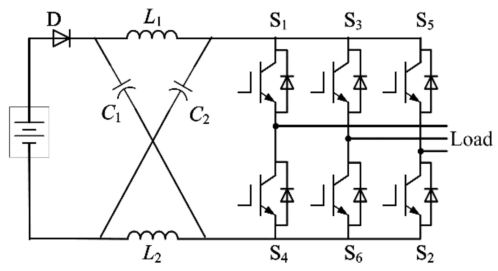
2. Power Circuit Parameter Design

The parameters of the PMSM are shown in Table 1.

2.1. Inductor Design

The average value of the inductor current can be expressed as follows:
I L = P o V i n
where Po is the output power.
According to References [19,20], the maximum inductor current ripple generated by the SVM4 strategy is smaller than that of SVM6, which is beneficial to reduce the inductor volume. Therefore, the SVM4 strategy is adopted. At this time, the inductor current ripple is as follows:
Δ i L = m d s V i n 2 L f s ( 1 2 d s )
where m is the modulation index; L is the inductance of the inductor; and fs is the switching frequency.
i L max = I L + 1 2 Δ i L

2.2. Capacitor Selection

The average value of the capacitor voltage meets:
V C = 1 d s 1 2 d s V i n
At this time, the capacitor voltage ripple is as follows:
Δ v C = I L 2 C f s ( 1 + 2 d s + m )
The maximum capacitor voltage is as follows:
v C = V C + 1 2 Δ v C

2.3. Power Circuit Devices Selection

When single-phase shoot-through occurs, the peak current stress of the switching device is as follows:
i max = 2 i L = 2 ( I L + 1 2 Δ i L ) + i p h
The maximum voltage stress is equal to the DC-link voltage:
v max = 1 1 2 d s V i n
The designed Z-Source converter parameters are shown in Table 2.

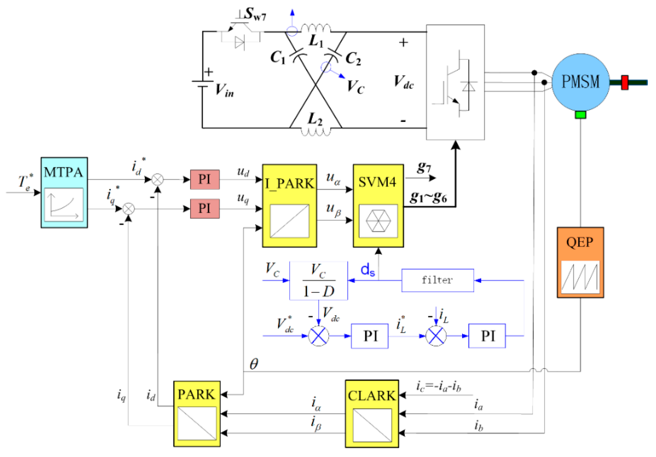
3. Control System Design

3.1. DC Side Voltage Closed Loop Design

The Z-Source inverter closed-loop control system can be divided into voltage feedback mode and current feedback mode. The voltage feedback mode is a DC-link voltage single loop control and the current feedback mode is a double-loop control, where the outer loop is a DC-link voltage loop and the inner loop is an inductor current loop. The feedback voltage in the voltage loop closely follows the given voltage in the voltage mode or current mode. The current mode has another current inner loop, which can effectively adjust the inductor current, improve the speed response characteristics, and detect the influence of load change on the DC-link voltage in advance. The control strategy in the Z-Source network is described as follows. With the inductor L1 current as the inner loop and the capacitor C1 voltage as the outer loop, the control of the DC-link voltage is realized by controlling the capacitor voltage, as shown in Figure 2. As the inner loop, the inductor current can not only restrain the current overshoot but also improve the dynamic response of the system. The DC-link voltage is expressed as follows:
V d c * = ω 3 ( L d i d + ψ f )   2 + ( L q i q )   2
where V d c * is the given DC-link voltage, ω is the motor angular velocity, Ld is the direct axis inductance, Lq is the quadrature axis inductance, and ψ f is the magnet flux. In the actual control process, on the basis of Equation (15), 1.2 times of the margin was selected.

3.2. AC Side Controller Design

The motor side adopted the maximum torque per ampere control (MTPA) [21,22,23]. The motor current was obtained by two Hall current sensors. For the control, the cutoff frequency of the DC-link voltage loop was set to be lower than that of the motor current loop.

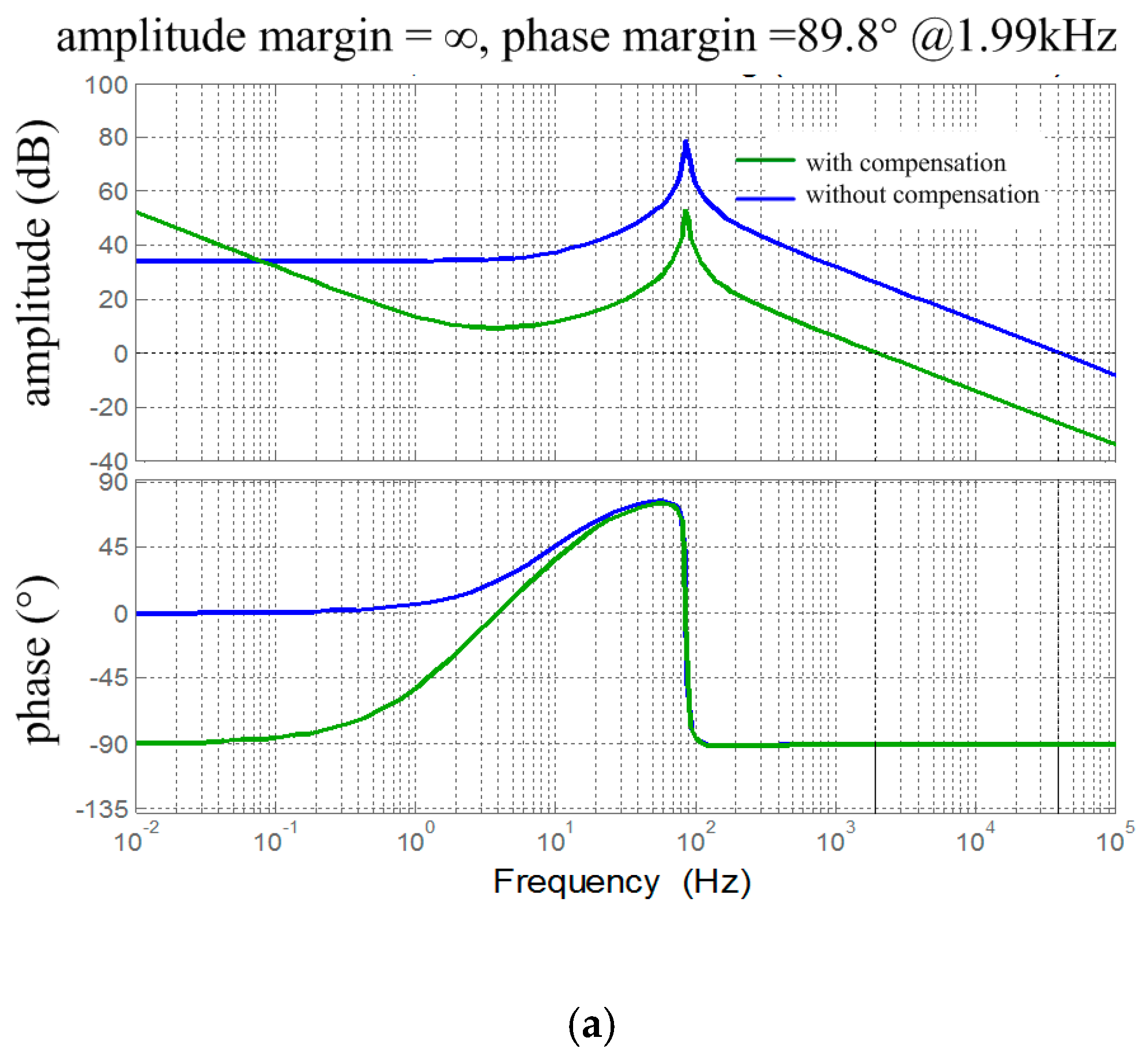
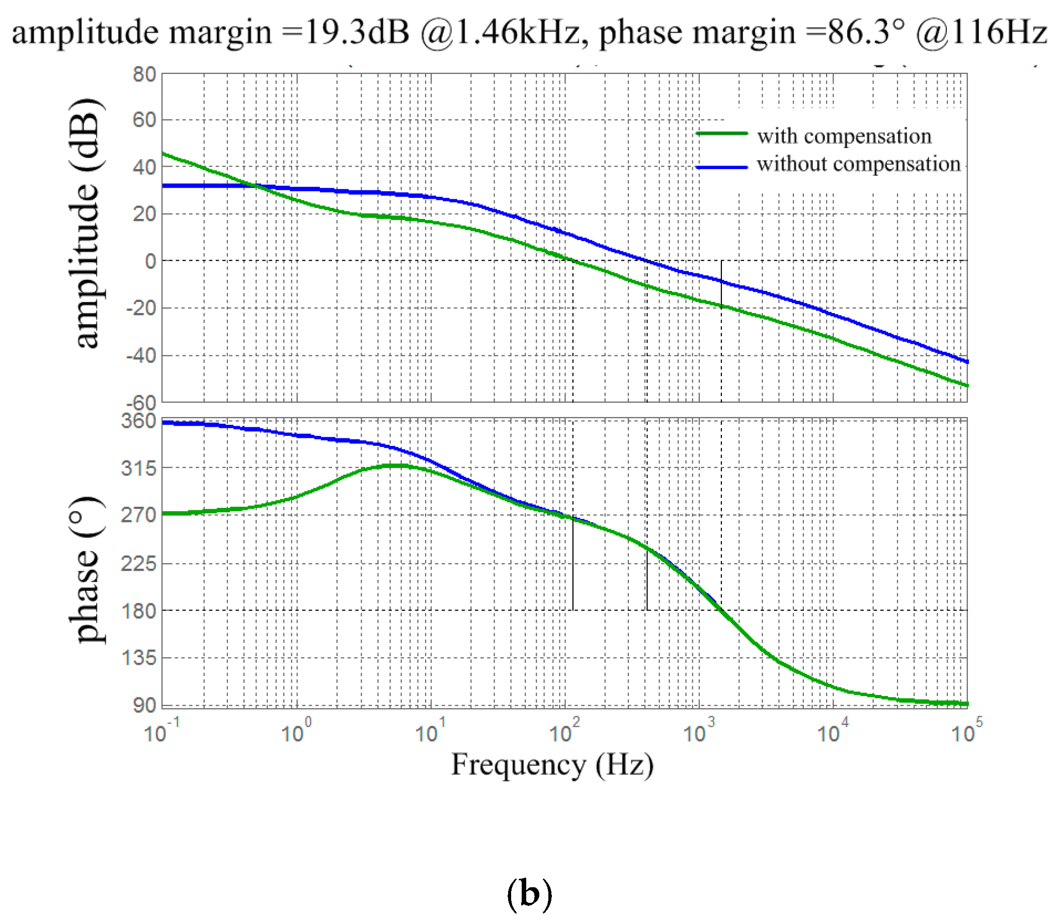
3.3. Compensation Network Design

The open-loop transfer functions of the inductor current and the DC-link voltage of the inverter with respect to the shoot-through ratio is as follows [24,25]:
G i d ( s ) = i ^ L ( s ) d ^ s ( s ) = 1 1 2 d s V i n C s + I l o a d L C s 2 + C r s + ( 1 2 d s ) 2
G v d ( s ) = v ^ d c ( s ) d ^ s ( s ) = 4 1 d s 1 2 d s I l o a d L s + 2 V i n 4 1 d s 1 2 d s I l o a d   r L C s 2 + C r s + ( 1 2 d s ) 2
where Gid(s) is the open-loop transfer function of the inductor current to the shoot-through ratio; Gvd(s) is the open-loop transfer function of the DC-link voltage to the shoot-through ratio; i ^ L , v ^ d c , and d ^ s are the disturbance of inductor current, DC-link voltage, and shoot-through ratio, respectively; C is the capacitance of the capacitor; L is the inductance of the inductor; r is the equivalent series resistance of inductor and measured to be 35 mΩ; and Iload is the effective value of load current.
The thin-film capacitor was used in the experimental platform, and its equivalent series resistance was small, so it was ignored in the modelling process. In the double-loop control, inductor current loop and DC-link voltage loop were compensated with series PI. After the inductor current loop was compensated, its closed loop transfer function was considered as a part of the voltage loop for additional compensation. The open loop amplitude–frequency characteristic curves of the current and voltage of the system before and after compensation are shown in Figure 3.
In the low-frequency range of the amplitude–frequency characteristic curves, both the slopes of current and voltage curves gradually increased after compensation (Figure 3), indicating that the compensation could reduce the steady-state error of the system and improve the accuracy. As the inner loop, the current loop should have the characteristics of quick response and its bandwidth should be about 10 times of that of the outer loop. In addition, in order to suppress high-frequency noise, the cutoff frequency of the amplitude–frequency characteristic curve of the inductive current was modified as 1/5 of the switching frequency, 1.99 kHz, and the phase margin was set to be 89.8 deg. The small overshoot and short response time was realized. The dynamic response was good. The DC-link peak voltage is DC voltage, and its stability and error characteristics are the focus in the control. Therefore, its cutoff frequency was set as 116 Hz and the phase margin was set as 86.3 deg, thus realizing small overshoot and short response time.

4. Loss Analysis

4.1. ZSI Converter Loss

Single IGBT conduction loss of the inverter bridge can be expressed as follows:
P c , T = u C E 0 [ i ^ N 2 π ( 1 d s + π 4 m cos φ ) + 2 I L 3 d s ] + r C E [ i ^ N 2 12 π ( 3 π 2 3 4 m + 6 m cos φ 3 m   cos 2 φ ) + 4 I L 2 9 d s ]
where uCE0 is the ideal conduction pressure drop of IGBT; rCE is equivalent resistance of IGBT; i ^ N is the peak value of the load current; IL is the average value of the inductor current; and cosφ is the load power factor.
The IGBT switching loss is expressed as follows:
P s , T = f s ( E o n + E o f f ) ( 1 π v ^ d c v r e f i ^ N i r e f + 2 3 v ^ d c v r e f I L i r e f )
where vref and iref are respectively IGBT reference working voltage and current and Eon and Eoff are respectively the turn-on and turn-off losses of IGBT at the reference working point.
The conduction loss of freewheel diode is expressed as follows:
P c , D = u F 0 i ^ N 2 π ( 1 d s π 4 m cos φ ) + r F 0 [ i ^ N 2 12 π ( 3 π 2 + 3 4 3 m 6 m cos φ + 3 m   cos 2 φ ) + 1 8 ( 1 d s ) ]
where uF0 is the ideal conduction voltage drop of diode and rF0 is the diode equivalent resistance.
The reverse recovery loss of freewheel diode is expressed as follows:
P s , D = 1 π f s E r e c v ^ d c v r e f i ^ N i r e f
where Erec is the diode reverse recovery loss at the reference working point.
The conduction loss of input diode can be expressed as follows:
P c , D 7 = u F 0 I L 1 d s + r F 0 ( I L 1 d s ) 2
The reverse recovery loss of input diode is expressed as follows:
P s , D 7 = 2 f s E r e c v c v i n v r e f 2 I L i r e f

4.2. Motor Loss

When PMSM is in the non-extremely high-speed state, the loss of permanent magnet rotor can be ignored. As for the stator winding loss, only copper loss and iron loss of stator winding are considered because mechanical loss and stray loss are uncontrollable and account for a small proportion.
The copper loss on stator winding resistance caused by motor current is expressed as follows:
p c u = 3 2 R s ( i d 2 + i q 2 )
where Rs is the stator winding resistance and id and iq are the d and q axis currents, respectively.
According to the generation mechanism of iron loss, iron loss can be divided into hysteresis loss and eddy current loss. When silicon steel sheets with common properties are used, the hysteresis loss generated under the speed below the base speed is far greater than the eddy current loss, so the eddy current loss can be ignored. The total iron loss is approximately equal to the hysteresis loss. According to Steinmetz formula, the iron loss of PMSM is expressed as follows:
P f e = k h B β p ω   m s t
where kh is the hysteresis loss coefficient; B is the magnetic flux density; β is Steinmetz constant and generally in the range of 1.8–2.0; and mst is the mass of stator core.
From the point of view of the controller, the voltage boosting scheme of the Z-Source inverter led to additional diode loss on the input side and increased the voltage stress of the inverter bridge switches. However, the current stress of the switch was higher when the traditional voltage source inverter adopted the flux-weakening scheme. Therefore, the losses of the two controllers were different. From the motor’s point of view, the voltage boosting scheme did not produce additional demagnetization current, so the copper loss was smaller. After the flux-weakening control scheme was adopted, the fundamental flux density decreased but the iron loss remained unchanged. The unchanged iron loss might be interpreted as follows. After the flux-weakening control scheme was adopted, the harmonic iron loss caused by armature reaction increased sharply, so the overall iron loss did not show significant change. Compared with the flux-weakening scheme, the voltage boosting scheme could improve the motor efficiency more significantly. In recent years, some scholars also reported that the efficiency of the PMSM scheme driven by boost circuit plus PWM inverter was higher than that of the flux-weakening scheme [26,27]. Z-Source inverter can increase the DC-link voltage and turn all the winding current into torque current. Therefore, the voltage-boosting scheme can achieve higher efficiency than the traditional flux-weakening scheme.

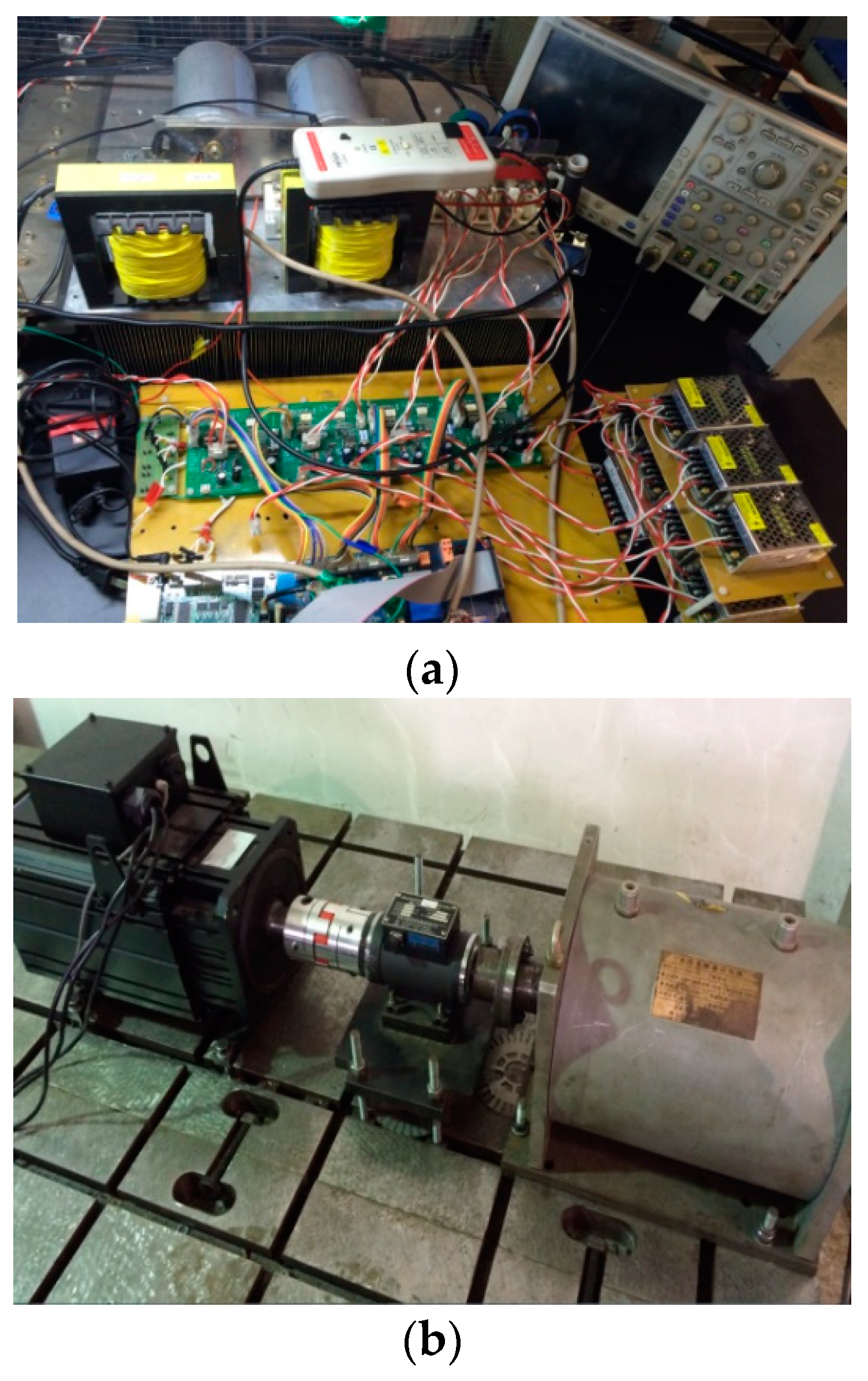
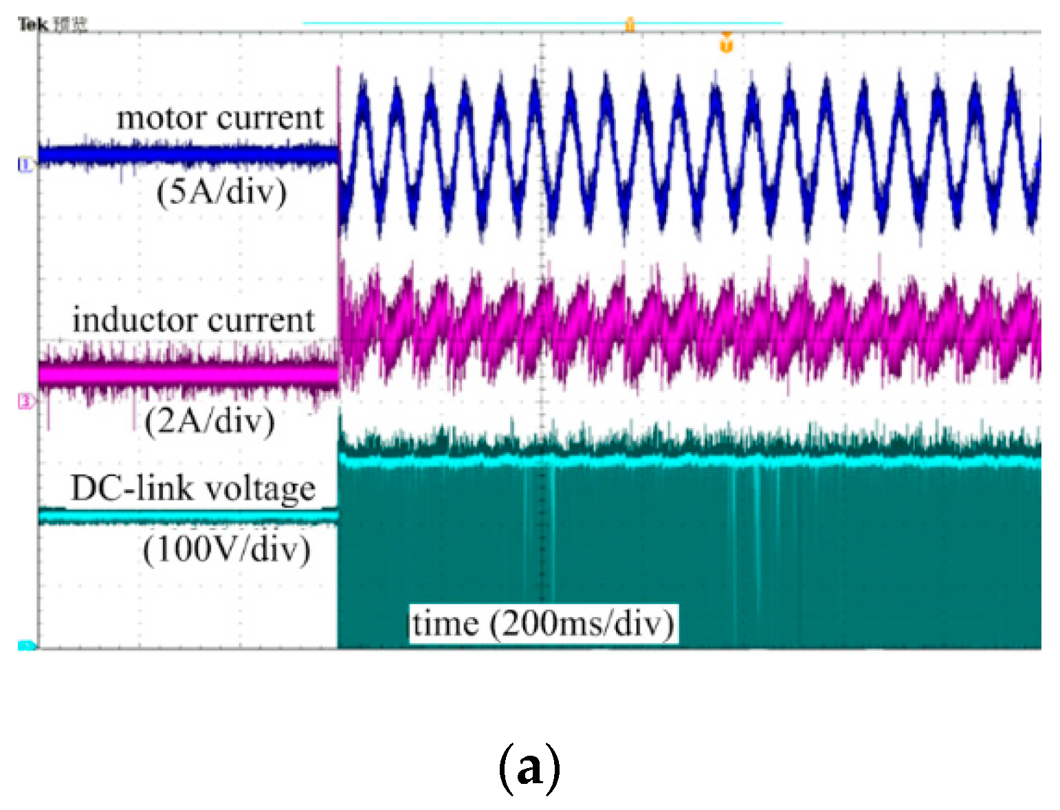
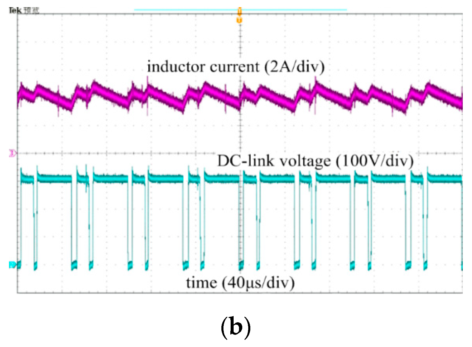
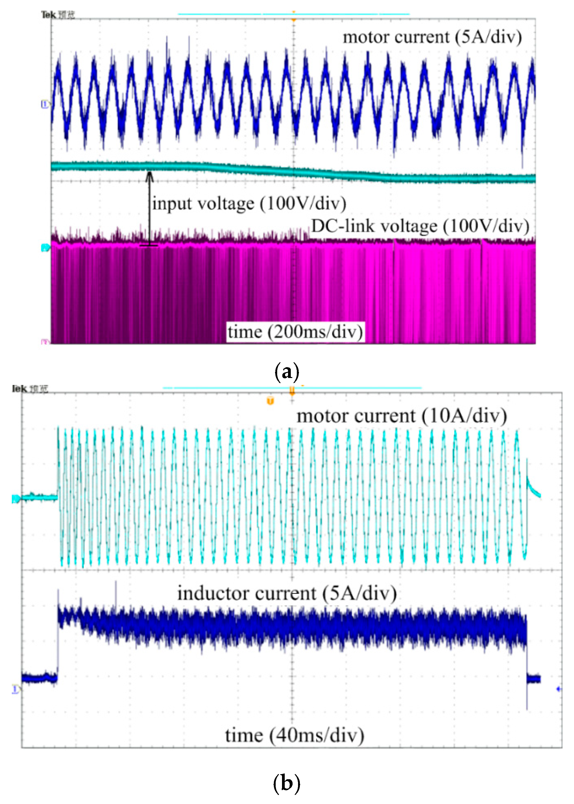
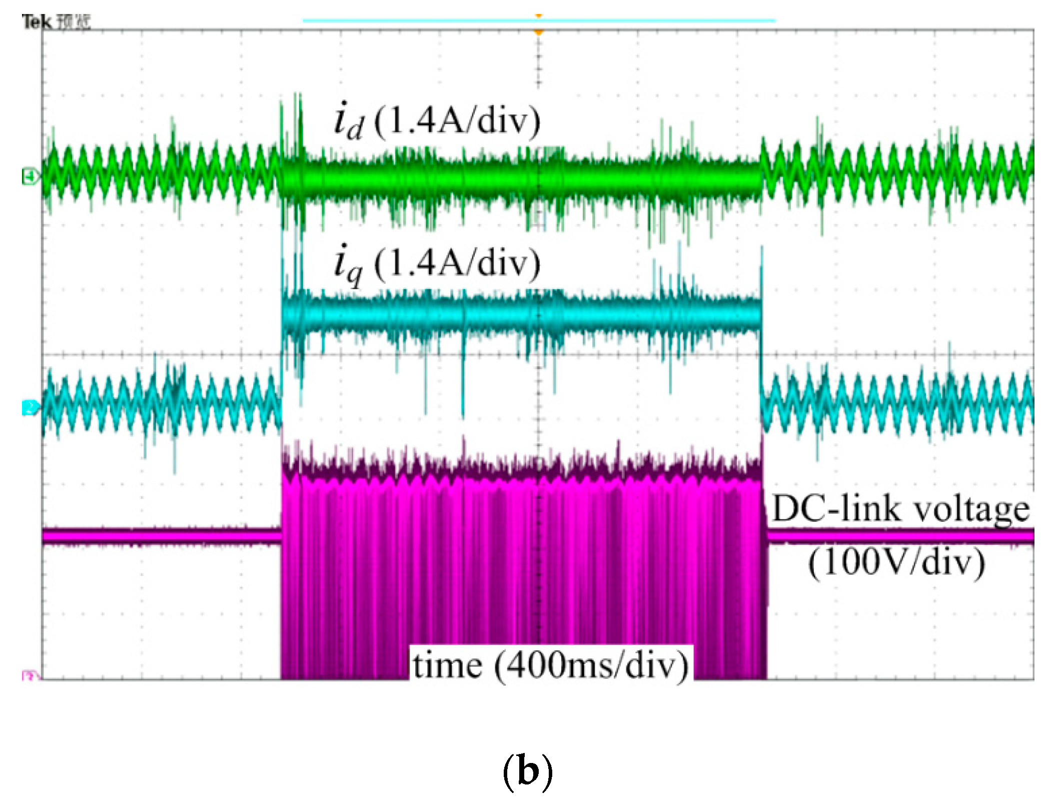
5. Experimental Results
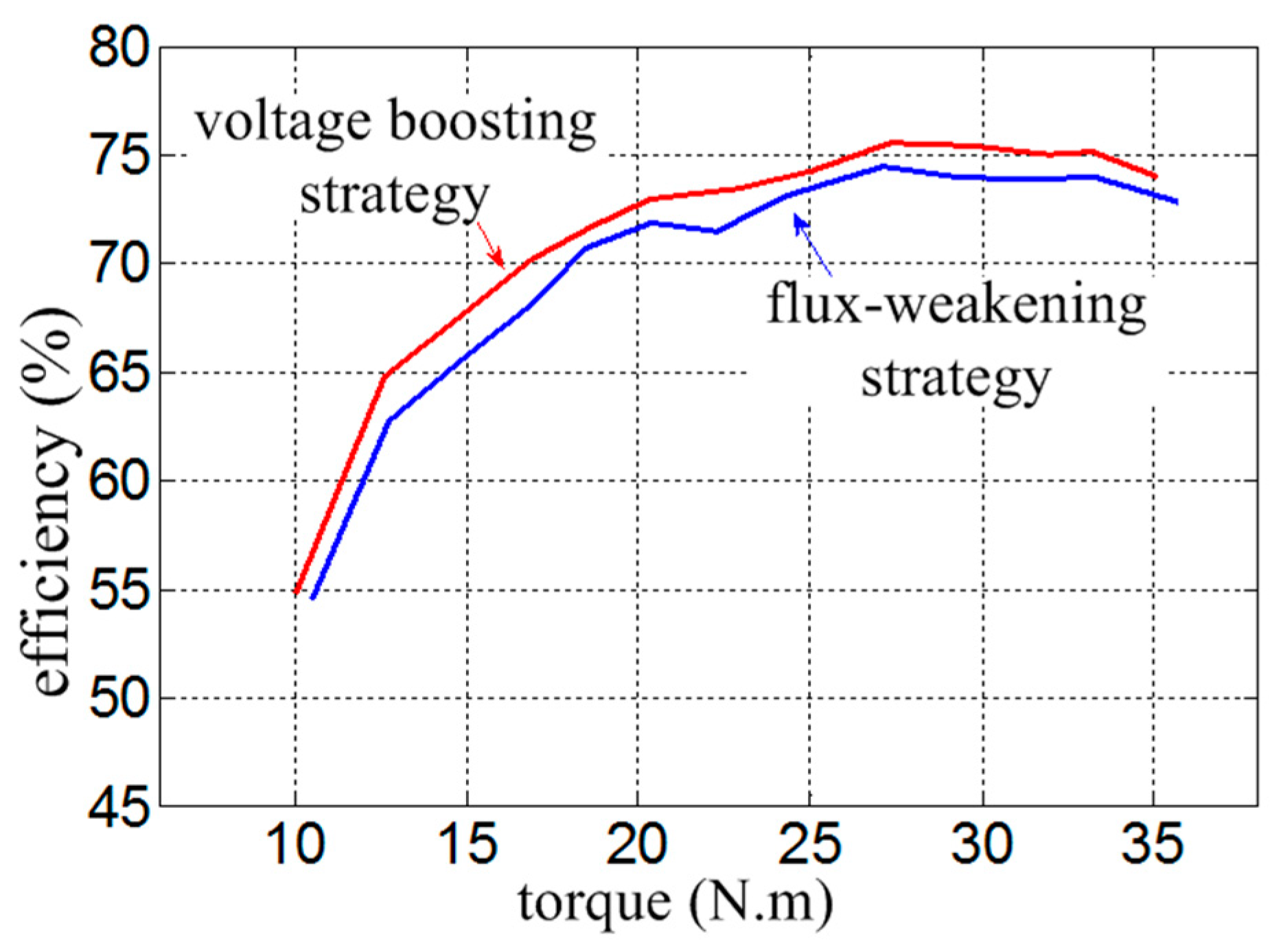
In the experiment, two motors were used to drag each other to realize the PMSM loading. The experimental platform is shown in Figure 4. Figure 4a shows the power circuit and its control circuit of the Z-Source inverter, and Figure 4b shows the motor-to-motor system. A torque and speed measuring instrument was installed in the middle of the two motors to measure the torque, speed, and mechanical power of the motor system in real time.
The experimental results of steady-state characteristics of Z-Source inverter and motor are shown in Figure 5. As shown in Figure 5, the system can achieve a stable working state. The inductor current has four charging and discharging processes within a carrier cycle.
Figure 6 and Figure 7 show the experimental results of dynamic characteristics of Z-Source inverter and motor.
As shown in Figure 6 and Figure 7, the response time of DC-link voltage is about 10 ms and the overshoot is about 3%, indicating good dynamic characteristics. After the input voltage was changed, the DC-link voltage can still follow the given voltage, 300 V, indicating that ZSI realized the voltage closed loop. The loading and unloading experimental results of the motor indicated good steady-state response characteristics of inductor current.
Figure 8 shows the relevant experimental waveforms in the case of the flux-weakening scheme and the voltage boosting scheme using the Z-Source inverter. During the experiment, the DC input voltage of both groups was set at 200 V. In one experimental group, the voltage boosting scheme was adopted to increase the bus voltage. In the other experimental group, the flux-weakening scheme was adopted to achieve a wide speed range. The d- and q-axis currents in Figure 8 are shown as D/A outputs, 1.4 ampere per voltage.
Figure 9 shows the efficiency comparison of the flux-weakening scheme and the Z-Source inverter scheme under different rotational speeds. As shown in Figure 9, compared with the flux-weakening scheme, the Z-Source inverter scheme can achieve the higher efficiency.

6. Discussion

In this paper, a bus voltage-adjustable PMSM drive system based on voltage-type Z-Source inverter was designed and a double-loop control strategy composed of the inner loop of inductive current and outer loop of capacitor voltage was carried out on the inverter side of Z-Source. The experimental results showed that the system had good dynamic and steady-state characteristics.
Several new dead zone compensation strategies were proposed in References [28,29,30], and the motor current quality has been improved under light load. However, it is hard to get satisfactory compensation effects under wide load working conditions and the compensation proposal increases the control complex. Due to its inherent immunity to short circuit, the proposed Z-Source inverter does not need any dead zone compensation. Therefore, the harmonic content of the current waveform can be as low as 2%. In the flux-weakening scheme, the required current amplitude is larger under the same motor working condition, thus resulting in the greater copper loss. In the Z-Source inverter scheme, the required current amplitude is smaller and the corresponding copper loss is smaller so the efficiency is about 3% higher than that of the flux-weakening scheme.
References [31,32,33] adopted the DC–DC converter to adjust the resonant converter voltage, and the output current can be realized by changing the duty ratio. In this paper, the Z-Source inverter was used to increase the DC-link voltage so that the torque and speed range of the motor could be expanded. Both DC-DC converters and Z-Source converters can adjust the DC-link voltage, whereas Z-Source converters have the higher reliability.
The Z-Source network requires two inductors and capacitors, one more inductor than the DC/DC converter. The greater the power of the controller is, the lower the switching frequency will be to reduce the switching loss. In order to avoid saturation, the volume of magnetic core and coil radius will have to be increased, which will ultimately affect the volume and weight of the inductor. For example, the weight of inductor used in this paper is about 1 kg. We can use coupling technology to reduce the number of inductors to one [34], but attention should be paid to avoid the adverse effects caused by leakage.
The proposed Z-Source converter voltage boosting scheme can be applied to the electric vehicles, photovoltaic power generation, motor speed regulation, and other fields. At present, new converter structures such as small number of devices, small volume, high boost ratio, and small startup impact are proposed by relevant scholars. In the control mode, single closed-loop and double closed-loop control strategies gradually replace the open-loop structure, and intelligent control strategies such as sliding mode control and fuzzy control are also being applied to Z-Source inverters.

7. Conclusions

Compared with the other solutions, the proposed Z-Source inverter system does not need demagnetization current, which leads to increase in the system capacity and decrease in the system efficiency. The required current amplitude is smaller, and the efficiency is about 3% higher than that of flux-weakening scheme when the PMSM speed was set to 650 r/min. Based on the comprehensive design, the response time of DC-link voltage is 10 ms and the overshoot is 3%. Although the volume of the inductor was big (about 1kg), it may be reduced by the inductor coupling technology.

Author Contributions

Conceptualization, D.S.; methodology, D.S.; simulation and experiments, D.S. and M.H.; writing—original draft preparation, D.S.; writing—review and editing, W.R. and Z.Q.

Funding

This research was funded by the Fundamental Research Funds for the Central Universities (Grant No.HIT.NSRIF.2019022).

Acknowledgments

The authors would like to thank the editors and reviewers for their constructive comments in revising this paper.

Conflicts of Interest

The authors declare no conflict of interest.

References

  1. Pan, Z.; Shieh, S.; Li, B. Battery State-of-Charge Pulse-and-Glide Strategy Development of Hybrid Electric Vehicles for VTS Motor Vehicle Challenge. In Proceedings of the 2018 IEEE Vehicle Power and Propulsion Conference (VPPC), Chicago, IL, USA, 27–30 August 2018; pp. 1–7. [Google Scholar]
  2. Mercorelli, P. An adaptive and optimized switching observer for sensorless control of an electromagnetic valve actuator in camless internal combustion engines. Asian J. Control 2014, 16, 959–973. [Google Scholar] [CrossRef]
  3. Braune, S.; Liu, S.; Mercorelli, P. Design and control of an electromagnetic valve actuator. In Proceedings of the 2006 IEEE Conference on Computer Aided Control System Design, 2006 IEEE International Conference on Control Applications, 2006 IEEE International Symposium on Intelligent Control, Munich, Germany, 4–6 October 2006; pp. 1657–1662. [Google Scholar]
  4. Mercorelli, P.; Lehmann, K.; Liu, S. Robust flatness based control of an electromagnetic linear actuator using adaptive PID controller. In Proceedings of the 42nd IEEE International Conference on Decision and Control, Maui, HI, USA, 9–12 December 2003; pp. 3790–3795. [Google Scholar]
  5. Xu, Y.; Morito, C.; Lorenz, R.D. Extending High-Speed Operating Range of Induction Machine Drives using Deadbeat-Direct Torque and Flux Control with Precise Flux Weakening. IEEE Trans. Ind. Appl. 2019, 55, 3770–3780. [Google Scholar] [CrossRef]
  6. Zhao, H.; Liu, C.; Song, Z.; Liu, S. A Consequent-Pole PM Magnetic-Geared Double-Rotor Machine With Flux-Weakening Ability for Hybrid Electric Vehicle Application. IEEE Trans. Magn. 2019, 55, 1–7. [Google Scholar] [CrossRef]
  7. Peng, F.Z. Z-source inverter. IEEE Trans. Ind. Appl. 2003, 39, 504–510. [Google Scholar] [CrossRef]
  8. Babaei, E.; Asl, E.S. Steady-state analysis of high-voltage gain multiple series Z-source inverter. IET Power Electron. 2017, 10, 1518–1528. [Google Scholar] [CrossRef]
  9. Bussa, V.K.; Ahmad, A.; Singh, R.K.; Mahanty, R. Single-phase high-voltage gain switched LC Z-source inverters. IET Power Electron. 2018, 11, 796–807. [Google Scholar] [CrossRef]
  10. Zhu, X.; Zhang, B.; Qiu, D. Enhanced boost quasi-Z-source inverters with active switched-inductor boost network. IET Power Electron. 2018, 11, 1774–1787. [Google Scholar] [CrossRef]
  11. Serpi, A.; Fois, G.; Porru, M.; Damiano, A. Flux-Weakening Space Vector Control Algorithm for Permanent Magnet Brushless DC Machines. In Proceedings of the 2018 IEEE Vehicle Power and Propulsion Conference (VPPC), Chicago, IL, USA, 27–30 August 2018; pp. 1–6. [Google Scholar]
  12. Zhang, Z.; Wang, C.; Zhou, M.; You, X. Flux-Weakening in PMSM Drives: Analysis of Voltage Angle Control and the Single Current Controller Design. IEEE J. Emerg. Sel. Top. Power Electron. 2019, 7, 437–445. [Google Scholar] [CrossRef]
  13. Chen, X.; Pise, A.A.; Elmes, J.; Batarseh, I. Ultra-Highly Efficient Low Power Bi-directional Cascaded-Buck-Boost Converter for Portable PV-Battery-Devices Applications. IEEE Trans. Ind. Appl. 2019, 55, 3989–4000. [Google Scholar] [CrossRef]
  14. Guha, A.; Narayanan, G. Impact of Undercompensation and Overcompensation of Dead-Time Effect on Small-Signal Stability of Induction Motor Drive. IEEE Trans. Ind. Appl. 2018, 54, 6027–6041. [Google Scholar] [CrossRef]
  15. Guha, A.; Narayanan, G. Impact of Dead Time on Inverter Input Current, DC-Link Dynamics, and Light-Load Instability in Rectifier-Inverter-Fed Induction Motor Drives. IEEE Trans. Ind. Appl. 2018, 54, 1414–1424. [Google Scholar] [CrossRef]
  16. Panfilov, D.; Husev, O.; Blaabjerg, F.; Zakis, J.; Khandakji, K. Comparison of three-phase three-level voltage source inverter with intermediate dc–dc boost converter and quasi-Z-source inverter. IET Power Electron. 2016, 9, 1238–1248. [Google Scholar] [CrossRef]
  17. Li, J.; Liu, J.; Liu, Z. Comparison of Z-source inverter and traditional two-stage boost-buck inverter in grid-tied renewable energy generation. In Proceedings of the 2009 IEEE 6th International Power Electronics and Motion Control Conference, Wuhan, China, 17–20 May 2009; pp. 1493–1497. [Google Scholar]
  18. Wang, R.; Jia, X.; Dong, S.; Zhang, Q. PMSM driving system design for electric vehicle applications based on bi-directional quasi-Z-source inverter. In Proceedings of the 2018 13th IEEE Conference on Industrial Electronics and Applications (ICIEA), Wuhan, China, 31 May–2 June 2018; pp. 1733–1738. [Google Scholar]
  19. Dong, S.; Zhang, Q.; Cheng, S. Inductor Current Ripple Comparison Between ZSVM4 and ZSVM2 for Z-Source Inverters. IEEE Trans. Power Electron. 2016, 31, 7592–7597. [Google Scholar] [CrossRef]
  20. Dong, S.; Zhang, Q.; Cheng, S. Analysis of Critical Inductance and Capacitor Voltage Ripple for a Bidirectional Z-Source Inverter. IEEE Trans. Power Electron. 2015, 30, 4009–4015. [Google Scholar] [CrossRef]
  21. Li, K.; Wang, Y. Maximum Torque per Ampere (MTPA) Control for IPMSM Drives Using Signal Injection and an MTPA Control Law. IEEE Trans. Ind. Inform. 2019. [Google Scholar] [CrossRef]
  22. Lin, F.; Huang, M.; Chen, S.; Hsu, C. Intelligent Maximum Torque per Ampere Tracking Control of Synchronous Reluctance Motor Using Recurrent Legendre Fuzzy Neural Network. IEEE Trans. Power Electron. 2019. [Google Scholar] [CrossRef]
  23. Mosaddegh, H.; Zarchi, H.A.; Markadeh, G.A. Stator Flux Oriented Control of Brushless Doubly Fed Induction Motor Drives Based on Maximum Torque per Total Ampere Strategy. In Proceedings of the 2019 10th International Power Electronics, Drive Systems and Technologies Conference (PEDSTC), Shiraz, Iran, 12–14 February 2019; pp. 84–89. [Google Scholar]
  24. Li, Y.; Jiang, S.; Cintron-Rivera, J.G.; Peng, F.Z. Modeling and Control of Quasi-Z-Source Inverter for Distributed Generation Applications. IEEE Trans. Ind. Electron. 2013, 60, 1532–1541. [Google Scholar] [CrossRef]
  25. Liu, Y.; Ge, B.; Abu-Rub, H.; Peng, F.Z. Modelling and controller design of quasi-Z-source inverter with battery-based photovoltaic power system. IET Power Electron. 2014, 7, 1665–1674. [Google Scholar] [CrossRef]
  26. Yamamoto, K.; Shinohara, K.; Nagahama, T. Characteristics of permanent-magnet synchronous motor driven by PWM inverter with voltage booster. IEEE Trans. Ind. Appl. 2004, 40, 1145–1152. [Google Scholar] [CrossRef]
  27. Yamamoto, K.; Shinohara, K.; Makishima, H. Comparison between flux weakening and PWM inverter with voltage booster for permanent magnet synchronous motor drive. In Proceedings of the Power Conversion Conference-Osaka 2002 (Cat. No.02TH8579), Osaka, Japan, 2–5 April 2002; Volume 1, pp. 161–166. [Google Scholar]
  28. Lai, G.; Liu, Z.; Zhang, Y.; Chen, C.L.P.; Xie, S.; Liu, Y. Fuzzy Adaptive Inverse Compensation Method to Tracking Control of Uncertain Nonlinear Systems With Generalized Actuator Dead Zone. IEEE Trans. Fuzzy Syst. 2017, 25, 191–204. [Google Scholar] [CrossRef]
  29. Meng, D.; Li, A.; Lu, B.; Tang, C.; Li, Q. Adaptive Dynamic Surface Control of Pneumatic Servo Systems With Valve Dead-Zone Compensation. IEEE Access 2018, 6, 71378–71388. [Google Scholar] [CrossRef]
  30. Shi, W.; Zhao, H.; Ma, J.; Yao, Y. Dead-Zone Compensation of an Ultrasonic Motor Using an Adaptive Dither. IEEE Trans. Ind. Electron. 2018, 65, 3730–3739. [Google Scholar] [CrossRef]
  31. Iuga, B.; Tirnovan, R.A. Variable High Frequency Power Inverter used in Wireless Power Transfer. In Proceedings of the 2019 8th International Conference on Modern Power Systems (MPS), Cluj Napoca, Romania, 21–23 May 2019; pp. 1–3. [Google Scholar]
  32. Kim, D.; Ahn, D. Self-Tuning LCC Inverter Using PWM-Controlled Switched Capacitor for Inductive Wireless Power Transfer. IEEE Trans. Ind. Electron. 2019, 66, 3983–3992. [Google Scholar] [CrossRef]
  33. Lee, A.T.L.; Jin, W.; Tan, S.; Hui, S.Y. Buck-Boost Single-Inductor Multiple-Output High-Frequency Inverters for Medium-Power Wireless Power Transfer. IEEE Trans. Power Electron. 2019, 34, 3457–3473. [Google Scholar] [CrossRef]
  34. Samadian, A.; Hosseini, S.H.; Sabahi, M.; Maalandish, M. A New Coupled Inductor Non-isolated High step up Quasi Z-Source DC-DC Converter. IEEE Trans. Ind. Electron. 2019. [Google Scholar] [CrossRef]
Figure 1. Z-Source inverter.
Energies 12 03350 g001
Figure 2. Control block diagram of Z-Source drive PMSM system.
Energies 12 03350 g002
Figure 3. Bode plots for the transfer functions with and without compensation: (a) Inductor current; (b) DC-link voltage.
Energies 12 03350 g003aEnergies 12 03350 g003b
Figure 4. Test bench (a) Z-Source inverter; (b) PMSM.
Energies 12 03350 g004
Figure 5. Steady state waveforms of ZSI (a) In load cycle; (b) In carrier cycle.
Energies 12 03350 g005aEnergies 12 03350 g005b
Figure 6. Transient waveforms in starting period: (a) Motor current and DC-link voltage; (b) Inductor current and DC-link voltage.
Energies 12 03350 g006
Figure 7. ZSI waveforms with varying working condition (a) With varying input voltage; (b) With load and unload.
Energies 12 03350 g007
Figure 8. d- and q-axis current and DC-link voltage with different strategies: (a) Flux-weakening strategy; (b) Voltage boosting strategy.
Energies 12 03350 g008aEnergies 12 03350 g008b
Figure 9. Efficiency comparison with different strategies at 650 r/min.
Energies 12 03350 g009
Table 1. Parameters of permanent magnet synchronous motor (PMSM).
ParameterValueParameterValue
normal power (kW)2.45nominal torque (N·m)33.5
nominal voltage (V)220d-axis inductance (mH)5.3
rated speed (r/min)700q-axis inductance (mH)10.5
magnet flux (Wb)0.425poles4
Table 2. Parameters of the ZSI.
InductorCapacitorIGBT
Inductance (mH)Rated Current (A)Capacitance (µF)Rated Voltage (V)Rated Voltage (V)Rated Current (A)
1.23555045060050

