Article

Synthesis of Bi2O3-MnO2 Nanocomposite Electrode for Wide-Potential Window High Performance Supercapacitor

1
Department of Materials Science and Engineering, Pusan National University, San 30 Jangjeon-dong, Geumjeong-gu, Busan 46241, Korea
2
Global Frontier R&D Center for Hybrid Interface Materials, Pusan National University, 30 Jangjeon-dong, Geumjung-gu, Busan 46241, Korea
3
National Core Research Centre (NCRC), Pusan National University, Geumjeong-gu, Busan 46241, Korea
*
Author to whom correspondence should be addressed.
Energies 2019, 12(17), 3320; https://doi.org/10.3390/en12173320
Submission received: 15 July 2019 / Revised: 23 August 2019 / Accepted: 24 August 2019 / Published: 28 August 2019
(This article belongs to the Section D1: Advanced Energy Materials)

Abstract

:
In this work, we report the synthesis of a Bi2O3-MnO2 nanocomposite as an electrochemical supercapacitor (ES) electrode via a simple, low-cost, eco-friendly, and low-temperature solid-state chemical process followed by air annealing. This as-synthesized nanocomposite was initially examined in terms of its structure, morphology, phase purity, and surface area using different analytical techniques and thereafter subjected to electrochemical measurements. Its electrochemical performance demonstrated excellent supercapacitive properties in a wide potential window. Its specific capacitance was able to reach 161 F g−1 at a current density of 1A g−1 and then showed a superior rate capability up to 10 A g−1. Furthermore, it demonstrated promising cycling stability at 5 A g−1 with 95% retention even after 10,000 charge–discharge cycles in a wide potential window of 1.3 V, evidencing the synergistic impact of both Bi2O3 and MnO2 in the Bi2O3-MnO2 ES electrode. Additionally, the practical reliability of the envisioned electrode was ascertained by the fabrication of a symmetric Bi2O3-MnO2//Bi2O3-MnO2 pencil-type supercapacitor device that displayed an energy density of 18.4 Wh kg−1 at a power density of 600 W kg−1 and a substantial cyclic stability up to 5000 cycles. Subsequently, an LED was also powered at its full brightness using three of these devices connected in series in order to demonstrate the real-time application of the Bi2O3-MnO2 ES electrode.

Graphical Abstract

1. Introduction

During the past few years, there has been a dramatic increase in research activities directed at developing high-performance energy storage devices due to their increasingly important role in our daily life and energy driven society [1,2,3,4,5]. Among the different available energy storage devices, electrochemical supercapacitors (ESs) have attracted considerable interest due to their myriad technological applications on account of their unique properties, i.e., fast charging and discharging, long cycle life, high reliability, and ability to deliver high power density than conventional batteries. In recent years, researchers have extensively worked to develop different ES electrode materials via several different synthesis methods such as dc-plasma reaction, solution-derived synthesis, molecular beam epitaxy, chemical vapor deposition, sputtering, thermal evaporation, and many others [6,7,8,9,10]. It should be noted that these synthesis methods are impressive but require specific experimental conditions, complicated and expensive instrumental setups, they involve strict environmental controls, and also provide only limited yields of the synthesized product. Therefore, to enable the production of ES electrode materials on a large scale, it is highly desirable that a synthesis route should be adopted that is economically viable and facile. Among the different available routes fulfilling these requirements such as the sol-gel route [11] and the co-precipitation method [12], the solid state chemical synthesis route is one of the simplest and extensively used methods for developing various types of materials for different applications [13,14]. Importantly, this method has seldom been explored for the development of ES electrode materials.
Previously, the majority of the electrode materials envisaged fall mainly into three categories: Metal oxides or hydroxides, carbonaceous materials, and conducting polymers. By contrast, metal oxide/hydroxide-based electrode materials are relatively economic and eco-friendly. Especially, by virtue of their synergistic effects, nanocomposites of metal oxides/hydroxides have proven to be remarkable as ES electrode materials [15,16]. However, it is important to avoid the use of expensive rare earth metal oxides/hydroxides and those materials which have environmental hazards associated with them. Among the different types of metal oxide materials that can serve as ES electrodes, bismuth oxide (Bi2O3) is known to be a promising negative ES electrode material owing to its multiple oxidation states, biocompatibility, and non-toxicity [17,18]. Additionally, the alternating layered structure of Bi2O3 makes it an interesting host for ion storage, encouraging its employment for energy storage applications. On the other side, manganese dioxide (MnO2) has drawn enormous research interest owing to its high theoretical capacitance, environmental friendliness, and great abundance [19,20,21]. More importantly, it also provides a wide positive potential window in an aqueous electrolyte, resulting in high-energy-density ES devices [22]. Looking at the intriguing properties of both these materials, it would be interesting to explore nanocomposites of these materials as ES electrodes, capitalizing on their dissimilar opposite electrochemical potential windows to form a single wide potential window. Previously, Ma et al. [23] reported bismuth oxide @ manganese oxide nanocomposite electrodes for ES applications. However, the obtained nanocomposite was unable to show any surprising supercapacitive performance. Similar work was reported by Chi et al., who also could not achieve excellent performance from their nanocomposites [24]. Moreover, in both the cases, there was a need for a special apparatus arrangement to synthesize the nanocomposites, inhibiting their facile and large-scale production.
We, therefore, in the present work, report a facile solid-state chemical synthesis approach to prepare Bi2O3-MnO2 nanocomposite as an ES electrode with a wide potential window. This synthesis process is inexpensive, environmentally friendly, and easily scalable. The as-synthesized Bi2O3-MnO2 nanocomposite was characterized to determine its phase purity, structure, morphology, and surface area. After different characterizations, electrochemical measurements were conducted using a three-electrode configuration to measure its specific capacitance, rate capability, and cycling stability. Further, Bi2O3-MnO2 ES electrode was used to design a symmetric device, installed as a positrode (i.e., positive electrode) and negatrode (i.e., negative electrode), offering a superior energy density of 18.4 Wh kg−1 at a power density of 600 W kg−1 with a cycliing stability up to 5000 cycles retaining almost 96% of its initial energy density. The promising electrochemical performance obtained for this device and its successful use for powering an LED show the potential of the Bi2O3-MnO2 nanocomposite as an ES electrode.

2. Experimental Details

2.1. Materials

All reagents used in the present work were of analytical grade and used without further purification. Bismuth chloride (BiCl3 >98%), manganese chloride tetrahydrate (MnCl2·4H2O >98%), and sodium hydroxide (NaOH >98%) were purchased from Sigma Aldrich. Deionized (DI) water obtained from Millipore was used throughout the experiments as a solvent.

2.2. Method of Synthesis

The Bi2O3-MnO2 nanocomposite was synthesized by using a solid-state chemical synthesis route in the presence of two readily available and low-cost reactants, i.e., BiCl3, and MnCl2·4H2O, and NaOH. In a typical synthesis, 4 g of each metal precursor in powder form and 2 g of NaOH (2:1 w/w) were ground together using agate and mortar for 15–20 min. A thick, slurry kind of paste was obtained after completion of the reaction. The paste was washed grossly dispersing it into water, and then centrifuged for product separation. This process was repeated three times before the final product was obtained. After washing, the product was dried at 60 °C in oven and then annealed at 300 °C for 1 h in a horizontal tube furnace.

2.3. Fabrication of ES Electrode and Full-Cell Device Assembly

Fabrication of ES electrodes was done by mixing active material (final product obtained after annealing) with acetylene black and a polytetrafluoroethylene (PTFE) suspension (60 wt.%) as a binder at a weight ratio of 8:1:1, and then pressing this mixture onto a nickel foam substrate (20 MPa) serving as a current collector. The mass loading of the active material on the Ni foam was approximately 3 mg cm−2. Thereafter, it was dried in a vacuum oven at 60 °C for 12 h before using it as a working electrode in a three-electrode configuration for electrochemical measurements. Later on, to fabricate a full-cell device configuration, two similar working electrodes were stacked together separated by a piece of filter paper soaked in 1 M NaOH liquid electrolyte. The prepared assembly is denoted as a Bi2O3-MnO2 // Bi2O3-MnO2 pencil-type symmetric ES device.

2.4. Material Characterizations

The X-ray diffraction (XRD) pattern used to characterize the Bi2O3-MnO2 nanocomposite was obtained using a D8-Discovery Bruker diffractometer with a Cu-Kα source (λ = 1.5405 Å) operated at a voltage of 40 kV and a current of 40 mA. The surface morphology of the nanocomposite and the elements present therein were examined using a field-emission scanning electron microscope (FESEM, Hitachi, S-4800, 15 kV) equipped with an energy dispersive X-ray spectrometer (EDX). During EDX operation, the probe was focused to 0.2 nm and a camera length of 20 cm was used. Transmission electron microscopy (TEM), high-resolution TEM (HRTEM), and scanning TEM (STEM) images were also recorded using an FEI Tecnai F20. Brunauer–Emmett–Teller (BET) measurements were performed on a Micromeritics ASAP 2010 analyzer to confirm the type of porosity and the surface area of the nanocomposite. The pore size distributions of all the samples were confirmed from Barrett–Joyner–Halenda (BJH) plots. X-ray photoelectron spectroscopy, (XPS, VG Scientifics ESCALAB250) calibrated to a carbon peak (C 1s) located at 284.6 eV, was used to analyze the composition and valence states of the ions present over the surface of the Bi2O3-MnO2 nanocomposite.

2.5. Electrochemical Measurements

Electrochemical measurements of the Bi2O3-MnO2 ES electrode and its device assembly were carried out on an Ivium-n-Stat electrochemical workstation (Ivium, The Netherlands). The electrode was subjected to cyclic voltammetry (CV), galvanostatic charge–discharge (GCD), and electrochemical impedance spectroscopy (EIS) measurements, as the working electrode, in a three-electrode configuration containing 1 M aqueous NaOH electrolyte. A piece of platinum foil (facing towards the working electrode) and a saturated Hg/HgO electrode served as the counter and the reference electrodes, respectively. The distance between the working electrode and the counter electrode was fixed to be ∼1 cm. The EIS response was recorded in the frequency range of 100 kHz–0.01 Hz with an AC voltage amplitude of 5 mV. Similarly, the constructed device was employed on the same station using two terminals for its electrochemical measurements. Calculations of the specific capacitance, energy density, and power density were done similarly to the calculations in our previously reported paper [25] using the following equations:
C E =   I   Δ t m   Δ V   ; C d e v i c e =   I   Δ t m t   V
E =   1 2 C d e v i c e   V 2
P = E Δ t   × 3600
where, CE and Cdevice are the specific capacitances in F g−1 for the electrode and device calculated from their respective charge– discharge curves, I is the charge– discharge current, Δ t is the discharging time, m is the mass of active material, mt is the mass of total electrode material, Δ V is the potential window of the half-cell, V is the voltage of the charge–discharge curve measured for the symmetric device, and E and P are the energy density and power density in terms of Wh kg−1 and W kg−1 of the symmetric device, respectively.

3. Results and Discussion

3.1. Structural Analysis

The structure and phases present in the Bi2O3-MnO2 nanocomposite were confirmed from the XRD pattern shown in Figure 1 (4th from the bottom row). To clearly show the presence of MnO2 in the Bi2O3-MnO2 nanocomposite, we also present the XRD pattern of Bi2O3 prepared by the same solid-state synthesis route in Figure 1 (3rd from the bottom row). The XRD patterns of both samples have been indexed using Bi2O3 and MnO2 standard reference patterns reported in JCPDS No: 027-0053 and JCPDS No: 053-0633, respectively, shown in Figure 1 (bottom row and 2nd from bottom row). The XRD pattern corresponding to Bi2O3, scanned within the range of 2θ = 15–50°, matches well with its reported standard reference pattern. All the peaks are clearly visible and can be well indexed to a monoclinic phase with P21/c space group.
The two most prominent peaks observed at 2θ values of 27.3° and 33.2° exhibits d-spacings of 3.25 Å and 2.71 Å and therefore correspond to the (-121) and (-202) reflection planes of Bi2O3, respectively. Further, the XRD pattern of Bi2O3-MnO2 was also scanned within the same 2θ range and matches well with the expected Bi2O3 reflection planes, except for one additional peak. This additional peak appearing at 2θ values of 30.1° is the peak of the Bi(OH)3 phase present as an impurity in the synthesized material.
Moreover, we can also notice two peaks for MnO2, among which one of the peaks at 27.3° coincides with the most prominent peak observed for Bi2O3, and exhibits d-spacings of 3.26 Å. The other peak appearing at 37.0° is the most prominent peak of MnO2 according to the standard reference pattern in the respective JCPDS card exhibiting d-spacing of 2.42 Å. These peaks therefore correspond to the (310) and (330) reflection planes of MnO2, respectively. The well matching peaks can be indexed to a tetragonal lattice system. Thus, the XRD pattern confirms the presence of two distinct phases, i.e., Bi2O3 and MnO2, in the Bi2O3-MnO2 sample, confirming the formation of a nanocomposite. Additionally, a larger full width at half maximum (FWHM) can be seen for the peaks in the XRD pattern of the Bi2O3-MnO2 nanocomposite in comparison to the XRD pattern of Bi2O3, which suggests the nanocomposite has a finer crystallite size. Furthermore, no impurity phase peaks were found in the diffraction pattern except one from the Bi(OH)3 phase. Therefore, it confirms the phase purity of the nanocomposite.

3.2. Electronic States and Chemical Composition Confirmation

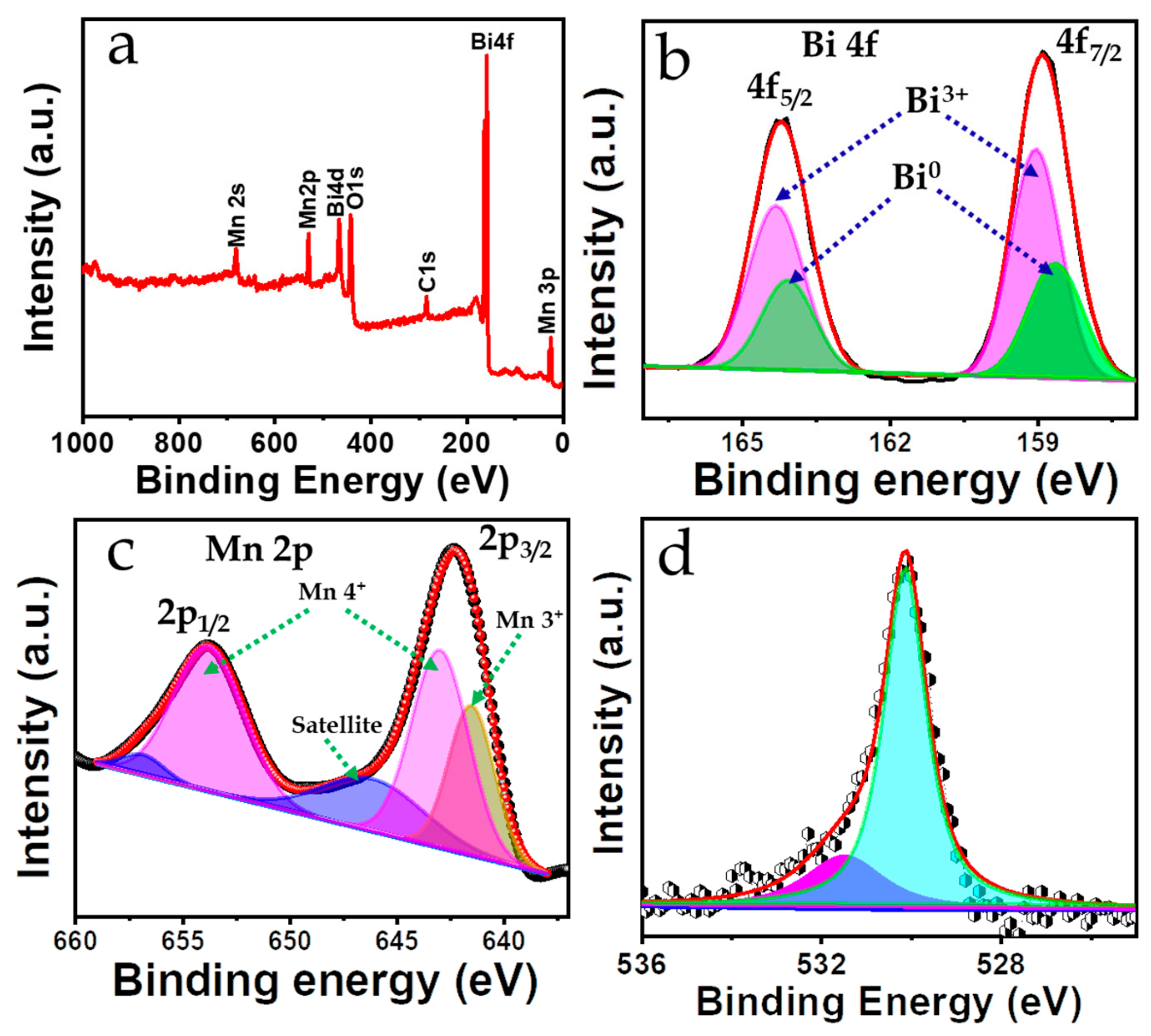
The surface electronic states and chemical compositions were obtained from XPS analysis, shown in Figure 2a, where the presence of Bi, Mn, and O is evidenced without any impurity elements, suggesting the formation of Bi–Mn–O based nanocomposite. The high-resolution XPS spectra of Bi 4f, Mn 2p, and O 1s are shown in Figure 2b–d. Figure 2b shows the Bi 4f core level spectrum with two spin–orbit doublet peaks (J= 5/2 and 7/2) centered at 164.2 (Bi 4f5/2) and 158.9 eV(Bi 4f7/2) with a peak separation of 5.3 eV, which is in accordance with the literature, clarifying the existence of Bi in the +3 oxidation state [26]. Further, deconvolution of the above doublet peaks resulted in two sub-peak in each. The pair of peaks at 164.3, and 159 eV with a peak separation of 5.3 eV is in correlation with the extant cited literature, confirming the presence of Bi2O3 phase in the sample. Additionally, the pair of peaks at lower binding energies 164 and 158.6 eV with the peak separation of 5.6 eV can be assigned to Bi0 state of metallic Bi 4f [27].
Similarly, Figure 2c shows the spin–orbit doublet of Mn 2p (j = 3/2, 1/2) centered at 641.9 (Mn 2p3/2) and 653.7 eV (Mn 2p1/2) with a peak separation of 11.8 eV, indicating the existence of the Mn4+ oxidation state [28,29]. Again, the deconvolution of spin–orbit peaks indicate the co-exitance of Mn4+ and Mn3+ valence state at 642.9 and 641.4 eV, respectively. However, higher peak intensity and larger area under the curve can be noticed for the peak corresponding to Mn4+ state in comparison to peak corresponding to Mn3+ state, confirms the presence of major phase as MnO2 along with partially surface oxidized Mn2O3 phase in the sample [30]. Further, the deconvoluted O 1s spectrum presented in Figure 2d manifests two peaks located at 530.1 and 531.5 eV due to lattice oxygen and surface-adsorbed oxygen, respectively [31,32,33]. Thus, the XPS data confirms the chemical purity of the sample, and the electronic states of the elements are consistent with the formation of a Bi2O3-MnO2 nanocomposite.

3.3. Structure–Morphology Correlation and Reaction Mechanism

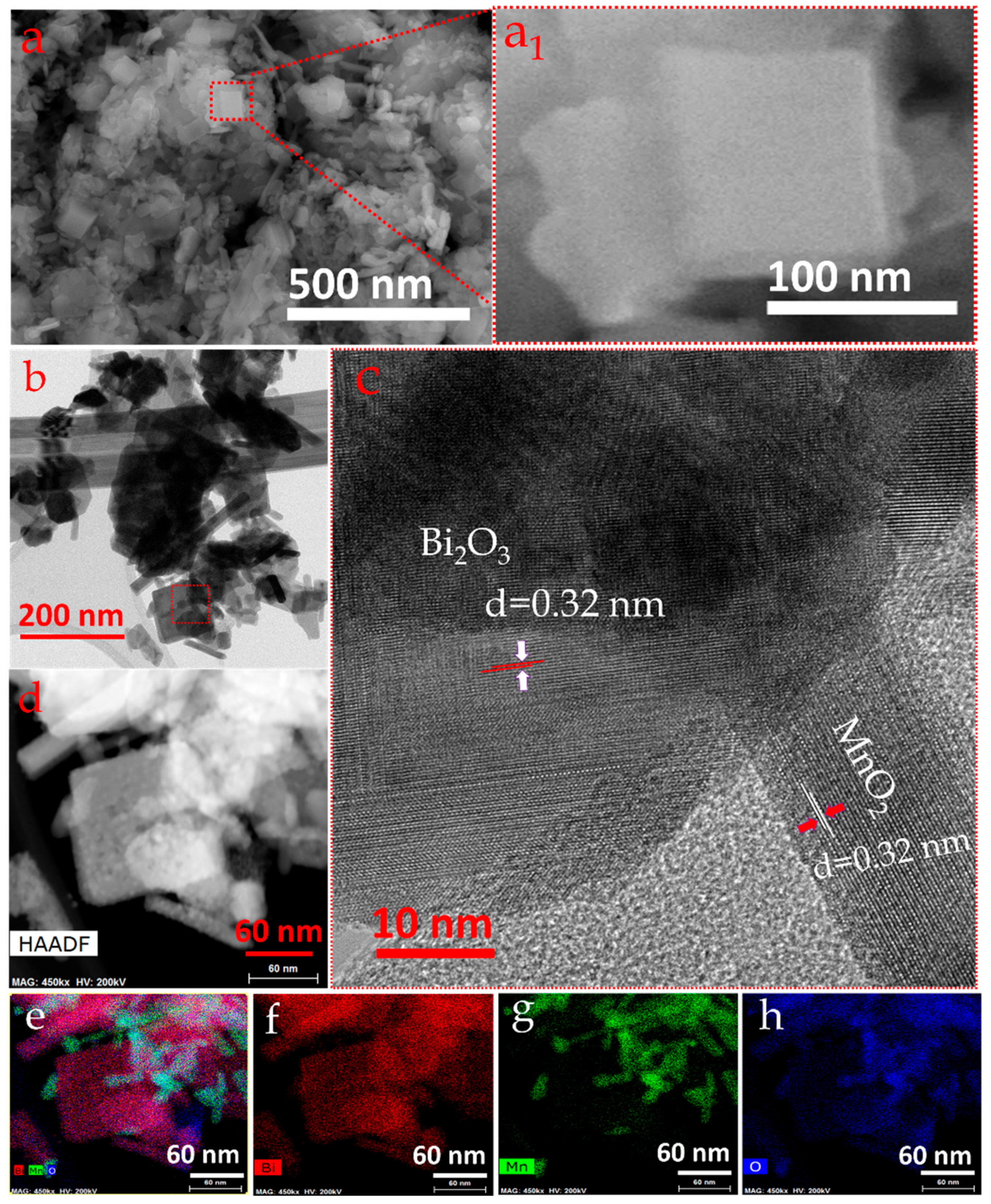
The surface morphology of the as-prepared Bi2O3-MnO2 nanocomposite was initially analyzed using SEM images like that shown in Figure 3a, which highlights the fine nanoplatelet-like structures fused to each other [34]. A magnified image of this morphology shows that these platelets exist in a cubic form (Figure 3a insert). However, agglomeration of nanoplatelets can also be seen, although to a moderate extent only in comparison to the Bi2O3 sample prepared by same solid-state synthesis route (supporting information Figure S1). Again, the morphology and internal structure of these nanoplatelets were analyzed using TEM and HRTEM (Figure 3b) where a big faceted crystal along with a fine elongated nanoparticle were observed. A higher magnification image acquired specifically from the marked square portion is shown in Figure 3c, confirming that the as-formed crystals are highly crystalline and that they consist of two distinct sets of planes. The big faceted cubic-type crystals exhibit a lattice spacing of 2.71 Å corresponding to the (-122) plane of Bi2O3 and a spacing of 2.98 Å corresponding to the (220) plane of MnO2, suggesting the involvement of both Bi2O3 and MnO2 in the Bi2O3-MnO2 composite [35]. Figure 3d shows the high-angle annular dark field (HAADF) image from a particular imaging area of the nanocomposite with a changing brightness at different locations, suggesting the even distribution of the respective elements throughout the sample. The analogous EDX elemental mapping clearly agrees with the HAADF image, showing that the elements of the nanocomposite, i.e., Bi, Mn and O, are seemingly visible as a mixture of three different colors in Figure 3e. Further, the focused mapping of specific elements depicts the separate mapping of Bi in red (Figure 3f), O in blue (Figure 3g), and Mn in green (Figure 3h), affirming the locus of elemental distribution areas in the nanocomposite precisely. Thus, HRTEM analysis and EDX elemental mapping together confirm the formation of a Bi2O3-MnO2 nanocomposite, which is in good agreement with XRD and XPS results. The surface area and porosity of the as-synthesized nanocomposite were also estimated, through BET and BJH measurements, presented in supporting information (Figure S2 and the inbuilt inset), exhibiting a type-IV isotherm and H3-type hysteresis loop (P/P0 ∼0.4).
The measured surface area was 27 m2 g−1, whereas the average pore diameter lies close to 74 Å, suggesting the mesoporous nature of the Bi2O3-MnO2 nanocomposite, which is favorably a good signature since it exposes plenty of electroactive sites to the electrolyte and also facilitates easy migration of electrolyte ions into its near surface area region.
The formation mechanism of the Bi2O3-MnO2 nanocomposite can be described as follows. Initially, NaOH reacts with the metal chloride salts in the presence of environmental moisture due to rigorous mixing of the precursor salt, resulting in the precipitation of metal hydroxides with the evolution of heat [14,36,37]
  BiCl 3 + 3 NaOH Bi OH 3 + 3 NaCl
MnCl 2 · 4 H 2 O + 2 NaOH Mn OH 2 + 2 NaCl + 4 H 2 O
Furthermore, after washing the yield several times, as detailed in the experimental section, a product powder free from reactant impurities is obtained after drying. After air annealing, this powder decomposes and is oxidized by the environmental oxygen, giving rise to the Bi2O3-MnO2 nanocomposite. To ascertain the formation of the hydroxides in the intermediate state (i.e., before annealing) we also took the powder XRD of before annealed sample (supporting information Figure S3) which clearly confirms the presence of bismuth and manganese hydroxide in the sample.
2 Bi OH 3 + Mn OH 2 + xO 2 Δ Bi 2 O 3 + MnO 2 + yH 2 O

3.4. Electrochemical Performance Analysis

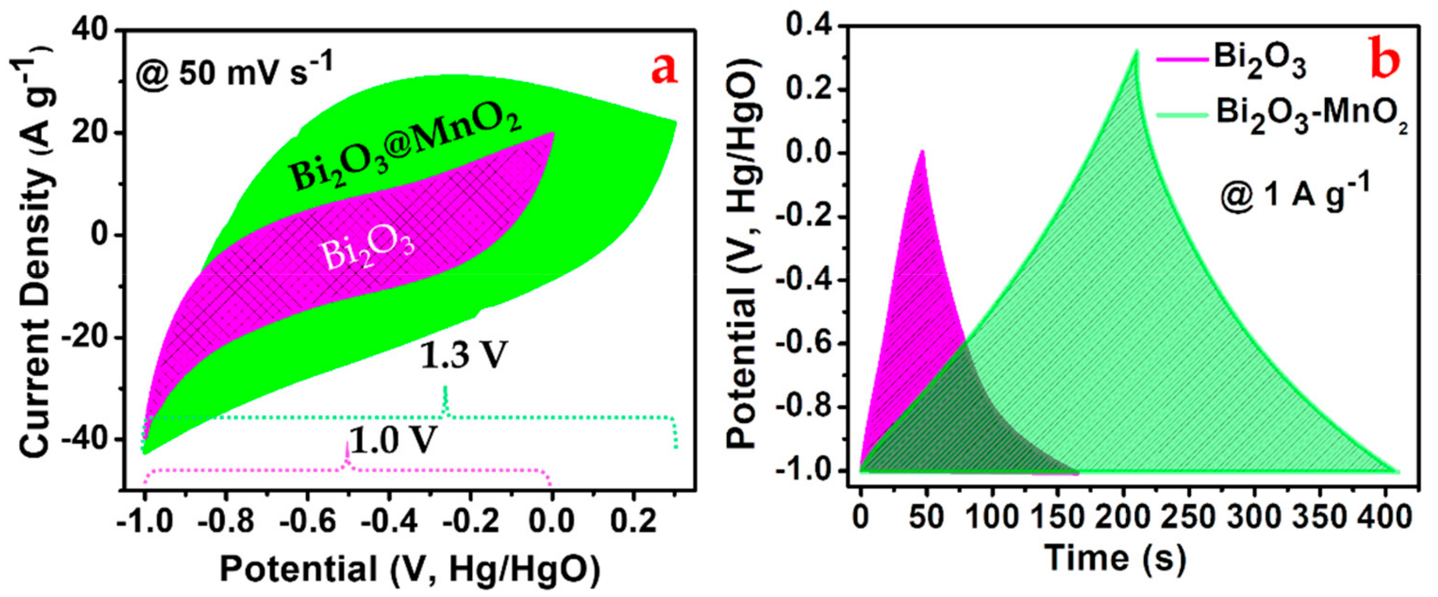
To highlight the benefits of Bi2O3-MnO2 over the Bi2O3 ES electrode synthesized by the same solid-state synthesis route, their CV and GCD performances are compared at a scan rate of 50 mV s−1 and current density of 1 A g−1 in Figure 4a,b, respectively. For the full CV and GCD performances of the Bi2O3 ES electrode, refer to Figure S4 in the supporting information. A 1 M solution of sodium hydroxide (NaOH) was used throughout all the electrochemical measurements. As can be seen from the CV curves, the potential window of the Bi2O3-MnO2 ES electrode was extended by an additional 0.3 V, ensuring that it has the potential to deliver high energy storage ability. Moreover, the same CV also encloses a larger area under its curve with a relatively higher current density response, signifying that the Bi2O3-MnO2 ES electrode is endowed with rich electroactive sites as well as better conductivity. Certainly, this shows that combining Bi2O3 with MnO2 induces a key influence to enhance significant level of capacitive ability in Bi2O3-MnO2 ES electrode. This key influence could be understood more clearly in the Supporting information Figure S5, where, the comparative CV curves for Bi2O3, MnO2 and Bi2O3-MnO2 ES electrode has been presented. Importantly, the enhanced performance in Bi2O3-MnO2 ES electrode doesn’t include any contribution from the Ni-foam, used as a current collector. To ascertain this, CV performance has been compared for Bi2O3-MnO2 ES electrode and bare Ni-foam (supporting information Figure S6) measured in the same electrolyte. Comparison shows that the CV performance obtained for the Ni-foam is almost negligible in compared to CV performance seen for the Bi2O3-MnO2 ES electrode. Therefore, the high electrochemical potential obtained for the Bi2O3-MnO2 ES electrode is a clear vindication of synergetic inclusion of electrochemical performance from the MnO2 ES material. CV and GCD performance of the MnO2 ES electrode is shown in the supporting information Figure S7, evince the idea of individual capacitive as well as energy storage potential of MnO2.
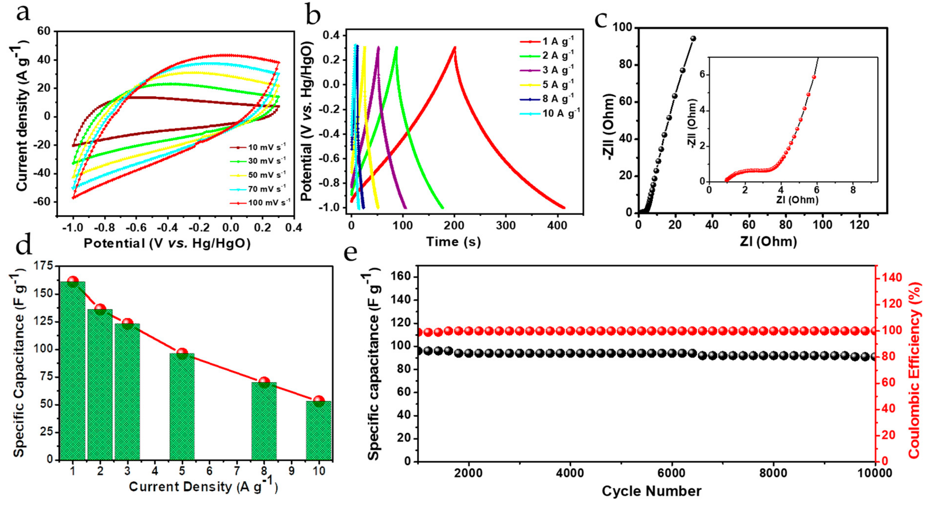
Further, the comparative GCD performances in Figure 4b are in good agreement with the discussed CV results, where a larger potential window and area under the GCD curve were again observed for the Bi2O3-MnO2 ES electrode, confirming its higher energy storage ability. Nevertheless, the commonality between the performances of the two electrodes is their almost linear GCD curves, confirming their capacitive-type energy storage behavior. Figure 5a,b present detailed CV and GCD measurements of the Bi2O3-MnO2 ES electrode. The shapes of the CV curves obtained at different scan rates ranging from 10 (low scan rate) to 100 mV s−1 (high scan rate) demonstrate typical capacitive-type behavior due to impressive charge transport characteristics and easy migration of ions into the near surface region of the electrode material. With increasing scan rate, the shape of the CV curve deviates slightly from its near rectangular appearance, indicating the existence of partial diffusion resistance.
Moreover, despite this partial diffusion resistance evidenced by the CV curves, no significant deformation was observed in the shapes of CV curves obtained after cycling (supporting information in Figure S8a). The characteristics of these CV curves suggest that the capacitive activity originates mainly from the outer surface and near surface region of Bi2O3-MnO2, where charge transfer occurs from the specifically adsorbed ions as well as counter balanced ions to the electrostatically polarized electrode [38]. Due to the involvement of the outer surface and near surface region, diffusion resistance encountered during the forward and backward scans is minimal, which allows the CV curves to retain their shape over a long period of time. Moreover, the CV curves enclose a prominent area within a wide potential range of 1.3 V, indicating the high energy storage ability of the Bi2O3-MnO2 electrode. We can further validate this inference from the GCD curves (Figure 5b), measured by charging and discharging up to a current density of 10 A g−1 without any reduction in the potential window marked for the CV curves.
The linear behavior of the charge-discharge curves is a clear indication of surface and near surface controlled capacitive behavior from the ES electrode. Intriguingly, this capacitive ability has emerged as a consequence of reversible electrostatic as well as Faradaic reactions originating from Bi2O3 and MnO2 in the Bi2O3-MnO2 composite [17,24,39].
MnO 2   +   Na + +   e   MnOO Na +
MnO 2 surface   +   Na + MnOO Na + surface
Bi 2 O 3   +   xNa + +   xe     Na x Bi 2 O 3
Furthermore, the electrochemical behavior of the Bi2O3-MnO2 electrode was also studied based on its EIS performance (Figure 5c), where a very small series resistance of about 0.9 Ω is evidenced from the intercept on the X-axis in the high frequency range. Moreover, the curvature diameter of 2.3 Ω seen in the magnified Nyquist plot corresponds to the interfacial charge–transfer resistance (Rct) between the interface of the electrode and the electrolyte solution. This implies a rapid charge transfer process across the electrolyte/electrode interface, ensuring a large capacitance and good rate capability up to 10 A g−1 from Bi2O3-MnO2 electrode.
In the low frequency region, the straight line exhibiting a slope of more than 45° can be attributed to the excellent capacitive behavior of Bi2O3-MnO2 on account of the surface redox reactions and electric double layer formation, consistent with the CV and GCD results. The rate capability performance of the as-fabricated Bi2O3-MnO2 electrode is presented in Figure 5d. A specific capacitance (SC) of 161 F g−1 at 1A g−1 was obtained from the GCD curves, sustaining an impressive SC up to 53 F g−1 at a relatively high current density of 10 A g−1. Such impressive rate capability performance is due to the fact that a large number of electroactive sites are exposed to the ions present in the electrolyte. However, the decrease in the value of the SC towards higher current density is possibly due to abated participation of electroactive sties in the near surface region during the quick charging- discharging process of the Bi2O3-MnO2 electrode.
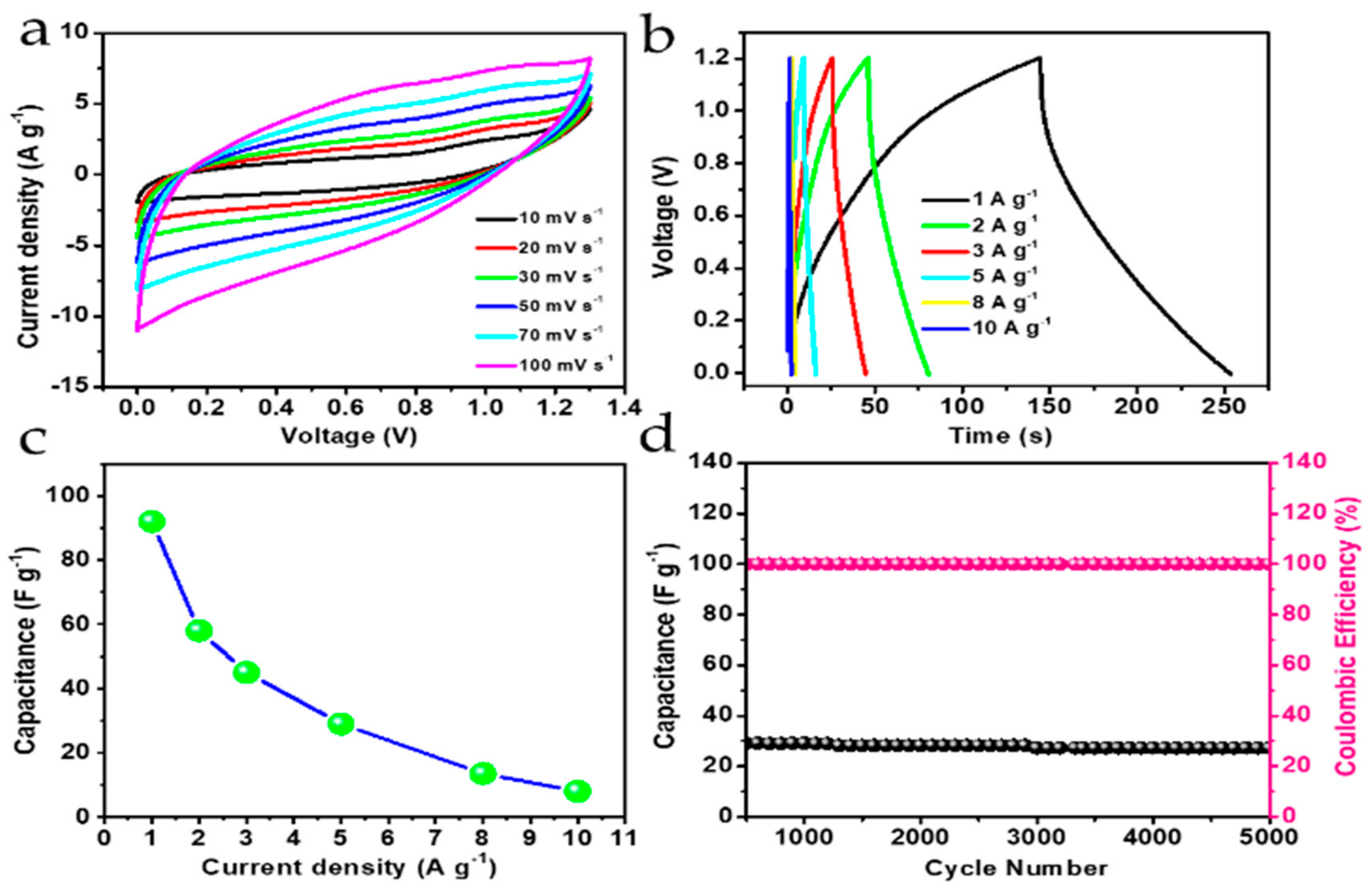
Another important electrochemical aspect of any electrode material is its cycling stability, which is an essential criterion for establishing its endurance before it can be employed in the ES devices. Figure 5e shows the long-term cycling stability of the ES electrode up to 10,000 cycles of GCD @ 5 A g−1 current density. Stable capacitance retention with almost 95% of its initial capacitance was achieved after cycling while securing a 99.5% of columbic efficiency, indicating the excellent kinetic reversibility of the electrode. The stability of Bi2O3-MnO2 energy storage properties after cycling are well attested by its CV, GCD, and EIS performance, which are presented in detail in Figure S8a–c of the supporting information. Comparing the electrochemical performance of the as-synthesized Bi2O3-MnO2 nanocomposite with literature data (Table 1), several unique features can be observed: (i) Better cycling stability compared to other bismuth oxide electrodes, and (ii) a higher working potential window with excellent ES properties. [23] Meanwhile the synthesis technique used is comparatively cheaper, easily scalable, and facile. These unique features of the Bi2O3-MnO2 electrode and its high energy storage performance could possibly be attributed to: (i) The fused nanoplatelet-like morphology with multiple interconnecting points allowing fast electron transport, (ii) good crystallinity with reduced electronic resistance, (iii) a mesoporous structure allowing better ionic/mass transportation, and (iv) Chemically and mechanically stable nanomaterial providing its long-term usability. Further, to realize the application potential of the Bi2O3-MnO2 ES electrode, a Bi2O3-MnO2//Bi2O3-MnO2 symmetric ES device was assembled and then subjected to CV and GCD measurements, as demonstrated in Figure 6a,b, respectively. The CV scanning performed from a low to high scan rate within a 0−1.3 V stable potential range confirmed the capacitive-type charge storage behavior of the symmetric ES device, which is almost similar to that of the individual Bi2O3-MnO2 in a three electrode configuration. While scanning, these curves retained their shapes under different scan rates, suggesting good reversibility of ion transport at the electrode/electrolyte interface. Charge-discharge measurements were carried out from low to high current density as shown in Figure 6b, to determine the real-time charge storage ability of the device. As can be seen from the GCD curves, there is a slight deviation from its linearity compared to the single-electrode GCD curves. We believe that this increased resistance observed in the charge−discharge performance is possibly due to inter-electrode separation.
Furthermore, the capacitance retention with increasing current density up to 10 A g−1 (in Figure 6c) evidences the rate capability of the symmetric device. The SC values calculated at 1 A g−1 and 10 A g−1 reached 92 F g−1 and 8 F g−1, respectively. Long-term cycling stability is also a crucial parameter to assess the practical application of a symmetric ES device. Figure 6d presents cycling stability plot of the device, where, GCD cycling measurement was performed at 5 A g−1, showing only 4% loss over 5000 cycles, with 99% of columbic efficiency.
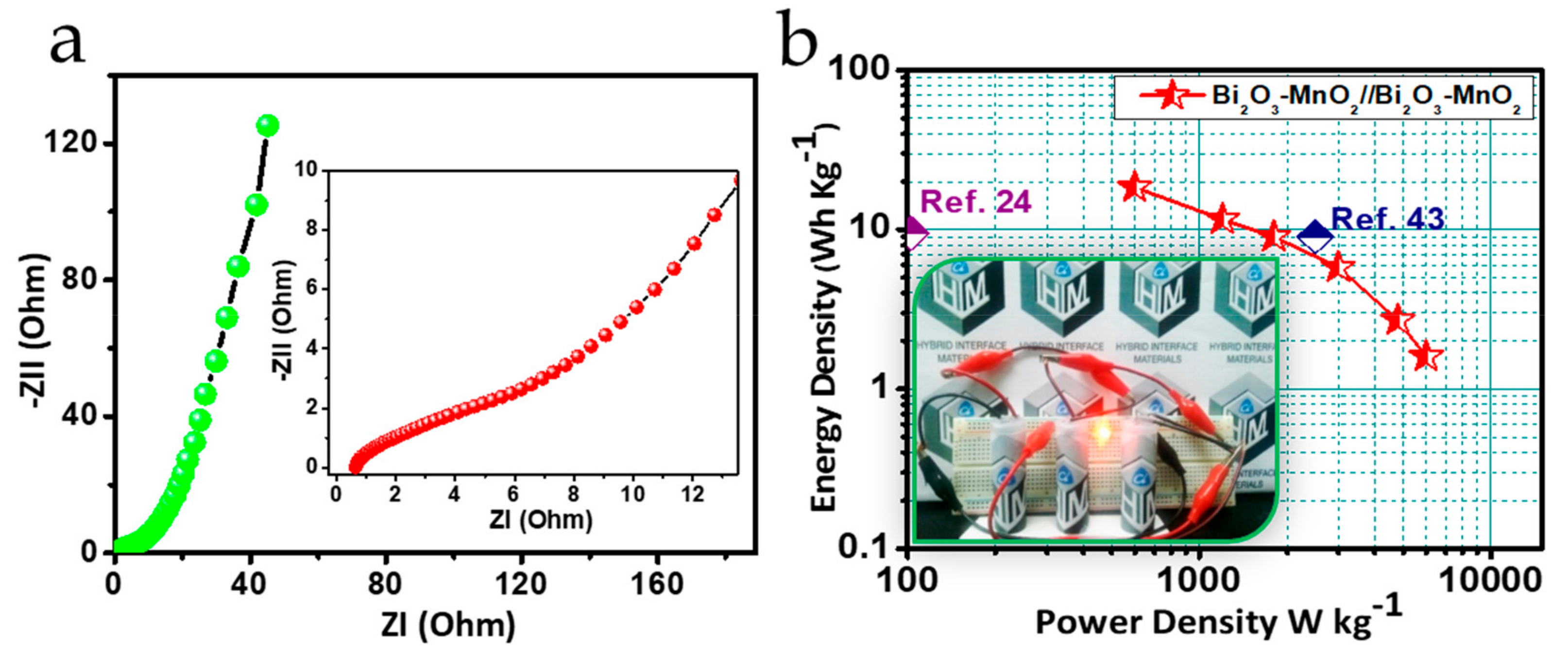
To further understand the electrochemical performance of the device, EIS measurements were conducted. As can be seen from the Nyquist plot in the high-frequency region (Figure 7a), the Z’-intercept on the x-axis indicates a value of 0.6 Ω for the series resistance, indicating a favorable power density for the device. In the same figure, from the inserted magnified portion of the Nyquist plot, the charge transfer resistance can be estimated to be 3 Ω based on the curvature diameter, suggesting benign transport properties at the electrode/electrolyte interface, endowing substantial charge storage ability to the device. Also, the slope of the straight line in the high frequency region being greater than 45° is a clear indication of surface-controlled device performance. Finally, Figure 7b shows the Ragone plot for the Bi2O3-MnO2 symmetric device, where an energy density of about 18.4 W h Kg−1 obtained at a power density of 600 W kg−1 is higher than the previously reported device based on bismuth manganese composite [24,43], corroborating the synergistic influence of Bi2O3 and MnO2 in the performance of symmetric Bi2O3-MnO2 ES device. A single LED was also powered for several minutes using three symmetric Bi2O3-MnO2 ES devices connected in series, as shown in Figure 7b (inset), giving us confidence in the possibility of commercial utilization of this material.

4. Conclusions

In summary, our work provides an easily scalable, low-cost, and environment friendly solid-state chemical synthesis approach to prepare a Bi2O3-MnO2 nanocomposite electrode material for high-performance ES applications. Due to the excellent synergy of Bi2O3 and MnO2, the polycrystalline and mesoporous Bi2O3-MnO2 nanocomposite electrode was able to deliver 161 F g−1 specific capacitance @ 1 A g−1. Moreover, the nanocomposite showed superior rate capability up to 10A g−1 and cycling retention of nearly 95% for cycling over 10,000 charge-discharge cycles. Further, the as-assembled Bi2O3-MnO2 // Bi2O3-MnO2 symmetric device demonstrated 18.4 Wh kg−1 energy density @ 600 W kg−1 power density and rate capability up to 10 A g−1. Later on, when the device was cycled 5000 times, it still retained nearly 96% of its initial energy density. Our work inspires the preparation of other metal oxide nanocomposites using a solid-state synthesis route for their application as high-performance ES electrode materials.

Supplementary Materials

The following are available online at https://www.mdpi.com/1996-1073/12/17/3320/s1, Figure S1: SEM image of Bi2O3 nanostructure (a) Low magnification and (b) High Magnification, Figure S2. N2-adsorption/desorption isotherms including BJH pore size distribution curve (inset) for Bi2O3-MnO2 nanocomposite powder, Figure S3. Powder XRD for Bi2O3-MnO2 nanocomposite before annealing, Figure S4. (a) CV and (b) GCD performance of Bi2O3 ES electrode, Figure S5. CV performance comparison of Bi2O3, MnO2, and Bi2O3-MnO2 ES electrode, Figure S6. CV performance comparison of Bi2O3-MnO2 ES electrode and bare Ni-foam, Figure S7. (a) CV and (b) GCD performance of MnO2 ES-electrode in 1M NaoH electrolyte, Figure S8. (a) CV (b) GCD and (c) EIS performance of Bi2O3-MnO2 ES electrode after cycling.

Author Contributions

Conceptualization, Methodology and Review by R.S.M., Electrochemical Measurement assistance by N.M.S., Characterization of Materials, Review and English Revision by J.M.Y., Experiments, Manuscript writing, Data presentation and Review by S.S., Data analysis, its Presentation Assistance, and Review by R.K.S., Formal Analysis and Supervision by K.H.K.

Funding

This research received no external funding.

Acknowledgments

We gratefully acknowledge the support of this work by the Global Frontier Program through the Global Frontier Hybrid Interface Materials (GFHIM) of the National Research Foundation of Korea (NRF) funded by the Ministry of Science, ICT & Future Planning (2013M3A6B1078874). The authors are very grateful to the members of the National Core Research Centre (NCRC) for their excellent experimental assistance.

Conflicts of Interest

The authors declare no conflict of interest.

References

  1. Hall, P.J.; Bain, E.J. Energy-storage technologies and electricity generation. Energy Policy 2008, 36, 4352–4355. [Google Scholar] [CrossRef] [Green Version]
  2. Kyriakopoulos, G.L.; Arabatzis, G. Electrical energy storage systems in electricity generation: Energy policies, innovative technologies, and regulatory regimes. Renew. Sust. Energ. Rev. 2016, 56, 1044–1067. [Google Scholar] [CrossRef]
  3. Vlad, A.; Singh, N.; Rolland, J.; Melinte, S.; Ajayan, P.M.; Gohy, J.F. Hybrid supercapacitor-battery materials for fast electrochemical charge storage. Sci. Rep. 2014, 4, 4315. [Google Scholar] [CrossRef] [Green Version]
  4. Kötz, R.; Müller, S.; Bärtschi, M.; Schnyder, B.; Dietrich, P.; Büchi, F.; Tsukada, A.; Scherer, G.; Rodatz, P.; Garcia, O. Supercapacitors for peak-power demand in fuel-cell-driven cars. Electrochem. Soc. 2001, 21, 564–575. [Google Scholar]
  5. Chen, G.Z. Supercapacitor and supercapattery as emerging electrochemical energy stores. Int. Mater. Rev. 2017, 62, 173–202. [Google Scholar] [CrossRef]
  6. Cherusseri, J.; Kar, K.K. Hierarchically mesoporous carbon nanopetal based electrodes for flexible supercapacitors with super-long cyclic stability. J. Mater. Chem. A 2015, 3, 21586–21598. [Google Scholar] [CrossRef]
  7. Aravinda, L.; Nagaraja, K.; Nagaraja, H.; Bhat, K.U.; Bhat, B.R. ZnO/carbon nanotube nanocomposite for high energy density supercapacitors. Electrochim. Acta 2013, 95, 119–124. [Google Scholar] [CrossRef]
  8. Fan, Z.; Yan, J.; Zhi, L.; Zhang, Q.; Wei, T.; Feng, J.; Zhang, M.; Qian, W.; Wei, F. A three-dimensional carbon nanotube/graphene sandwich and its application as electrode in supercapacitors. Adv. Mater. 2010, 22, 3723–3728. [Google Scholar] [CrossRef]
  9. Wu, H.; Xu, C.; Xu, J.; Lu, L.; Fan, Z.; Chen, X.; Song, Y.; Li, D. Enhanced supercapacitance in anodic TiO2 nanotube films by hydrogen plasma treatment. Nanotechnology 2013, 24, 455401. [Google Scholar] [CrossRef]
  10. Dou, S.; Tao, L.; Wang, R.; El Hankari, S.; Chen, R.; Wang, S. Plasma-Assisted Synthesis and Surface Modification of Electrode Materials for Renewable Energy. Adv. Mater. 2018, 30, 1705850. [Google Scholar] [CrossRef]
  11. Wei, T.Y.; Chen, C.H.; Chien, H.C.; Lu, S.Y.; Hu, C.C. A cost-effective supercapacitor material of ultrahigh specific capacitances: Spinel nickel cobaltite aerogels from an epoxide-driven sol–gel process. Adv. Mater. 2010, 22, 347–351. [Google Scholar] [CrossRef] [PubMed]
  12. Xu, Y.; Wang, L.; Cao, P.; Cai, C.; Fu, Y.; Ma, X. Mesoporous composite nickel cobalt oxide/graphene oxide synthesized via a template-assistant co-precipitation route as electrode material for supercapacitors. J. Power Sources 2016, 306, 742–752. [Google Scholar] [CrossRef]
  13. Li, L.; Guo, X.; Hao, F.; Zhang, X.; Chen, J. Solid-state grinding/low-temperature calcining synthesis of carbon coated MnO2 nanorods and their electrochemical capacitive property. New J. Chem. 2015, 39, 4731–4736. [Google Scholar] [CrossRef]
  14. Patil, S.A.; Shinde, D.V.; Patil, D.V.; Tehare, K.K.; Jadhav, V.V.; Lee, J.K.; Mane, R.S.; Shrestha, N.K.; Han, S.-H. A simple, room temperature, solid-state synthesis route for metal oxide nanostructures. J. Mater. Chem. A 2014, 2, 13519–13526. [Google Scholar] [CrossRef]
  15. Zhang, L.; Ou, M.; Yao, H.; Li, Z.; Qu, D.; Liu, F.; Wang, J.; Wang, J.; Li, Z. Enhanced supercapacitive performance of graphite-like C3N4 assembled with NiAl-layered double hydroxide. Electrochim. Acta 2015, 186, 292–301. [Google Scholar] [CrossRef]
  16. Chen, H.; Hu, L.; Yan, Y.; Che, R.; Chen, M.; Wu, L. One-Step Fabrication of Ultrathin Porous Nickel Hydroxide-Manganese Dioxide Hybrid Nanosheets for Supercapacitor Electrodes with Excellent Capacitive Performance. Adv. Energy Mater. 2013, 3, 1636–1646. [Google Scholar] [CrossRef]
  17. Xu, H.; Hu, X.; Yang, H.; Sun, Y.; Hu, C.; Huang, Y. Flexible Asymmetric Micro-Supercapacitors Based on Bi2O3 and MnO2 Nanoflowers: Larger Areal Mass Promises Higher Energy Density. Adv. Energy Mater. 2015, 5, 1401882. [Google Scholar] [CrossRef]
  18. Li, J.; Wu, Q.; Zan, G. A High-Performance Supercapacitor with Well-Dispersed Bi2O3 Nanospheres and Active-Carbon Electrodes. Eur. J. Inorg. Chem. 2015, 2015, 5751–5756. [Google Scholar] [CrossRef]
  19. Feng, X.Q.; Li, Y.H.; Chen, G.S.; Liu, Z.; Ning, X.H.; Hu, A.P.; Tang, Q.L.; Chen, X.H. Free-standing MnO2/nitrogen-doped graphene paper hybrids as binder-free electrode for supercapacitor applications. Mater. Lett. 2018, 231, 114–118. [Google Scholar] [CrossRef]
  20. Lin, L.Y.; Huang, M.C.; Ning, M.L.; Wu, K.W.; Li, H.W.; Hussain, S.; Zhao, S.Q. Facile ordered ZnCo2O4@MnO2 nanosheet arrays for superior-performance supercapacitor electrode. Solid State Sci. 2018, 84, 51–56. [Google Scholar] [CrossRef]
  21. Liu, P.B.; Zhu, Y.D.; Gao, X.G.; Huang, Y.; Wang, Y.; Qin, S.Y.; Zhang, Y.Q. Rational construction of bowl-like MnO2 nanosheets with excellent electrochemical performance for supercapacitor electrodes. Chem. Eng. J. 2018, 350, 79–88. [Google Scholar] [CrossRef]
  22. Huang, Z.-H.; Song, Y.; Feng, D.-Y.; Sun, Z.; Sun, X.; Liu, X.-X. High mass loading MnO2 with hierarchical nanostructures for supercapacitors. ACS Nano 2018, 12, 3557–3567. [Google Scholar] [CrossRef] [PubMed]
  23. Ma, J.; Zhu, S.; Shan, Q.; Liu, S.; Zhang, Y.; Dong, F.; Liu, H. Facile synthesis of flower-like (BiO)2CO3@ MnO2 and Bi2O3@ MnO2 nanocomposites for supercapacitors. Electrochim. Acta 2015, 168, 97–103. [Google Scholar] [CrossRef]
  24. Ng, C.H.; Lim, H.N.; Hayase, S.; Zainal, Z.; Shafie, S.; Huang, N.M. Effects of temperature on electrochemical properties of bismuth oxide/manganese oxide pseudocapacitor. Ind. Eng. Chem. Res. 2018, 57, 2146–2154. [Google Scholar] [CrossRef]
  25. Singh, S.; Shinde, N.M.; Xia, Q.X.; Gopi, C.; Yun, J.M.; Mane, R.S.; Kim, K.H. Tailoring the morphology followed by the electrochemical performance of NiMn-LDH nanosheet arrays through controlled Co-doping for high-energy and power asymmetric supercapacitors. Dalton Trans. 2017, 46, 12876–12883. [Google Scholar] [CrossRef]
  26. Shinde, N.M.; Xia, Q.X.; Yun, J.M.; Singh, S.; Mane, R.S.; Kim, K.H. A binder-free wet chemical synthesis approach to decorate nanoflowers of bismuth oxide on Ni-foam for fabricating laboratory scale potential pencil-type asymmetric supercapacitor device. Dalton Trans. 2017, 46, 6601–6611. [Google Scholar] [CrossRef]
  27. Zhang, L.; Ghimire, P.; Phuriragpitikhon, J.; Jiang, B.; Gonçalves, A.A.; Jaroniec, M. Facile formation of metallic bismuth/bismuth oxide heterojunction on porous carbon with enhanced photocatalytic activity. J. Colloid Interface Sci. 2018, 513, 82–91. [Google Scholar] [CrossRef]
  28. Nesbitt, H.W.; Banerjee, D. Interpretation of XPS Mn(2p) spectra of Mn oxyhydroxides and constraints on the mechanism of MnO2 precipitation. Am. Miner. 1998, 83, 305–315. [Google Scholar] [CrossRef]
  29. Zampieri, G.; Abbate, M.; Prado, F.; Caneiro, A. Mn-2p XPS spectra of differently hole-doped Mn perovskites. Solid State Commun. 2002, 123, 81–85. [Google Scholar] [CrossRef]
  30. John, R.E.; Chandran, A.; Thomas, M.; Jose, J.; George, K. Surface-defect induced modifications in the optical properties of α-MnO2 nanorods. Appl. Surf. Sci. 2016, 367, 43–51. [Google Scholar] [CrossRef]
  31. Andreeva, A.Y.; Sukhikh, T.S.; Kozlova, S.G.; Konchenko, S.N. Exchange interactions and XPS O1s spectra in polynuclear lanthanide complexes with dibenzoylmethanide and 4-hydroxy-2,1,3-benzothiadiazole. J. Mol. Struct. 2018, 1166, 190–194. [Google Scholar] [CrossRef]
  32. Kotsis, K.; Staemmler, V. Ab initio calculations of the O1s XPS spectra of ZnO and Zn oxo compounds. Phys. Chem. Chem. Phys. 2006, 8, 1490–1498. [Google Scholar] [CrossRef] [PubMed]
  33. Nanba, T.; Miura, Y.; Sakida, S. Consideration on the correlation between basicity of oxide glasses and O1s chemical shift in XPS. J. Ceram. Soc. Jpn. 2005, 113, 44–50. [Google Scholar] [CrossRef]
  34. Sopha, H.; Spotz, Z.; Michalicka, J.; Hromadko, L.; Bulanek, R.; Wagner, T.; Macak, J.M. Bismuth Oxychloride Nanoplatelets by Breakdown Anodization. ChemElectroChem 2019, 6, 336–341. [Google Scholar] [CrossRef] [PubMed]
  35. Kitchaev, D.A.; Peng, H.W.; Liu, Y.; Sun, J.W.; Perdew, J.P.; Ceder, G. Energetics of MnO2 polymorphs in density functional theory. Phys. Rev. B 2016, 93, 5. [Google Scholar] [CrossRef]
  36. Manthiram, A.; Murugan, A.V.; Sarkar, A.; Muraliganth, T. Nanostructured electrode materials for electrochemical energy storage and conversion. Energy Environ. Sci. 2008, 1, 621–638. [Google Scholar] [CrossRef]
  37. Gujar, T.P.; Shinde, V.R.; Lokhande, C.D.; Mane, R.S.; Han, S.H. Bismuth oxide thin films prepared by chemical bath deposition (CBD) method: Annealing effect. Appl. Surf. Sci. 2005, 250, 161–167. [Google Scholar] [CrossRef]
  38. Yu, X.; Yun, S.; Yeon, J.S.; Bhattacharya, P.; Wang, L.; Lee, S.W.; Hu, X.; Park, H.S. Emergent Pseudocapacitance of 2D Nanomaterials. Adv. Energy Mater. 2018, 8, 1702930. [Google Scholar] [CrossRef]
  39. Ghodbane, O.; Ataherian, F.; Wu, N.-L.; Favier, F. In situ crystallographic investigations of charge storage mechanisms in MnO2-based electrochemical capacitors. J. Power Sources 2012, 206, 454–462. [Google Scholar] [CrossRef]
  40. Yuan, D.; Zeng, J.; Kristian, N.; Wang, Y.; Wang, X. Bi2O3 deposited on highly ordered mesoporous carbon for supercapacitors. Electrochem. Commun. 2009, 11, 313–317. [Google Scholar] [CrossRef]
  41. Wang, S.; Jin, C.; Qian, W. Bi2O3 with activated carbon composite as a supercapacitor electrode. J. Alloy. Compd. 2014, 615, 12–17. [Google Scholar] [CrossRef]
  42. Liu, Y.; Zhitomirsky, I. Electrochemical supercapacitor based on multiferroic BiMn2O5. J. Power Sources 2015, 284, 377–382. [Google Scholar] [CrossRef]
  43. Yang, W.-D.; Lin, Y.-J. Preparation of rGO/Bi2O3 composites by hydrothermal synthesis for supercapacitor electrode. J. Electr. Eng. 2019, 70, 101–106. [Google Scholar]
  44. Ciszewski, M.; Mianowski, A.; Szatkowski, P.; Nawrat, G.; Adamek, J. Reduced graphene oxide–bismuth oxide composite as electrode material for supercapacitors. Ionics 2015, 21, 557–563. [Google Scholar] [CrossRef]
  45. Sundriyal, P.; Bhattacharya, S. Scalable Micro-fabrication of Flexible, Solid-State, Inexpensive, and High-Performance Planar Micro-supercapacitors through Inkjet Printing. ACS Appl. Energy Mater. 2019, 2, 1876–1890. [Google Scholar] [CrossRef]
  46. Yu, T.; Li, Z.; Chen, S.; Ding, Y.; Chen, W.; Liu, X.; Huang, Y.; Kong, F. Facile synthesis of flowerlike Bi2MoO6 hollow microspheres for high-performance supercapacitors. ACS Sustain. Chem. Eng. 2018, 6, 7355–7361. [Google Scholar] [CrossRef]
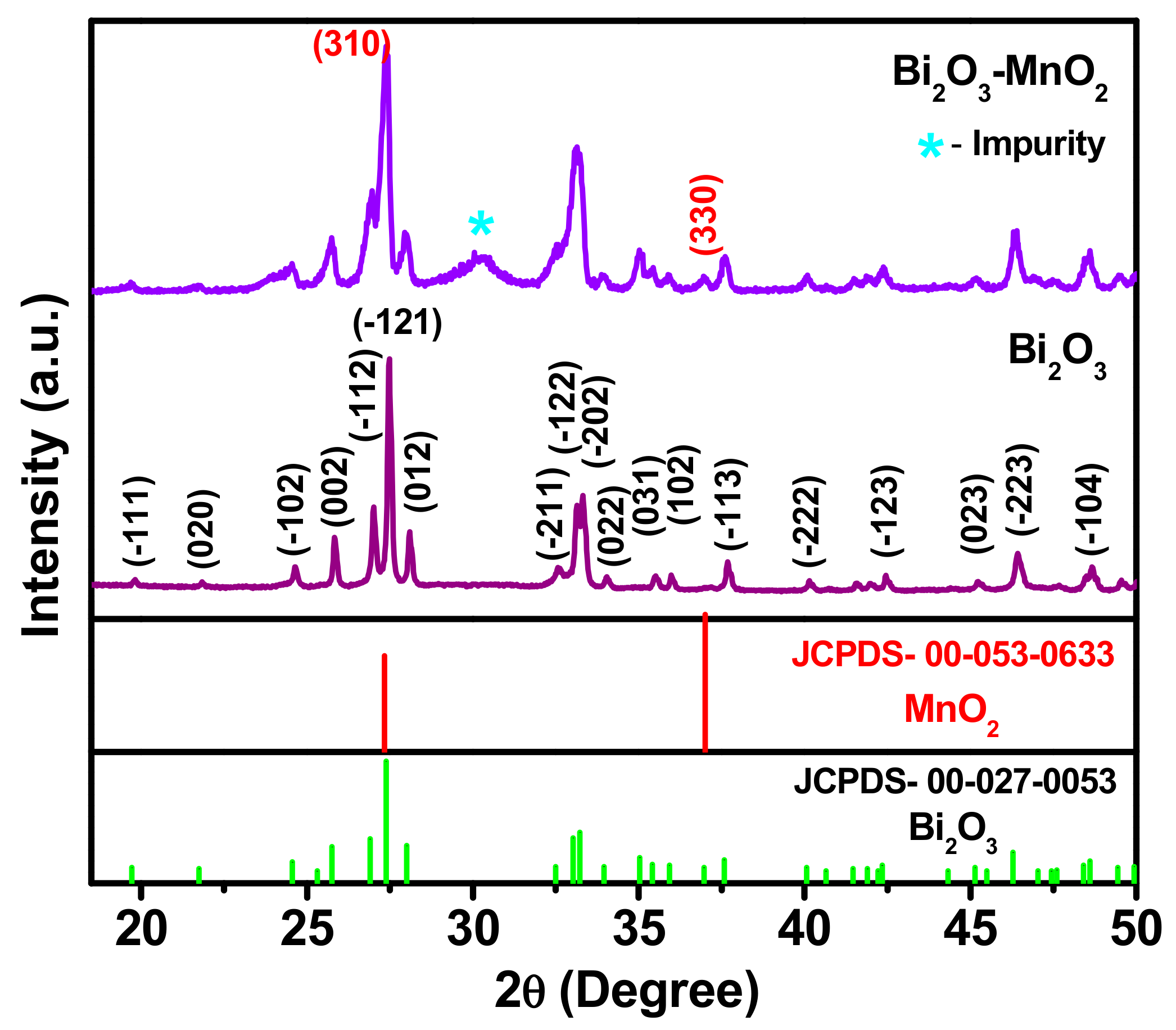
Figure 1. The X-ray diffraction (XRD) patterns of Bi2O3 and Bi2O3-MnO2 nanocomposites.
Energies 12 03320 g001
Figure 2. X-ray photoelectron spectroscopy (XPS) analysis, (a) full scan spectrum of Bi2O3-MnO2, (b) narrow scan of Bi 4f, (c) Mn 2p, and (d) O 1.
Energies 12 03320 g002
Figure 3. (a) Low-magnification field-emission scanning electron microscope (FE-SEM) image along with magnified image in the inset (a1), showing single faceted crystal. (b) Transmission electron microscopy (TEM) image and (c) high-resolution TEM (HRTEM) image from the marked square portion in Figure 3b. (d) high-angle annular dark field (HAADF) image. (eh) EDX mapping images confirming the presence of Bi, O, and Mn elements.
Energies 12 03320 g003
Figure 4. (a) Cyclic voltammetry (CV) and (b) galvanostatic charge–discharge (GCD) comparison of Bi2O3 and Bi2O3-MnO2 ES electrodes.
Energies 12 03320 g004
Figure 5. (a) CV, (b) GCD, (c) electrochemical impedance spectroscopy (EIS), (d) rate capability, and (e) cycling test results from the Bi2O3-MnO2 ES electrode.
Energies 12 03320 g005
Figure 6. (a) CV, (b) GCD, (c) Rate capability, and (d) cycling performance of the Bi2O3-MnO2 symmetric device.
Energies 12 03320 g006
Figure 7. (a) Nyquist plot for Bi2O3-MnO2 ES electrode (inset—magnified plot in the high frequency range) and (b) Ragone plot for the symmetric device assembly (inset—demonstrating LED lighting).
Energies 12 03320 g007
Table 1. A summary of electrochemical performance for Bi2O3 based composite material.
Sl. No.MaterialsSpecific CapacitanceElectrolyteVoltage Difference (in V)Cycling Stability
(Specific Capacitance Retention)
Ref.
1Bi2O3/HOMC232 F g−1 @ 5 mV s−16 M KOH1.0 V 70% after 1000 cycles[40]
2AC–Bi2O3 composite332.6 F g−1 @1 A g−16 M KOH1.0 V60% after 1000 cycles[41]
3BiMn2O5- MWCNT6.0 F cm−2 @ 2 mV s−10.5 M Na2SO41.0 V90% after 1000 cycles[42]
4rGO-Bi2O3 composite216 F g−1 at 1 A g−11 M KOH1.0 VNot mentioned[43]
5RGO-Bi2O3 composite94 F g−1 @ 0.2 A g−16 M KOH1.0 V90% after 3000 cycles[44]
6AC-Bi2O30.5127 F cm−26 M KOH0.9 V92.2% after 20,000 cycles[45]
7Bi2MoO6182 F g−1 @ 1 A g−13 M KOH0.5 V 80% after 3000 cycles[46]
8Bi2O3@MnO293.1 F g−1 @ 1 A g−11 M Na2SO41 V112% after 1000 cycles[23]
9Bi2O3/MnO279.4 F g−1 @ 1 A g−11 M Na2SO41.0 V95% after 1000 cycles[24]
10Bi2O3-MnO2161 F g−1 @ 1 A g−11 M NaOH1.3 (GCD)95% after 10,000 cyclesThis Work