Article

Modeling and Control of a Novel Hybrid Power Quality Compensation System for 25-kV Electrified Railway

1
National Rail Transportation Electrification and Automation Engineering Technology Research Center, Chengdu 611756, China
2
School of Electrical Engineering, Southwest Jiaotong University, Chengdu 611756, China
*
Author to whom correspondence should be addressed.
Energies 2019, 12(17), 3303; https://doi.org/10.3390/en12173303
Submission received: 25 July 2019 / Revised: 22 August 2019 / Accepted: 26 August 2019 / Published: 27 August 2019
(This article belongs to the Special Issue HVDC/FACTS for Grid Services in Electric Power Systems)

Abstract

:
The severe power quality problems aroused by the single-phase 25-kV traction power supply system (TPSS), especially for the voltage unbalance (VU) and high-frequency harmonic resonance, have attracted increasing attention nowadays. In this paper, a novel hybrid power quality compensation system, including a power flow controller (PFC) and thyristor-controlled L and C-type filter (TCL-CTF), is proposed. The PFC can be used for VU compensation, and the TCL-CTF can be designed to filter out harmonics as well as compensate reactive power. Furthermore, an optimized compensation strategy is proposed, and the power quality of the TPSS can meet the requirements of the technology standard. Compared with the conventional scheme, the compensation capacity of the PFC can be reduced by 12%, as well as the cost. Finally, the effectiveness of the proposed system is verified by the simulation and experimental results.

1. Introduction

The Chinese government is rapidly constructing massive electrical railways to promote economic prosperity [1,2], which are mainly represented by their high speed and heavy load. According to the government’s report [3], the railway mileage will exceed 150,000 km, including 30,000 km high-speed railway, and the proportion of electrified railway will rise to 70% by 2020. As a result, the serious power quality problem aroused by the single-phase 25-kV traction power supply system (TPSS) has drawn increasing attention [4,5], especially for the voltage unbalance (VU) and the high-order harmonic problem in the weak power grid.
FACTS technology has increasingly drawn wide attention regarding the power quality of the government [6,7]. The power flow controller (PFC) scheme has been adopted to the TPSS [8], for example, by way of the railway static power conditioner (RPC) and co-phase TPSS. Mochinaga proposed the RPC [9]; different control strategies and structures have also been proposed [10,11,12]. On the other hand, Li proposed the co-phase TPSS configuration [13], which was applied to engineering in 2011 [14]; various other structures have also been proposed [15,16,17]. Compared with the co-phase TPSS, the apparent drawback of RPC is that it cannot eliminate the neutral zones. The super slope region—such as the length of the slope—has risen to 70 km in the Sichuan–Tibet railway, which will cause serious speed losses for electric multiple units (EMUs) and energy loss for the TPSS. Thus, the co-phase TPSS is a trend for the next-generation TPSS. However, the high-order harmonic resonance problem and the investment cost of high voltage and kVA power electronic devices are still obstructing its application in the TPSS.
The alternating current/direct current/alternating current (AC/DC/AC) traction converters are widely adopted to CRHs series of EMUs, and the HXD series of AC electric locomotives benefit from their excellent control performance and high power factor (PF). Nevertheless, a series of harmonic resonance accidents have been aroused by the high-frequency harmonic in recent years, which interferes with the safety and efficient operation of the TPSS [18,19]. Note that the PFC used in the TPSS possesses poor performance on compensating harmonic [20]. The passive power filter (PPF) and active power compensation device are frequently used for solving this problem. Nevertheless, the PPF is more available in terms of the cost and reliability. In this regard, the C-type filter has drawn attention to the railway field in recent years, as it not only filters out the particular high-order harmonic region, but also compensates for the reactive power to improve system performance [21]. Unfortunately, the over-compensation caused by the fixed Var capacity of C-type filters leads to the PF deterioration; it is unaccepted that the railway operator will pay a high fine to the power grid. Hence, how to greatly offset harmonic as well as PF is the main challenge. Fortunately, the power semiconductor switches, such as the thyristor, metal-oxide-semiconductor field-effect transistor (MOSFET), and insulated gate bipolar transistor (IGBT), have been adopted to control the inductance to achieve the reactive power compensation since the 1960s; most of the time, the thyristor will be involved when handling high voltage and simple AC circuit [22]. Thus, a thyristor-controlled LC-coupling (TCLC) structure has been introduced to govern the distortion and PF of the three-phase load in the power grid [23]. Furthermore, the different structure has been proposed, which combines the TCLCs in series/parallel with the active power filters (APFs), such as the TCLC + APF in [24], and the static var compensator (SVC)/APF in [25]. In other words, a novel hybrid compensation structure combined with the PPF and TCL can be designed to handle the above problem in railways. However, the relevant research in the railway field still lacks study.
Alternatively, the PFC of the TPSS is initially designed to compensate for VU and PF problems. However, due to the fluctuation of the traction load, the instant power demand has attached to 50 MVA, whereas the normal power demand has arrived 20 MVA; the PFC cannot provide a satisfactory compensation performance if the actual demand exceeds the designed capacity. Moreover, the cost also should be considered; the cost of a PFC is about $60/kVA according to the cost study in [24]. Therefore, a high-efficiency PFC is required to design the hybrid compensation system. On the one hand, the different multilevel constructs of PFC have been presented in recent years, which can reduce the switching frequency, power loss, and harmonic distortion [17,26]. In [17], a cascaded H-bridge multilevel construct is used for the PFC device. In [27], a novel PFC with a modular multilevel converter (MMC) construct has been adopted to the railway. On the other hand, an optimized compensation technique compensating for the power quality of load to satisfy the national standard is introduced to reduce the rating kVA. In [16], a hybrid compensation is proposed to reduce the capacity of PFC in the TPSS. Furthermore, a clear relationship between the power quality standard and the reference current is established in [17]. However, the capacity of a PFC is associated with not only the reactive power compensation, but also the active power balance. Therefore, a feasible method is using the PPF + TCL to compensate for reactive power, as they cost just 1/12th of the PFC, using PFC to compensate for the VU. Simultaneously, the control strategy of PFC should be redesigned to fit this hybrid power quality compensation system.
The rest of this paper is structured as follows: Section 2 introduces the circuit configuration of the proposed system. Furthermore, the power flow is analyzed in Section 3. In Section 4, the control strategy is proposed. The parameters of the TCL-CTF are designed in Section 5. The effectiveness is testified by simulation and experiment in Section 6. Finally, the conclusions are reached in Section 7.

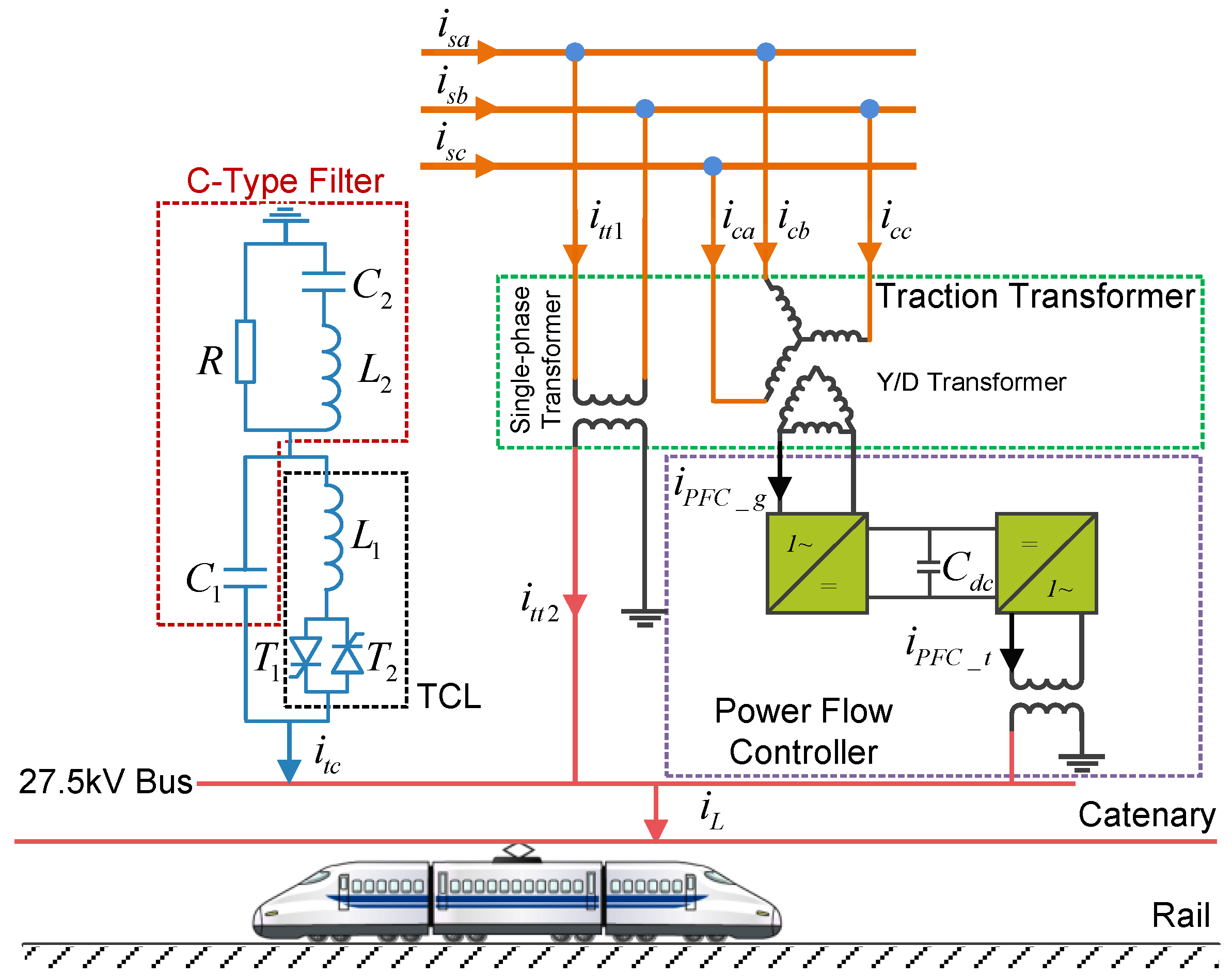
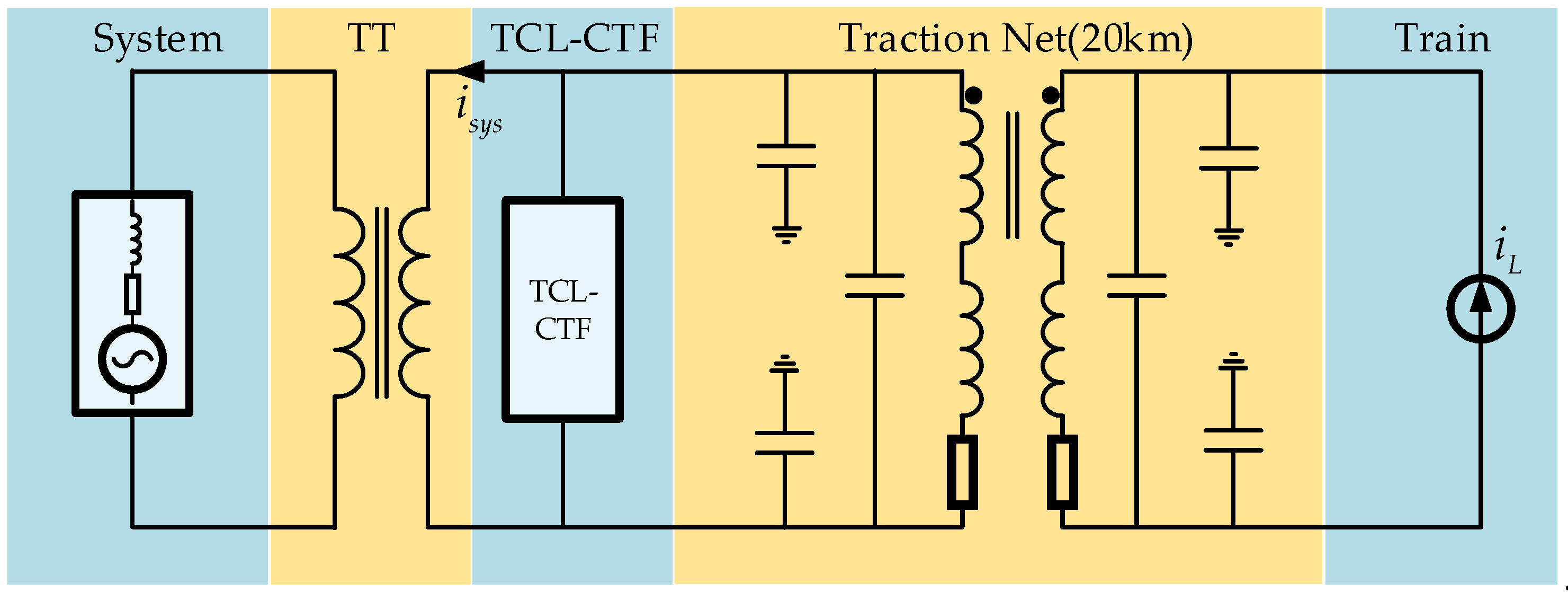
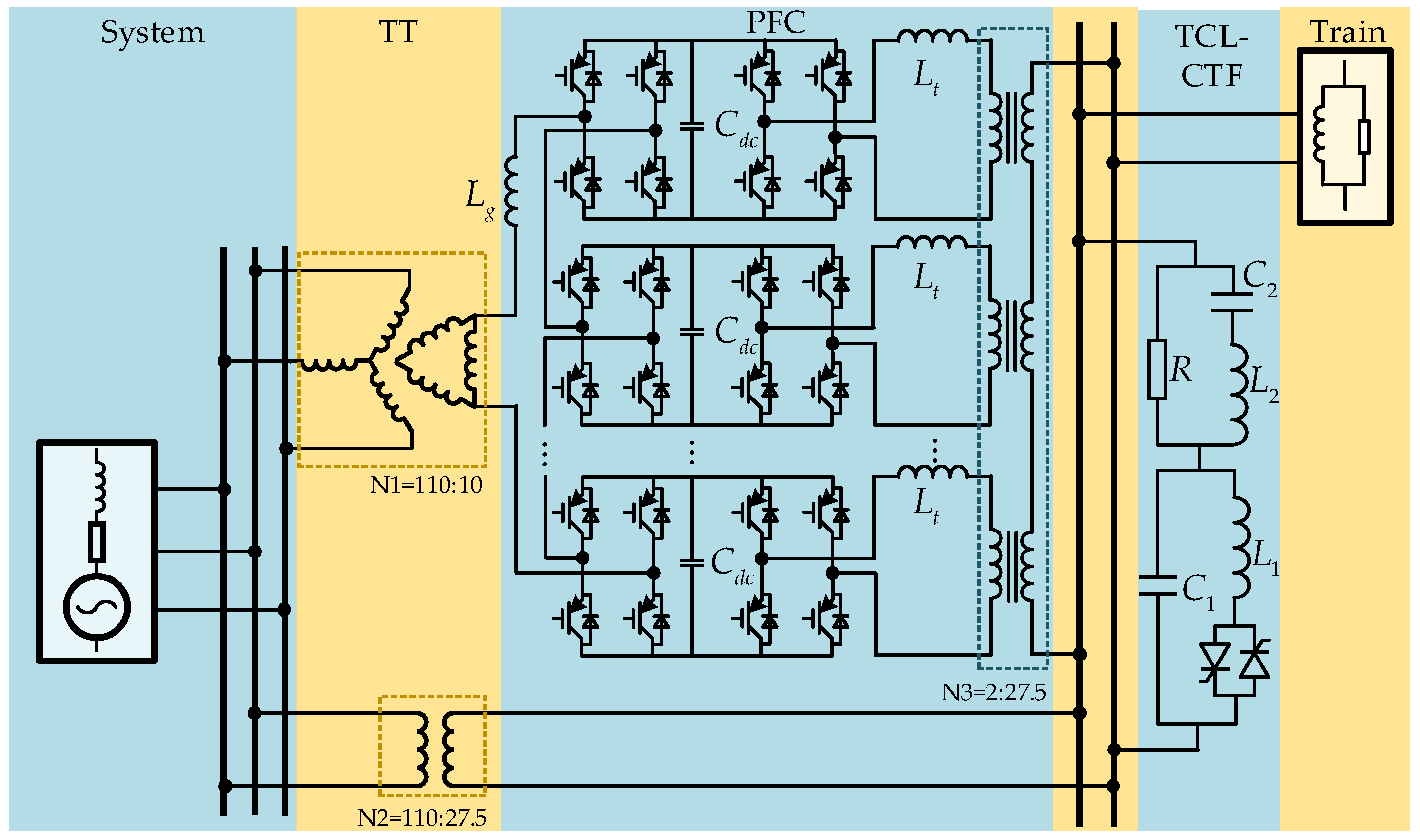
2. Circuit Configuration of the Proposed Hybrid Compensation System

Figure 1 shows the circuit configuration of the novel hybrid power quality compensation system for the TPSS. The proposed system consists of a TCL-CTF part, a traction transformer (TT) part, and a PFC part. The TCL-CTF part is composed of a thyristor-controlled reactor with an L 1 and C-type filter (CTF). The CTF is constituted by a capacitor C 1 , an auxiliary capacitor C 2 , a damping resistor R, and an inductor L 2 . The TCL and capacitor C 1 are responsible for supporting the fundamental reactive power to improve PF, which are controlled by triggering the firing angles α of the thyristor T 1 and T 2 . The CTF is designed to filter high-order harmonics. The TT is a balance transformer in which the negative-sequence current (NSC) is eliminated if the power of two ports is equal, which comprise a single-phase transformer (SPT) and a Y/D transformer. The PFC part consists of a DC-link capacitor C d c and two voltage source converters. It is employed to transfer the partial active power and selectively compensate for VU.
In Figure 1, i s x , and i c x are the source currents and the compensating currents where the x stands for phases a, b, and c in the following analysis. i t t 1 and i t t 2 are the primary and secondary side currents of the single-phase transformer, respectively. i g and i t are the grid and traction-side port currents of the PFC, respectively. i t c is the current of the TCL-CTF part.

3. Power Analysis of the Proposed Hybrid Compensation System

According to the research [28,29], there is some coupling power between the different components, not just the positive-sequence or negative-sequence power. Thus, the excited power calculation approach of load, based on the sequence component or vector method, could become invalid under the non-sinusoidal and asymmetrical conditions. To cope with this problem, the IEEE Standards Association (IEEE-SA) released IEEE Std. 1459 in 2010, which introduced the ‘effective’ value of voltage, current, and apparent power. Furthermore, the total effective apparent load power ( S L ) can be defined as:
S L 2 = S L 1 2 + S L h 2 = ( S L 1 + ) 2 + ( S L u 1 ) 2 + ( S L h ) 2
where S L 1 and S L h are the fundamental and harmonic-component of the load apparent power, respectively. S L 1 + and S L u 1 are fundamental positive-sequence and unbalanced component of the load apparent power, respectively.
Moreover, the fundamental positive-sequence component of the load apparent power ( S L 1 + ) can be divided into two terms: active power and reactive power.
( S L 1 + ) 2 = ( P L 1 + ) 2 + ( Q L 1 + ) 2
where P L 1 + and Q L 1 + are the load active power and load reactive power, respectively.
On the basis of Figure 1, the fundamental load active power ( P L 1 + ) comes from the single-phase transformer (SPT) and PFC branches.
( P L 1 + ) 2 = ( P S P T + ) 2 + ( P P F C + ) 2
where P S P T + and P P F C + are the active power through the SPT and PFC branches, respectively.
The fundamental load reactive power ( Q L 1 + ) is mainly supported by the TCL-CTF branch, and the rest is provided by the SPT and PFC branches. The Q L 1 + can be fully or partly compensated via the TCL-CTF.
( Q L 1 + ) 2 = ( Q S P T + ) 2 + ( Q P F C + ) 2 + ( K Q Q T C L C T F + ) 2
where Q S P T + , Q P F C + , and Q T C L - C T F + are the active power through the SPT, PFC, and TCL-CTF branches, respectively. K Q is a compensation coefficient, depending on the reference PF.
The fundamental load unbalanced component of the apparent power ( S L u 1 ) can be divided into the SPT and PFC branches.
( S L u 1 ) 2 = ( S L u 1 _ S P T ) 2 + ( k U S L u 1 _ P F C ) 2
where Q S P T + , Q P F C + , and Q T C L - C T F + are the active power through the SPT, PFC, and TCL-CTF branches, respectively. K U is a compensation coefficient, depending on the reference voltage unbalance factor (VUF).
In addition, the fundamental system unbalanced component of the apparent power ( S S u 1 ) that discharge into the power grid can be less than or equal to S L u 1 with the different compensation targets. After being compensated by PFC, the VU problem could be thoroughly eliminated if S L u 1 _ S P T = K U · S L u 1 _ P F C ; otherwise, the VU can be selectively compensated based on the national power quality standard.
( S S u 1 ) 2 ( S L u 1 _ S P T ) 2 ( k U S L u 1 _ P F C ) 2

4. Control Strategy of the Proposed Hybrid Compensation System

The proposed hybrid compensation system consists of a TCL-CTF part, a traction transformer (TT) part, and a PFC part. The TCL-CTF part is controlled to offset high-order harmonic ( S L h ) and selectively compensate the load reactive power ( Q L 1 + ) to improve the PF. The PFC part is used for transferring the partial active power and selectively compensating for the VU ( S L u 1 ). In the following, the control strategy will be discussed.

4.1. PFC Part Control

At present, the instantaneous power theory is widely adopted to detect the reactive, negative-sequence, and harmonic currents to provide an accurate reference for the power quality conditioner. Therefore, the positive and negative sequence components for each branch should be obtained before calculating the reference current, which can utilize the notch filter as [30]:
[ y z x + ] x = a , b , c = M 2 [ y z x ] x = a , b , c M 1 [ S π / 4 y z x ] x = a , b , c
[ y z x ] x = a , b , c = M 2 [ y z x ] x = a , b , c + M 1 [ S π / 4 y z x ] x = a , b , c
where S π / 4 stands for a π/4 phase-shift operator in the time domain, x stands for phases a, b, and c, y stands for current i or voltage u in the following analysis, z stands for the SPT part, PFC part, and so on. M 1 and M 2 are 3 × 3 matrices given by:
M 1 = 1 2 3 [ 0 1 1 1 0 1 1 1 0 ]
M 2 = 1 3 [ 1 0.5 0.5 0.5 1 0.5 0.5 0.5 1 ]
Then, the positive-sequence and negative-sequence component in the α-β frame are transformed from the a-b-c frame, which can be expressed as:
[ y z α + ( t ) y z β + ( t ) ] = [ 1 1 2 1 2 0 3 2 3 2 ] [ y z a + y z b + y z c + ]
[ y z α ( t ) y z β ( t ) ] = [ 1 1 2 1 2 0 3 2 3 2 ] [ y z a y z b y z c ]
Furthermore, based on the instantaneous power theory, the positive and negative-sequence components of instantaneous power can be obtained by Equations (13) and (14):
[ p z + q z + ] = [ u z α + u z β + u z β + u z α + ] [ i z α + i z β + ]
[ p z q z ] = [ u z β + u z α + u z α + u z β + ] [ i z α i z β ]
where p z + and q z + are positive-sequence components of the active and reactive instantaneous power, respectively. p z and q z are negative-sequence components of the active and reactive instantaneous power, respectively.
Under the non-sinusoidal and asymmetrical conditions, it should be noticed that the negative-sequence component of the instantaneous power calculated from Equations (13) and (14) includes two parts: DC composition and AC composition. To raise compensation performance, a low-pass filter (LPF) is added to obtain the DC component, due to AC composition including an almost harmonic element. Further, the unbalanced power ( p ¯ P F C and q ¯ P F C ) is partly compensated by a compensation coefficient K U .
[ i α _ P F C + i β _ P F C + ] = 1 ( u α _ P F C + ) 2 + ( u β _ P F C + ) 2 [ u α _ P F C + u β _ P F C + u β _ P F C + u α _ P F C + ] [ p ¯ P F C + q ¯ P F C + ]
[ i α _ P F C i β _ P F C ] = 1 ( u α _ P F C + ) 2 + ( u β _ P F C + ) 2 [ u β _ P F C + u α _ P F C + u α _ P F C + u β _ P F C + ] [ k U p ¯ P F C k U q ¯ P F C ]
The final reference currents of the grid side for PFC in a pq frame are transformed from the αβ frame:
[ i p _ g * i q _ g * ] = [ sin ω t cos ω t cos ω t sin ω t ] [ i α _ P F C + + i α _ P F C i β _ P F C + + i β _ P F C ]
where ω is a rated angular frequency of the power grid, which can be calculated from the PLL.
On the other hand, the operating characteristics of PFC can use the power balance principle to express as:
u T i p _ t t 2 + u g i p _ g = u T i p _ L
u T i q _ t t 2 + u g i q _ g = u T i q _ L
The reference currents of the traction side for PFC in a pq frame can be expressed as:
[ i p _ t * i q _ t * ] = N 1 ( [ i p _ L i q _ L ] [ i p _ t t 2 i q _ t t 2 ] )
where i p _ L and i q _ L are the load active and reactive current, respectively, which can be expressed as:
i p _ L = i L cos φ L , i q _ L = i L sin φ L ,
where φ L is the power factor angle of the traction load.
The compensation current of PFC tracks with its reference value i p _ g * , i q _ g * , and i p _ t * , while i q _ t * is calculated by above proposed method.
Furthermore, the capacity of PFC is calculated in the following equation based on [16,17]:
S P F C = S P F C _ g + S P F C _ t = U P F C _ g I P F C _ g + U P F C _ t I P F C _ t

4.2. TCL-CTF Part Control

The TCL achieves the dynamic adjustment of the inductive reactive power through changing the current’s amplitude, which is controlled by the firing delay angle of the thyristor. Afterward, it is combined with the fixed capacitive reactive power to compensate for the given PF. The equivalent fundamental impedance of the TCL and the capacitor C 1 can be expressed as:
X T C L C T F ( α ) = X T C L ( α ) X C 1 X T C L ( α ) X C 1
where X T C L ( α ) is the equivalent fundamental impendence of the TCL, which can be expressed as:
X T C L ( α ) = π 2 π 2 α + sin 2 α X L 1
where α is a firing angle of thyristor.
The compensating reactive power Q T C L - C T F + is associated with the equivalent fundamental impendence of the TCL-CTF, which can be expressed as shown in Equation (23):
Q T C L _ C T F + = U L 2 X T C L - C T F ( α )
In other words, the Q T C L - C T F + is coupled with the capacitor C 1 , reactor L 1 , and firing angle α. Thus, the relationships among these paraments are shown in Figure 2.
As can be observed in Figure 2a, the firing angle α increases from 90° to 180°, and the reactive power increases from 0 to 2 MVar with the C 1 = 8.4   μ F , which means that the compensating inductive reactive power is decreasing and controlled by the thyristor. Similarly, the reactive power is totally offset when L 1 = 1.2   H , α = 90°; then, the compensating capacitive reactive power increases when the firing angle α changes from 90° to 180° in Figure 2b.
To control the TCL, the equivalent fundamental susceptance of the TCL can be expressed as:
B T C L ( α ) = 1 X L 1 ( 2 2 α π + sin 2 α ) = 1 X L 1 δ sin δ π
where δ is a conduction angle, δ = 2 ( π - α ) .
However, the relationship between the B T C L ( α ) , δ and α is nonlinear, which means that it should add a linearization between the input and output of trigger pulse. In this paper, a look-up table (LUT) is adopted to address this obstruct [24].

4.3. Compensation Parameters Calculation between K U and K Q

4.3.1. Compensation Coefficient of VU K U

Associating with Equations (5) and (6), the compensation coefficient of VU ( K U ) can be expressed as:
K U = S L u 1 S S u 1 * S L u 1 _ P F C
where S L u 1 and S L u 1 _ P F C can be obtained as:
S L u 1 _ P F C = ( p ¯ P F C ) 2 + ( q ¯ P F C ) 2 , S L u 1 = ( p ¯ L ) 2 + ( q ¯ L ) 2
Simultaneously, the reference fundamental unbalanced component of the system apparent power ( S S u 1 * ) can be represented by a function containing VUF.
S S u 1 * = u s + i s + u s i s + + u s i s = S S 1 + ( CUF + VUF ) + S S 1 = S S 1 + [ Z T P S S + Z T P S S ( VUF + VUF 2 ) + VUF ]
where S S 1 + is the fundamental positive-sequence component of the system apparent power, while Z T P S S + and Z T P S S are the positive and negative sequence impedance of the TPSS.
The VUF values are dependent on the compensating target, which is restricted by the national power quality standard. The comparison of VU limits between the various countries is shown in Table 1.

4.3.2. Compensation Coefficient of PF K Q

According to the compensation target, the compensation coefficient of PF ( K Q ) can be expressed as:
K Q = S L + sin ( cos 1 P F * ) Q L +
where, PF* is an expected power factor after compensating.
Furthermore, the equivalent fundamental susceptance of the TCL can be obtained as:
B T C L ( α ) = Q L 1 * U L 2 = K Q Q L + Q C 1 U L 2

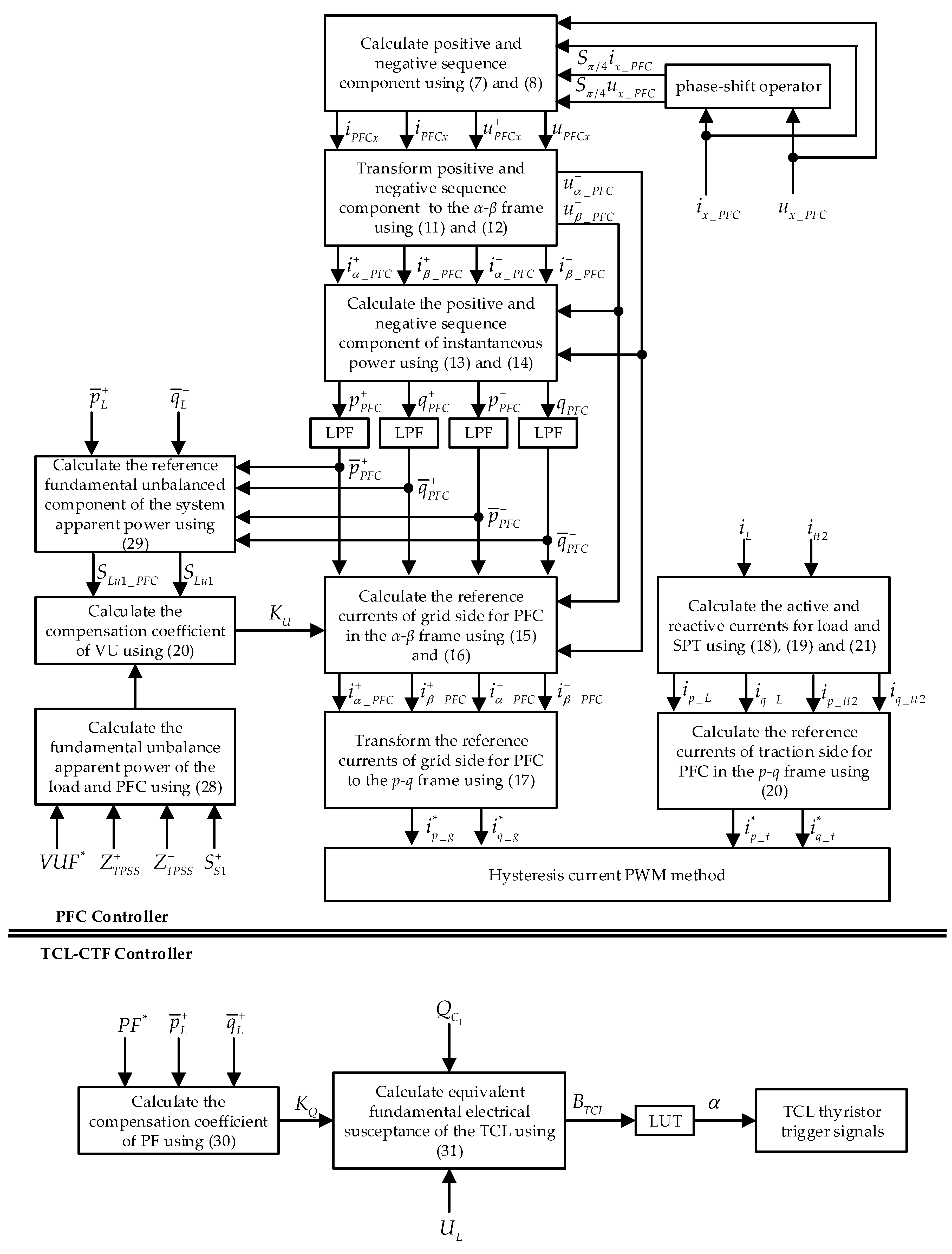
4.4. Control Block of the Proposed System

Figure 3 shows the overall control block with the proposed optimized compensation control approach. The control block includes two parts, which are the PFC controller and TCL-CTF controller. The compensation currents of the grid side for the PFC follow their reference currents, which controlled by K U to achieve the VU compensation target. Note that the K U is a dynastic variable that depends on the traction load power and system condition reflected by the impedance variation. Similarly, the trigger signals of the TCL can be generated based on its equivalent fundamental susceptance, which associates with the capacitive reactive power depending on the traction net voltage, traction load power, and PF compensation target.

5. Designing Parameters of the TCL-CTF

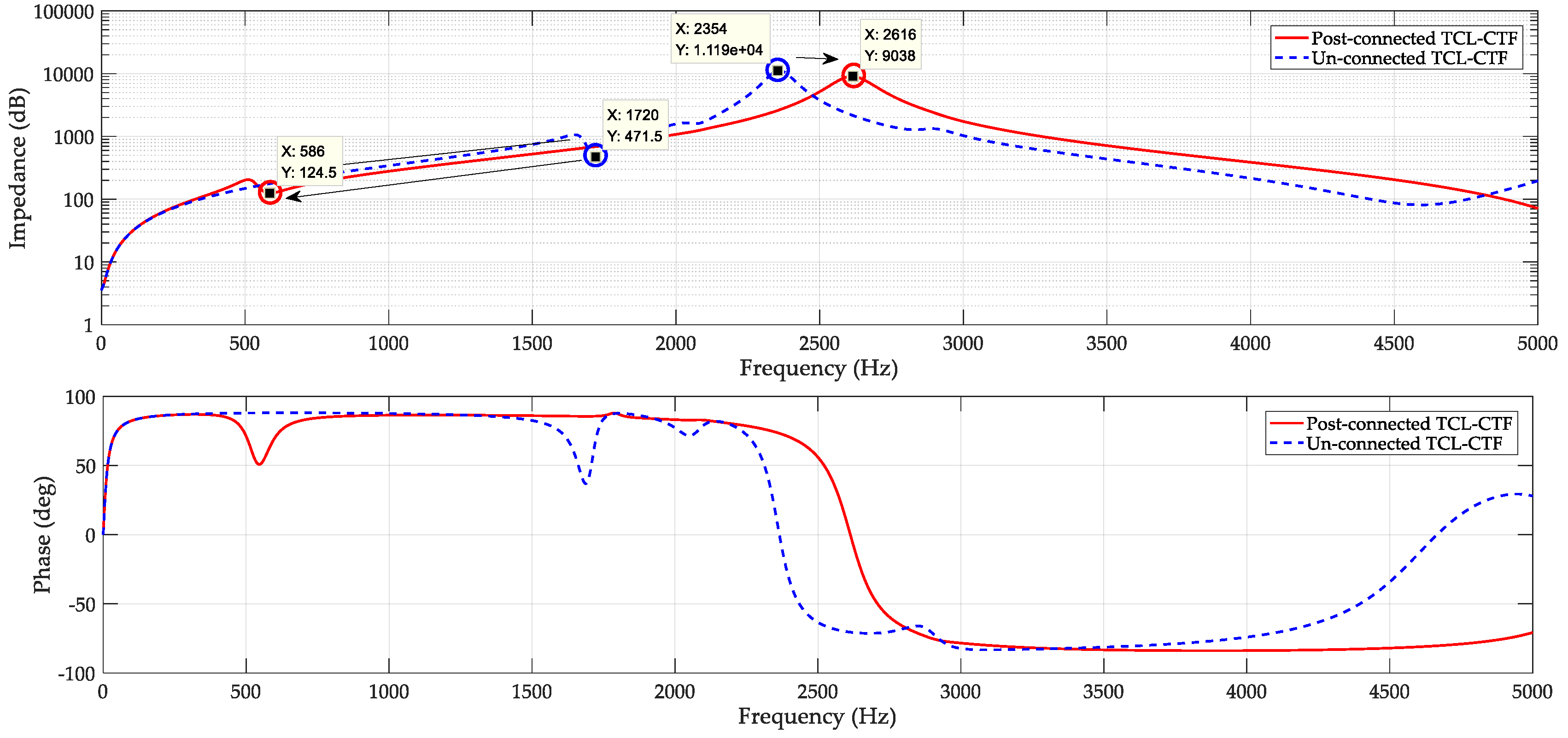
5.1. Resonance Damping Analysis

To research the characteristics of the proposed TCL-CTF, the equivalent impedance of the CTF is given as a function of the angular frequency and the parameters as follows:
Z T C L - C T F ( ω ) = j X C 1 ( ω ) / / j X L 1 ( ω ) + R / / [ j X L 2 ( ω ) j X C 2 ( ω ) ] = 1 j ω C 1 j ω L 1 1 j ω C 1 + j ω L 1 + ( j ω L 2 + 1 j ω C 2 ) R R + j ω L 2 + 1 j ω C 2 = j ω L 1 1 ω 2 L 1 C 1 + R ( 1 ω 2 L 2 C 2 ) 1 ω 2 L 2 C 2 + j ω R C 2
Figure 4 shows the impedance-frequency response of the TCL-CTF between the various parameters changing. In Figure 4a, when Q L 1 + varies from 1 Mvar to 3 MVar, the resonance point increase from 36 Hz to 63 Hz. Note that the resonance point at the fundamental frequency if Q L 1 + = Q C 1 + , which means that it is so dangerous that it should be avoided. However, the impedance characteristics of CTF maintain a stable status, the TCL-CTF obtains a minimum impedance when the frequency at the designated turning point ht is 1000 Hz, and the impedance is close to 1 when the frequency is close to infinite. It is well known that the impedance-frequency characteristic of CTF is between the single-tuned filter and high-pass filter. In Figure 4b, when increasing the value of R, the minimum impedance is decreasing, and the character is more similar to that of a single-tuned filter, and vice versa. In Figure 4c, the turning point moves to a low-frequency area while increasing the value of Q C 1 + .
Based on the above discussion, the parameters of the TCL-CTF can be divided into two independent parts: the TCL part and the CTF part. Meanwhile, the impedance of L 1 should be less than C 1 to avoid the parallel resonance at the fundamental frequency.
Furthermore, the impedance model has been constructed as shown in Figure 5. It includes three parts: system equivalent impedance, TCL-CTF impedance, and traction network impedance using the π equivalent model. The traction load is a harmonic source, and the point of evaluation (POE) 1 and POE2 are set to assess the performance of the TCL-CTF.
The impedance equation at the POE2 can be expressed as:
Z e q ( ω ) = Z n e t ( ω ) + [ Z s ( ω ) / / Z T C L C T F ( ω ) ] = Z n e t ( ω ) + Z s ( ω ) Z T C L C T F ( ω ) Z s ( ω ) + Z T C L C T F ( ω )
where, Z s ( ω ) = R s + j ω L s , Z n e t ( ω ) = R n e t + j X n e t , and the Z n e t ( ω ) can be simplified from the π equivalent model.

5.2. Designing Parameters of CTF

The capacitor C 1 is designed to compensate the reactive power at the fundamental frequency as well as improve the PF. Therefore, the value of Q C 1 + is determined by the expected PF and actual PF, which can be expressed as:
Q C 1 + = P L 1 + [ ( 1 cos φ L ) 2 1 ( 1 cos φ * ) 2 1 ]
On the other hand, the function of improving PF can be seen as a particular solution for adjusting the voltage of the system. Thus, the ability of compensating voltage can be expressed as:
Δ U L = 1 Q c + S s c
Furthermore, the value of C 1 can be calculated by Equation (35):
C 1 = Q C 1 + ω 1 U L 2
After selecting a turning point (ht), the value of C 2 is restricted by ht and C 1 .
( h t 2 1 ) C 1 > C 2 ( h t 2 1 h t 2 ) C 1
Moreover, the value of C 2 is limited by a relationship ω 1 L 2 = 1 / ( ω 1 C 2 ) , which is why the C 2 is not used for compensating reactive power, but rather is used for reducing the fundamental loss of R.
L 2 = 1 ω 1 2 C 2
Finally, the filter reactance R can be obtained as shown in Equation (38). Note that the R should equal zero when the frequency is at ht.
R = 1 ω 1 h t ( h t 2 1 ) C 1 C 2 C 2 2

6. Simulation and Experimental Validation

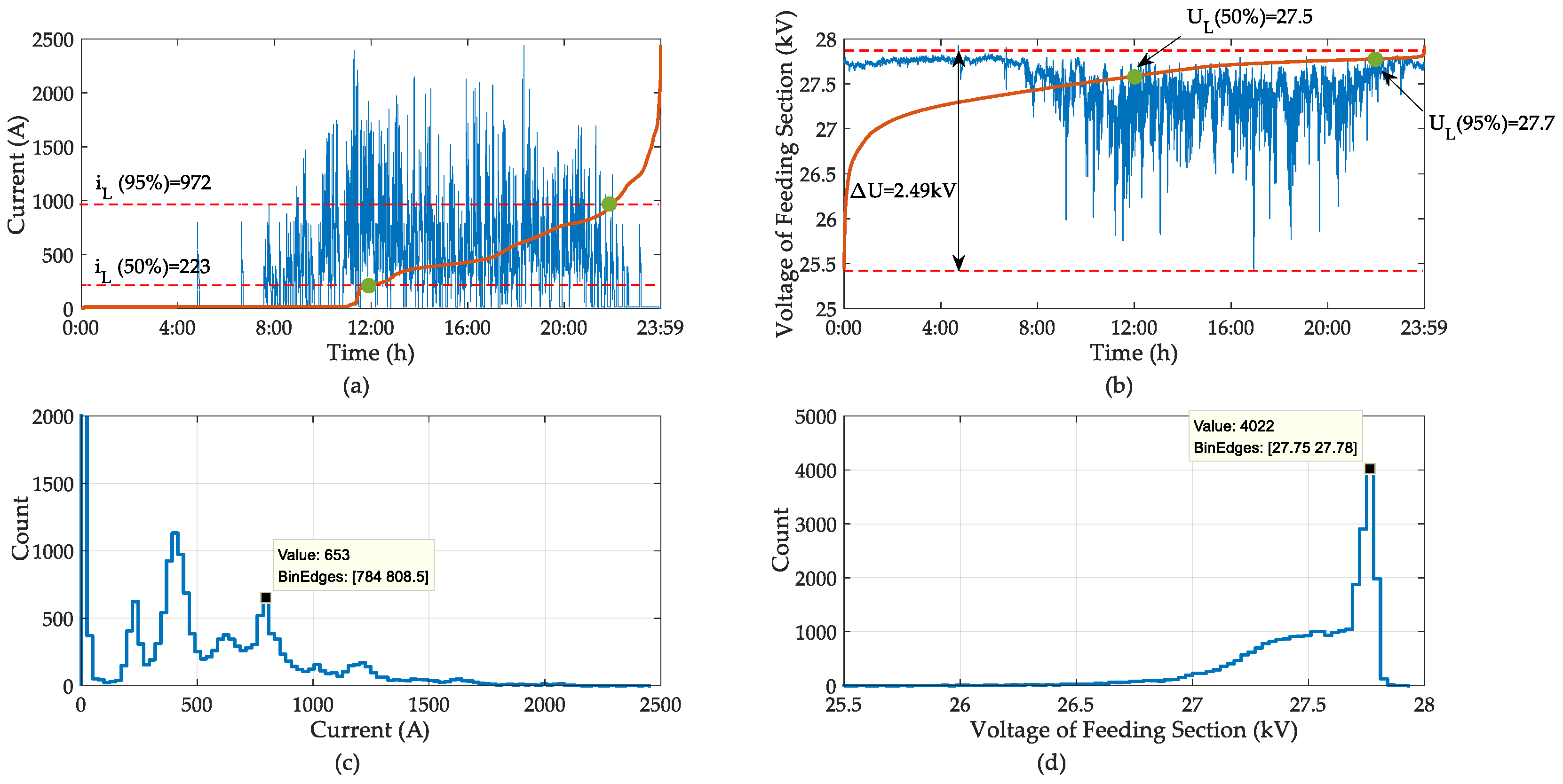
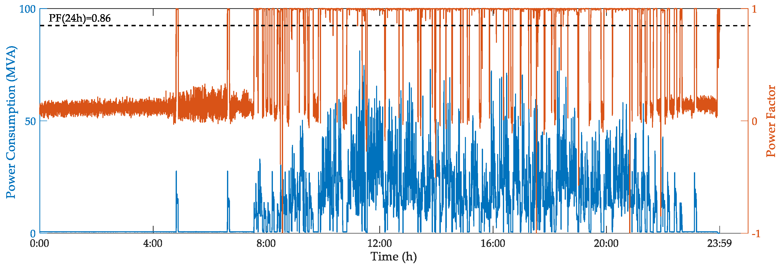
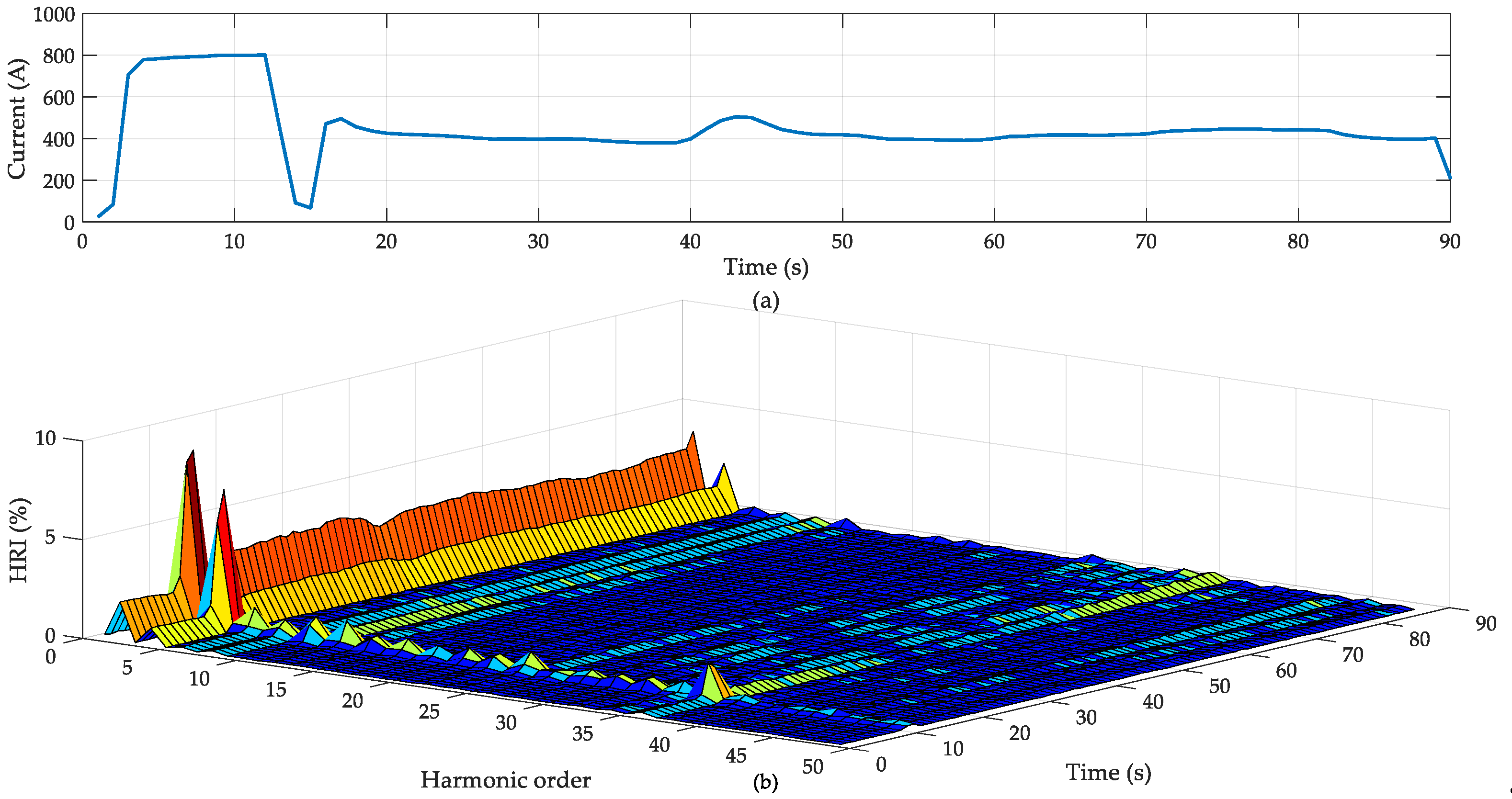
6.1. Field Testing and Designing Parameter of TCL-CTF

As an illustration, a field testing of a typical railway has been implemented in China, in which the sampling frequency of power-quality monitor is 10 KHz, and the testing cycle is 24 h. The main circuit of the traction substation (TSS) and the monitoring points are shown in Figure 6a, the CT1 to CT4 are the high-voltage current transformers of the single-phase traction side, which was utilized for accurately measuring the currents for different feeding sections; PT1 and PT2 are the voltage transformers of the single-phase traction side, which are used for accurately measuring the busbar voltage; the CT5 and PT3 are the current and voltage transformer for the three-phase power grid side, respectively. The monitoring points are installed on these transformers’ low-voltage side. The equipment’s connection and layout are shown in Figure 6b. Take CT1 and PT1 as examples; the voltage can be measured by using the probe to connect the voltage port, and the current can be detected by warping the Rogowski coils around the current wire. The current sensor uses a Fluke i5s current clamp and Rogowski coils. The rated parameters of the current sensor and current transformer are shown in Table 2. The power quality monitor satisfies the requirements of IEC61000-4-5 and IEC 61000-4-7, which can be used for measuring the harmonic. Alternatively, the various algorithms are presented to improve the accuracy of harmonic detection, such as the adaptive Kaiser self-convolution window in [31], which is an adaptive variational mode decomposition in [32].
An integral load current process is shown in Figure 7a. Since the train is an impact load, the load current of the feeding section could rapidly increase from 0 to 2500 A in a short time when multiple trains accelerated simultaneously. Moreover, the 95% probability value of the load current is 972 A, although the 50% probability value of the load current is 223 A. In Figure 7b, the voltage of the feeding section is associated with the current process; the 25.44 kV and 27.93 kV are the lowest and highest voltage during a day, respectively, which means that the voltage fluctuation has arrived at 2.49 kV due to the intense load change. Furthermore, the 50% probability value of voltage and the 95% probability value of voltage are 27.5 kV and 27.7 kV, respectively. In Figure 7c, the load current is mainly distributed in [392 A 416.5 A], [220 A 245 A], and [784 A 808.5 A] based on the mathematical statistics. In Figure 7d, the voltage of the feeding section is stale in [27.75 27.78] most of the time, which benefits from the strong ability of the power supply. As shown in Figure 8, the instantaneous PF can reach 1 when the trains are running on the railway line, but the avenge PF of the feeding section is equal to 0.86 for the whole day.
On the other hand, the fundamental current variation and harmonic ratio of current (HRI) variation are shown in Figure 9a,b, respectively. When a train is running on the railway line, it not only emits the low-frequency harmonics, such as the third, fifth, and seventh harmonics, but also issues the high-frequency harmonics, especially for 25th, 35th, and 40th harmonics. In recent years, the threat that the high-frequency harmonic variation problem poses to the security of trains has drawn wide attention [18,19]; it is an important influencing factor on traction network resonance. According to the field testing result and published academic research studies [18], the 20th harmonic is an appropriate turning point (ht) of the TCL-CTF.
Based on Section 5.2 and field testing results, the key parameters of the TCL-CTF are shown in Table 3. Moreover, the positive sequence of active power P L + is calculated by the 95% probability value of load current and the 95% probability value of voltage U L .
It should be emphasized that the impact of the impedance frequency of the TPSS should also be considered; an ideal TCL-CTF can not only filter the high-order harmonic, but also move the resonance points of the TPSS to a specific region, which can reduce the probability of resonance. Therefore, based on the field parameters, the simulation model including the TSS and traction net is established by MATLAB/SIMULINK, and then the frequency-scanning module is used to obtain the impedance-frequency response of the TPSS; the impedance-frequency response seen from the train side is shown in Figure 10.
As shown in Figure 10, before the TCL-CTF connects to the TPSS, the resonance points are 1720 Hz (34th) and 2354 Hz (47th); after it connected, one point moves to a low-frequency area (586 Hz, 11th), while the other point moves to the high-frequency area (2616 Hz, 52th). However, the value of the capacitor will decrease as time goes by, the resonance points will also move to the high-frequency area. For example, the resonance points at the 11th can transfer to the 12th or 13th, which possess poor harmonic content relative to another harmonic region, as shown in Figure 9b. Consequently, the TCL-CTF is completely designed via the theoretical calculation; then, it still needs to test its filtering performance by simulation and experiment.

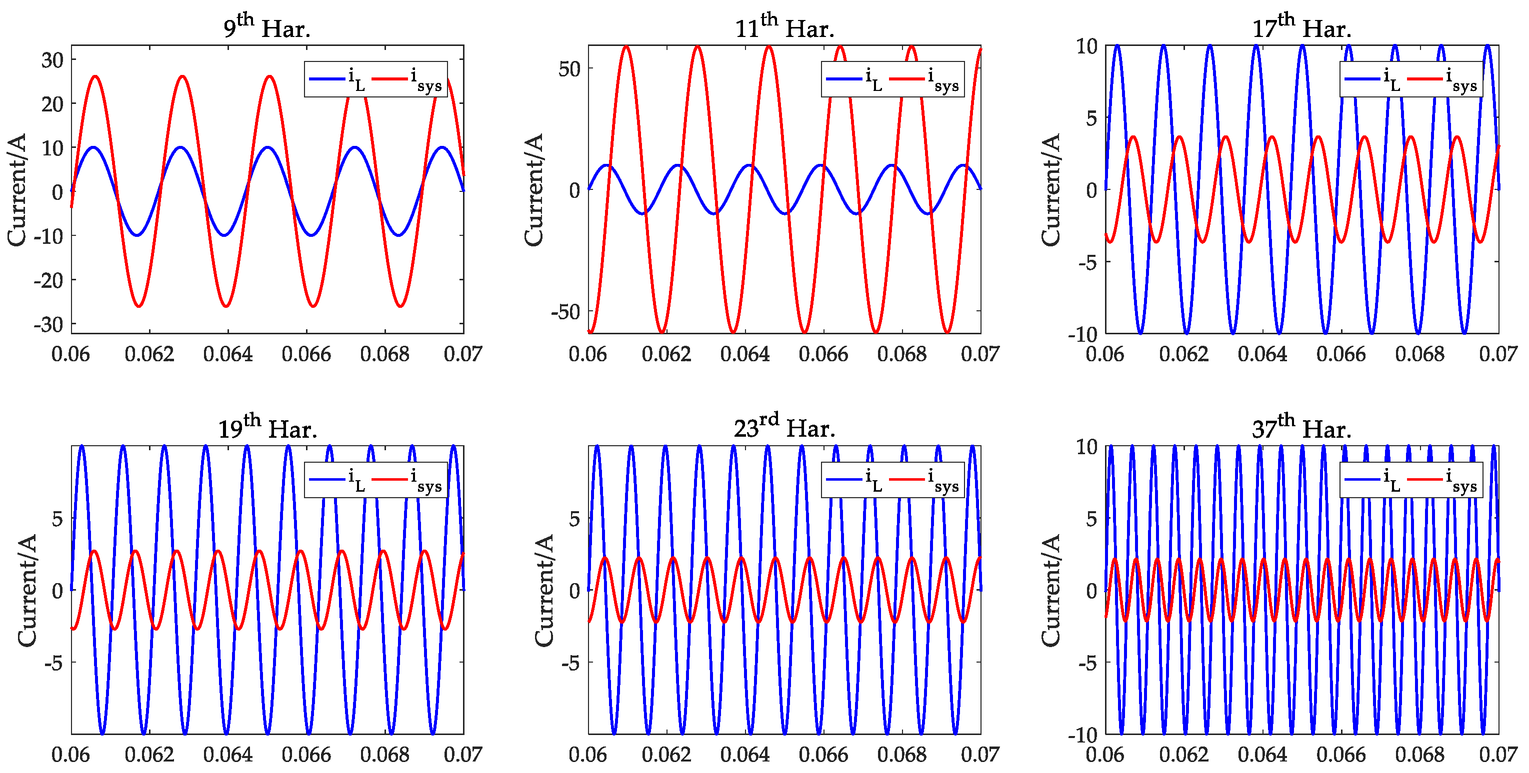
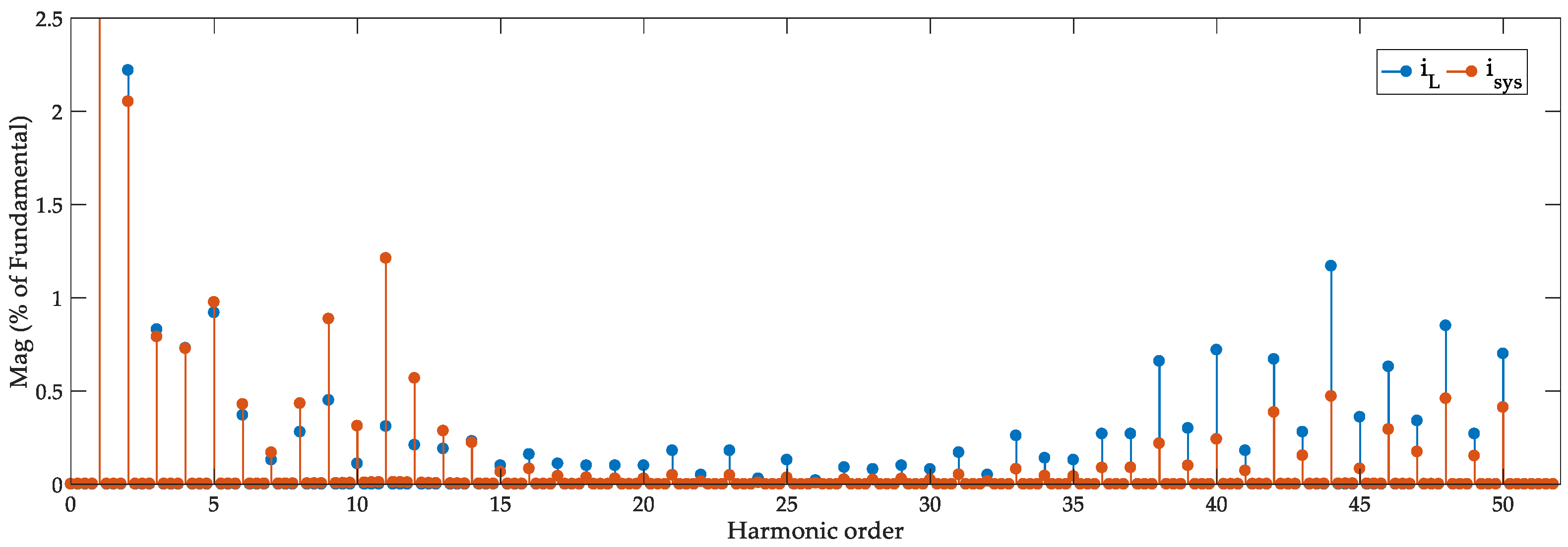
6.2. Vaildation of Filtering Performance

6.2.1. Simulation Results

To simulate the filtering characteristic of the TCL-CTF, a simulation model of the TPSS is established with MATLAB/SIMULINK, as shown in Figure 11. The simulation model assumes the system parameters S s c = 2000   MVA , X/R = 7; the basic parameters of traction net and TT come from the field TSS in Section 6.1; the typical harmonic current model of the train comes from the field testing result.
In Figure 12, the equal amplitude’s currents with the different harmonic order i L are injected to the model respectively, the currents flowing into power system i s y s are measured at the same time. On the one hand, when the ninth and 11th harmonic currents are injected, the i s y s is larger than i L for each frequency, which means that the resonance point of the TPSS is correctly portrayed. On the other hand, it can be seen that the amplitude of i s y s is less than i L when the currents of frequency arrived at the 17th, 19th, 23rd and 37th harmonic currents. Furthermore, the amplitude of i s y s is smaller with the harmonic order increasing. Thus, it can be concluded that the filtering characteristic of the TCL-CTF meets the design requirements, which can filter out the high-frequency harmonic current.
In Figure 13, the real harmonic currents are injected into the model. It can be seen that the high-frequency harmonic components can be effectively diminished by the TCL-CTF. Thus, the designed parameter of the TCL-CTF can effectively filter out the high-frequency harmonics. On the other hand, compared with bode diagram of the TPSS with the TCL-CTF in Figure 10, the resonance point at 586 Hz is accurately portrayed, which verifies that Equation (33) can be used to study the impedance-frequency response.

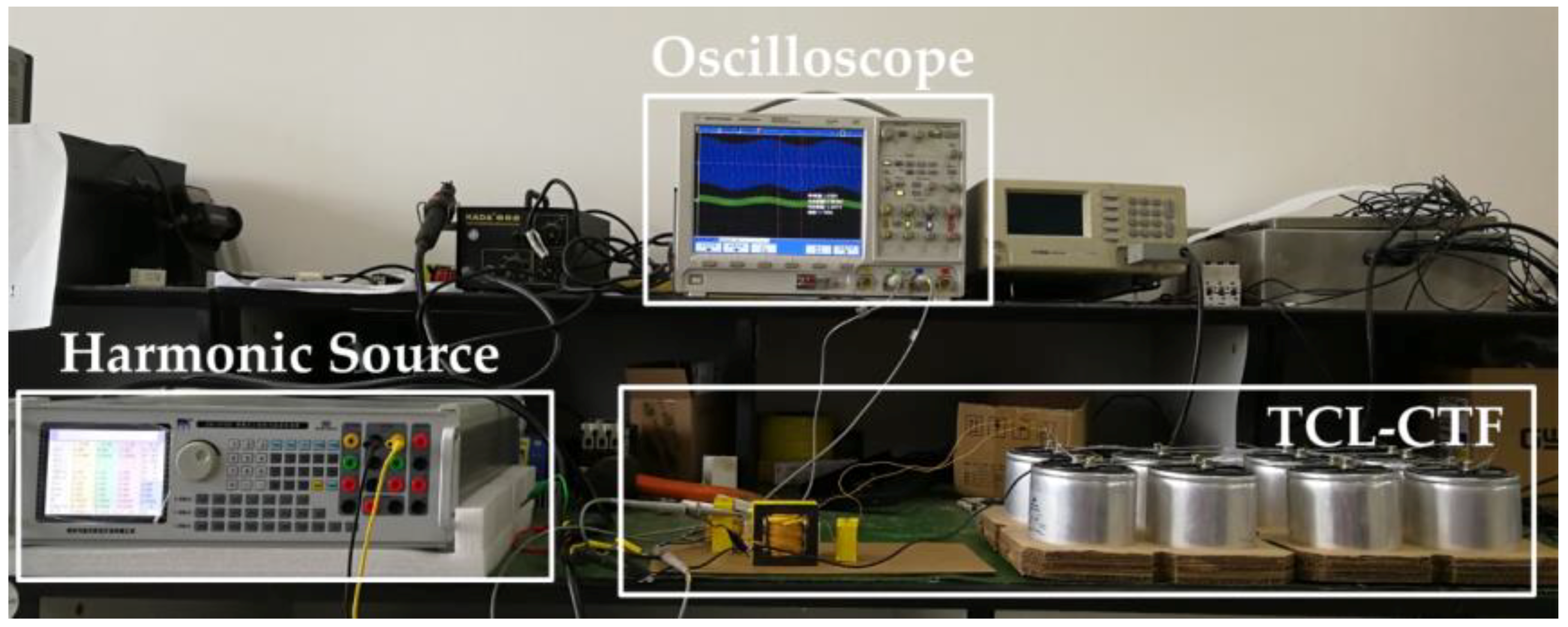
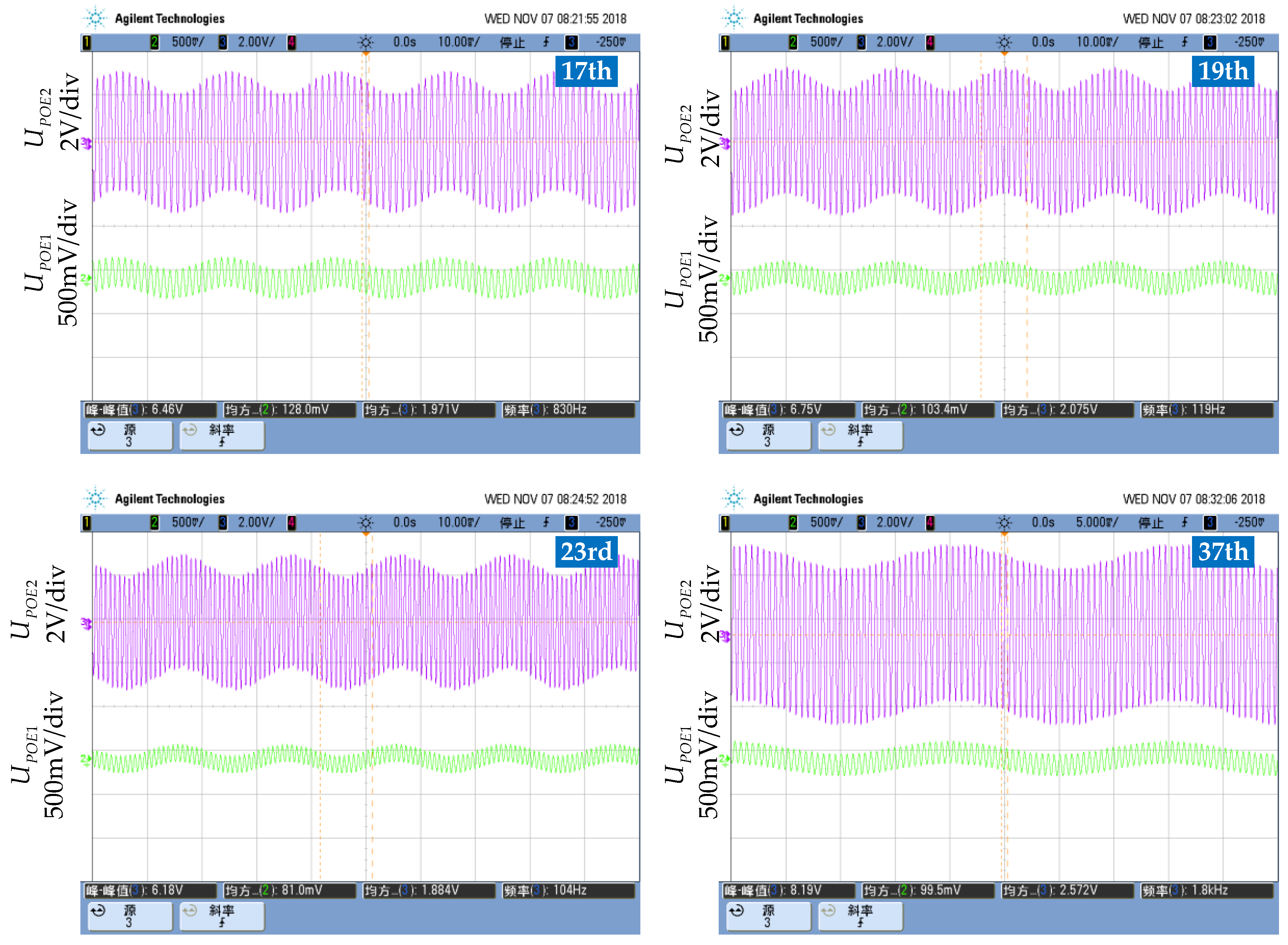
6.2.2. Experimental Results

To test the actual filtering characteristic of the TCL-CTF, an experimental prototype of the TCL-CTF is constructed in the laboratory, as shown in Figure 14. Constrained by the voltage level and actual condition, it is difficult to establish a high-voltage system, TT, and actual traction net in the laboratory. Thus, a passive RL series component can be adopted to portray the impedance-frequency response of these components, and the equivalent impedance can be obtained by scanning the simulation model via using the frequency-scanning module in MATLAB/SIMULINK. The relative values are shown in Table 4. Finally, a passive simplified equivalent circuit is built, as shown in Figure 5. The traction load can be simplified as a harmonic current source. The waveforms are acquired by a DSO-7014A scope recorder.
Figure 15 shows the experimental results of harmonic voltage at the POE1 and POE2, with ninth and 11th harmonics. In Figure 15, the system resonance point around 586 Hz has been verified. The system causes a severe oscillation, causing the scope recorder to not correctly identify the frequency when injecting an 11th harmonic current at POE2. Furthermore, the experimental platform can be used to demonstrate the effectiveness of the TCL-CTF.
Figure 16 shows the experimental results of harmonic voltage at the POE1 and POE2, with the 17th, 19th, 23th, and 37th harmonics. In Figure 16, the harmonic voltage of POE1 is less than 100 mV when the harmonic voltage of POE2 is approximately equal to 2 V, which means that the harmonic current can be effectively filtered out after 19th harmonic. Thus, it can be concluded that the proposed TCL-CTF structure is available to impair the influence of high-frequency harmonics on the TPSS.

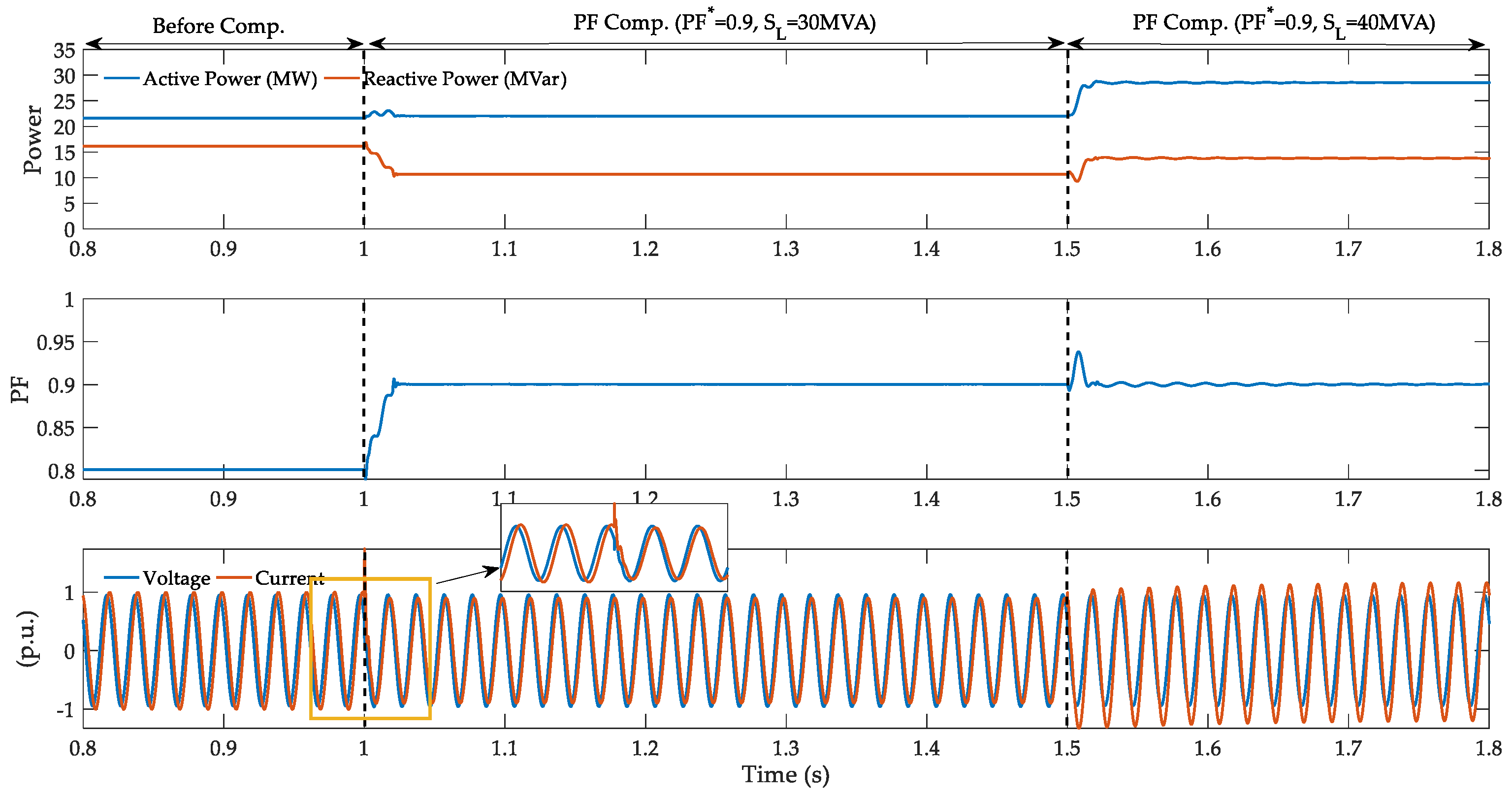
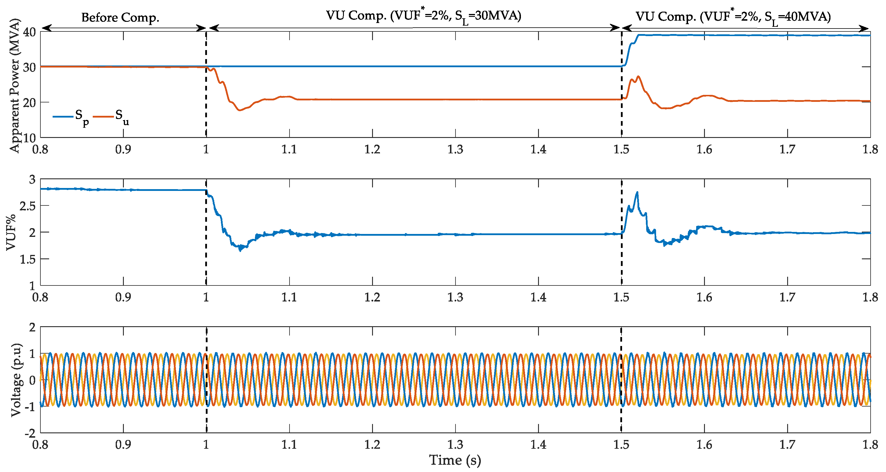
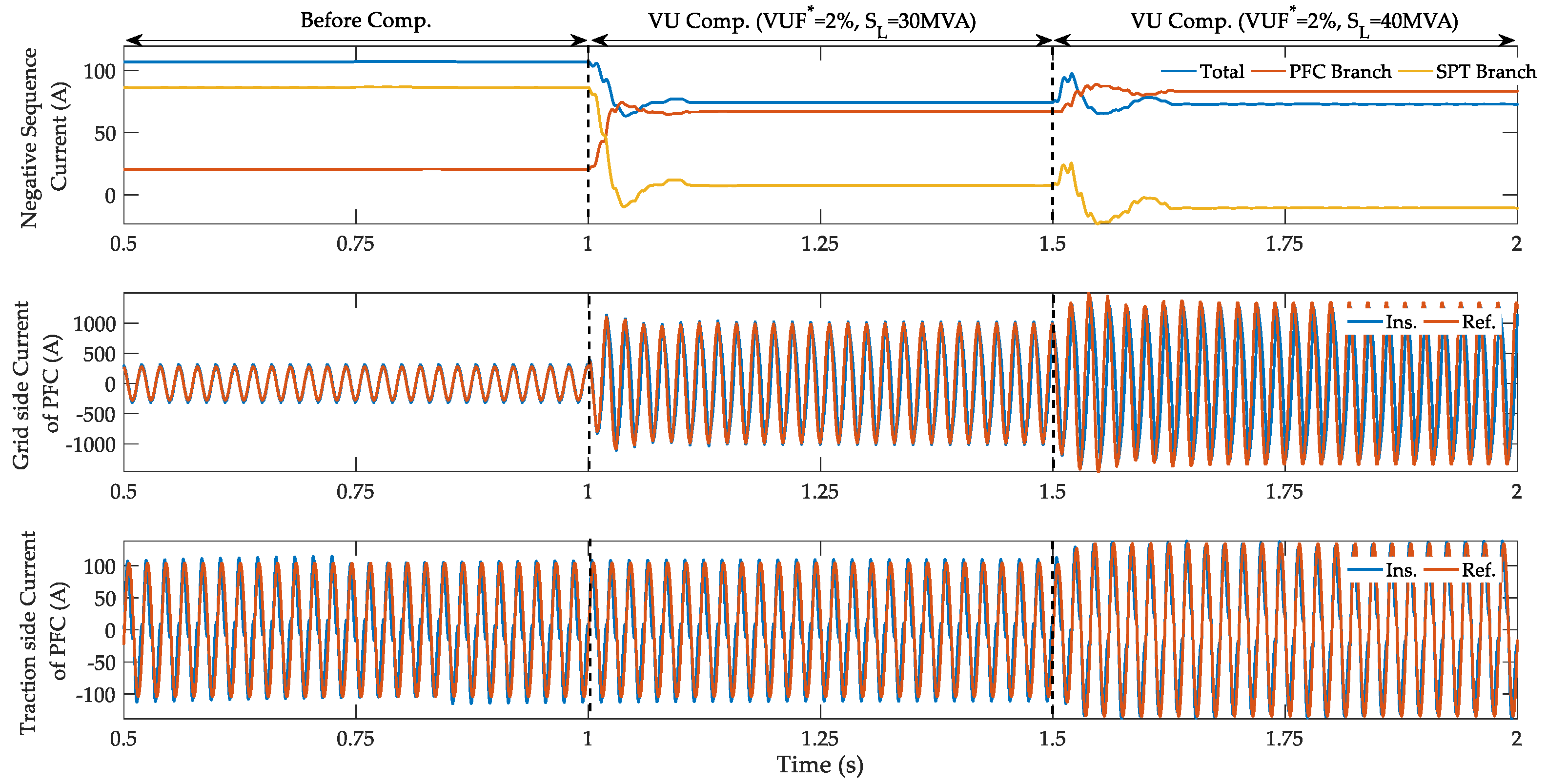
6.3. Vaildation of Compensation Performance

To testify the compensation performance of the hybrid power quality compensation system, a simulation model is established with MATLAB/SIMULINK, as shown in Figure 17. In the simulation model, a cascaded H-bridge multilevel construct is adopted to the PFC; the related parameters are shown in Table 5. Moreover, the constant power source is used for simulating the trains.
Figure 18 shows the simulation results of unbalanced compensation performance. When VU compensation is disabled, the S S p is approximately equal to the S S u 1 , and the VUF of the system arrives at 2.8%. After the VU compensation is enabled at 1 s, the S S u 1 is apparently decreased to 20 MVA, and the VUF of the system is controlled to the VU compensation target 2%. On the other hand, the compensation performance can be still stably maintained, even though the traction load fluctuates from 30 MVA to 40 MVA at 1.5 s. Thus, the proposed control strategy for VU compensation is available, even when the load changes rapidly.
Figure 19 shows the simulation results of the PFC working process with unbalanced compensation. It can be seen that the negative sequence current aroused by traction load is almost injected to the system via the SPT branch when the VU compensation is disabled. After the VU compensation is enabled, the negative sequence current flowing through the SPT branch dramatically decreases with the increase of the PFC branch current, which means that the PFC block is working for VU compensation. Simultaneously, the instantaneous current can respond to the reference current change timely between the grid side and traction side of the PFC.
With regard to reducing the kVA rating of the converter, we compare the strategy proposed in this paper and [17]. The calculation results are shown in Table 6, which are based on Equation (22). After adopting the PFC to transfer the partial active power and optimize and compensate for the VU, 12% of the capacity of PFC can be released, to 29.84 MVA. Furthermore, the proposed control strategy and scheme can save $261,000, at least according to the cost investigate result.
Figure 20 shows the simulation results of reactive power compensation by using the TCL-CTF; the TCL-CTF can compensate for the reactive power of the traction load to 10 MVar via the original 15 MVar, and the PF has been increased to 0.9 from the original 0.8, even when the load changes rapidly. Thus, the proposed control strategy of the TCL-CTF can effectively compensate for the PF.

7. Conclusions

In this paper, a novel hybrid power quality compensation system was proposed to compensate for the VU, reactive power, and filter out the high-frequency harmonics. Furthermore, an optimized compensation strategy was presented to offset the power quality of the TPSS, which meets the requirement of the technology standard. Moreover, the resonance damping and design method of the TCL-CTF were analyzed and discussed. Finally, the effectiveness of the proposed configuration and control approach was demonstrated by the simulation and experiment. Due to adopting the novel hybrid power quality compensation system, the PFC capacity can be apparently reduced by 12% compared with the conventional scheme.

Author Contributions

M.C. and Y.C. proposed the idea, developed the model, performed the simulation works, and wrote the paper. M.W. was in charge of the simulation and experimental works.

Acknowledgments

This work was supported by the Open Project Foundation of National Rail Transportation Electrification and Automation Engineering Technology Research Center (Grant No. NEEC-2018-A03), National Natural Science Foundation of China (Grant No. 51877182) and the Science and Technology Projects of Sichuan Province (Grant No. 2018FZ0107).

Conflicts of Interest

The authors declare no conflict of interest.

Abbreviations

ACAlternating current
APFActive power filter
DCDirect current
EMUElectric multiple unit
IGBTInsulated gate bipolar transistor
LUTLook-up table
MMCModular multilevel converter
MOSFETMetal-oxide-semiconductor field-effect transistor
NSCNegative-sequence current
PFPower factor
PFCPower flow converter
POEPoint of evaluation
PPFPassive power filter
RPCRailway static power conditioner
SPTSingle-phase transformer
SVCStatic var compensator
TCLCThyristor-controlled LC-coupling
TCL-CTFThyristor-controlled L and C-type filter
TPSSTraction power supply system
TTTraction transformer
VUVoltage unbalance
VUFVoltage unbalance factor

References

  1. Chen, Z.; Haynes, K.E. Impact of high-speed rail on regional economic disparity in China. J. Trans. Geog. 2017, 65, 80–91. [Google Scholar] [CrossRef]
  2. Diao, M. Does growth follow the rail? The potential impact of high-speed rail on the economic geography of China. Trans. Res. Part A Policy Pract. 2018, 113, 279–290. [Google Scholar] [CrossRef]
  3. Development Plan of Modern Integrated Transport System in the 13th Five-Year Plan. Available online: http://www.ndrc.gov.cn/gzdt/201703/t20170302_840225 (accessed on 3 February 2017).
  4. Gazafrudi, S.M.M.; Langerudy, A.T.; Fuchs, E.F.; Al-Haddad, K. Power Quality Issues in Railway Electrification: A Comprehensive Perspective. IEEE Trans. Ind. Electron. 2015, 62, 3081–3090. [Google Scholar] [CrossRef]
  5. Chen, Y.; Chen, M.; Tian, Z.; Liu, L.; Hillmansen, S. VU limit pre-assessment for high-speed railway considering a grid connection scheme. IET Gener. Transm. Distrib. 2019, 13, 1121–1131. [Google Scholar] [CrossRef]
  6. Kotsampopoulos, P.; Georgilakis, P.; Lagos, D.T.; Kleftakis, V.; Hatziargyriou, N. FACTS Providing Grid Services: Applications and Testing. Energies 2019, 12, 2554. [Google Scholar] [CrossRef]
  7. Gandoman, F.H.; Ahmadi, A.; Sharaf, A.M.; Siano, P.; Pou, J.; Hredzak, B.; Agelidis, V.G. Review of FACTS technologies and applications for power quality in smart grids with renewable energy systems. Renew. Sustain. Energy Rev. 2018, 82, 502–514. [Google Scholar] [CrossRef]
  8. Serrano-Jiménez, D.; Abrahamsson, L.; Castaño-Solís, S.; Sanz-Feito, J. Electrical railway power supply systems: Current situation and future trends. Int. J. Electr Power Energy Syst. 2017, 92, 181–192. [Google Scholar] [CrossRef]
  9. Morimoto, H.; Ando, M.; Mochinaga, Y.; Kato, T.; Yoshizawa, J.; Gomi, T.; Oozeki, S. Development of railway static power conditioner used at substation for Shinkansen. In Proceedings of the Power Conversion Conference, Osaka, Japan, 2–5 April 2002; pp. 1108–1111. [Google Scholar]
  10. Roudsari, M.H.; Jalilian, A.; Jamali, S. Flexible Fractional Compensating Mode for Railway Static Power Conditioner in a v/v Traction Power Supply System. IEEE Trans. Ind. Electron. 2018, 65, 7963–7974. [Google Scholar] [CrossRef]
  11. Cui, G.; Luo, L.; Li, Y.; Liang, C.; Hu, S.; Xie, B.; Wang, T. YN/VD connected balance transformer-based hybrid power quality compensator for harmonic suppression and reactive power compensation of electrical railway power systems. Int. J. Electr. Power Energy Syst. 2019, 113, 481–491. [Google Scholar] [CrossRef]
  12. Zhang, Z.; Xie, B.; Hu, S.; Li, Y.; Luo, L.; Rehtanz, C.; Krause, O. Reactive Power Compensation and Negative-Sequence Current Suppression System for Electrical Railways with YNvd-Connected Balance Transformer—Part I: Theoretical Analysis. IEEE Trans. Power Electron. 2018, 33, 272–282. [Google Scholar] [CrossRef]
  13. Li, Q. New Generation Traction Power Supply System and its Key Technologies for Electrified Railways. J. Mod. Transp. 2015, 23, 1–11. [Google Scholar] [CrossRef]
  14. Shu, Z.; Xie, S.; Lu, K.; Zhao, Y.; Nan, X.; Qiu, D.; Zhou, F.; Gao, S.; Li, Q. Digital Detection, Control, and Distribution System for Co-Phase Traction Power Supply Application. IEEE Trans. Ind. Electron. 2013, 60, 1831–1839. [Google Scholar] [CrossRef]
  15. He, X.; Ren, H.; Lin, J.; Han, P.; Wang, Y.; Peng, X.; Shu, Z. Power Flow Analysis of the Advanced Co-Phase Traction Power Supply System. Energies 2019, 12, 754. [Google Scholar] [CrossRef]
  16. Dai, N.Y.; Lao, K.; Lam, C. Hybrid Railway Power Conditioner with Partial Compensation for Converter Rating Reduction. IEEE Trans. Ind. Appl. 2015, 51, 4130–4138. [Google Scholar] [CrossRef]
  17. Chen, M.; Li, Q.; Roberts, C.; Hillmansen, S.; Tricoli, P.; Zhao, N.; Krastev, I. Modelling and performance analysis of advanced combined co-phase traction power supply system in electrified railway. IET Gener. Transm. Distrib. 2016, 10, 906–916. [Google Scholar] [CrossRef]
  18. Chen, M.; Roberts, C.; Weston, P.; Hillmansen, S.; Zhao, N.; Han, X. Harmonic modelling and prediction of high-speed electric train based on non-parametric confidence interval estimation method. Int. J. Electr. Power Energy Syst. 2017, 87, 176–186. [Google Scholar] [CrossRef]
  19. Zhang, R.; Lin, F.; Yang, Z.; Cao, H.; Liu, Y. A harmonic resonance suppression strategy for a high-speed railway traction power supply system with a SHE-PWM four-quadrant converter based on active-set secondary optimization. Energies 2017, 10, 1567. [Google Scholar] [CrossRef]
  20. Kalair, A.; Abas, N.; Kalair, A.R.; Saleem, Z.; Khan, N. Review of harmonic analysis, modeling and mitigation techniques. Renew. Sustain. Energy Rev. 2017, 78, 1152–1187. [Google Scholar] [CrossRef]
  21. Lamlom, A.; Ibrahim, A.; Balci, M.E.; Karadeniz, A.; Aleem, S.H.A. Optimal design and analysis of anti-resonance C-type high-pass filters. In Proceedings of the 2017 IEEE International Conference on Environment and Electrical Engineering and 2017 IEEE Industrial and Commercial Power Systems Europe (EEEIC/I&CPS Europe), Milan, Italy, 6–9 June 2017; pp. 1–6. [Google Scholar]
  22. Iwamuro, N.; Laska, T. IGBT History, State-of-the-Art, and Future Prospects. IEEE Trans. Electron. Devices 2017, 64, 741–752. [Google Scholar] [CrossRef]
  23. Wang, L.; Lam, C.; Wong, M. Design of a Thyristor Controlled LC Compensator for Dynamic Reactive Power Compensation in Smart Grid. IEEE Trans. Smart Grid 2017, 8, 409–417. [Google Scholar] [CrossRef]
  24. Wang, L.; Lam, C.; Wong, M. Selective Compensation of Distortion, Unbalanced and Reactive Power of a Thyristor-Controlled LC -Coupling Hybrid Active Power Filter (TCLC-HAPF). IEEE Trans. Power Electron. 2017, 32, 9065–9077. [Google Scholar] [CrossRef]
  25. Wang, L.; Lam, C.; Wong, M. Hybrid Structure of Static Var Compensator and Hybrid Active Power Filter (SVC//HAPF) for Medium-Voltage Heavy Loads Compensation. IEEE Trans. Ind. Electron. 2018, 65, 4432–4442. [Google Scholar] [CrossRef]
  26. Leon, J.; Vazquez, S.; Franquelo, L. Multilevel Converters: Control and Modulation Techniques for Their Operation and Industrial Applications. Proc. IEEE 2017, 105, 2066–2081. [Google Scholar] [CrossRef]
  27. Chen, M.; Liu, R.; Xie, S.; Zhang, X.; Zhou, Y. Modeling and Simulation of Novel Railway Power Supply System Based on Power Conversion Technology. In Proceedings of the 2018 International Power Electronics Conference (IPEC-Niigata 2018-ECCE Asia), Niigata, Japan, 20–24 May 2018; pp. 2547–2551. [Google Scholar]
  28. Kukačka, L.; Kraus, J.; Kolář, M.; Dupuis, P.; Zissis, G. Review of AC power theories under stationary and non-stationary, clean and distorted conditions. IET Gener. Transm. Distrib. 2016, 10, 221–231. [Google Scholar] [CrossRef]
  29. Emanuel, E.A. Summary of IEEE standard 1459: Definitions for the measurement of electric power quantities under sinusoidal, nonsinusoidal, balanced, or unbalanced conditions. IEEE Trans. Ind. Appl. 2004, 40, 869–876. [Google Scholar] [CrossRef]
  30. Yazdani, D.; Mojiri, M.; Bakhshai, A.; JoÓs, G. A Fast and Accurate Synchronization Technique for Extraction of Symmetrical Components. IEEE Trans. Power Electron. 2009, 24, 674–684. [Google Scholar] [CrossRef]
  31. Yao, W.; Teng, Z.; Tang, Q.; Gao, Y. Measurement of power system harmonic based on adaptive Kaiser self-convolution window. IET Gener. Transm. Distrib. 2016, 10, 390–398. [Google Scholar] [CrossRef]
  32. Cai, G.; Wang, L.; Yang, D.; Sun, Z.; Wang, B. Harmonic detection for power grids using adaptive variational mode decomposition. Energies 2019, 12, 232. [Google Scholar] [CrossRef]
Figure 1. Circuit configuration of the hybrid power quality compensation system.
Energies 12 03303 g001
Figure 2. Relationship between the Q T C L _ C T F + , C1, L1, and α. In (a), the varying between the C1 and α, L1 is fixed; in (b), the varying between the L1, α, and C1 is fixed.
Energies 12 03303 g002
Figure 3. Control block of the optimized compensation strategy.
Energies 12 03303 g003
Figure 4. Resonance Damping Analysis. (a) Impedance-frequency response determined by different L1; (b) Impedance-frequency response determined by different R; (c) Impedance-frequency response determined by different C1.
Energies 12 03303 g004
Figure 5. Impedance model of the system, thyristor-controlled L and C-type filter (TCL-CTF), and traction net.
Energies 12 03303 g005
Figure 6. Power quality test in a traction substation (TSS). (a) Main circuit of TSS and monitoring points ( is the monitoring point); (b) Equipment’s connection and layout in the field.
Energies 12 03303 g006
Figure 7. The measurements and statistical results of the α feeding section. (a) The current variation during a day; (b) the voltage variation during a day; (c) the histogram of current in (a); (d) the histogram of voltage in (b).
Energies 12 03303 g007
Figure 8. Power factor (PF) distribution and power consumption of the α feeding section.
Energies 12 03303 g008
Figure 9. Harmonic ratio of current (HRI) variation. (a) Current process of traction load; (b) HRI process of traction load between the second and 50th harmonic order.
Energies 12 03303 g009
Figure 10. Bode diagram of the traction power supply system (TPSS) with the TCL-CTF.
Energies 12 03303 g010
Figure 11. Diagram of filtering characteristic simulation.
Energies 12 03303 g011
Figure 12. Simulation result of filtering characteristic for the TCL-CTF.
Energies 12 03303 g012
Figure 13. Waveforms and fast Fourier transform (FFT) spectrum of iL and i s y s .
Energies 12 03303 g013
Figure 14. Experimental system of the TCL-CTF.
Energies 12 03303 g014
Figure 15. Experimental results of harmonic voltage at the point of evaluation 1 (POE1) and POE2 (9th, 11th harmonic).
Energies 12 03303 g015
Figure 16. Experimental results of harmonic voltage at the POE1 and POE2 (17th, 19th, 23rd, and 37th harmonic).
Energies 12 03303 g016
Figure 17. Diagram of compensation controlling simulation.
Energies 12 03303 g017
Figure 18. Simulation results of unbalanced compensation performance.
Energies 12 03303 g018
Figure 19. Simulation results of the power flow controller (PFC) working process with unbalanced compensation.
Energies 12 03303 g019
Figure 20. Simulation results of reactive power compensation by using the TCL-CTF.
Energies 12 03303 g020
Table 1. The comparison of voltage unbalance (VU) limits between the various countries.
EN 50160EDF Emeraude Contract A.2Grid CodeGB/T 15543-2008
Country/OrganizationsEUFranceBritainChina
VU limit in low-voltage, medium-voltage power system2%2%2% (<150 kV)2%
VU limit in high-voltage, extra-high-voltage power system/2%1.5%2%
Table 2. The key parameters of the current sensor and current transformer.
ParametersValues ParametersValues
Current TransformerRated current of primary side (A)1500Current SensorNominal current range (A)5 A
Rated current of second side (A)5Basic Accuracy1%
Useable frequency (Hz)40~5 K
Table 3. The key parameters of the TCL-CTF.
Input ParametersValuesOutput ParametersValues
cos φ L * 0.90 C 1 (μF)10
cos φ L 0.86 L 1 (H)1.2
P L + (MW)22 C 2 (mF)3.5
U L (kV)27.7 L 2 (mH)2.9
Q C 1 + (MVar)2.45R (Ω)27.12
ht20
Table 4. The impedance parameter of an equivalent system and simplified traction network.
ParametersValues
R S 0.122 Ω
L S 6.27 mH
R n e t 3.5 Ω
L n e t 39.01 mH
Table 5. The parameters of the power flow controller (PFC).
ParametersValues
L g 20 mH
C d c 4000 μF
U d c 3 kV
L t 3 mH
Number of H-bridges5
Table 6. Comparisons between improved strategy and strategy proposed in [17].
StrategySL (MVA)VUF* (%) u P F C _ g ,   u P F C _ t   ( kV ) i P F C _ g   ( A ) i P F C _ t   ( A ) S P F C   ( MVA ) Δ S P F C   ( p . u . )
Case in [17]30227.5105417933.911
Case in this paper30227.598110429.840.88

