Abstract
The powertrain model of the series-parallel plug-in hybrid electric vehicles (PHEVs) is more complicated, compared with series PHEVs and parallel PHEVs. Using the traditional dynamic programming (DP) algorithm or Pontryagin minimum principle (PMP) algorithm to solve the global-optimization-based energy management strategies of the series-parallel PHEVs is not ideal, as the solution time is too long or even impossible to solve. Chief engineers of hybrid system urgently require a handy tool to quickly solve global-optimization-based energy management strategies. Therefore, this paper proposed to use the Radau pseudospectral knotting method (RPKM) to solve the global-optimization-based energy management strategy of the series-parallel PHEVs to improve computational efficiency. Simulation results showed that compared with the DP algorithm, the global-optimization-based energy management strategy based on the RPKM improves the computational efficiency by 1806 times with a relative error of only 0.12%. On this basis, a bi-level nested component-sizing method combining the genetic algorithm and RPKM was developed. By applying the global-optimization-based energy management strategy based on RPKM to the actual development, the feasibility and superiority of RPKM applied to the global-optimization-based energy management strategy of the series-parallel PHEVs were further verified.
1. Introduction
Hybrid electric vehicles (HEVs) combine the advantages of traditional internal combustion engine vehicles and pure electric vehicles [1]. The advantages of HEVs, such as enabling long driving distances, being environment-friendly, and energy savings, make them one of the most practical ways to solve energy and pollution problems [2]. Plug-in hybrid electric vehicles (PHEVs) are improved versions of traditional HEVs with a long single-charge range. Among them, the series-parallel hybrid power system has the advantages of both series and parallel connections, making it capable of adapting to working conditions and reducing fuel consumption.
PHEVs have an inherent problem involving power distribution and mode switching because they have multiple power sources. Therefore, it is necessary to introduce a specific energy management strategy that can rationally distribute the energy flow of the power system. At present, energy management strategies of PHEVs can be divided into two categories: (1) rule-based strategy and (2) optimization-method-based strategy [3].
Rule-based energy management strategies mainly include deterministic rule-based strategies [4,5] and fuzzy logic strategies [6,7,8]. Optimization-method-based strategies can be divided into real-time optimization strategies and global optimization strategies [9,10]. Real-time optimization strategies mainly include the equivalent consumption minimum strategy (ECMS) [11] and model predictive control (MPC) strategies [12,13].
According to the optimal control theory, the sum of local optima is not necessarily the global optimum. For PHEV energy management strategies, it is usually expected to obtain the global optimal solution for fuel economy and emission under the whole driving cycle. The energy management strategy based on global optimization needs to predict all the information regarding driving conditions, and its calculated amount is large, which is difficult to perform in real time [14]. However, global optimization provides theoretical optimal control and is suitable for providing references and evaluation criteria for other energy management strategies [15,16]. The study of energy management strategies based on global optimization is conducive to understanding the shortcomings of rules and developing better real-time control rules [17,18]. At present, research on energy management strategies with global optimization is primarily focused on dynamic programming (DP) [19,20,21], stochastic dynamic programming (SDP) [22], evolutionary algorithms [23,24], and Pontryagin minimum principle (PMP) [25,26,27,28]. However, the PMP algorithm requires the Hamilton function to be continuously differentiable for state variables, which is not suitable for solving strongly nonlinear problems [29]. As the complexity of the model increases, the DP algorithm will face a serious dimension disaster problem, so that the calculation takes a very long time. Moreover, there is no theoretical guidance for choosing the weight coefficient of performance index in DP algorithm [30]. Many scholars have made relevant researches on how to reduce the computational burden of global-optimal-based energy management strategies to shorten the solution time [31,32,33]. The energy management strategies based on global optimization have become the focus of research institutions [34]
In the development of hybrid powertrains, it is necessary to consider both the global optimization of the energy management strategy and the global optimization of the powertrain parameters to ensure the best overall vehicle performance [35]. The energy management strategies based on global optimization have become the important supporting conditions for assembly matching of major automobile manufacturers [36,37]. Chief engineer of hybrid system need to observe the variation tendency between fuel consumption and the size of system’s component from more than 10,000 different components parameter schemes. In an increasingly competitive market, producers hope to shorten the information feedback cycle to shorten the development cycle. Therefore, the solution time of global-optimal-based energy management strategy should be shortened as much as possible. However, as mentioned above, the common global optimization algorithms, the DP algorithm, and the PMP algorithm were computationally expensive, which means these requirements are difficult to realize. Chief engineers of hybrid system are therefore in urgent need of a tool to quickly solve global-optimization-based energy management strategy.
To solve the problems of existing global optimization algorithms and meet the needs of chief engineers of hybrid system, a pseudospectral knotting-based method that solves the global optimization problem of PHEV energy management strategies to improve computational efficiency is proposed in this paper. A bi-level nested component-sizing method combining the genetic algorithm (GA) and Radau pseudospectral knotting method (RPKM) was used to determine the series-parallel PHEV power system scheme with the best fuel economy. It showed that the hybrid-powertrain optimization matching program combined with the RPKM can better meet the needs of the actual development process.
The remainder of this paper is organized as follows. Section 2 discusses modeling of the power demand and hybrid powertrains of PHEVs. Section 3 describes the optimal energy management problem in PHEV powertrains with the objective of minimizing fuel consumption. Section 4 describes the RPKM-based transcription from the optimal control problem to a non-linear programming (NLP) problem and the comparisons between DP and RPM. Section 5 presents the development of a bi-level nested component sizing strategy framework for optimal power management of series-parallel PHEVs running under the new European drive cycle (NEDC) to further demonstrate the high calculation efficiency of the RPKM algorithm. Conclusions are provided in Section 6.
2. Dynamic Model for the Series-Parallel PHEV
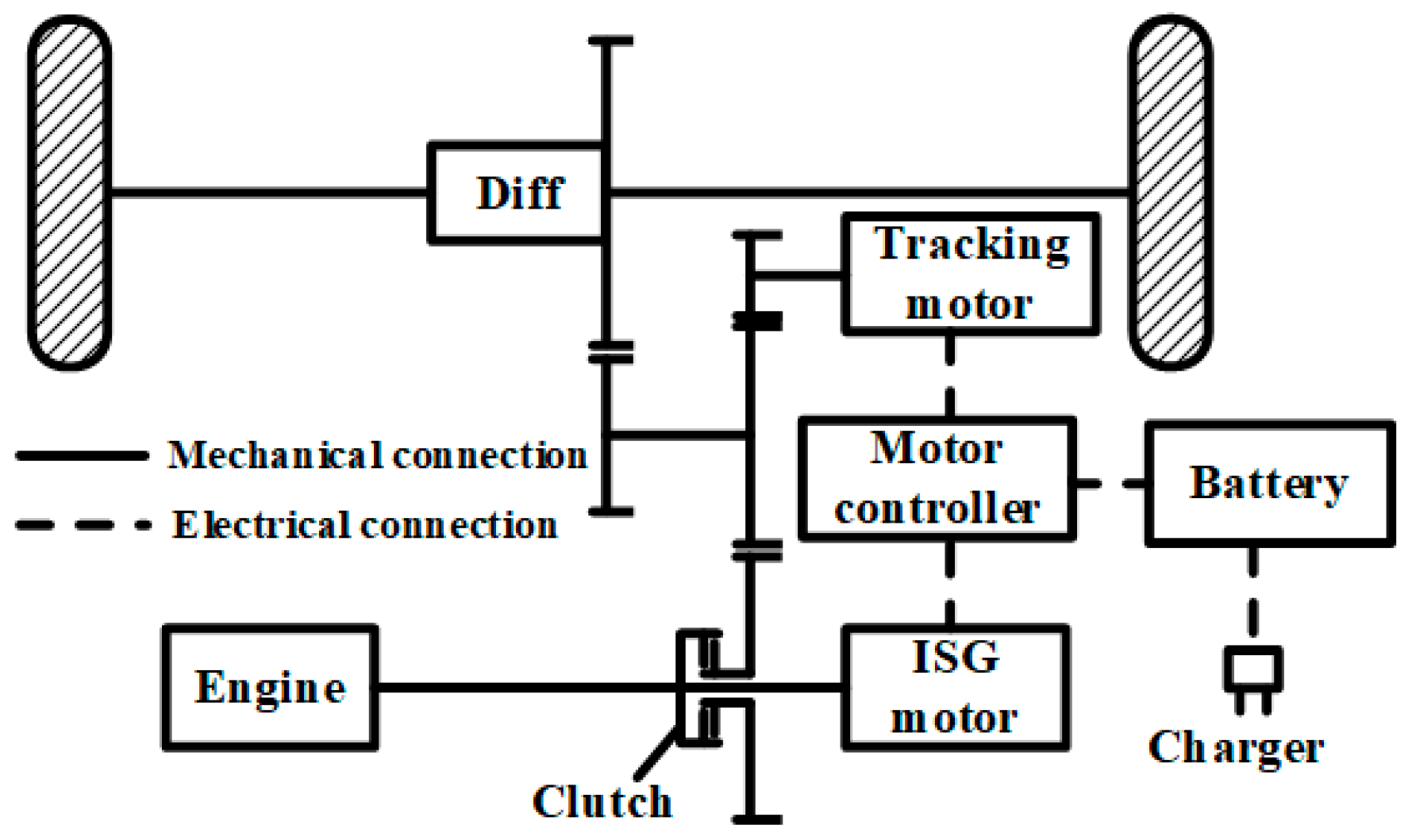
The PHEV considered in this study adopts a series-parallel hybrid power system configuration; its specific structure is shown in Figure 1. The configuration is mainly composed of the engine, integrated starter generator (ISG) motor, tracking motor (TM), and power battery. The power coupling mechanism is a simple gear transmission system.
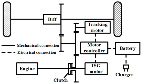
Figure 1.
Configuration of a series-parallel plug-in hybrid electric vehicles (PHEV) power system.
By controlling the operating state of the tracking motor and the ISG motor and the release and combination of the clutch, the hybrid system shown in Figure 1 can achieve different working modes, including pure electric drive mode, series drive mode, pure engine drive mode, parallel drive mode, brake energy recovery mode, and parking charge mode. The series-parallel mode in which the clutch is combined and the ISG motor operates is not considered. Because the general parallel mode can meet all high load requirements, this mode cannot be used in actual operation. Moreover, in this mode, it is difficult for the ISG motor to work at a suitable working point; therefore, charging efficiency cannot be guaranteed.
The values of the key parameters of the hybrid system are given in Table 1.

Table 1.
Key parameters of series-parallel PHEV power system.
2.1. Engine Model
In the global optimization study of PHEV energy management strategies, we only focused on the fuel consumption of the PHEV under specific target conditions, regardless of the complex physical and dynamic response processes inside the engine. Ignoring the dynamic characteristics of the engine and the effect of the heat exchange process on fuel consumption, the instantaneous fuel injection rate of the engine depends only on its output speed and output torque. According to the experimental data of a typical engine, an analytical model of the universal and external characteristics of the engine was established using the least squares method. To avoid the morbid phenomenon in the fitting process, the engine speed and torque were normalized before fitting. The instantaneous fuel injection rate after two-dimensional and five-polynomial fitting and normalization can be expressed as follows:
where is the instantaneous fuel injection rate of the engine, g/s; is the fitting coefficient; is the output torque of the engine, ; is the maximum output torque of the engine, ; is the output speed of the engine, r/min; is the maximum output speed of the engine, r/min.
The R-square of the above polynomial fitting process is 0.9998, which is very close to 1, indicating that the fitting effect is very good. The normalized engine fuel consumption rate (g/kWh) is shown in Figure 2.
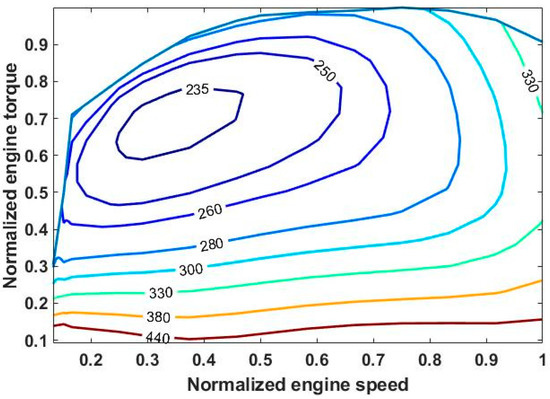
Figure 2.
Normalized fuel consumption rate of engine.
The external torque characteristic of the engine was fitted with a fifth degree polynomial, and the fitted polynomial is as follows:
where is the fitting coefficient. The R-square of this process was 0.9991.
2.2. ISG Motor Model
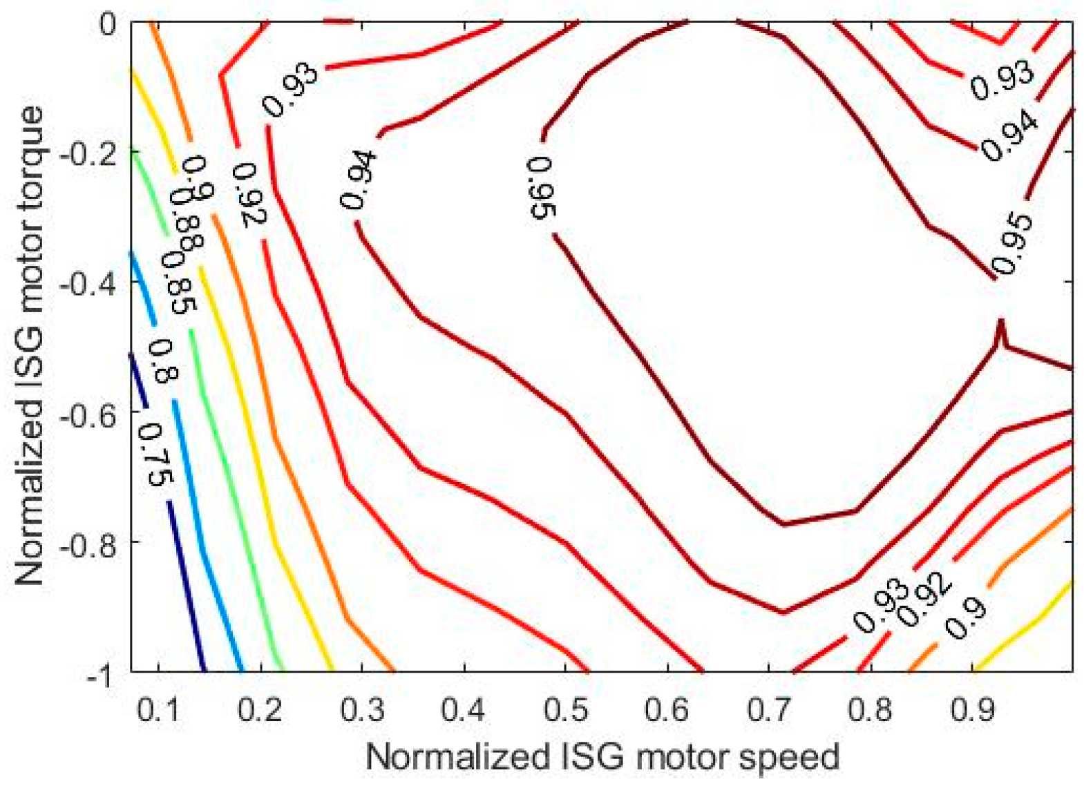
As with engine modeling, the ISG motor was modeled using experimental modeling, focusing only on the input and output characteristics of the motor model, while ignoring the complex internal physical processes. The motor body, inverter, and motor controller were considered as a whole during the modeling process. Ignoring the dynamics and the effect of the heat exchange process on efficiency, the operating efficiency of an ISG motor depends only on its output speed and torque. After two-dimensional and five-polynomial fitting and normalization, the efficiency analysis formula for the ISG motors can be expressed as:
where is the working efficiency of the ISG motor; is the fitting coefficient; is the output torque of the ISG motor, ; is the maximum output torque of the ISG motor, ; is the output speed of the ISG motor, r/min; is the maximum output speed of the ISG motor, r/min.
The R-square of the polynomial fitting process was 0.9932. The efficiency of the ISG motor after fitting and normalization is shown in Figure 3.

Figure 3.
Cloud map of normalized ISG motor efficiency.
2.3. Tracking Motor Model
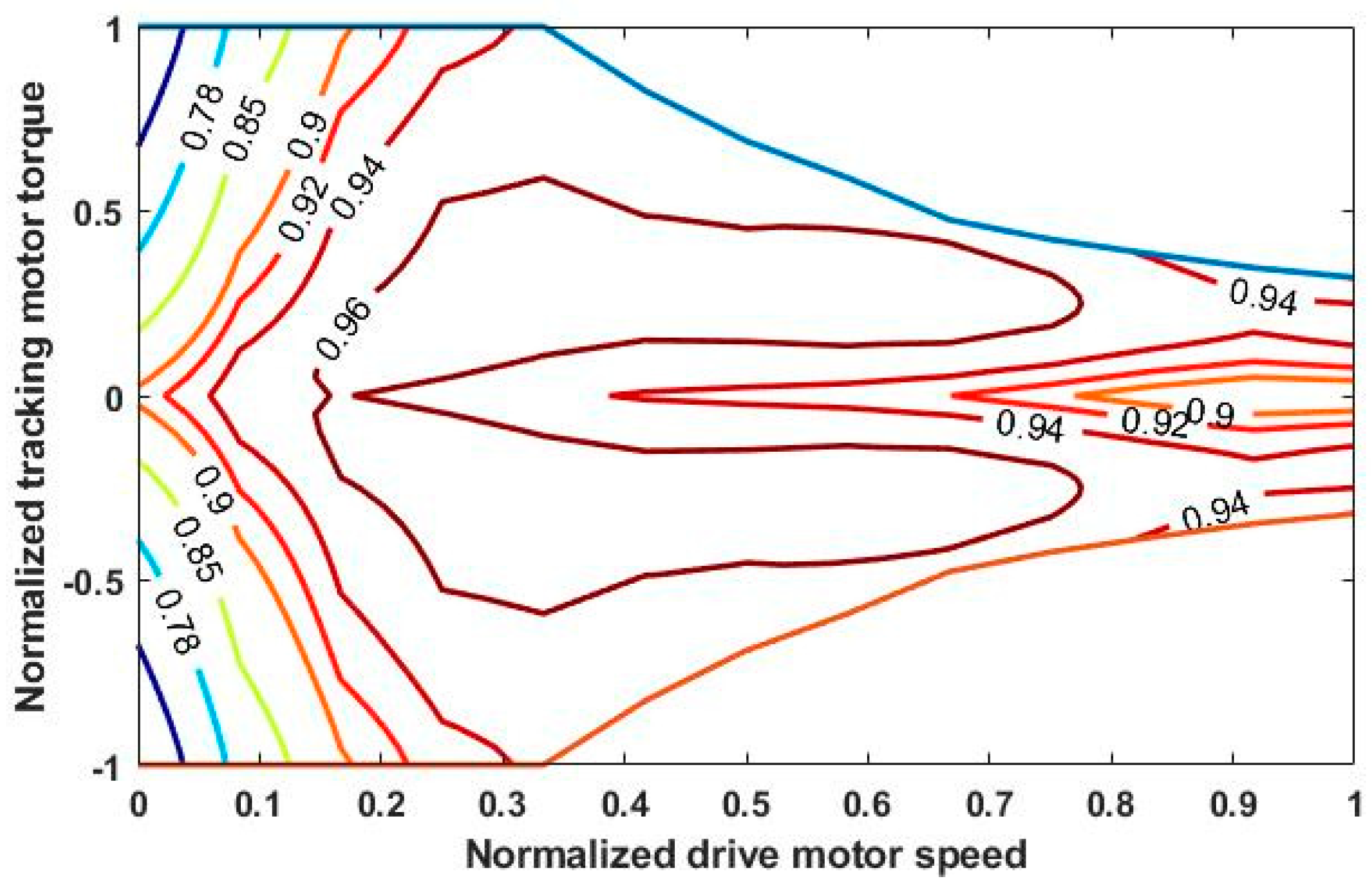
The tracking motor of the series-parallel PHEV can not only be used as an electric motor in the driving state, but also as a generator to recover the kinetic energy of the vehicle in the braking state. The modeling process was consistent with that of the ISG motor. After two-dimensional and five-polynomial fitting and normalization, the efficiency analysis formula for the tracking motor can be expressed as:
where is the working efficiency of the tracking motor; is the fitting coefficient; is the output torque for the tracking motor, ; is the maximum output torque for the tracking motor, ; is the output speed of the tracking motor, r/min; is the maximum output speed of the tracking motor, r/min.
The R-square of the polynomial fitting process was 0.9831. The efficiency of the tracking motor after fitting and normalization is shown in Figure 4.

Figure 4.
Cloud map of normalized tracking motor efficiency.
2.4. Battery Model
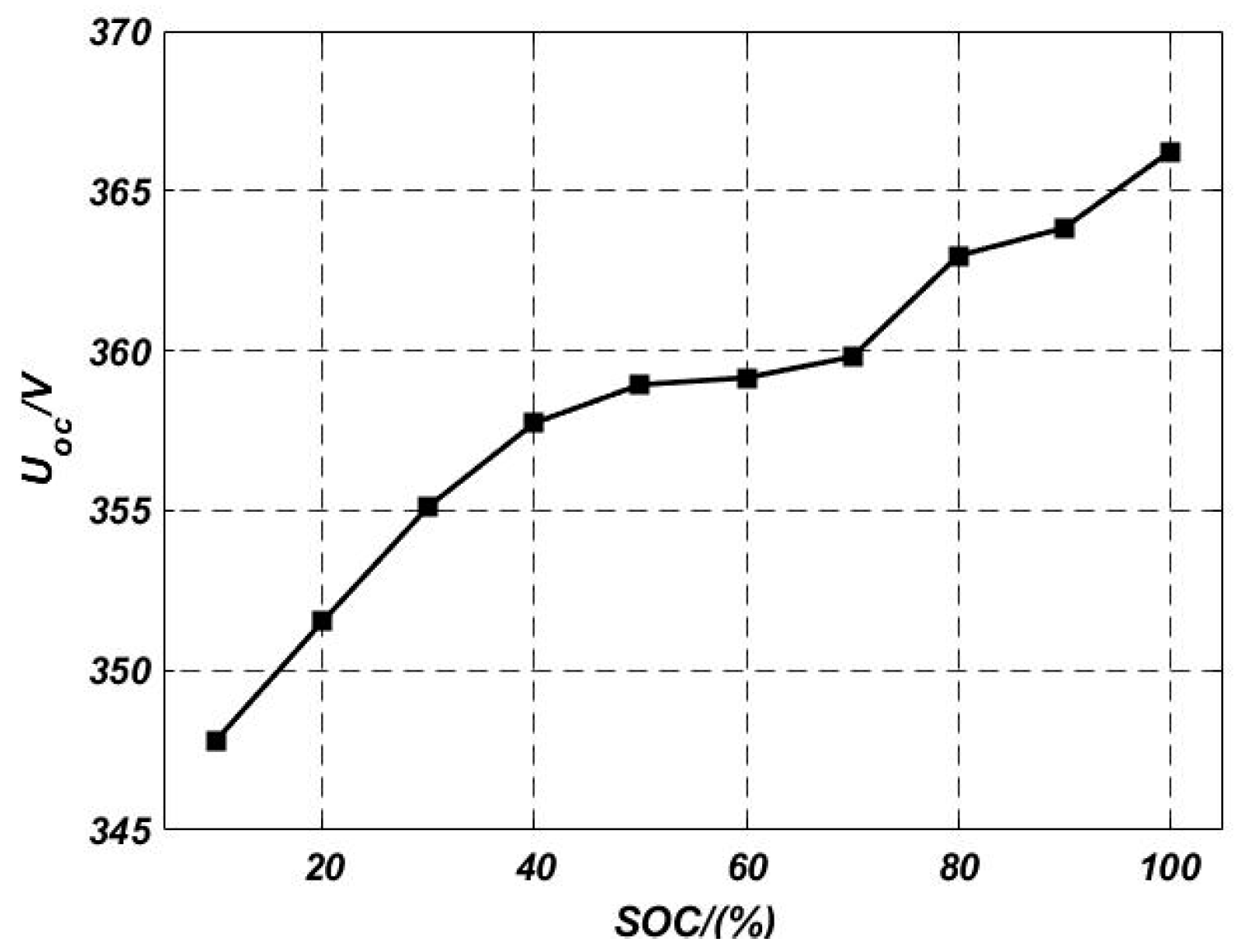
The state of charge (SOC) is an important parameter of the battery pack. In this study, the influence of temperature was ignored; the internal resistance model based on charge-discharge test data was used to model the power battery [38,39]. The equivalent circuit of the power battery is shown in Figure 5.
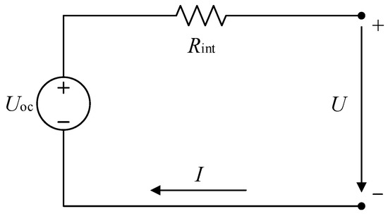
Figure 5.
Equivalent circuit diagram of power battery.
In the figure above, is the open circuit voltage (OCV) of the power battery, V; is the terminal voltage of the power battery; is the internal resistance of the power battery, Ω; is the current of the power battery (discharge is positive, charging is negative), A.
According to the equivalent circuit diagram shown in Figure 5, the relationship between the open circuit voltage and the terminal voltage of the power battery can be expressed by the following equation:
The output power of power battery can be expressed as:
where is the output power of the power battery (discharge is positive, charge is negative), kW.
The SOC of the power battery is calculated by the ampere-hour integration method [40]:
where soc(t0) represents the SOC of the power battery at the initial time; represents the nominal capacity of the power battery, As.
Combined with Equations (5)–(7), the first-order differential of the power battery SOC with time can be expressed as:
Based on the battery module, the relationships between the OCV and internal resistance and SOC are shown in Figure 6 and Figure 7, respectively.

Figure 6.
Battery OCV as a function of battery SOC.
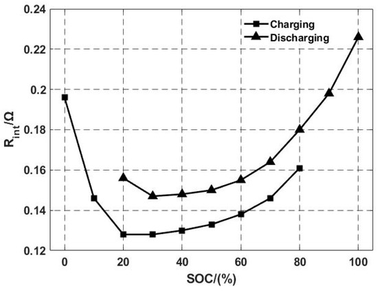
Figure 7.
Resistance as a function of battery SOC.
2.5. Clutch Model
In the series-parallel hybrid system used in this study, the clutch was mainly used to switch between the series and parallel working modes. Therefore, in the backward simulation model, only the separated and combined states are considered; the dynamic characteristics of the clutch are ignored, and the separation and coupling process of the clutch is considered to be completed in an instant.
2.6. Longitudinal Dynamic Model of whole Vehicle
In the problem of optimal control of the energy management of the series-parallel PHEV, the fuel economy index of the whole vehicle is the main concern; therefore, the dynamic model of the whole vehicle only involves the longitudinal dynamic part. The running resistance includes rolling resistance, air resistance, slope resistance, and acceleration resistance, which can be expressed by the following formula:
where F is the sum of all motion resistance forces, ; m is the vehicle mass, kg; g is the gravity constant, ; f is the rolling resistance coefficient; i is the slope of the road; is the aerodynamic drag coefficient; A is the frontal area of the vehicle, ; is the vehicle speed, ; is the rotational inertial coefficient. The torque demand of the driving wheel can be calculated as follows:
where r is the tire effective radius, m. The expression for torque balance of the whole vehicle is:
where is the output torque for mechanical brakes.
2.7. Summary
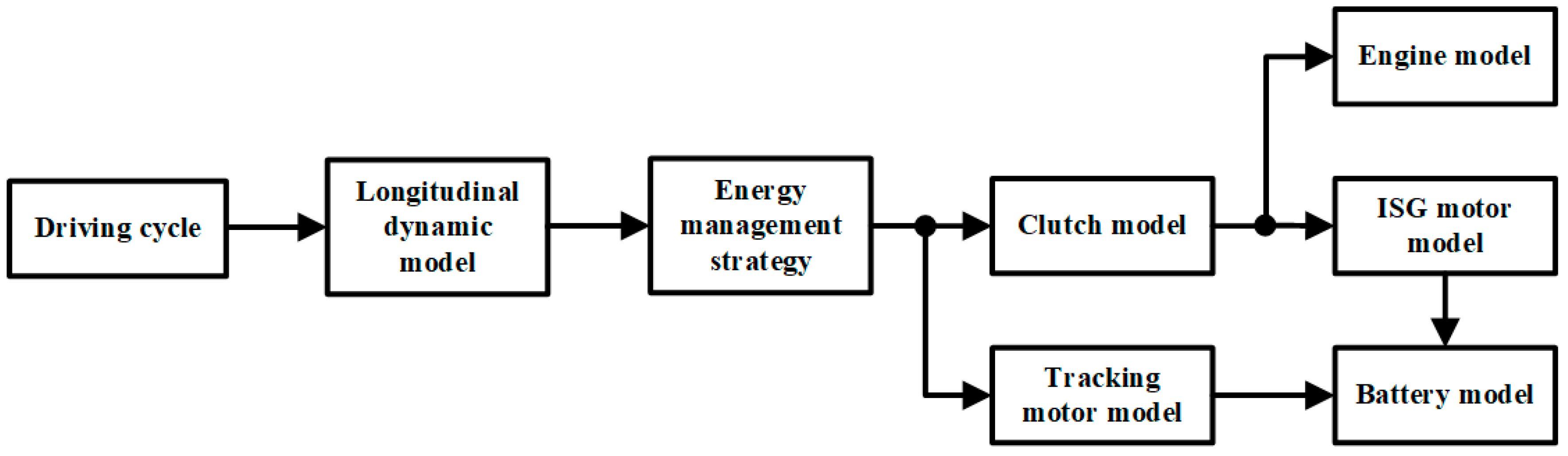
The backward simulation model of the series-parallel PHEV includes the above engine model, ISG motor, tracking motor, power battery, clutch, and vehicle longitudinal dynamics models. The establishment of the backward simulation model was completed by programming in Matlab. The simulation process is shown in Figure 8.
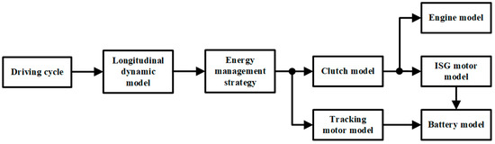
Figure 8.
Backward simulation flowchart for series-parallel PHEV.
3. Optimal Control Problem of Series-Parallel PHEV Energy Management Strategy
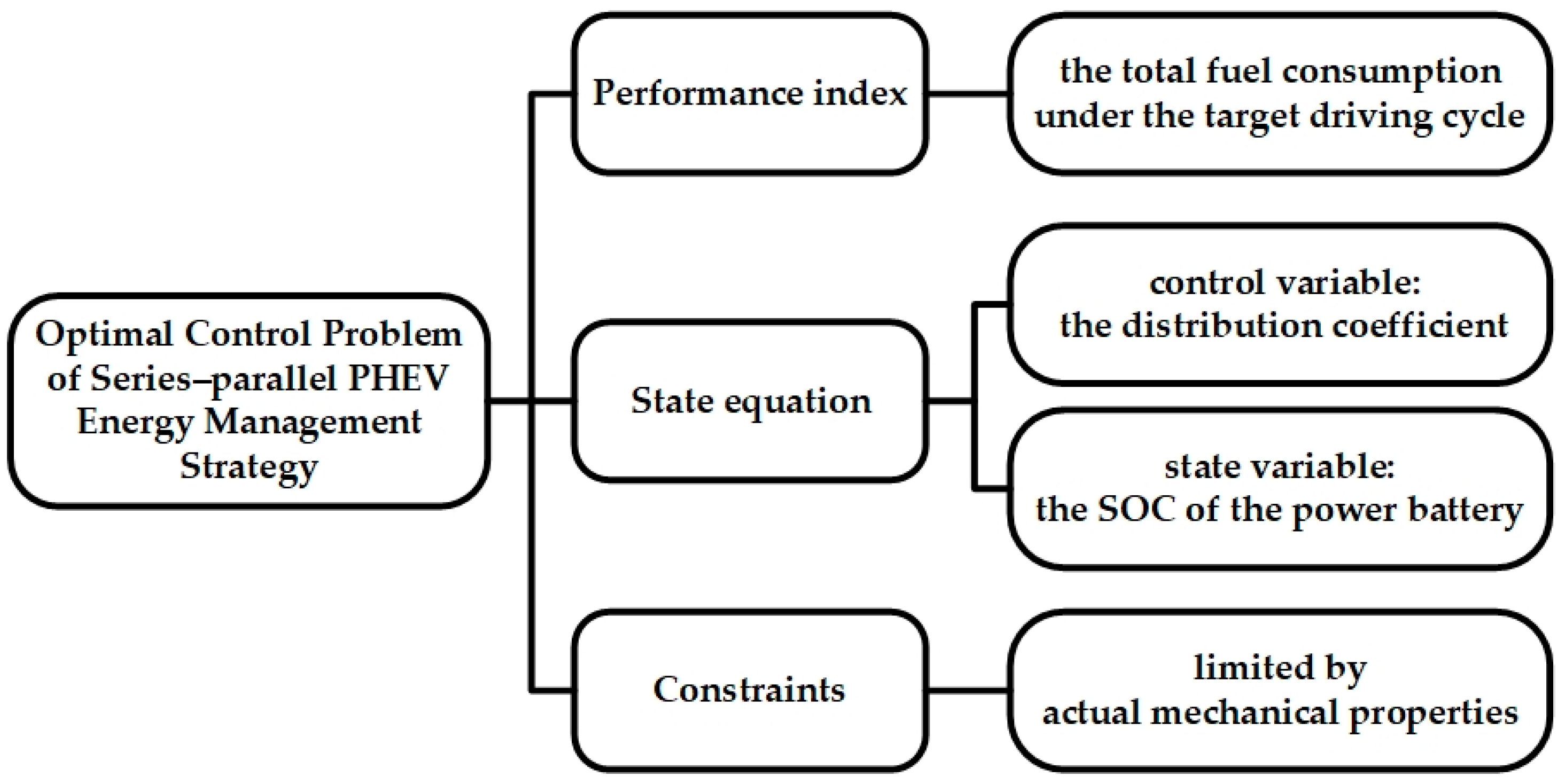
Although the PHEV has an infinite number of combinations of control variables, there is always a method for power distribution for obtaining optimal fuel economy under certain target driving cycles. Therefore, the essence of the optimal control problem of PHEV energy management is finding the best combination of control sequences to minimize the performance index under the target driving cycle. The optimal control problem framework of series-parallel PHEV energy management strategy is shown in Figure 9.
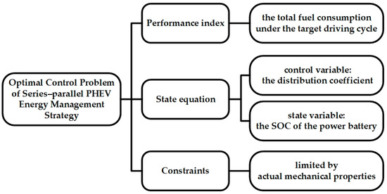
Figure 9.
The optimal control problem framework of series-parallel PHEV energy management strategy.
3.1. Performance Index
When the series-parallel PHEV needs to maintain the charge-discharge balance of the power battery under certain working conditions, its performance index can be expressed as:
where is the total fuel consumption under the target driving cycle, g; represents the fuel consumption of the engine at stage k, g; is the penalty factor; is the expected SOC value at the terminal moment. By adjusting the penalty factor reasonably, the SOC of the power battery can be kept unchanged before and after the driving cycle.
3.2. State Equation
The series-parallel PHEV has multiple working modes, and the energy distribution modes of different working modes are also different. In the pure electric drive mode and pure engine drive mode, there is only one power source that provides energy. In the series drive mode, power is distributed between the auxiliary power unit (APU) and power battery. In the parallel drive mode, torque is distributed between the engine and tracking motor. In the braking energy recovery mode, torque distribution is performed between the tracking motor and mechanical brake. To clearly represent the subtle differences in the equations of state in different working modes, the distribution coefficient was chosen as the only control variable for the system. In addition, according to the structural characteristics of the series-parallel PHEV, the SOC of the power battery was selected as the only state variable of the system.
The state equation for a series-parallel PHEV can be written as:
where and respectively represent the SOC of the power battery at moment and moment ; represents the OCV of the power battery at moment , V; represents the internal resistance of the power battery at moment , Ω; is the output power of the power battery at moment , kW.
It should be pointed out that the difference in the state equations corresponding to different working modes is that the expression for the output power of the power battery is different.
In the pure electric drive mode and series drive mode (the clutch is released), the output power of the power battery can be expressed as:
where represents the efficiency of the tracking motor at moment ; is the distribution coefficient at moment , and its value range is ; represents the output torque of the tracking motor at moment .
When , the required power of the vehicle is completely provided by the power battery, and the PHEV works in the pure electric drive mode. When , PHEV works in the series drive mode, and the output power of the APU can be expressed as:
In the series drive mode, when , the PHEV works in the combined drive mode with the APU and power battery; when , the PHEV works in the APU separate drive mode; when , the PHEV works in the APU drive charging mode, where the output power of the power battery is negative.
In the pure engine drive mode and the parallel drive mode (the clutch is engaged), the output power of the power battery can be expressed as:
The value range of the distribution coefficient is . When , the PHEV works in the pure engine drive mode; when , the PHEV works in parallel drive mode. In these two working modes, the output torque of the engine at moment can be expressed as:
In the braking energy recovery mode (independent of the clutch state), the output power of the power battery is negative and can be expressed as:
The value range of the distribution coefficient is . The reason why the distribution coefficient does not exceed 0.3 is that the highest efficiency of the PHEV in the braking energy recovery process is generally not more than 30%.
Table 2 showed the expression for the output power of the power battery at the different working modes.
Table 2.
The output power of the power battery at the different working modes. APU: auxiliary power unit.
3.3. Constraints
In the solution process, limited by actual mechanical properties, each power component of the PHEV needs to meet the following constraints:
where and represent the minimum and maximum speeds of the engine, respectively, r/min; and represent the minimum and maximum torques of the engine, respectively, N·m; and represent the minimum and maximum speeds of the ISG motor, respectively, r/min; and represent the minimum and maximum torques of the ISG motor, respectively, N·m; and represent the minimum and maximum speeds of the tracking motor, respectively, r/min; and represent the minimum and maximum torques of the tracking motor, respectively, N·m; and represent the minimum and maximum allowable SOC values of the power battery, respectively; and represent the minimum and maximum output power of the APU, respectively, kW; and represent the minimum and maximum output power of the power battery, respectively kW.
4. PHEV Global Optimization Algorithm Based on RPKM
The series-parallel PHEV has multiple working modes, and the state equations of different working modes are also different. Therefore, the energy management optimal control problem is essentially a nonlinear switching-type optimal control problem. For such optimal control problems, to ensure the accuracy and efficiency of the solution, staged processing is required. This section introduces the stage division principle of the Radau pseudospectral knotting method; then, on the basis of the optimal control problem discussed in Section 3, it describes the specific steps for solving the problem by using the Radau pseudospectral knotting method.
4.1. Stage Division Principle
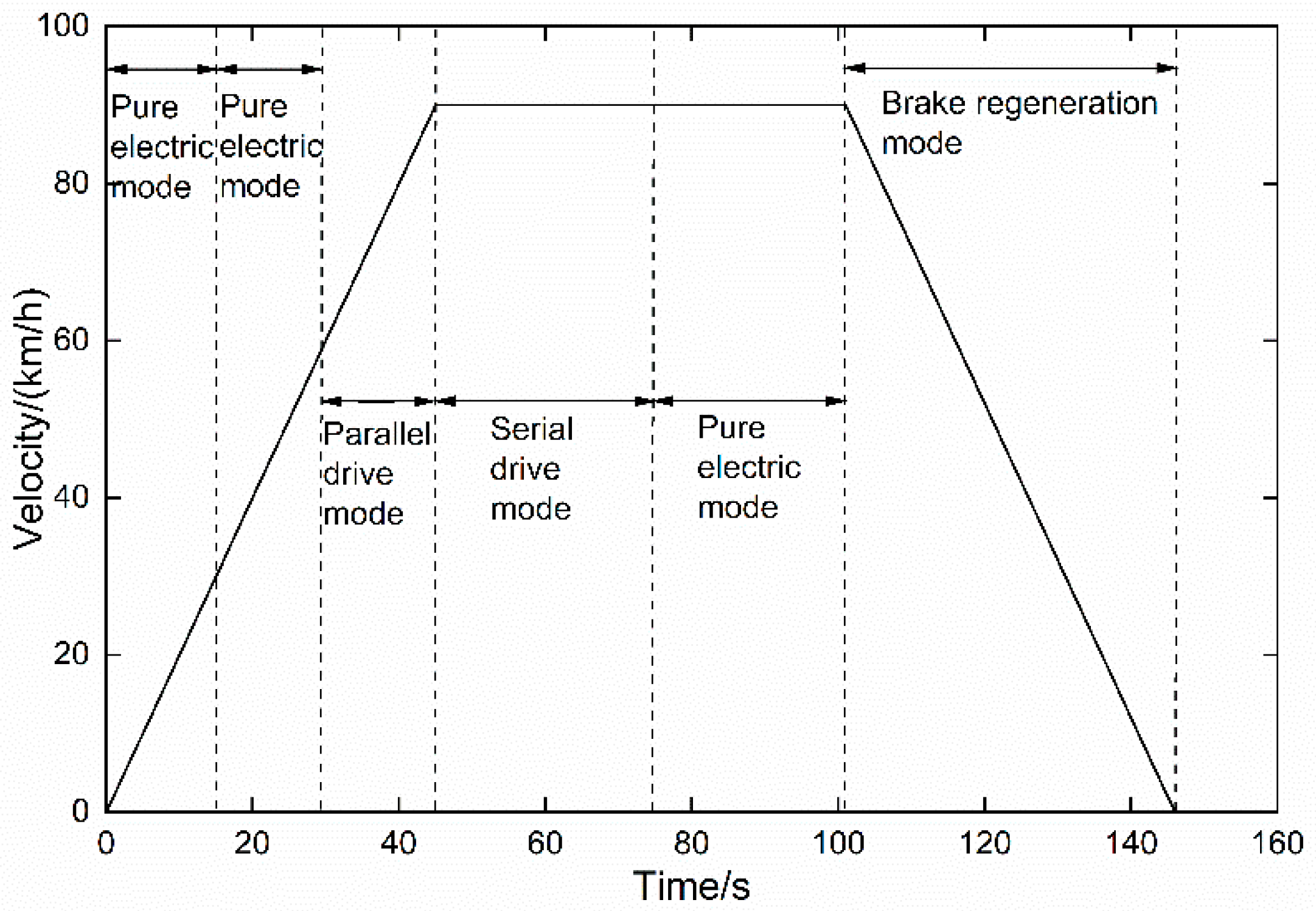
According to the acceleration, the driving conditions of the car can be divided into acceleration, uniform speed, and deceleration (braking) conditions. In theory, the pure electric drive mode, pure engine drive mode, series drive mode, and parallel drive mode of the series-parallel PHEV can work in both accelerated and constant speed conditions. Therefore, its working modes in accelerated and uniform working conditions have infinite combinations. However, in practical engineering applications, to balance the requirements of comfort and life of mode-switching components such as clutches, the working mode of the PHEV does not normally switch frequently (just as conventional internal combustion engines do not frequently shift gears). In addition, the switching time between different working modes in the PHEV energy management optimal control problem is often unknown, and too many switching time points to be optimized will reduce the efficiency of the Radau pseudospectral knotting method. Therefore, before introducing the RPKM, the typical working condition is shown in Figure 10 as an example to determine the stage division principle.
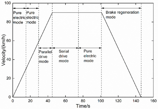
Figure 10.
Stage division.
The mode division rules were set such that only when the speed was above 30 km/h can the engine start to work. In addition, only the pure electric drive mode and parallel drive mode (including pure engine driving mode) were considered under accelerated working conditions; only the pure electric drive mode and series drive mode were considered under uniform speed conditions. Under deceleration (braking) conditions, only the braking energy recovery mode was considered.
4.2. Numerical Solution of RPKM
The solution principle of RPKM is as follows: firstly, converting the time domain of Bolza-type optimal control problem to Legendre orthogonal multi-interval. Secondly, the Lagrange global interpolation polynomials are used to approximate control variables and state variables at Legendre orthogonal multi-intervals. Then, the Gauss-Radau numerical integral and the differential matrix are used to transform the integral type performance function and the differential type state equation, respectively, to approximate the derivative of the state variable to time in the dynamic equation. Based on this, calculus operations can be transformed into algebraic operations of interpolation polynomials. Finally, the original Bolza-type optimal control problem is transformed into the NLP problem with the discrete points of the control variables and state variables as the parameters to be optimized. The NLP problem can be solved using mature large-scale nonlinear optimization software (such as Sparse Nonlinear OPTimizer (SNOPT)). The optimal solution for the global optimization problem can be obtained.
According to the solution principle of RPKM, assuming that the number of stages of the PHEV in a driving cycle is Q. The initial time, the time at the segmentation point and the terminal time were recorded as , and the time point satisfied . The solution process of RPKM includes the following steps.
(1) Time domain conversion
Time intervals for each stage () are converted to the defined interval of the Legendre orthogonal polynomial:
(2) Collocation and discretization
The Legendre–Gauss–Radau (LGR) point used by RPKM can be valued in the half-open interval or . The two collocation methods are equivalent in solving the problem. In this study, we take the LGR collocation of interval , which is the root of polynomial , where is the N-order Legendre orthogonal polynomial:
The time history curves of state variables and control variables in each stage can be approximated using Lagrange interpolation polynomials:
where and are Lagrangian interpolation basis functions, defined as follows:
(3) Dynamic equation constraint transformation into algebraic constraints
After collocation and discretization, the state variable was approximated using the global interpolation polynomial; thus, its derivative could be expressed using the derivative of the interpolation polynomial (22):
where represents the collocation point of stage q, with ; is the differential matrix of order , representing the differential values of the Lagrangian interpolation basis function at each LGR collocation point in stage q, which can be expressed by the following formula:
where .
Combined with Equations (8), (26), and (27), the dynamic equation constraints of the serial-parallel PHEV energy management optimal control problem in stage q can be transformed into algebraic constraints at collocation point :
where represents the output power value of the power battery at collocation point .
The expressions for the output power of the power battery corresponding to each working mode can be obtained from Equations (14)–(18).
(4) Performance index transformation
In the optimal control problem of series-parallel PHEV energy management strategy, the performance index includes two parts, namely engine fuel consumption and power battery power consumption, as shown in Equation (29), which corresponds to the Bolza-type performance index:
where is the oil-to-electricity conversion coefficient, which converts electricity consumed by the power battery into the equivalent engine fuel consumption; and represent the initial and terminal SOC values of the power battery, respectively; is the instantaneous fuel injection rate of the engine, g/s.
For stage q, the form of the performance index depends on the working mode of the PHEV. For the pure electric drive mode and braking energy recovery mode, as the engine does not participate in the work, the performance index at this time only has a nonintegral term (Mayer-type performance index), expressed as follows:
For the pure engine drive mode and parallel drive mode, as the engine always produces power, its performance index contains an integral term (Lagrange performance index), which can be approximated using the Gauss-Radau integral method:
where is the integral weight, defined as:
For the series drive mode, the APU can always operate at the optimum efficiency point owing to decoupling of the APU from the driving conditions. Considering the working efficiency of the engine and ISG motor, the optimal fuel consumption rate of the APU can be expressed as a function of the output power [41]:
where is the optimal fuel consumption rate of the APU under different powers, g/s; is the fitting coefficient; is the output power of the APU, kW. The performance index in the series drive mode can be expressed as:
(5) NLP problem
To facilitate the unification of state equations and performance index of different working modes, , , , , and were used to represent the pure electric drive mode, pure engine drive mode, series drive mode, parallel drive mode, and braking energy recovery mode, respectively. After performing the above steps, the optimal control problem of serial-parallel PHEV energy management was transformed into the NLP problem as shown below.
In Equation (35), ; ; F is the instantaneous fuel injection rate, g/s. To simplify the expression in Equation (35), was used to represent the path constraint of the NLP problem. The detailed expression is given in Equation (19). The optimized variables of the NLP problem are the SOC value at the LGR points, allocation coefficient, and switching time points between different modes, which can be solved using the mature high-dimensional sparse NLP solver SNOPT. Its core algorithm is the sequence quadratic programming method with local superlinear convergence based on line search.
4.3. Result Analysis
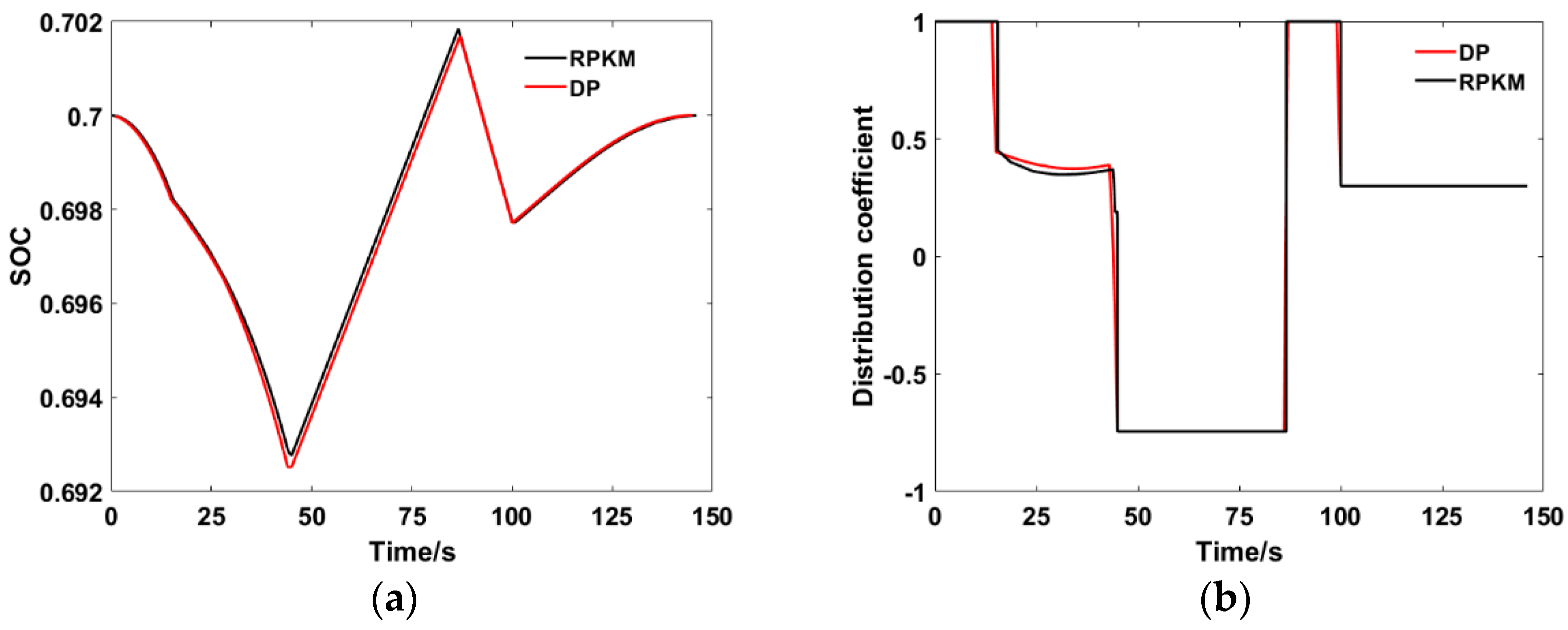
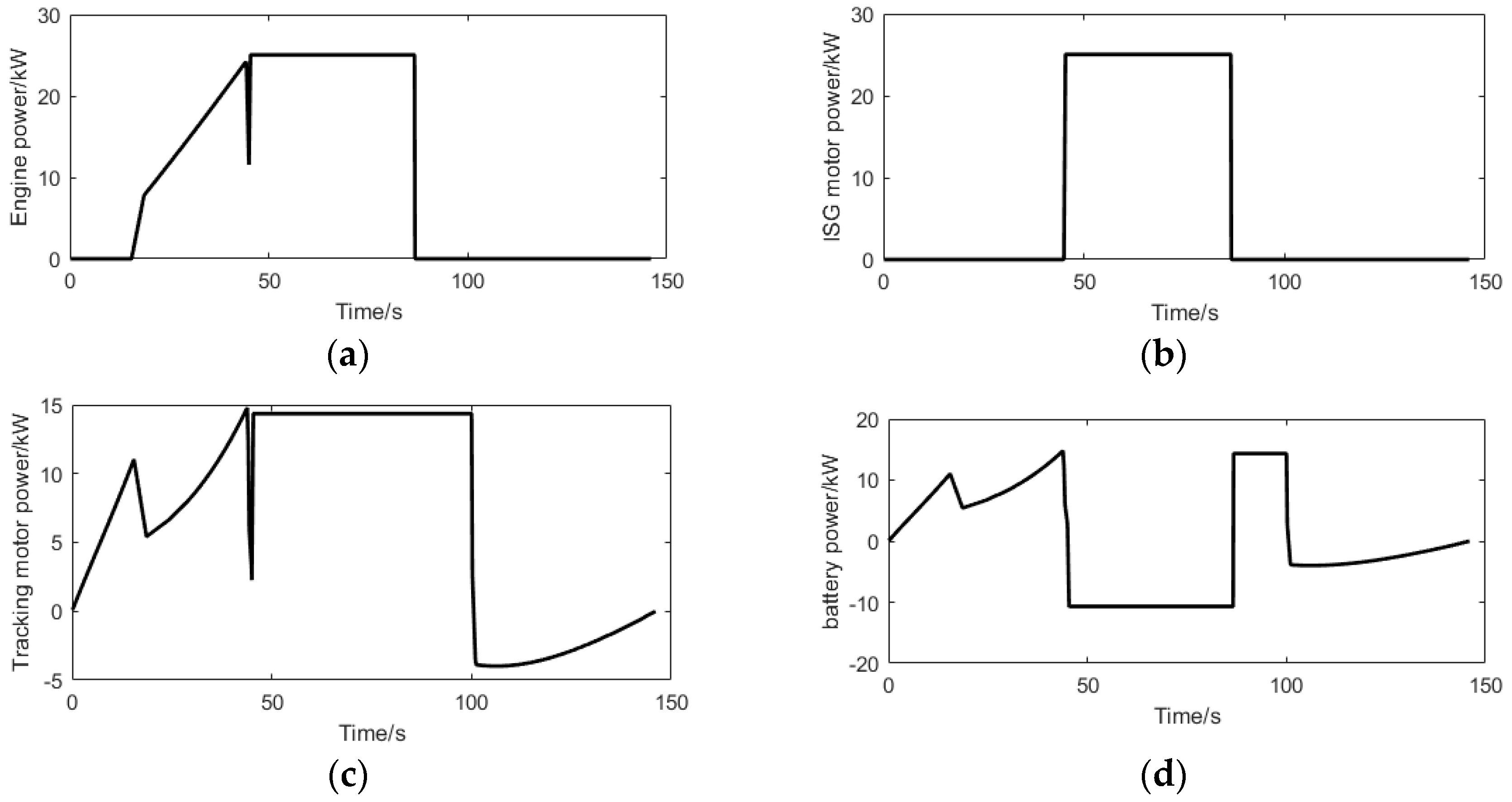
To verify the feasibility of applying the Radau pseudospectral method to the global optimization of the series-parallel PHEV energy management strategy, we used the DP algorithm and RPKM to solve the optimal control problem of energy management under the typical working conditions shown in Figure 11. The working conditions comprise acceleration, uniform speed, and deceleration. The total time was 146 s and the maximum speed was 90 km/h. Figure 12 showed the power of each component of the dynamic system of serial-parallel PHEV under this working condition.
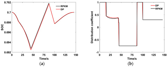
Figure 11.
Comparison of optimization results between DP and RPKM: (a) SOC, (b) Distribution coefficient.
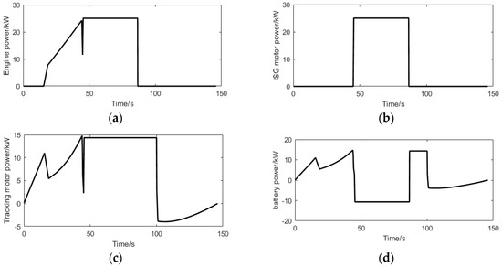
Figure 12.
Power of dynamic system components: (a) Engine, (b) ISG motor, (c) Tracking motor, (d) Battery.
It can be seen from Table 3 that the fuel consumptions of the two global optimization algorithms are close, with a relative error of only 1.81%. It is evident that the two algorithms have very close global optimization capabilities; therefore, the applicability of the RPKM was verified to optimize the energy management strategy of the series-parallel PHEV.
Table 3.
Comparison of optimization results between DP and RPKM.
It is also clear from Table 3 that when solving the same optimal control problem, the DP algorithm takes 32,477 s (9.06 h), while the RPKM only needs 17.98 s. The calculation efficiency of the RPKM is approximately 1806 times higher than that of the DP algorithm, which shows that the RPKM is considerably fast in solving the optimal control problem in series-parallel PHEV energy management.
RPKM treats the problem as a continuous process in each sub-stage and searches for the optimal solution through optimal gradient descent. Compared with DP algorithm, which discretizes all the state variables and control variables of the global optimization problem, and then searches for the optimal solution through a method similar to exhaustive method, RPKM avoids the “dimension disaster” problem; thus, its solving efficiency is higher.
4.4. Error Analysis
The solution errors of RPKM mainly include the approximate errors of state variables and control variables, the differential errors caused by the derivation of Lagrange global interpolation polynomials, and the integral errors in performance indexes. Since the truncation error of Lagrangian global interpolation polynomial is n + 1 times and the algebraic accuracy of Gauss numerical integral is 2n + 1 times, the pseudo-spectral method has a high computational accuracy.
The solution accuracy of DP is greatly affected by factors such as time step (number of stages), the discrete step size of state variables and control variables, and the penalty factors. When the DP algorithm was used to solve the instantaneous fuel consumption corresponding to different state variables at each stage, the instantaneous oil injection rate under the current state is multiplied by the time step to approximate the integral of instantaneous oil injection rate with time, so the integral error of this process was greatly affected by the time step. Theoretically, when the discrete step size of the state variables and the control variables are fixed, the smaller the time step of DP algorithm is, the better the solution accuracy is. However, as the time step decreases, the solving time of DP algorithm will increase exponentially.
Therefore, the following methods are proposed to reduce the integral error in the DP algorithm: the optimal control variable sequence obtained by the DP algorithm is re-substituted into the original optimal control problem. Then the new fuel consumption value was obtained by the forward solution in a time step of 10−6 s. This post-processing method can not only avoid too long solving time, but also ensures the solution accuracy of DP algorithm.
As shown in Table 2, after the same treatment of RPKM, the relative error decreases from 1.81% to 0.12%, indicating that the two algorithms have very close global optimization ability.
5. Bi-Level Nested Component-sizing Method Based on GA and RPKM
In the process of parameter sizing of the PHEV dynamic system, the influence of power system parameters and energy management strategies on vehicle performance is coupled. The parameter optimization of the dynamic system and global optimization of the energy management strategy cannot be considered separately. Therefore, a bi-level nested parameter optimization method based on the GA and RPKM was developed to optimize the final dynamic system of the PHEV.
5.1. Description of the Component-Sizing Problem
The component-sizing problem of the series-parallel PHEV power system is to find the best power system scheme with the best fuel economy while satisfying the power performance index of the vehicle. This component-sizing problem can be expressed using the following mathematical model:
where is the optimization objective; is an n-dimensional vector, representing a set of feasible solutions to the above optimization problem; is the constraint representing the dynamic performance of the vehicle; is the number of constraints; is the number of parameters to be optimized; and , respectively, represent the lower and upper limits of the i-th parameter to be optimized, .
The goal of power system parameter optimization is to achieve the best energy consumption economy. Energy consumption in the optimization process includes the power consumption of the battery and fuel consumption of the engine. The power consumption of the battery and fuel consumption of the engine were converted into corresponding operating costs (where we assumed 1 kWh as equivalent to 300 g of gasoline). The operating cost of the driving cycle was taken as the optimization objective of component sizing of the power system.
The dynamic performance and fuel economy of series-parallel PHEVs are influenced by the engine, ISG motor, tracking motor, power battery, and transmission system. To obtain the best vehicle performance, all relevant parameters need to be optimized. Therefore, the maximum output power of the engine, peak power of the ISG motor, peak power of the tracking motor, total capacity of the power battery, speed ratio of the tracking motor to the wheel, and speed ratio of the engine to the wheel were selected as the optimization variables in this study.
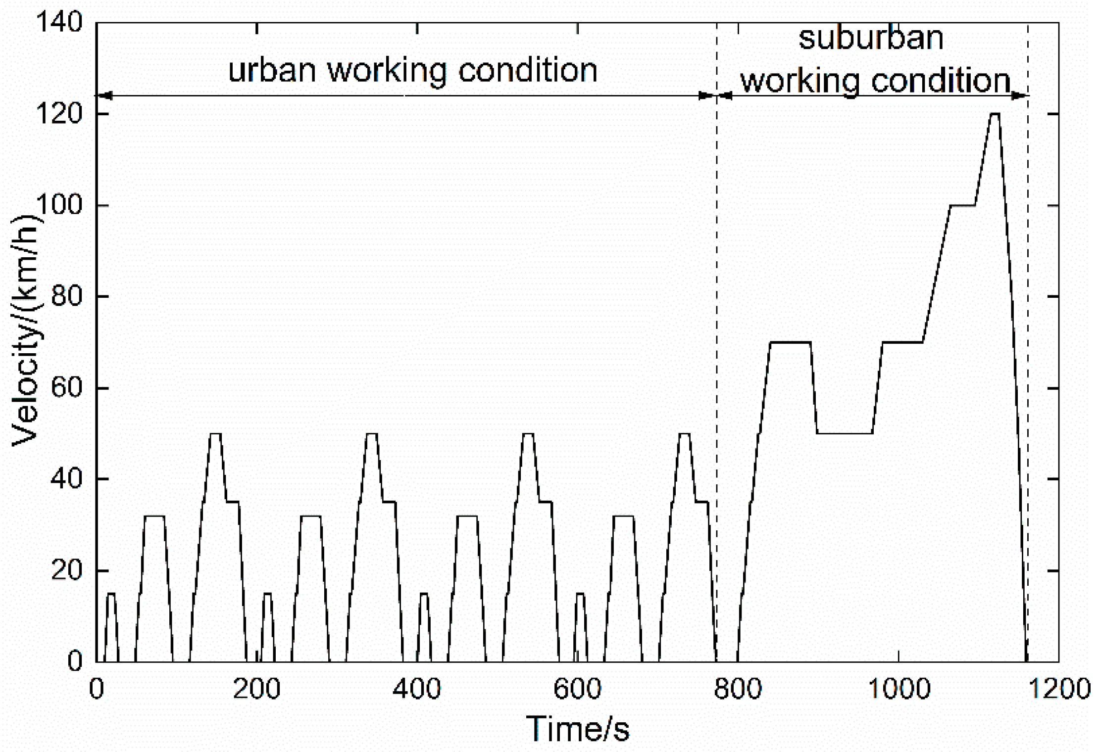
The test for determining the energy consumption of the PHEV was carried out under the NEDC, as shown in Figure 13.
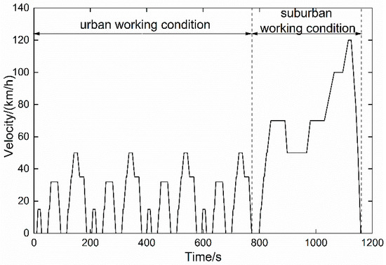
Figure 13.
New European drive cycle (NEDC) working conditions.
Here, the CD–CS energy management strategy was adopted. The CD strategy was adopted in the urban working condition, in which the tracking motor was only provided with the demand power of the vehicle. The CS strategy was adopted in the suburban working condition, in which the SOC of the battery remained the same before and after applying the working condition. In this condition, the mode division was also based on the rules given in Section 4.1.
5.2. Solution for Bi-Level Nested Component-Sizing Method
The GA is a global optimization random search algorithm simulating biological inheritance and evolution processes. It has proved to be an effective strategy to solve complex engineering optimization problems characterized by nonlinear, multimodal, and nonconvex objective functions.
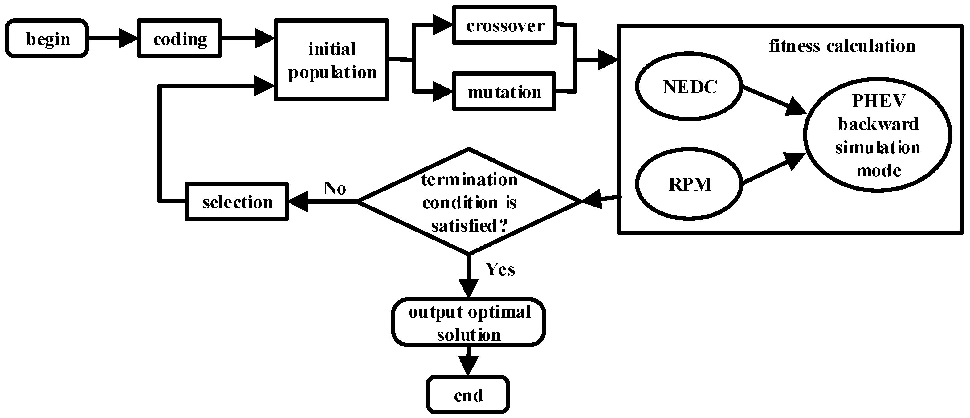
The specific optimization steps of this bi-level nested method for PHEV component sizing are shown in Figure 14.
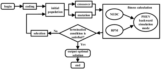
Figure 14.
Framework of the bi-level nested parameter optimization method.
- The optimization variables of the PHEV parameter optimization problem were converted into individuals in the genetic space, and then a group of initial populations was randomly generated in the feasible domain of the problem.
- The power components and transmission parameters represented by each individual in the population were replaced in the series-parallel PHEV backward simulation model, and the consumption of electricity in the urban driving cycle of NEDC was calculated. The optimal fuel consumption under the suburban driving cycle of NEDC was determined using the RPKM. The electricity consumption and the optimal fuel consumption were converted to the corresponding transportation costs to determine the suitability of each individual (the total operating cost of NEDC).
- The next generation of the population was selected according to the size of the fitness. The smaller the adaptability, the larger the probability of being selected; the individuals with large adaptability were eliminated in the process of evolution.
- Crossover and mutation operations of individuals in the new species group produced the next generation of individuals.
- Steps 2 to 4 were repeated until the termination condition was satisfied. At this time, the algorithm converged to the best chromosome, obtaining the optimal solution to the problem.
In this method, the backward simulation model of the PHEV was embedded into the GA program as a module. The inner layer calculated its adaptability according to the component parameters of the individual; the outer layer used the fitness of each individual according to the inner layer to continuously search and optimize parameters in the multidimensional parameter space, guaranteeing the global optimality of component-sizing results.
5.3. Component-Sizing Results
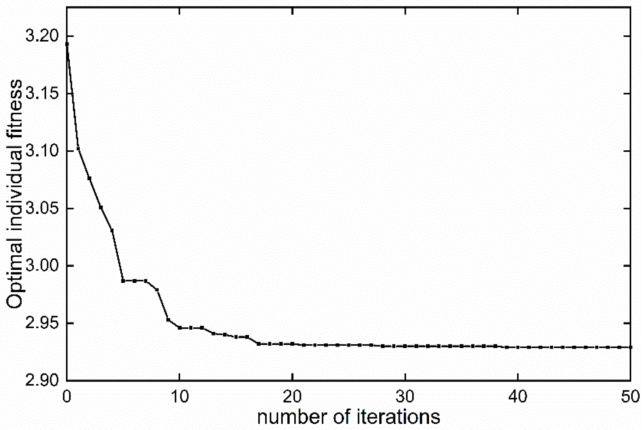
Figure 15 was developed based on the relationship between optimal fitness and iteration number after 50 iterations based on the GA and RPKM. When the fitness is small and remains unchanged, the optimal value of GA is considered to be the global optimal solution. It can be seen from Figure 15 that, when the iteration reached 20 generations, the fitness tended to be stable. At this point, we can assume that the parameters obtained by GA are the global optimal solution, that is, the optimal solution of component-sizing. This process took 16.7 h; however, if it were based on the GA and DP algorithm, it would require approximately hundreds of hours.
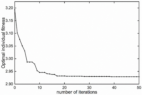
Figure 15.
Relationship between optimal individual fitness and number of iterations.
The result of parameter optimization presented in Table 4 can provide a reference basis for the selection of power system schemes for trial vehicles.
Table 4.
Parameter optimization results.
6. Conclusions
To solve the problem that the traditional DP algorithm and PMP algorithm have a long solution time or even cannot solve due to the complexity of the series-parallel PHEVs powertrain model, this paper proposes to use the Radau pseudospectral knotting method (RPKM) to solve the global-optimization-based energy management strategy of the series-parallel PHEVs to improve computational efficiency. A backward simulation model of the series-parallel PHEVs for optimal control was established, and the optimal control problem of energy management strategy was established. The optimal control problem was transformed into an NLP problem by using the RPKM. Simulation results showed that compared with DP algorithm, the global-optimization-based energy management strategy based on the RPKM improves the computational efficiency by 1806 times with a relative error of only 0.12%. Based on the high calculation efficiency of RPKM, a bi-level nested component-sizing method combining the GA and RPKM was developed. The results indicated that RPKM has lower computational cost and can provide optimization results for chief engineers of hybrid system more efficiently. Through the above research, the feasibility and superiority of RPKM applied to the global-optimization-based energy management strategy of the series-parallel PHEVs were verified.
Author Contributions
K.Z. proposed the energy management strategy and component-sizing method; J.B. and Z.L. built up the simulation model and programmed the algorithm; all authors conducted the experimental campaign and analyzed the data; J.B. wrote the original draft; K.Z. and Y.L. gave helpful comments and revised the paper.
Funding
This research was funded by the Foundation of Guangdong Provincial Natural Science grant number [2016A030313517] and the National Natural Science Foundation of China grant number [51575189].
Conflicts of Interest
The authors declare no conflict of interest.
Nomenclature
| instantaneous fuel injection rate of the engine, g/s | g | gravity constant, | |
| output torque of the engine, | f | rolling resistance coefficient | |
| minimum output torque of the engine, | i | slope of the road | |
| maximum output torque of the engine, | aerodynamic drag coefficient | ||
| output speed of the engine, r/min | A | frontal area of the vehicle, | |
| minimum output speed of the engine, r/min | δ | rotational inertial coefficient | |
| maximum output speed of the engine, r/min | vehicle speed, | ||
| working efficiency of the ISG motor | torque demand of the driving wheel, | ||
| output torque of the ISG motor, | tire effective radius, m | ||
| minimum output torque of the ISG motor, | output torque for mechanical brakes, | ||
| maximum output torque of the ISG motor, | total fuel consumption under the target driving cycle, g | ||
| output speed of the ISG motor, r/min | fuel consumption of the engine, g | ||
| minimum output speed of the ISG motor, r/min | distribution coefficient | ||
| maximum output speed of the ISG motor, r/min | α | penalty factor | |
| working efficiency of the tracking motor | β | oil-to-electricity conversion coefficient | |
| output torque for the tracking motor, | maximum output power of the power battery, kW | ||
| minimum torque for the tracking motor, | F | the sum of all motion resistance forces, | |
| maximum torque for the tracking motor, | m | vehicle mass, kg | |
| output speed of the tracking motor, r/min | nominal capacity of the power battery, As | ||
| minimum speed of the tracking motor, r/min | state of charge of the battery | ||
| maximum speed of the tracking motor, r/min | minimum allowable SOC values of the battery | ||
| open circuit voltage of the power battery, V | maximum allowable SOC values of the battery | ||
| terminal voltage of the power battery, V | output power of the APU, kW | ||
| current of the power battery, A | minimum output power of the APU, kW | ||
| internal resistance of the power battery, Ω | maximum output power of the APU, kW | ||
| output power of the power battery, kW | minimum output power of the power battery, kW |
Abbreviation
| APU | Auxiliary Power Unit |
| CD | Charge Depleting |
| CS | Charge Sustaining |
| DP | Dynamic Programming |
| ECMS | Equivalent Consumption Minimum Strategy |
| GA | Genetic Algorithm |
| HEV | Hybrid Electric Vehicle |
| ISG | Integrated Starter Generator |
| MPC | Model Predictive Control |
| NEDC | New European Drive Cycle |
| NLP | Non-Linear Programming |
| OCV | Open Circuit Voltage |
| PHEV | Plug-in Hybrid Electric Vehicle |
| PMP | Pontryagin Maximum Principle |
| RPKM | Radau Pseudospectral Knotting Method |
| SDP | Stochastic Dynamic Programming |
| SNOPT | Sparse Nonlinear OPTimizer |
| SOC | State of Charge |
| TM | Tracking Motor |
References
- Zhao, K.; Liang, Z.; Huang, Y.; Wang, H.; Khajepour, A.; Zhen, Y. Research on a Novel Hydraulic/Electric Synergy Bus. Energies 2017, 11, 34. [Google Scholar] [CrossRef]
- Tang, X.; Yang, W.; Hu, X.; Zhang, D. A novel simplified model for torsional vibration analysis of a series-parallel hybrid electric vehicle. Mech. Syst. Signal Process. 2017, 85, 329–338. [Google Scholar] [CrossRef]
- Abedi, S.; Alimardani, A.; Gharehpetian, G.B.; Riahy, G.H.; Hosseinian, S. A comprehensive method for optimal power management and design of hybrid RES-based autonomous energy systems. Renew. Sustain. Energy Rev. 2012, 16, 1577–1587. [Google Scholar] [CrossRef]
- Zeyu, C.; Rui, X.; Kunyu, W.; Jiao, B. Optimal energy management strategy of a plug-in hybrid electric vehicle based on a particle swarm optimization algorithm. Energies 2015, 8, 3661–3678. [Google Scholar]
- Yan, J. Multi-objective parameters optimization of electric assist control strategy for parallel hybrid electric vehicle. In Proceedings of the IEEE/ASME International Conference on Advanced Intelligent Mechatronics, Singapore, 14–17 July 2009. [Google Scholar]
- Sarvestani, A.S.; Safavi, A.A. A novel optimal energy management strategy based on fuzzy logic for a hybrid electric vehicle. In Proceedings of the IEEE International Conference on Vehicular Electronics and Safety, Pune, India, 11–12 November 2009. [Google Scholar]
- Xiong, W.; Zhang, Y.; Yin, C. Optimal energy management for a series-parallel hybrid electric bus. Energy Convers. Manag. 2009, 50, 1730–1738. [Google Scholar] [CrossRef]
- Khayyam, H.; Bab-Hadiashar, A. Adaptive intelligent energy management system of plug-in hybrid electric vehicle. Energy 2014, 69, 319–335. [Google Scholar] [CrossRef]
- Antonio, S.; Lino, G. Control of Hybrid Electric Vehicle-Optimal Energy Management Strategies. IEEE Control Syst. Mag. 2007, 4, 60–70. [Google Scholar]
- Gao, J.; Strangas, E.G.; Sun, F.; Zhu, G.-M.G. Equivalent fuel consumption optimal control of a series hybrid electric vehicle. Proc. Inst. Mech. Eng. Part D J. Automob. Eng. 2009, 223, 1003–1018. [Google Scholar] [CrossRef]
- Geng, B.; Mills, J.K.; Sun, D. Energy management control of micro turbine-powered plug-in hybrid electric vehicles using the telemetry equivalent consumption minimization strategy. IEEE Trans. Veh. Technol. 2011, 60, 4238–4248. [Google Scholar] [CrossRef]
- Zhang, S.; Xiong, R.; Sun, F. Model predictive control for power management in a plug-in hybrid electric vehicle with a hybrid energy storage system. Appl. Energy 2017, 185, 1654–1662. [Google Scholar] [CrossRef]
- Cairano, S.D.; Bernardini, D.; Bemporad, A.; Kolmanovsky, I.V. Stochastic MPC with learning for driver-predictive vehicle control and its application to HEV energy management. IEEE Trans. Control Syst. Technol. 2014, 22, 1018–1031. [Google Scholar] [CrossRef]
- Qian, L.; Qiu, L.; Xin, F.; Chen, P.; Wang, J. Energy Management Control Strategy and Optimization for Plug-in 4WD Hybrid Electric Vehicle. Trans. Chin. Soc. Agric. Eng. 2015, 31, 68–76. [Google Scholar]
- Yuan, Z.; Teng, L.; Sun, F.; Peng, H. Comparative Study of Dynamic Programming and Pontryagin’s Minimum Principle on Energy Management for a Parallel Hybrid Electric Vehicle. Energies 2013, 6, 2305–2318. [Google Scholar] [CrossRef]
- Patil, R.M.; Filipi, Z.; Fathy, H.K. Comparison of Supervisory Control Strategies for Series Plug-In Hybrid Electric Vehicle Powertrains Through Dynamic Programming. IEEE Trans. Control Syst. Technol. 2014, 22, 502–509. [Google Scholar] [CrossRef]
- Tribioli, L.; Barbieri, M.; Capata, R.; Sciubba, E.; Jannelli, E.; Bella, G. A Real Time Energy Management Strategy for Plug-in Hybrid Electric Vehicles based on Optimal Control Theory. Energy Procedia 2014, 45, 949–958. [Google Scholar] [CrossRef]
- Uebel, S.; Murgovski, N.; Tempelhahn, C.; Baker, B. Optimal Energy Management and Velocity Control of Hybrid Electric Vehicles. IEEE Trans. Veh. Technol. 2018, 67, 327–337. [Google Scholar] [CrossRef]
- Chen, Z.; Mi, C.C.; Xu, J.; Gong, X.; You, C. Energy management for a power-split plug-in hybrid electric vehicle based on dynamic programming and neutral networks. IEEE Trans. Veh. Technol. 2013, 63, 1567–1580. [Google Scholar] [CrossRef]
- Yu, H.; Kuang, M.; Mcgee, R. Trip-oriented energy management control strategy for plug-in hybrid electric vehicles. In Proceedings of the 50th IEEE Conference on Decision and Control and European Control Conference, Orlando, FL, USA, 12–15 December 2011. [Google Scholar]
- Peng, J.K.; He, H.W.; Xiong, R. Rule based energy management strategy for a series-parallel plug-in hybrid electric bus optimized by dynamic programming. Appl. Energy 2017, 185, 1633–1643. [Google Scholar] [CrossRef]
- Moura, S.J.; Fathy, H.K.; Callway, D.S.; Stein, J.L. A stochastic optimal control approach for power management in plug-in hybrid electric vehicles. IEEE Trans. Control Syst. Technol. 2011, 19, 545–555. [Google Scholar] [CrossRef]
- Bashash, S.; Moura, S.J.; Forman, J.C.; Fathy, H.K. Plug-in hybrid electric vehicle charge pattern optimization for energy cost and battery longevity. J. Power Sources 2011, 196, 541–549. [Google Scholar] [CrossRef]
- Zhang, Y.; Meng, D.; Zhou, M.; Lu, D. Management strategy based on genetic algorithm optimization for PHEV. Int. J. Control Autom. 2014, 7, 399–408. [Google Scholar]
- Serrao, L.; Onori, S.; Rizzoni, G. ECMS as a realization of Pontryagin’s minimum principle for HEV control. In Proceedings of the 2009 American Control Conference, St. Louis, MI, USA, 10–12 June 2009. [Google Scholar]
- Xu, K.; Qiu, B.; Liu, G.; Chen, Q. Energy management strategy design of plug-in hybrid electric bus based on Pontryagin’s Minimum Principle. In Proceedings of the 2014 IEEE Conference and Expo Transportation Electrification Asia-Pacific, Beijing, China, 31 August–3 September 2014. [Google Scholar]
- Hou, C.; Ouyang, M.; Xu, L.; Wang, H. Approximate Pontryagin’s minimum principle applied to the energy management of plug-in hybrid electric vehicles. Appl. Energy 2014, 115, 174–189. [Google Scholar] [CrossRef]
- Zhang, J.; Zheng, C.; Cha, S.W.; Duan, S. Co-state variable determination in Pontryagin’s Minimum Principle for energy management of hybrid vehicles. Int. J. Precis. Eng. Manuf. 2016, 17, 1215–1222. [Google Scholar] [CrossRef]
- Lin, X.; Sun, D.; Deng, T. Energy management strategy optimization for a series-parallel hybrid electric bus based on Pontryagin’s minimum principle. Automot. Eng. 2012, 34, 865–870. [Google Scholar]
- Du, C.; Gan, W.; Zhang, P. Comparison of torque distribution strategies with different optimization objective function for HEV based on dynamic programming. Appl. Res. Comput. 2017, 34, 1308–1310. [Google Scholar]
- Wang, X.M.; He, H.W.; Sun, F.C.; Zhang, J.L. Application study on the dynamic programming algorithm for energy management of plug-in hybrid electric vehicles. Energies 2015, 8, 3225–3244. [Google Scholar] [CrossRef]
- Peng, H.; Yang, Y.Q.; Liu, C.Y. An energy management for series hybrid electric vehicle using improved dynamic programming. IOP Conf. Ser. Earth Environ. Sci. 2018, 121, 052077. [Google Scholar] [CrossRef]
- Shen, C.Y.; Xia, C.Y. Optimal Power Split in a Hybrid Electric Vehicle Using Improved Dynamic Programming. In Proceedings of the IEEE Power & Energy Engineering Conference, Chengdu, China, 28–31 March 2010. [Google Scholar]
- Hung, Y.H.; Tung, Y.M.; Chang, C.H. Optimal control of integrated energy management/mode switch timing in a three-power-source hybrid powertrain. Appl. Energy 2016, 173, 184–196. [Google Scholar] [CrossRef]
- Silvas, E.; Bergshoeff, E.; Hofman, T.; Steinbuch, M. Comparison of bi-level optimization frameworks for sizing and control of a hybrid electric vehicle. In Proceedings of the Vehicle Power and Propulsion Conference, Coimbra, Portugal, 27–30 October 2014. [Google Scholar]
- Xiong, R.; He, H.; Sun, F. Methodology for optimal sizing of hybrid power system using particle swarm optimization and dynamic programming. Energy Procedia 2015, 75, 1895–1900. [Google Scholar] [CrossRef]
- Goos, J.; Criens, C.; Witters, M. Automatic Evaluation and Optimization of Generic Hybrid Vehicle Topologies using Dynamic Programming. In Proceedings of the 20th World Congress of the International-Federation-of-Automatic-Control (IFAC), Toulouse, France, 9–14 July 2017. [Google Scholar]
- Hernández, J.C.; Ruiz-Rodriguez, F.J.; Jurado, F. Modelling and assessment of the combined technical impact of electric vehicles and photovoltaic generation in radial distribution systems. Energy 2017, 141, 316–332. [Google Scholar] [CrossRef]
- Ruiz-Rodríguez, F.J.; Hernández, J.C.; Jurado, F. Probabilistic Load-Flow Analysis of Biomass-Fuelled Gas Engines with Electrical Vehicles in Distribution Systems. Energies 2017, 10, 1536–1558. [Google Scholar] [CrossRef]
- Xiong, R.; Zhang, Y.; He, H.; Zhou, X.; Pecht, M.G. A double-scale, particle-filtering, energy state prediction algorithm for lithium-ion batteries. IEEE Trans. Ind. Electron. 2018, 65, 1526–1538. [Google Scholar] [CrossRef]
- Zhou, W.; Zhang, C.; Li, J.; Fathy, H.K. A pseudospectral strategy for optimal power management in series hybrid electric powertrains. IEEE Trans. Veh. Technol. 2016, 65, 4813–4825. [Google Scholar] [CrossRef]


© 2019 by the authors. Licensee MDPI, Basel, Switzerland. This article is an open access article distributed under the terms and conditions of the Creative Commons Attribution (CC BY) license (http://creativecommons.org/licenses/by/4.0/).