Article

Overpressure Generation Mechanisms and Its Distribution in the Paleocene Shahejie Formation in the Linnan Sag, Huimin Depression, Eastern China

1
Key Laboratory of Petroleum Resource Research, Institute of Geology and Geophysics, Chinese Academy of Science, Beijing 100029, China
2
Institutions of Earth Science, Chinese Academy of Sciences, Beijing 100029, China
3
University of Chinese Academy of Sciences, Beijing 100049, China
4
School of Energy Resources, China University of Geosciences, Beijing 100083, China
5
Geological Science Research Institute, SINOPEC Shengli Oilfield Company, Dongying 257000, China
*
Authors to whom correspondence should be addressed.
Energies 2019, 12(16), 3183; https://doi.org/10.3390/en12163183
Submission received: 23 June 2019 / Revised: 5 August 2019 / Accepted: 15 August 2019 / Published: 20 August 2019

Abstract

:
The Linnan Sag is one of the main oil-producing units in the Huimin Depression, Eastern China, and the pore pressure gradients obtained from drill stem tests (DSTs) range from 9.0 to 16.0 MPa/km. Uncertainty about the origin and distribution of abnormally high pressures in the Linnan Sag has led to different interpretations of hydrocarbon accumulation and resource assessments, and it interferes with safe drilling. In the Linnan Sag, mudstone compaction curves are substantially affected by several non-compaction factors, and the normal trend of the compaction curve is difficult to determine. The determination of the origin and distribution of overpressure in the Linnan Sag is a challenge. In this study, the factors that may affect mudstone compaction—such as the shale volume, higher calcareous, and organic matter content—were carefully examined and processed. The pressures in the mudstones were estimated by the corrected mudstone compaction curves, which were compiled from acoustic, density, and neutron logs, and calibrated using DST and mud weight data. The log response–vertical effective stress and acoustic velocity-density crossplots were used to identify the mechanisms that generate overpressure. The comprehensive compaction curve shows that the mudstones in the overpressured layer exhibit clear disequilibrium compaction characteristics. The logging response crossplots demonstrate that those overpressured points were consistent with the loading curve. The findings suggest that, the fundamental mechanism resulting in overpressures is the disequilibrium compaction of thick Paleocene mudstones. Hydrocarbon generation and vertical transfer of overpressure may be the main unloading mechanisms, which corresponds to the overpressure points that deviate from the loading curves. Since organic matter cracking may occur in formations at depths greater than 4000 m (Ro > 1.0%), the contribution of hydrocarbon generation to overpressuring is expected to be limited. The transfer of overpressure through opening faults is therefore considered to be the main cause of higher overpressure in local sandstones. The overpressures in the mudstones are characterized by a gradual decrease from the center to the margin in the Linnan Sag. The pressure in the isolated sand bodies are generally similar to that in the surrounding mudstones, whereas it can be lower or higher when the overpressure in the sand bodies are vertically transferred by faults to other pressure systems. The results of this analysis provide an indication of the magnitude, mechanism, and distribution of overpressure in the Linnan Sag. This insight can be used to guide further exploration of the Linnan Sag and similar geological basins.

1. Introduction

Abnormally high pressures are frequently found in sedimentary basins. Overpressures delay the thermal evolution of organic matter [1], protect the reservoir quality [2,3], and play an important role in hydrocarbon migration [4]. The existence of overpressure can enhance the sealing capacity of the caprock, while if the overpressure exceeds the fracture pressure of the caprock, the seal may fail [5]. Meanwhile, overpressured reservoirs present higher technical requirements for safe, optimized and rapid drilling, and the development of overpressure can greatly improve petroleum recovery efficiency [6].
It is very important to understand the originating mechanisms of overpressures, geological affects and their efficiency to estimate the distribution of abnormal pressures in a basin, reconstruct pressure evolution histories, and predict the risks associated with drilling boreholes [7,8,9,10,11,12].
In the past few decades, significant progress has been made in research on the origins of overpressure [9,13]. Numerous mechanisms have been proposed for overpressure generation in sedimentary basins, and several important mechanisms have been quantitatively evaluated [8,10,14,15]. Overpressure mechanisms are typically classified into two separate and distinct types: disequilibrium compaction and fluid expansion or vertical transfer of overpressure [11,16,17]. However, of all of the proposed fluid expansions, only the generation of gas is considered to be able to produce high magnitude overpressures [11,15,18,19]. Disequilibrium compaction is a loading overpressure-generating mechanism [4,9,17], which is caused by rapid sedimentation rate of the basin (vertical stress increase) or lateral tectonic compression (horizontal stress increase). Unloading mechanisms of overpressure generation are defined as processes that reduce the effective stress acting on sediment, including gas generation, clay diagenetic processes, and pressure transfer by lateral or vertical fluid flow [4,9,11].
It is not possible to directly measure the pressure in mudstone because of its low permeability; therefore, indirect methods have been widely used in pressure research and prediction [20,21,22]. Geophysical measurements that reflect petrophysical properties associated with overpressures in sedimentary sequences—including sonic velocity (AC, Vp and Vs), bulk density (DEN), and resistivity (Rt)—have been routinely applied. Log data are typically used because they are accessible and reliable [20]. The petrophysical properties of overpressured sequences differ depending on the overpressure mechanisms, thus leading to different variations in the effective stress in overpressured sequences. Therefore, overpressure mechanisms can be identified by their different responses to loading and unloading processes [17,23,24,25,26,27]. Loading–unloading curves have been frequently used as effective tools for identifying pressure generation mechanisms [19,28,29,30].
Sediments are normally compacted during burial following the loading curve, in which porosity decreases as effective stress increases. However, when overpressures are generated by disequilibrium in compaction, compaction is impeded, resulting in deposits having abnormally high porosities. Disequilibrium compaction is generally associated with a lithostatic stress parallel pore pressure increase and, consequently, an effective stress that remains constant with burial. Therefore, on a porosity-vertical effective stress plot, sediments that have undergone disequilibrium compaction remain on the loading curve [17,20,22]. Sediments that first compact under normal hydrostatic pressure conditions, and subsequently become overpressured by fluid expansion or vertical transfer, follow an unloading curve. The increasing pore pressure causes the vertical effective stress to decrease. However, compaction is mostly an irreversible process, and unloading mechanism is only associated with a small change in porosity because of the slight elastic contraction of sediment grains. Thus, overpressures generated by unloading process follow a porosity-vertical effective stress path away from the loading curve [17,20,22].
A reliable and objective compaction curve is the basis for pressure estimation and for the validity of the logging response-effective stress to distinguish between overpressure mechanisms. The petrological and petrophysical characteristics of mudstones in different intervals were assumed to be similar to each other when compiling mudstone compaction curves [20,31]. However, the compaction trends of mudstone are always inconsistent with those of the underlying intervals due to the differences in the mineral composition, fabric, and pore fluid properties [32,33,34,35]. Furthermore, the logging responses of mudstone are affected by several non-compaction geological factors, such as faults, fractures, and hydrocarbon-bearing properties [36]. In addition, large fluctuations in mudstone log values always result from borehole conditions. All of these factors affect the reliability of overpressure mechanism identification and pressure estimation, and must be eliminated during compaction studies [33,35,37].
The Linnan Sag is a petroliferous secondary tectonic unit in the Huimin Depression, Bohai Bay Basin, China. According to the results of resources evaluation, the predicted reserves are 7.01 × 10⁸ t, and control reserves are 0.68 × 10⁸ t in the Linnan Sag. At present, the proven reserves are 0.35 × 10⁸ t, the proven rate in the Linnan Sag is only 4.56%. Thus, it is in the initial stages of exploration, and the prospect is bright [38]. Overpressures are widespread in the Shahejie Formation in the Linnan Sag [39,40]. The pressure distribution is complicated, and oil migration and accumulation seem to be closely related to overpressures [41]. Based on the analyses of the pressures in reservoirs and the log responses to the overpressure in mudstones, the hypothesized mechanisms that generate overpressure in the Linnan Sag include disequilibrium compaction, hydrocarbon generation, clay mineral dehydration, and aquathermal expansion [38,42,43]. However, the compaction curves of Paleogene mudstones in the Huimin Depression or even in the Bohai Bay Basin are too irregular to distinguish abnormalities from the normal compaction trend because the effects of non-compaction factors on compaction curves are underestimated [44,45,46]. Underestimating these factors causes errors in the identification of overpressure mechanisms and pressure prediction. Therefore, the understanding of the generation mechanisms, predictions of abnormal pressures, and the knowledge of hydrocarbon accumulation and the assessment of petroleum resources are still preliminary in the Linnan Sag [40]. In addition, well kicks and gas intrusions during drilling are common because of the inability to accurately predict overpressure. Thus, identifying the characteristics of abnormal pressures, confirming the mechanisms, and accurately predicting the overpressure distribution are important topics in the Linnan Sag.
In this article, based on measured pressure data obtained from drill stem tests (DSTs), the authors summarize the reservoir pressure characteristics in the Linnan Sag, and attempt to eliminate the factors that affect the similarity of the mechanical compaction of different Paleogene mudstones. The characteristics of the mudstone compaction and overpressure were analyzed, and the mechanisms of abnormal pressure were discussed by combining the acoustic velocity–vertical effective stress and density crossplots. Finally, the migration, accumulation, and exploration implications of the overpressure were discussed.

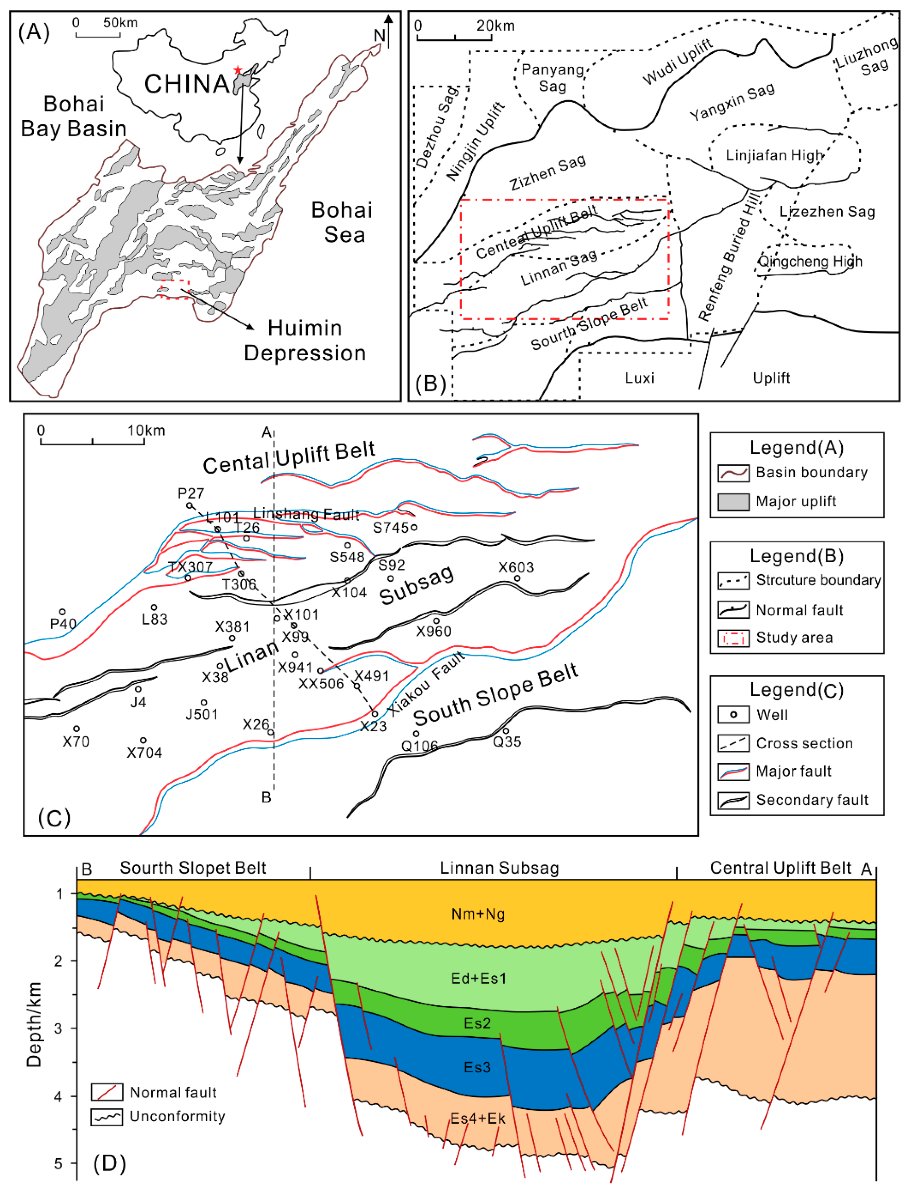
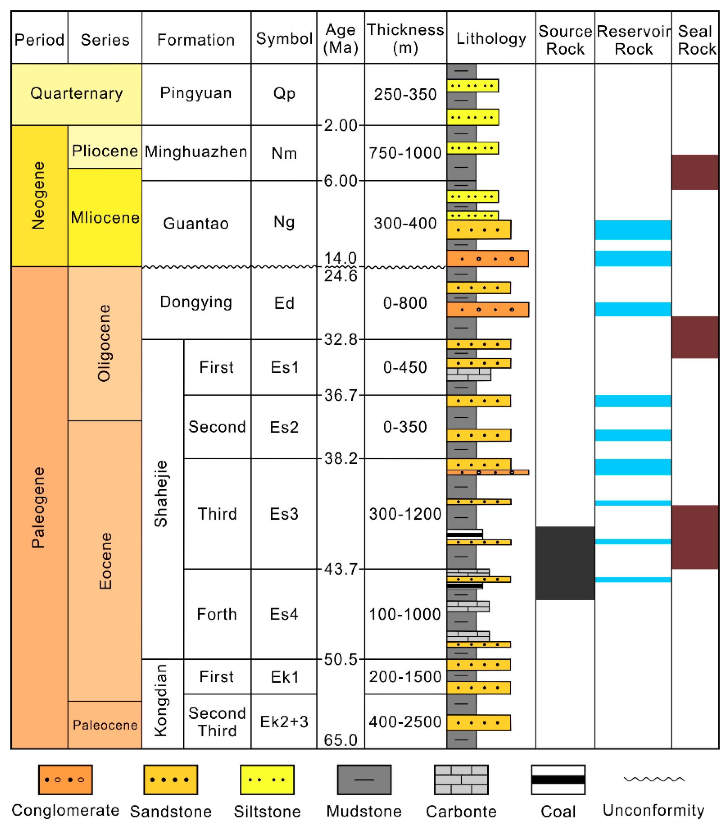
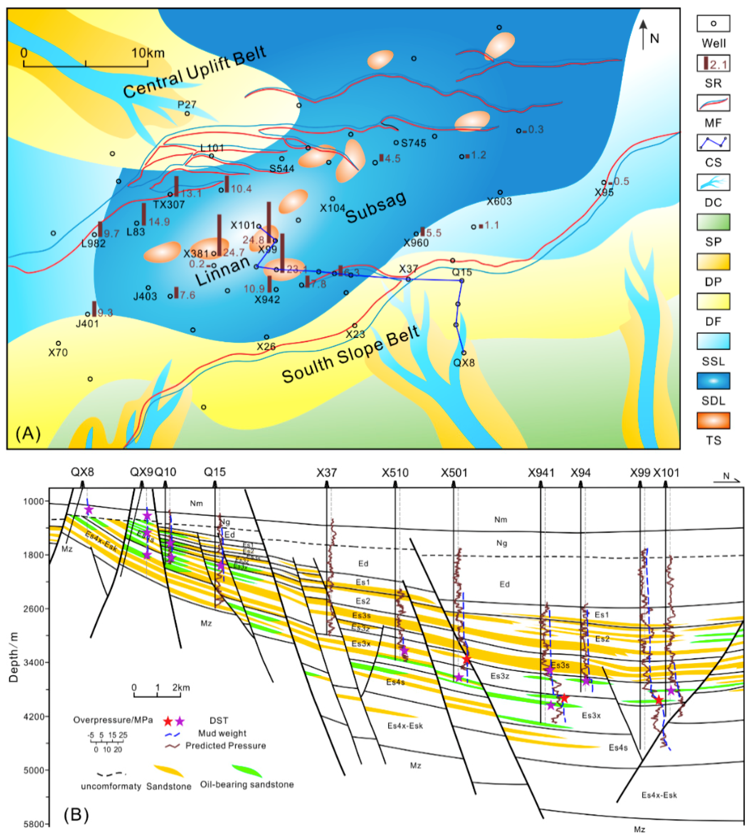
2. Geological Setting

The Huimin Depression, which is the largest secondary depression in the southwestern Jiyang Subbasin of the Bohai Bay Basin, eastern China, is a Mesozoic–Cenozoic rifted basin (Figure 1A). The Huimin Depression is bounded to the north by the Ningjin Uplift and the Wudi Uplift and to the south by the Luxi Uplift. To the west, it transitions into the Xinxian Depression, and it is connected to the Dongying Depression to the east (Figure 1B). The Linnan Sag is a secondary tectonic unit in the southwestern part of the Huimin Depression and is believed to be the main oil source kitchen in the Huimin Depression. Faults are well developed in the Linnan Sag, and the major faults generally trend NNE or NE. The Linnan Sag is controlled by the Xiakou Fault and the Linshang Fault, forming an asymmetric NE–SW-trending half-graben (Figure 1C,D). Some of oil source faults connect the source rocks and the reservoir and control the formation and distribution of oil traps and hydrocarbon accumulation zones [47,48].
The Linnan Sag is divided into three structural units: the Central Uplift Belt, the Linnan Subsag, and the South Slope Belt from north to south (Figure 1C,D). The Cenozoic tectonic activities in the Linnan Sag can be classified into five stages [49]: the initial rifting stage (60.5–50.5 Ma), the sustained rifting stage (50.5–43.7 Ma), the intense rifting stage (43.7–36.7 Ma), the continuous rifting stage (36.7–32.8 Ma), and the rifting-subsiding stage (32.8–24.6 Ma). The sag was uplifted during the Dongying movement (24.6–14.0 Ma) [50], which produced the unconformity between the Paleogene and Neogene sequences. Then, the Linnan Sag was completely transformed into a subsiding basin, which all formations are currently buried at the maximum burial depth.
The Cenozoic stratigraphic sequence in the Linnan Sag includes the Paleogene Kongdian Formation (Ek), Shahejie Formation (Es), and Dongying Formation (Ed); the Neogene Guantao Formation (Ng) and Minghuazhen Formation (Nm); and the Quaternary Pingyuan Formation (Qp) (Figure 2). On the basis of log characteristics and paleontological data analysis, the Shahejie Formation is divided into four members, which are denoted by Es4, Es3, Es2, and Es1 from the bottom to the top. The fourth member of the Shahejie Formation (Es4) developed locally, and has a thickness of less than 1000 m. the Es4 is mainly composed of aubergine mudstones intercalated with brown siltstone and sandstone, and it is further divided into the bottom part (Es4x) and the top part (Es4s). A semi-deep and deep lacustrine deposition system developed extensively in the third member of the Shahejie Formation (Es3), which has a thickness that ranges from 300 to 1200 m. Large sets of dark mudstone, shale, and oil shale deposits are locally interbedded with lenticular sandstone in the Es3, which can be further divided into the bottom part (Es3x), the middle part (Es3z), and the top part (Es3s). Deep-water slumping deposits developed frequently at the root of the delta front slope in the center of the sag, in which turbidite sandstones are widely distributed [51].
Sets of well-developed source-reservoir-seal assemblages exist in the Linnan Sag. The source rocks are mudstones and oil shales in Es4s and Es3x, and the extensively distributed Es3x is the predominant source rock with the greatest thickness. The Es3x source rock is rich in organic matter, and the kerogen types are primarily types I and II; and it is in the middle mature to the mature stage [52]. The reservoirs are composed mainly of Es4, Es3, and Es2 clastic reservoirs, and the lithologic assemblages are conglomerate, glutenite, sandstone, and siltstone. The main facies types include delta plain distributary channels, delta front underwater distributary channels, and estuary dams [53]. The caprocks are mainly deep-lacustrine shale and lacustrine mudstone [53].

3. Data and Methods

3.1. DST Data Selection

In oil exploration wells, fluid pressure profiles are rarely run, and pressures are mostly derived from drill stem tests (DST). The reservoir pressures in wells have been extracted from reports of DST results measured by Shengli Oil Company (SINOPEC). DST are performed by isolating an interval of the borehole and allowing fluid to flow into the test apparatus, and are normally conducted through the perforated casing to simplify depth interval selection and isolate the formations. Packers are set above and below the target zone, and if the packers do not fail, then the DST measurements apply to that specific open zone between the packers [54]. A complete DST measurement includes several stages, including the initial flow, initial shut-in, final flow, and final shut-in. The critical is the final shut-in pressure, which should be the formation pressure when the shut-in time after flow testing is sufficiently long and the permeability of the open interval is high enough. In fact, the final shut-in pressure is a noisy dataset and, the most common cause of the error is incomplete pressure recovery due to either local mud-cake problems or inherently low permeability of the formation [54]. Therefore, the measured pressure data should be screened, and the obviously unreliable data should be rejected.
We used the following criteria to determine whether a DST value is valid: (1) consistency with comparable tests, such as repeat formation test (RFT) and modular formation dynamics test (MDT); (2) comparable pressures at the ends of the initial and final shut-in periods (within 10%); (3) comparable flowing and shut-in pressures; (4) a skin factor of less than 0; and (5) the DST data from development wells are removed. Although none of these criteria is definitive, a DST value was considered valid when 3–4 of the criteria were met.
A total of 353 DST data points were obtained from 217 wells in the Linnan Sag, 18 DST points from development wells, and 31 points with incomplete pressure recovery were excluded from the analysis through detailed screening of the DSTs. After the validity check, 304 valid DST data points from 188 wells were finally selected to investigate the characteristics of overpressure in the Linnan Sag.

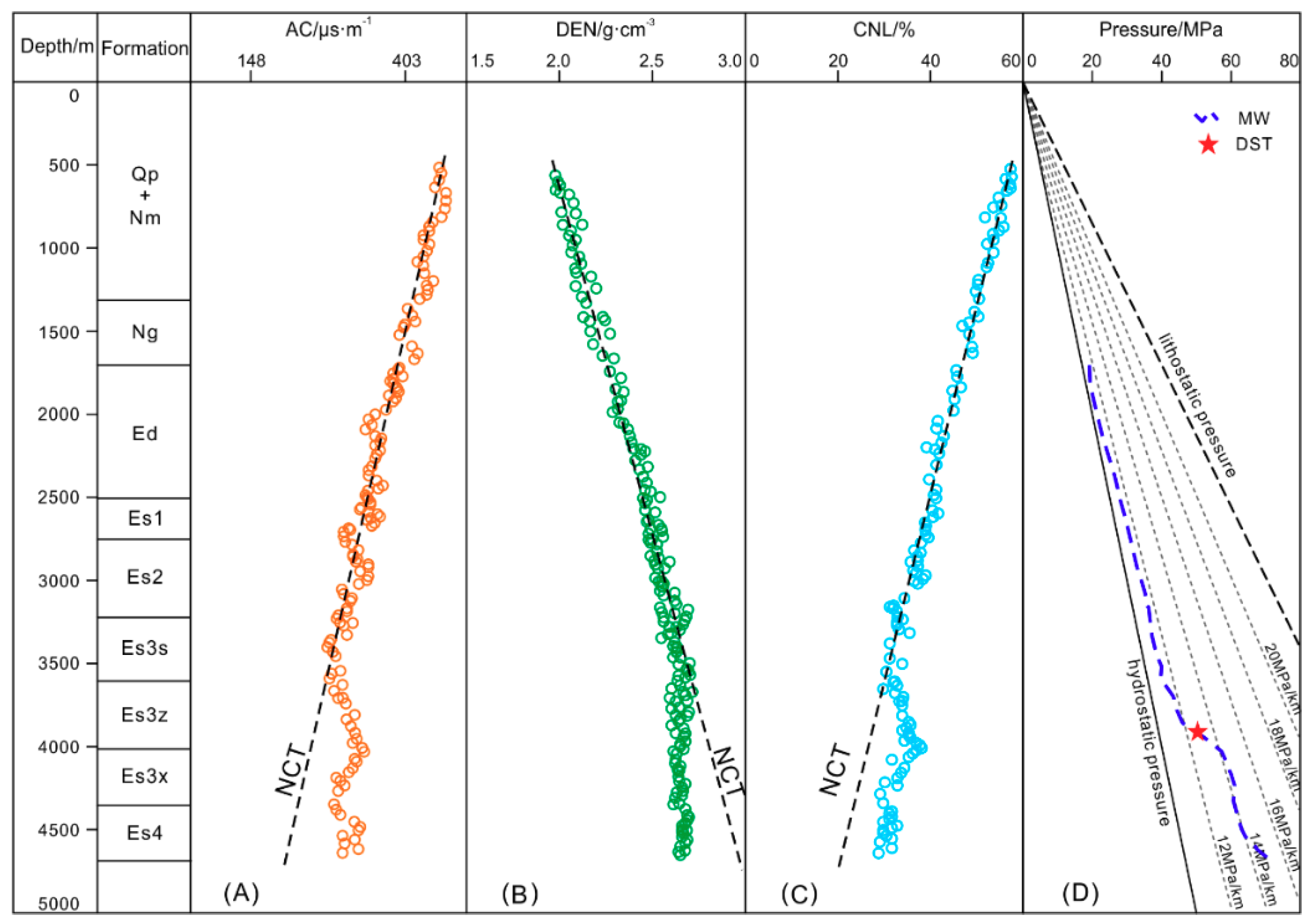
3.2. Well Log and Compaction Curve

Pressure has never been measured in a mudstone; therefore, the limited test data were supplemented with electronic logs to predict and analyze the pressures in the wells. Well log datasets from 68 wells drilled to the third member of the Shahejie formation (Es3) in the Linnan Sag were acquired from Shengli Oil Company (SINOPEC). The available wells were selected based on the availability of information about the formation and the log data sheets covering the overburden sediments. The log data used in this study included gamma-ray, acoustic, density, resistivity, neutron, and caliper logs. Compaction curves directly compiled from the log data in the Linnan Sag are irregular, and the normal compaction trend is always difficult to determine. The effects of various geological factors must be eliminated to ensure that the properties of the mudstones in the target interval and the overlying interval are similar [33].
The log data were checked and corrected for the environmental conditions, and the quality of the log data was further scrutinized to filter out erroneous readings. In the shallow intervals, the low cementation and unconsolidated formations are frequently subjected to borehole sloughing, which leads to unreliable logging results. Significant deviations from the overall trends were removed, especially at the beginning of the logging runs. In the process of drilling holes, hole-wall collapsing and hole enlargement occur, leading to unavoidable effects on the acoustic time and density logging value. Borehole collapse and rough sidewalls result in changes in acoustic transmission in the well. The acoustic log may be larger than the real values of formation. The plate of the logging tools cannot be in close contact with the well wall because of the borehole enlargement; as a result, the density recorded by the logging instrument will not reflect the formation properties, but the representation of the drilling mud in the well. Intervals with poor borehole conditions were identified by comparing the logged caliper values with the bit diameters, and data showing inconsistencies in this comparison were generally excluded. Breakpoint descriptions from unpublished reports indicate the depths of faults, and the log responses in the fault zones, which have higher acoustic velocities and lower densities, were also excluded.
The lithology, which was determined by cutting sample descriptions for each well and calibrated with the shale volume (Vsh) calculated from the gamma-ray logs with a cut-off of 75%, was applied to differentiate the mudstone-dominated units from other lithologies to ensure that the mineral compositions were similar to the greatest extent possible. To reduce the impact of the surrounding rock on the logs, the target mudstone interval was generally more than 5 m thick, and average values of the acoustic, density, and neutron logs were obtained. The data points influenced by carbonate cementation in the Es1 were identified by higher their resistivity and velocity values. Anomalously high gamma-ray and acoustic values were indicative of organic-rich shales or carbargilite in the Es3 and Es4; all of these log data were excluded from further analysis. The log data were used directly, rather than converting them to porosity, to prevent the introduction of additional uncertainties.
According to the DST data and the equivalent pressure converted from the mud weight, 38 wells with overpressure and 30 wells with normal pressure in the Linnan Sag were selected for further study. The acoustic (AC), density (DEN), and neutron (CNL) log data from the mudstone sections were used to draw comprehensive compaction curves. Figure 3 shows the compaction curves in a representative well (X99): the mudstone is normally compacted above 3600 m, and the acoustic and neutron log values gradually decrease with depth, whereas the density increases. All three logs exhibit no anomalies with depth. The curve in the mudstone of well X99 deviates from the normal compaction trend below approximately 3600 m, which illustrates that the acoustic and neutron log values are higher than the values for the normal compaction trend (NCT), whereas the density is lower than that in the NCT at the same depth. The uniformly deviating well log curves reflect the pronounced overpressure in the mudstones (Figure 3). The log responses match the overpressure well, and the top of the overpressured zone can be interpreted at 3600 m, which is consistent with the compaction curves (Figure 3).

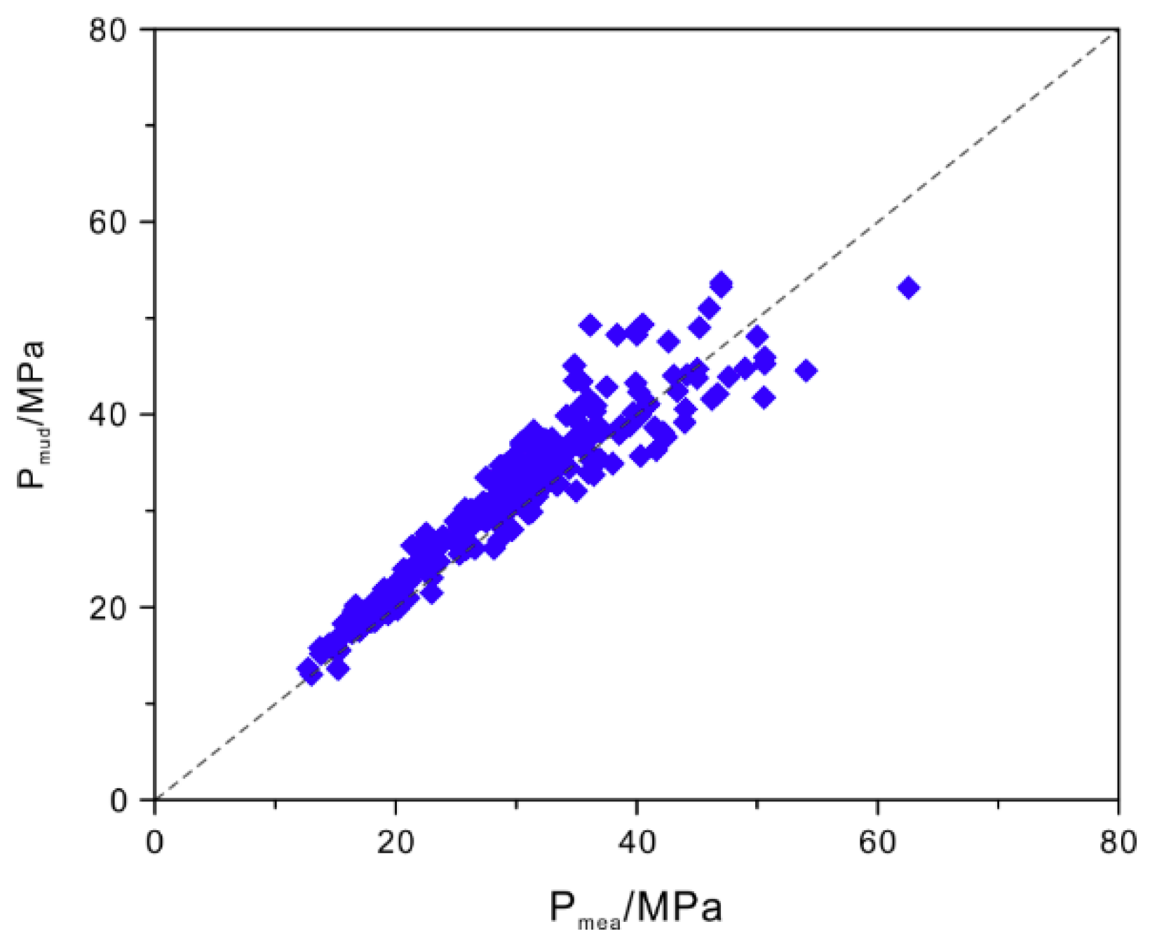
3.3. Mud Weight and Equivalent Pressure

DST can only obtain the formation pressure of permeable units that are perforated in particular depth, in order to compensate for the discrete and limited DST pressure data, the mud weight in the boreholes, where balanced or underbalanced drilling technology was used, may be taken into account [55]. This drilling technology has been applied extensively in the Linnan Sag, so the mud weight values can be considered as a type of direct pressure data when they are calibrated with DST data.
The mud weight ρmud can be converted to equivalent pressure Pmud as follows [56]
Pmud = ρmud·g·H
where Pmud is the pressure, MPa; H is the depth, km; g is the acceleration due to gravity, 9.8 m/s2; and ρmud is the mud weight, g/cm3. The values computed using (1) are plotted against depth for comparison with the other pressure measurements.
There is good agreement between the DST data and the mud weight equivalent pressure at the corresponding depths (Figure 4), indicating that the mud weight equivalent pressure can be used to represent the formation pressure in the Linnan Sag.

4. Pressure Characteristics and Origins of Overpressure

4.1. Pressures in Reservoirs

In actual operations, DST pressures are generally considered to be normal pressures (hydrostatic pressures) when the values fall into a pore pressure gradient interval from 9.0 to 11.0 MPa/km [11].
In Figure 5, all of the suitable DST pressure values are plotted on three graphs with pressure as the abscissa and depth as the ordinate to show the vertical overpressure distribution versus depth, depending on the stratigraphy. The results show that most of the measured pressures in the Shahejie Formation in the Linnan Sag are normal, and approximately 20% of the pressure values are indicative of overpressures (Figure 5). The pressures in the Es2 and Es1 are shown in Figure 5A, which indicates that the pressures in these layers are normal pressures (Figure 5A). The fluid pressures in the Es3 and Es4 are different above and below 3000 m. The fluid pressure system in the upper region is mainly hydrostatic, whereas the pressures in the lower region appear to be more complicated. The pressure data show the coexistence of abnormally high pressure and hydrostatic pressure in the same layers. The overpressured section in Es3 is concentrated at 3000–4300 m, and the overpressures are 0–24 MPa (Figure 5B). The overpressures in Es4 vary from 0 to 14 MPa and mainly occur at approximately 3000–4000 m (Figure 5C).

4.2. Pressures in Mudstones

The overpressure in mudstones can be estimated by standard porosity-based pore pressure prediction techniques, such as equivalent depth method, which mainly represents the overpressure generated by disequilibrium compaction [22,31,57].
Figure 6 presents the pressures in the mudstones on the profiles corresponding to three wells. Well P27 is located in the uplift, and the estimated pressures reveal normal pressures without overpressure (Figure 6A). The estimated pressures show that the top of the overpressured zone is at a depth of approximately 3300 m in the upper part of Es3z in well XX506 (Figure 6B). The overpressures then increase with depth, and the excess pressures vary from 3 to 11 MPa. The top of the overpressured zone is deeper in well X99 (Figure 6C) at approximately 3600 m in the middle of Es3z. The estimated pressures generally increase with depth, but the excess pressures decrease toward the boundary of Es3x and Es4s in both beds. The estimated excess pressures vary from 5 to 24 MPa.

4.3. Correspondence of Pressures between Reservoirs and Adjacent Mudstones

The mudstone overpressures in Es3 are the characterized by a gradual decrease from the center to the margins in the Linnan Sag, and this phenomenon is generally consistent with the strike of the sag. The area of wells X99–X381 is the center of the anomalous pressures, which is also the depocenter. The largest overpressure exceeds 20 MPa, and the overpressures decrease gradually from the center of the sag to both the north and south and approach hydrostatic pressure in the uplift within the Linnan Sag (Figure 7).
The reservoir pressure in isolated sand bodies is transferred from the adjacent overpressured mudstones; thus, the pressures in the mudstones are generally equal to those in the reservoir units. For example, in well X99, there is good agreement between the estimated and measured pressures (Figure 8A). The estimated pressure is approximately equal to the mud weight in well X381. However, there are a few discrepancies between the reservoir and mudstone pressures. The measured pressure is higher than the predicted pressure (Figure 8B), which indicates a contribution of fluid expansion or vertical transfer to the overpressure. In addition, the reservoir pressure is less than the estimated pressures in the adjacent mudstones; for example, in well X38, the estimated pressure matches the mud weight well but is higher than the measured pressure (Figure 8C), which indicates that the reservoir pressure may be dissipated by connected sand bodies or opening faults [12,58].

4.4. Identifying the Overpressuring Mechanisms

Loading–unloading curves defined by acoustic velocity–vertical effective stress plots are widely accepted to distinguish the mechanisms of overpressure [11,17]. The origin of overpressure can be identified as disequilibrium compaction if the overpressured points lie on the loading curve and, as fluid expansion or transfer processes if the overpressured points lie off the loading curve [17,23].
The vertical effective stress in the area was calculated using the vertical stress determined from density logs and pore pressures measured from the DSTs. The acoustic velocity corresponding to each DST testing point was taken as the average value of the mudstones within the interval of the DST point. Overall, 216 sets of acoustic velocity and vertical effective stress values were obtained from 134 wells in the Linnan Sag. Among them, 181 DST tests indicated normal pressure (<11.0 MPa/km) and were used to establish the loading curve. The loading curve is more concentrated due to eliminating the effect of factors that interfere with the similarity of mudstone properties, which provide a good foundation for further distinguishing the cause of the unloading mechanism (Figure 9).
The loading curve was used as a datum baseline, which was used to identify possible overpressure generating mechanisms. It can be seen in Figure 9 that 28 of the 35 overpressured velocity–vertical effective stress values lie within the scatter of the normal pressure points that define the loading curve. Therefore, the overpressures were generated by disequilibrium compaction. However, only 7 of the 35 overpressured data points deviate from the loading curve, which is consistent with the trend of the unloading curve, indicating the typical characteristics of fluid expansion or transfer processes. It is clear that the pressure gradient of the data that lie on the unloading curve is greater than 13.0 MPa/km (Figure 9), and the depths of these points vary from 3800 to 4300 m (Table 1).
Crossplots of acoustic velocity and density in overpressured mudstone may also be used as an effective method for distinguishing between disequilibrium compaction and fluid expansion or vertical transfer [28,59,60].
Figure 10 shows the acoustic velocity–density crossplots from three typical wells, which clearly distinguish the two types of overpressuring mechanisms. Figure 10A shows the results from well X99, where the top of the overpressured zone is at a depth of approximately 3600 m. The data above 3600 m illustrate typical loading characteristics, and the densities are generally less than 2.65 g/cm3. Between 3600 and 4100 m, the mudstones are overpressured, and the acoustic–density crossplot points lie predominantly on the loading curve, indicating that the overpressures are generated by disequilibrium compaction. Furthermore, the densities of the overpressured mudstones at depths greater than 4100 m become stable at 2.64–2.65 g/cm3, whereas the acoustic velocities decrease sharply, indicating overpressures that were generated by both disequilibrium compaction and fluid expansion or vertical transfer (Figure 10A). Similarly, the acoustic velocity–density crossplot for well X381 shows characteristics of the coexistence of disequilibrium compaction and fluid expansion or vertical transfer at depths greater than 3900 m (Figure 10B). However, for well X960, the maximum depth is approximately 3500 m, and the velocity–density crossplot shows that all of the overpressure points plot on the loading curve, which indicates that the overpressures are only generated by disequilibrium compaction (Figure 10C).

5. Discussion

5.1. Establishing a Reliable Mudstone Compaction Curve

The relationship between the mudstone porosity/log response and the effective stress has been widely used to distinguish the mechanism of generating overpressure. The assumption was that similar compaction processes operate in the normally and abnormally compacted mudstones [20,22,23,31]. The porosity/log response–effective stress relationship in the normally compacted mudstones can be used to evaluate that in abnormally pressured intervals [23]. However, the compaction trends of mudstones in different intervals differ due to the differences in the mineral composition, clay/calcareous/organic matter content, clay mineral fabric, and fluid properties [32,33,34,35,61]. This phenomenon is prominent in the post-Paleozoic sedimentary strata in the Bohai Bay Basin, where the study area is located [36].
In previous studies, mudstones were identified from wireline logs using the gamma-ray log as a lithological indicator (Vsh > 50%). The log data were then processed by the applying of a moving average filter with a smoothing interval of 50–100 m, and the compaction curve was used to analyze pore pressure. This type of workflow appears to be valid for marine mudstones with relatively uniform lithologies and a simple tectonic evolution [62,63,64]. However, the frequent lateral and vertical lithological changes in continental basins may significantly affect the log values, which are reflected by the variations in the compaction curves [44,45,46]. For example, a layer with higher carbonate and evaporite contents will cause the mudstone acoustic data to deviate to lower values, whereas organic-rich formations will exhibit abnormally high acoustic values [35]. In addition, faults/fractures and unconformities cause fluctuations in the compaction curves. All of these factors make the compaction curve trends more ambiguous and make it difficult to identify the top of abnormal compaction [33,37], which has led to multiple interpretations in mudstone compaction research and pressure analysis [29,30]. During this study, many factors that affect the mudstone log response were identified. The mudstone compaction curve should be more robust after eliminating all of the non-compaction factors that affect the compaction process and the similarity of the mechanical compaction between different Paleogene layers.
Figure 11 compares the mudstone compaction curves before and after the elimination of influencing factors. Before the elimination, the acoustic–depth relationship is scattered, and abnormally high values may occur locally, which previously led to interpretations of mudstone disequilibrium compaction. The results show that abnormally high acoustic values are actually due to the expansion of the borehole and the influence of organic matter (Figure 11A). A cut-off of 75% Vsh was applied to identify the mudstone-dominated units to ensure that the mineral compositions are similar to the greatest possible extent. This is supported by the XRD results, which indicate that the mineral compositions of mudstone exhibit little variation at different depths in the Linnan Sag [65]. Abnormal logging responses that are effected by borehole enlargement, organic matter, and carbonate cementation were excluded. When these effects were eliminated, the concentrated compaction curve was obtained, and the results show that disequilibrium compaction mainly occurs in the Es3z and underlying intervals (Figure 11B). Nevertheless, we attribute the lateral fluctuations in the compaction curves of the normal compaction trend to lithological and mineral variation (Figure 11B). On the basis of the log responses, the mechanism of abnormal pressure can be interpreted and pressure can be estimated.

5.2. Mechanisms of Overpressuring

The mechanisms of overpressuring in the mudstones in the Linnan Sag have been the subject of a long dispute [38,39,42,43]. Disequilibrium compaction of mudstone has generally been considered to be the most important cause of overpressuring, but other factors may also play important roles [40]. The analysis and understanding of the causes of overpressure presented in this paper may help to solve this problem.

5.2.1. Mudstone Disequilibrium Compaction

Under conditions of slow burial, normal compaction of sediments occurs; that is, the equilibrium between overburden and reducing pore-fluid volume is maintained, and the pore pressure keep hydrostatic. When thick sequences of clay-rich sediment undergo rapid burial, overpressure is generated because pore fluid cannot escape rapidly enough through the low-permeability overburden for the pore pressure to remain in hydrostatic equilibrium. Consequently, the sediment retains greater porosity than it would have if the pore pressure were hydrostatic. This mechanism of overpressure generation is known as disequilibrium compaction, and it is one of the most commonly observed mechanisms of abnormal pressure generation in sedimentary basins [8,9].
Conditions that favor disequilibrium compaction are rapid burial, high clay content, and low permeability. Disequilibrium compaction is therefore likely to be found in thick clay, mud, and shale successions during continuous rapid burial [66,67]. The disequilibrium compaction of mudstone begins in the Es3z in the Linnan Sag, which is dominated by lacustrine sediments, and the corresponding depth of the disequilibrium compaction coincides with the top of the overpressure. The geological conditions of the sedimentation in the Linnan Sag appear to be conducive to the occurrence of disequilibrium compaction.
The Es3 and Es4 of the Linnan Sag consist primarily of a thick set of mudstones with a maximum thickness that exceeds 1000 m, and they have experienced continuous rapid burial since the Miocene; however, the sedimentation rates vary in different locations. The maximum sedimentation rate occurred at the center of the Linnan Sag, in which the rate for Es4 and Es3 was greater than 300 m/Ma, and the rates for the overlying strata exceeded 200 m/Ma (Figure 12). Such high sedimentation rates coupled with the thick mudstone sequences resulted in favorable conditions for disequilibrium compaction. The sedimentation rates in the marginal zones are slightly lower and vary from approximately 200 m/Ma to 100 m/Ma for Es3 and Es4, respectively (Figure 12). In addition, the number and thickness of the sandstone interlayers also gradually increase toward the margins of the sag, which is not conducive to the occurrence of disequilibrium compaction in the margins. As a result, the slopes of the normal compaction trends decrease from the center to the margin (Figure 12), which indicates that the mudstone is more vulnerable to expelling water and that the conditions are not conducive to disequilibrium compaction [20,36]. Thus, the amplitude of disequilibrium compaction of the mudstone decreases, and the overpressure generated by disequilibrium compaction also decreases toward the margin. In the margin of the sag, mudstone is mostly normally compacted, and pore pressure remains hydrostatic.
The mudstone compaction curves in the Linnan Sag demonstrate that in the normally pressured sequences, acoustic, neutron, and density logs may clearly reflect the normal compaction (Figure 3 and Figure 12). However, in the overpressured zone, the acoustic and neutron logs exhibit abnormally higher values than the normal compaction trend, whereas the density tends to decrease or to stop increasing (Figure 3). The uniformly deviating well log curves reflect the clear characteristics of disequilibrium compaction [21].
The results of the acoustic velocity–vertical effective stress analysis also suggest that disequilibrium compaction is the primary mechanism for overpressure in the Linnan Sag (Figure 9). For most overpressure points, the acoustic velocity–vertical effective stress values are expected to plot on the loading curve. The acoustic velocity–density crossplots provide further evidence that most of the overpressure data fall on or near the loading curve, indicating overpressure generated by disequilibrium compaction (Figure 10).

5.2.2. Maturation of Organic Matter

Hydrocarbon generation may induce fluid expansion in mudstones and result in increased pressure. The magnitude of overpressure produced by kerogen maturation depends upon the kerogen type, abundance of organic matter, and thermal maturity [9,15].
Gray and black organic-rich mudstones and shales of Es3x and Es4s are widely distributed in the Linnan Sag. The total organic carbon content (TOC) of the Es3x source rocks varies from 0.41% to 7.1% with an average value of 1.55%. The chloroform bitumen “A”, which is the chloroform extract of the source rock, and used to evaluate the quality of source rock, ranges from 0.02% to 1.61%, with an average of 0.42%. The total hydrocarbon content (HC) is between 44.9 and 58.0 mg/g with an average of 50.7 mg/g. The quality of the source rock becomes poorer from the center toward the slope zone, with types I and II1 kerogen predominating in the center of the sag, and mainly type II2 existing in the slope zone [68]. Compared with the quality of the source rock in Es3x, the quality of that in Es4s is poorer, with an average TOC of 1.25%, chloroform bitumen “A” of 0.17%, and HC of 30.7 mg/g; the kerogen type is mainly type II [68].
The vitrinite reflectance (Ro, %) increases exponentially with burial depth, with maturity ranging from 0.40% to 1.20% (Figure 13). The hydrocarbon generation threshold is approximately 2500 m (Ro = 0.50%), and corresponding temperature is approximately 95 °C. When the depth is greater than 3500 m, Ro is generally greater than 0.80%, which indicates higher maturity and hydrocarbon generation potential, and the corresponding temperature is approximately 120 °C. When the burial depth reaches 4000 m, the Ro value approaches 1.0%, which is the peak of liquid hydrocarbon generation and corresponds to a temperature of approximately 140 °C.
The burial and thermal histories of the sediments in the Linnan Sag were reconstructed. Figure 14 illustrates the burial histories, the evolution of temperature and the maturation of organic matter on the profile of well X99. The source rock in the Es3x began to generate oil approximately 35 Ma (Ro: 0.5–0.7%) at a temperature of 97 °C. The oil generation is presently at its maximum degree at a temperature of 145 °C (Ro: 1.2%), with remaining in the liquid hydrocarbon generation window (Figure 14B). The evolution of oil generation at the bottom of the Es3x source rock shows three phases: the first phase of pyrolysis of the source rock was approximately 35–24.6 Ma, when the rate of oil generation increased to a peak approximately 24.6 Ma. The second phase was from approximately 24.6–5 Ma, when the rate of oil generation was slow or stagnated. The third phase extended from 5 Ma to the present day, when the rate of oil generation increased rapidly (Figure 14C).
The results of the sonic velocity-vertical effective stress analysis suggest that the overpressure points that predominantly deviate from the loading curve are at depths of approximately 3800–4300 m (Table 1). The sonic velocity–density crossplots further confirm the unloading characteristics of the mudstone at depths greater than 3900 m (Figure 10). The results of thermal evolution simulations show that the temperature is greater than 140–150 °C at depths greater than 3800–4300 m, and the corresponding Ro values are 0.9–1.05% (Figure 14). These results indicate that this depth (approximately 4000 m) and the corresponding maturity (approximately 1.0%, corresponding temperature 140 °C) may be the threshold for the contribution of hydrocarbon generation to the overpressure. Hydrocarbon generation in the source rocks may increase the overpressure when the depth exceeds the threshold value. The numerical simulations demonstrated that the maturation of organic matter does not cause a significant increase in overpressure if the oil is the only product of the maturation and the TOC of the rock does not exceed 5% [15]. Therefore, hydrocarbon generation is speculated to play a minor role in overpressure generation in the Es3 and Es4 mudstones in the Linnan Sag, where the average TOC is less than 2.0%, and Ro does not exceed 1.2%, and the liquid hydrocarbons are the dominant product of the maturation of organic matter, no gas is formed in the Linnan Sag.

5.2.3. Overpressure Vertical Transfer

The transfer of pressure has a principal control on the redistribution of pressure [18,69]. When two pressure systems are connected by an open fault, fluid pressure will adjust rapidly, and pressure increases in the shallow reservoirs. The transfer overpressure is one of the most common mechanisms that produce high pressure in a permeable formation [5,37,70,71].
The result of the sonic velocity–vertical effective stress suggests that unloading mechanisms play an important role in overpressure generation in the Linnan Sag (Figure 9). Since the contribution of oil generation to the overpressure is limited, the observation that pressures in reservoirs are higher than those in the adjacent low-permeability formations may be caused by overpressure transfer through connecting fault (Figure 8B). Well X381 is located in the center of the Linnan Sag, and is close to well X99 (Figure 1), so the lithology, sedimentation rate, and quality of source rocks are expected to be similar in two wells. The overpressure caused by disequilibrium compaction and hydrocarbon generation may be equal in theory, and the estimated overpressures in mudstone are similar (Figure 8), but the difference in the measured overpressure between the two wells at a similar depth is as high as 10 MPa (Table 1). Similarly, the measured overpressure in well X941 is 9 MPa larger than that in X99 (Table 1). This phenomenon indicates a certain degree of contribution of overpressure vertical transfer.
It has been proven that the argillaceous source rocks developed extensively in the Kongdian Formation (Ek), with a thickness of approximately 800–1000 m, a sedimentation rate of more than 200 m/Ma, and organic matters maturity is about 1.3–1.56%, which indicates that the source rock is in the gas generation [72]. Therefore, it is speculated that high-magnitude overpressure may develop in the Ek [15]. Faults that connected the Ek and Es are well developed in the Linnan Sag, and the faults are frequently moving since Neogene. At least three faults movement periods can be identified as 43.7–38.2 Ma, 32.8–24.6 Ma, and 6.0–2.0 Ma, and the dominant period is 32.8–24.6 Ma [48,73]. Therefore, when the high-magnitude overpressured Ek and low-magnitude overpressured Es form a hydrodynamic connected by opening faults, an increase in pressure in the latter will inevitably result [5,37].

5.3. Cause of the Difference between the Mudstone and Reservoir Pressures

The analysis presented above confirms that the overpressures in the mudstone formation were mainly caused by disequilibrium compaction and developed at depths greater than 3000 m with a continuous vertical and lateral distribution (Figure 6 and Figure 7). However, the measured pressure data show an extremely complex pressure system below the top of the overpressured zone. Abnormally high pressures and hydrostatic pressures coexist at the same depth, and there are a few discrepancies between the reservoir and mudstone pressures, indicating that the sandstone may not be in the same pressure system. A comparison of the reservoir conductivity reveals that the overpressured DST points were taken from isolated sand bodies surrounded by thick mudstone in the center of the sag. The effective sealing conditions prevent pressure dissipation, as demonstrated by the relationship between the sedimentary facies and overpressure in the sandstone. Most overpressured sandstones are isolated turbidite sand bodies (Figure 15). The hydrostatic pressure points are from DSTs performed in reservoirs that have the ability for lateral drainage or fluid migration as a result of their areal extent and/or juxtaposition with high-permeability sediments that may cause fluid discharge (Figure 15), thereby reducing the pressure in the reservoir [74]. In contrast, the pressure in mudstone cannot dissipate, so the reservoir pressure is lower than that in the mudstone [58]. Open faults also substantially change the fluid dynamic conditions in the sediments by hydraulically connecting different pressure systems; this tends to dissipate the overpressure [5,12], so the reservoir pressure may be hydrostatic (Figure 15B). The results from this study suggest that the sealing condition differences may be the main reason for the coexistence of abnormal and normal pressures at similar depths, such as the discrepancies between the reservoir and mudstone pressures.

5.4. Implications for Oil Accumulation and Exploration

In this paper, the analyses of the reservoir pressure, mudstone compaction curves, and overpressure logging response confirmed that the overpressure in the Linnan Sag is generated by both disequilibrium compaction and hydrocarbon generation of the mudstone, and the lateral and vertical distributions of reservoir and mudstone overpressures are discussed. Although additional numerical simulations to quantitatively evaluate the contributions of various overpressure mechanisms are beyond the scope of this study, the results are expected to provide meaningful guidance for understanding oil and gas migration and accumulation and drilling safety in the Linnan Sag.
The Es3 is the main source rock and reservoir in the Linnan Sag. The occurrence and distribution of overpressure provide a snapshot of the means by which the overpressuring occurred and its effect on the fluids moving through the petroleum system. Overpressure provided a hydraulic potential for fluid movement, and the oil generated in the source rocks migrated from highly overpressured mudstones to lower overpressured sandstones. Because of the overpressure, the reservoir properties are well preserved, and the lower limits of the reservoir properties are lower than those under hydrostatic pressures [3]. The sand bodies in the overpressured mudstones were filled with hydrocarbons and preferentially form lithologic and structural–lithologic oil reservoirs. The oil saturation is the highest up to 70% in the sand bodies that are surrounded by overpressured mudstones, and it gradually decreases to 30% with increasing distance from the overpressure center [41]. Therefore, the recognition of the origin and distribution of overpressure will also contribute to the understanding of the hydrocarbon migration and accumulation processes and can guide future exploration.
With the decrease in the number of large- and medium-scale structural reservoirs, the proportion of subtle reservoirs is gradually increasing, and future exploration will focus on deep burial lithologic oil reservoirs. Therefore, it is becoming increasingly important to perform research on the accumulation conditions of Es4 in the Linnan Sag. Studies have confirmed that the Es4 has conditions that are favorable for hydrocarbon accumulation, with features such as sufficient oil sources, effective reservoir conditions, and a favorable carrier system; thus, Es4 is a potential target for further exploration [76]. The widely distributed deep lacustrine oil shale and mudstone in Es3x, which overlies the Es4 reservoir, forms a favorable regional cap rock. In addition to the ability for capillary sealing, the development of abnormally high pressures improved the sealing ability. The assemblage of overpressured source rocks in Es3 and the shallow reservoirs and delta facies reservoirs in Es4 are conducive to the accumulation and preservation of oil in the traps.
The movement of faults is extremely inhomogeneous [77], and the episodic fault opening and closing complicate the pressure distribution in the basin [5,12,71]. When the overpressure system is connected with the hydrostatic pressure system, which tends to dissipate the overpressure, the reservoir pressure may be lower than the surrounding mudstones [12,58]. Conversely, when a less pressured and isolated compartment is connected with a deeper high-pressure system, the shallow reservoir pressure is often higher than the pressure in the surrounding mudstone as a result of pressure transfer through active faulting. These factors create significant challenges in pressure prediction [5,30,37].
Obtaining a more detailed relationship between sand bodies, mudstones, and faults requires the scrutiny and dissection of sedimentary facies, sand body development, reservoir characterization, fault opening and closing, and seismic interpretations, which are not the focus of this paper. It is speculated that the overpressured sand bodies are mostly isolated sand bodies distributed in thick mudstones. While, the normal pressured sand bodies are either because there are no beneficial conditions for overpressure developed, or a sand body that is laterally continuous or connected by opening fault. The significance of this study is to bring to the attention that is due to complex geological conditions, in many cases, the pressure in mudstone may be unequal to the pressure in sandstone. Thus, during the drilling process, the mud weight must be carefully designed based on the relationship between sandstone and mudstone pressures to minimize drilling accidents.

6. Conclusions

The following conclusions can be drawn from this systematic investigation of the basic characteristics, mechanisms, and distribution of overpressure in the Linnan Sag:
(1)
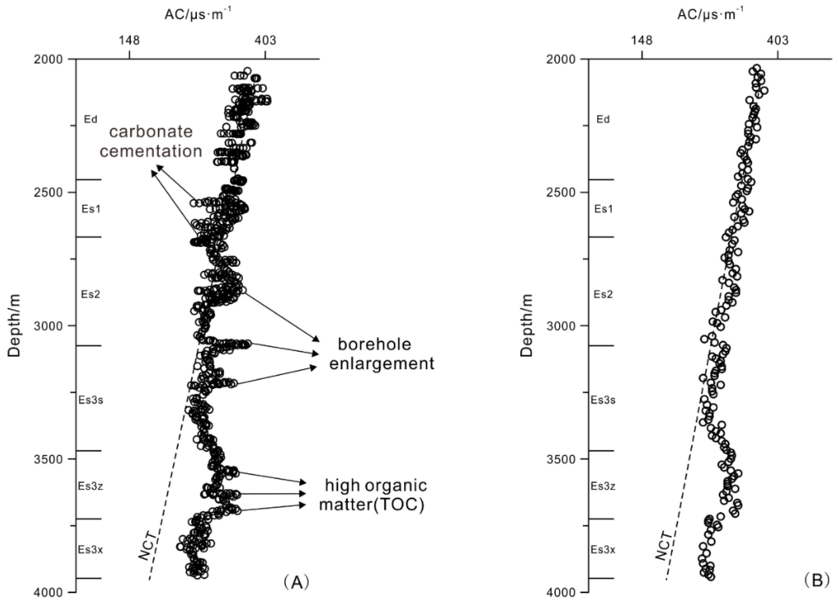
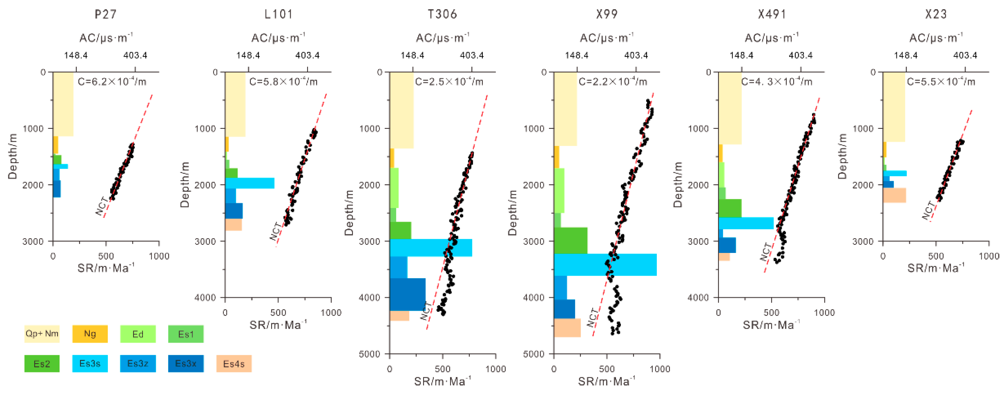
The sedimentary facies considerably vary in continental basins, and it is often difficult to maintain similar mudstone compaction trends in different layers because of factors such as lithology, mineral composition, faults, and unconformities. The compaction curves are too scattered to determine the normal compaction trend and the top of the disequilibrium compaction zone, to identify the overpressure mechanisms and estimate pressures. Studies on mudstone compaction, must eliminate these non-compaction factors as much as possible. Reliable mudstone compaction curves and loading curves are essential to the accuracy of overpressure origins identification and the estimated overpressure estimation.
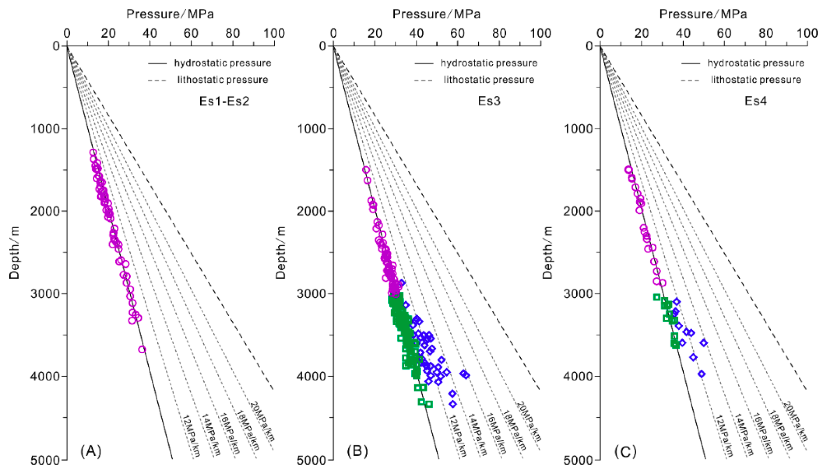
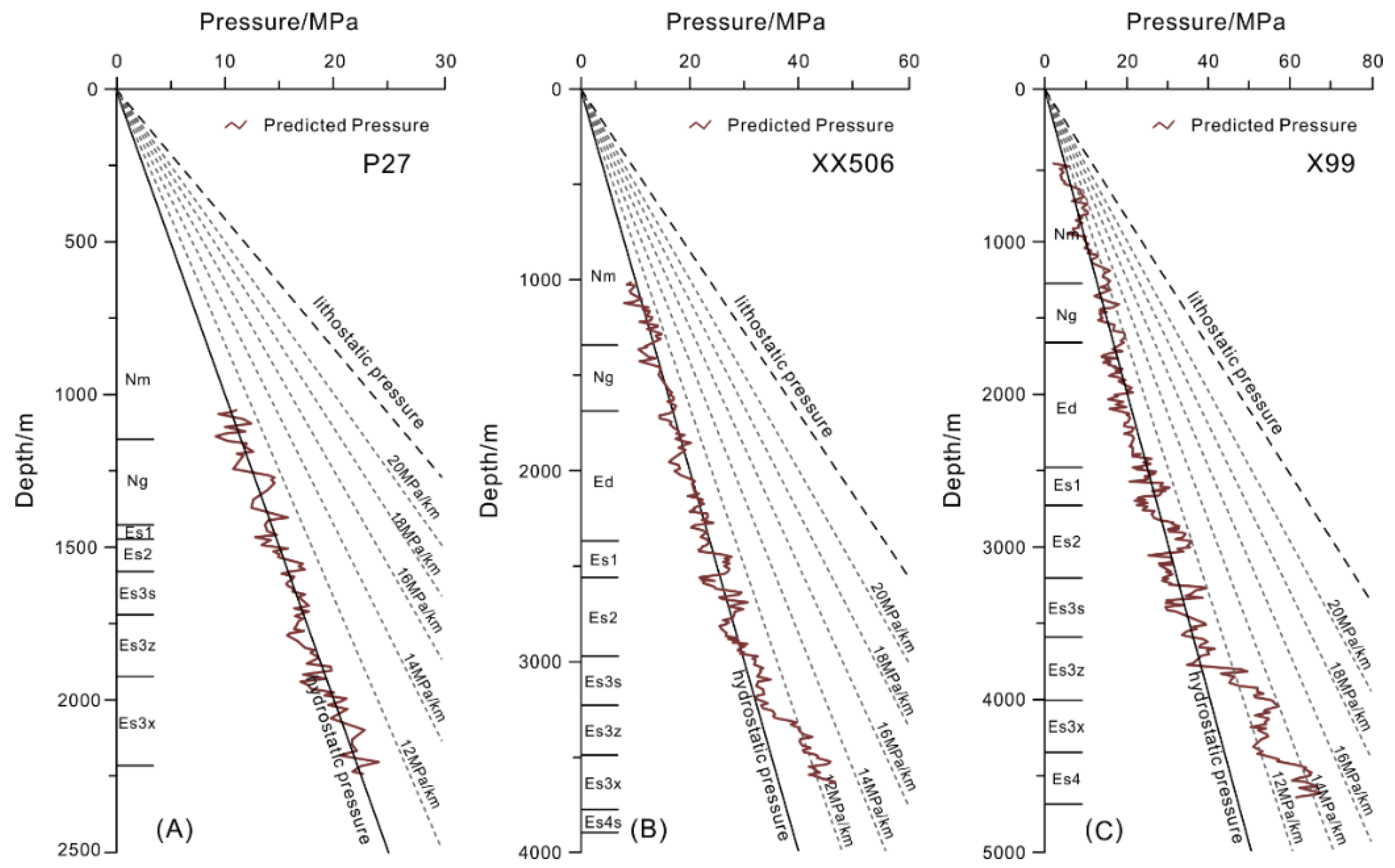
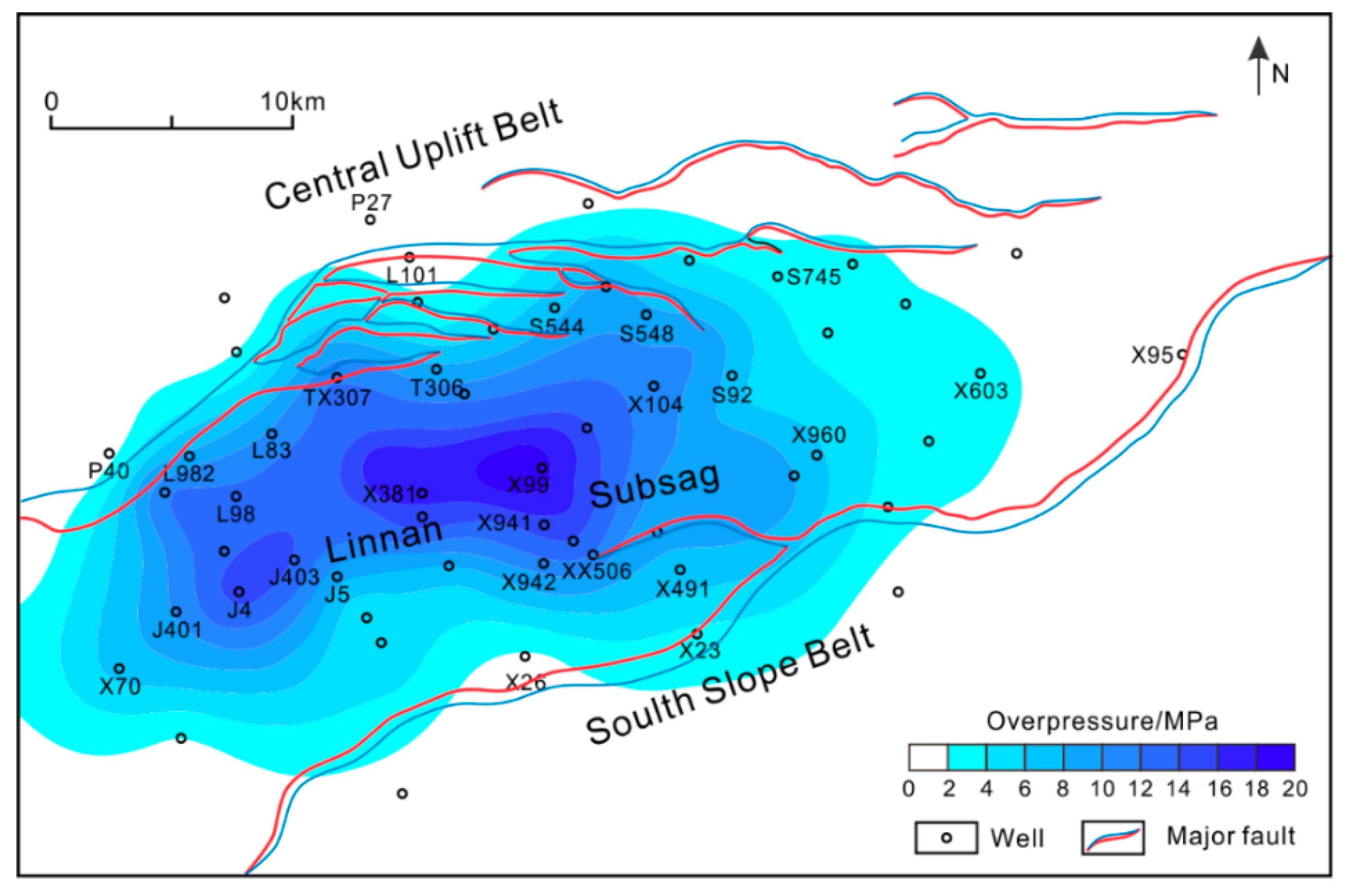
(2)
The pressures in Es1 and Es2 are normal, and clear overpressure zones occur primarily in the Es3 and Es4 intervals. The maximum pressure gradients in Es3 and Es4 are 16.2 and 14.3 MPa/km, respectively, and the maximum overpressures are approximately 24 and 14 MPa, respectively. The overpressures in the mudstones increase with depth and decrease gradually from the center of the sag to the margins, and they approach hydrostatic pressure in the uplift. The differences in the sealing conditions cause the coexistence of abnormal and normal pressures at similar depths, and the origin and preservation conditions of overpressure result in discrepancies between the reservoir and mudstone pressures.
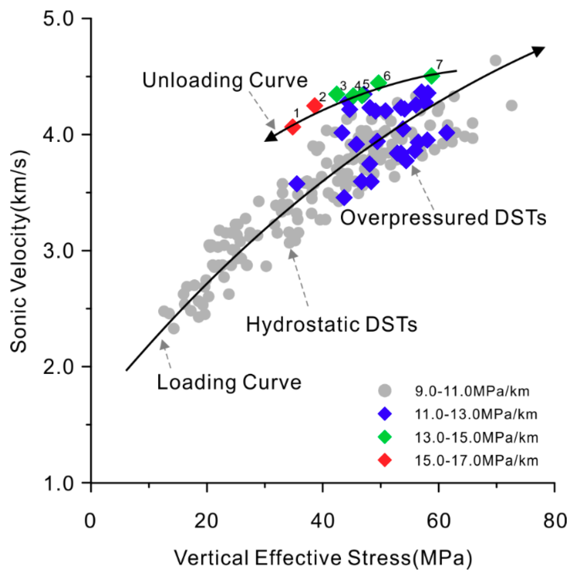
(3)
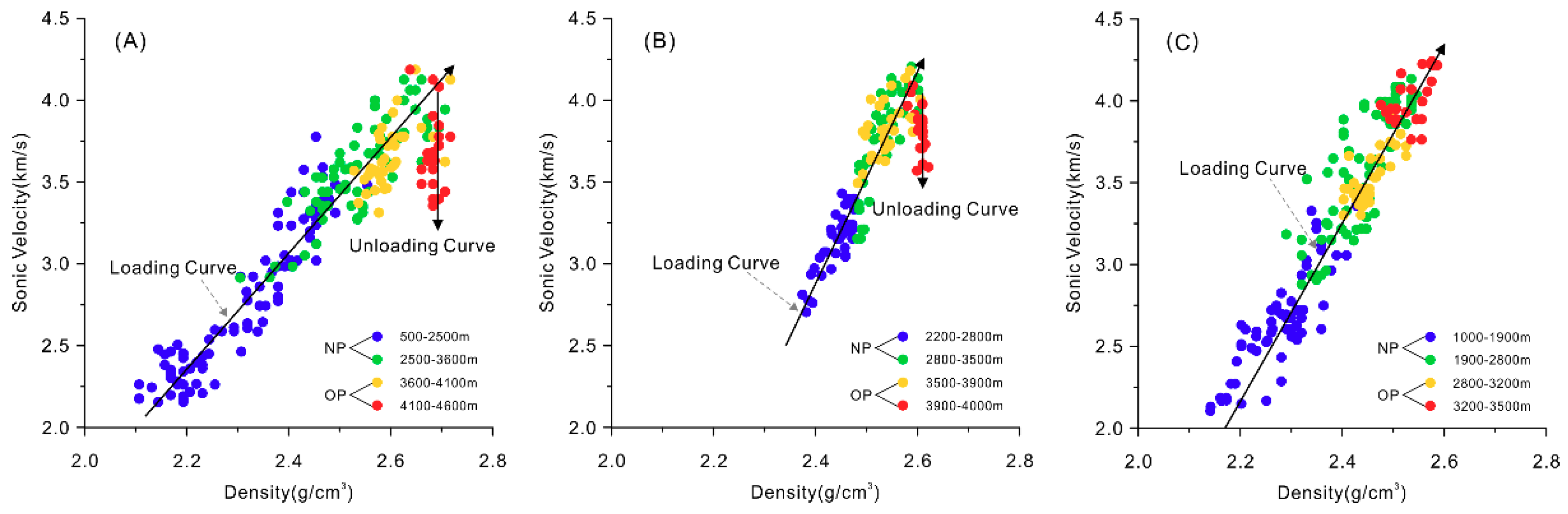
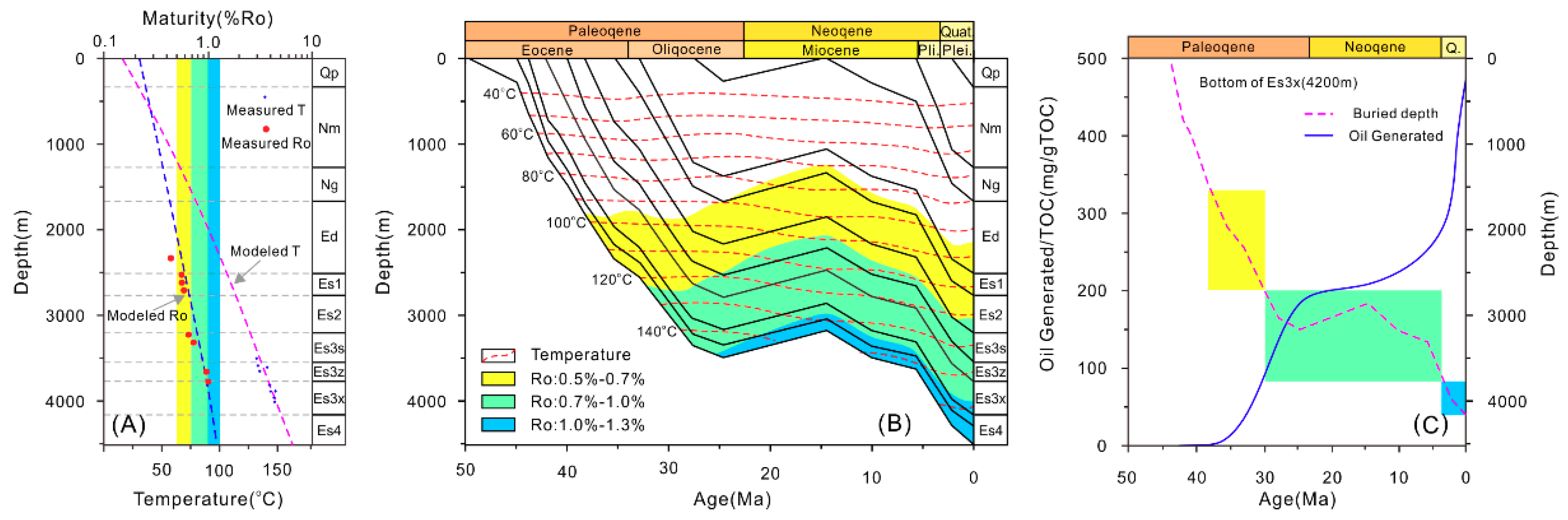
Mudstone disequilibrium compaction is the fundamental mechanism that generates overpressure, and the overpressured points follow the loading curve in the acoustic velocity/density–vertical effective stress and acoustic velocity–density crossplots. Due to the low TOC and low maturity, hydrocarbon generation is speculated to play a minor role in overpressure generation in the Linnan Sag. Vertical transfer may be the main unloading mechanism and is manifested as overpressure points that deviate from the loading curves. The transfer of overpressure through opening faults is likely the main cause of higher overpressure in local sandstones.

Author Contributions

Conceptualization, C.L.; Methodology, C.L., X.L., and L.Z.; Project administration, X.G. and H.L.; Validation, Y.L.; Visualization, B.W.; Writing—original draft, C.L. and L.Z.; Writing—review & editing, X.L.

Funding

This research was funded by the Strategic Priority Research Program of the Chinese Academy of Sciences (XDA14010202), and National Science and Technology Major Project (2017ZX05008-004).

Acknowledgments

The study would not have been possible without the support from Shengli Oil Company of China Petroleum & Chemical Corporation. We thank Shengli Oil Company for permission to publish this work. We are also thankful to assistant editor and two anonymous reviewers for their insightful comments and suggestions to improve the manuscript.

Conflicts of Interest

The authors declare no conflict of interest.

References

  1. Hao, F.; Zou, H.Y.; Gong, Z.S.; Yang, S.G.; Zeng, Z.P. Hierarchies of overpressure retardation of organic matter maturation: Case studies from petroleum basins in China. AAPG Bull. 2007, 91, 1467–1498. [Google Scholar] [CrossRef]
  2. Luo, X.R.; Vasseur, G. Natural hydraulic cracking: Numerical model and sensitivity study. Earth Planet. Sci. Lett. 2002, 201, 431–446. [Google Scholar] [CrossRef]
  3. Stricker, S.; Jones, S.J.; Sathar, S.; Bowen, L.; Oxtoby, N. Exceptional reservoir quality in HPHT reservoir settings: Examples from the Skagerrak Formation of the Heron Cluster, North Sea, UK. Mar. Pet. Geol. 2016, 77, 198–215. [Google Scholar] [CrossRef] [Green Version]
  4. Tingay, M.R.P.; Morley, C.K.; Laird, A.; Limpornpipat, O.; Krisadasima, K.; Pabchanda, S.; Macintyre, H.R. Evidence for overpressure generation by kerogen –to-gas maturation in the northern Malay Basin. AAPG Bull. 2013, 97, 639–672. [Google Scholar] [CrossRef]
  5. Muggeridge, A.; Abacioglu, Y.; England, W.; Smalley, C. The rate of pressure dissipation from abnormally pressured compartments. AAPG Bull. 2005, 89, 61–80. [Google Scholar] [CrossRef]
  6. Najibi, A.R.; Ghafoori, M.; Lashkaripou, G.R.; Asef, M.R. Reservoir geomechanical modeling: In-situ stress, pore pressure, and mud design. J. Pet. Sci. Eng. 2017, 151, 31–39. [Google Scholar] [CrossRef]
  7. Shi, Y.L.; Wang, C.Y. Pore pressure generation in sedimentary basins: Overloading versus aquathermal. J. Geophys. Res. Solid Earth Planets 1986, 91, 2153–2162. [Google Scholar] [CrossRef]
  8. Luo, X.R.; Vasseur, G. Contributions of compaction and aquathermal pressuring to geopressure and the influence of environmental conditions. AAPG Bull. 1992, 76, 1550–1559. [Google Scholar]
  9. Osborne, M.J.; Swarbrick, R.E. Mechanisms for generating overpressure in sedimentary basins: A reevaluation. AAPG Bull. 1997, 81, 1023–1041. [Google Scholar]
  10. Wangen, M. A quantitative comparison of some mechanisms generating overpressure in sedimentary basins. Tectonophysics 2001, 334, 211–234. [Google Scholar] [CrossRef]
  11. Tingay, M.R.P.; Hillis, R.R.; Swarbrick, R.E.; Morley, C.K.; Damit, A.R. Origin of overpressure and pore-pressure prediction in the Baram province, Brunei. AAPG Bull. 2009, 93, 51–74. [Google Scholar] [CrossRef]
  12. Luo, X.R.; Vasseur, G. Overpressure dissipation mechanisms in sedimentary sections consisting of alternating mud-sand layers. Mar. Pet. Geol. 2016, 78, 883–894. [Google Scholar] [CrossRef]
  13. Luo, X.R.; Yang, J.H.; Wang, Z.F. The overpressuring mechanisms in aquifers and pressure prediction in basins. Geol. Rev. 2000, 46, 22–31. [Google Scholar]
  14. Luo, X.R.; Vasseur, G. Geopressuring mechanism of organic matter cracking: Numerical modeling. Bull. Am. Assoc. Pet. Geol. 1996, 80, 856–874. [Google Scholar]
  15. Swarbrick, R.E.; Osborne, M.J.; Yardley, G.S. Comparison of overpressure magnitude resulting from the main generating mechanisms. In Pressure Regimes in Sedimentary Basins and Their Prediction; Huffman, A., Bowers, G., Eds.; AAPG Memoir 76: Tulsa, OK, USA, 2002; pp. 1–12. [Google Scholar]
  16. Law, B.E.; Spencer, C.W. Abnormal pressures in hydrocarbon environments. In Abnormal Pressures in Hydrocarbon Environments; Law, B.E., Ulmishek, G.F., Slavin, V.I., Eds.; AAPG Memoir 70: Tulsa, OK, USA, 1998; pp. 1–11. [Google Scholar]
  17. Ruth, P.V.; Hillis, R.; Tingate, P. The origin of overpressure in the Carnarvon Basin, western Australia: Implications for pore-pressure prediction. Pet. Geosci. 2004, 10, 247–257. [Google Scholar] [CrossRef]
  18. Swarbrick, R.E.; Osborne, M.J. Mechanisms that generate abnormal pressures: An overview. In Abnormal Pressures in Hydrocarbon Environments; Law, B.E., Ulmishek, G.F., Slavin, V.I., Eds.; AAPG Memoir 70: Tulsa, OK, USA, 1998; pp. 13–34. [Google Scholar]
  19. Magara, K. Compaction and Fluid Migration: Practical Petroleum Geology; Elsevier Science: Amsterdam, The Nederland, 1978; pp. 1–215. [Google Scholar]
  20. Bowers, G.L. Detecting High Overpressure. Lead. Edge 2002, 21, 174–177. [Google Scholar] [CrossRef]
  21. Zhang, J.C. Pore pressure prediction from well logs: Methods, modifications, and new approaches. Earth Sci. Rev. 2011, 108, 50–63. [Google Scholar] [CrossRef]
  22. Bowers, G.L. Pore pressure estimation from velocity data: Accounting for overpressure mechanisms besides undercompaction. SPE Drill. Complet. 1995, 10, 89–95. [Google Scholar]
  23. Hermanrud, C.; Wensaas, L.; Teige, G.M.G.; Nordgård, H.M.; Hansen, S.; Vik, E. Shale porosities from well logs on Haltenbanken (Offshore Mid-Norway) show no influence of overpressuring. In Abnormal Pressures in Hydrocarbon Environments; Law, B.E., Ulmishek, G.F., Slavin, V.I., Eds.; AAPG Memoir 70: Tulsa, OK, USA, 1998; pp. 65–85. [Google Scholar]
  24. Bowers, G.L.; Katsube, T.J. The role of shale pore structure on the sensitivity of wire-line logs to overpressure. In Pressure Regimes in Sedimentary Basins and Their Prediction; Huffman, A., Bowers, G., Eds.; AAPG Memoir 76: Tulsa, OK, USA, 2002; pp. 43–60. [Google Scholar]
  25. Zhang, J.C. Effective stress, porosity, velocity and abnormal pore pressure prediction accounting for compaction disequilibrium and unloading. Mar. Pet. Geol. 2013, 45, 2–11. [Google Scholar] [CrossRef]
  26. Lahann, R.W. Gulf of Mexico overpressure and clay diagenesis without unloading: An anomaly? AAPG Bull. 2017, 101, 1859–1877. [Google Scholar] [CrossRef]
  27. Swarbrick, R.E. Review of pore-pressure prediction challenges in high-temperature areas. Lead. Edge. 2012, 31, 1288–1294. [Google Scholar] [CrossRef]
  28. Dasgupta, S.; Chatterjee, R.; Mohanty, S.P. Magnitude, mechanisms and prediction of abnormal pore pressure using well data in the Krishna Godavari Basin, East coast of India. AAPG Bull. 2016, 100, 1833–1855. [Google Scholar] [CrossRef]
  29. Fan, C.Y.; Wang, Z.L.; Wang, A.G.; Fu, S.T.; Wang, L.Q.; Zhang, Y.S.; Kong, X.X.; Zhang, X. Identification and calculation of transfer overpressure in the northern Qaidam Basin, northwest China. AAPG Bull. 2016, 100, 23–39. [Google Scholar] [CrossRef]
  30. Tingay, M.R.P.; Hillis, R.R.; Swarbrick, R.E.; Morley, C.K.; Damit, A.R. Vertically transferred overpressures in Brunei: Evidence for a new mechanism for the formation of high-magnitude overpressure. Geology 2007, 35, 1023–1026. [Google Scholar] [CrossRef]
  31. Swarbrick, R.E. Challenges of Porosity-Based Pore Pressure Prediction. In Proceedings of the 63rd EAGE Conference & Exhibition, Amsterdam, The Nederlands, 11–15 June 2001. [Google Scholar]
  32. Aplin, A.C.; Yang, Y.L.; Hansen, S. Assessment of β the compression coefficient of mudstones and its relationship with detailed lithology. Mar. Petr. Geol. 1995, 12, 955–963. [Google Scholar] [CrossRef]
  33. Zhang, F.Q.; Wang, Z.L.; Wu, Y.S.; Yang, J.H.; Luo, X.R. A method for eliminating geology factors of affecting compaction trendline. Acta Sedimentol. Sin. 2002, 20, 326–332. [Google Scholar]
  34. Mondol, N.H.; Bjørlykke, K.; Jahren, J.; Høeg, K. Experimental mechanical compaction of clay mineral aggregates—Changes in physical properties of mudstones during burial. Mar. Pet. Geol. 2007, 24, 289–311. [Google Scholar] [CrossRef]
  35. Li, C.; Zhang, L.K.; Luo, X.R.; Zhang, L.Q.; Hu, C.Z.; Qi, Y.K.; Lei, Y.H.; Cao, B.F.; Cheng, M.; Yu, Y.X. Calibration of the mudrock compaction curve by eliminating the effect of organic matter in organic-rich shales: Application to the southern Ordos Basin, China. Mar. Petr. Geol. 2017, 86, 620–635. [Google Scholar] [CrossRef]
  36. Chen, H.L.; Luo, X.R. Study of mudstone compaction curves and analysis of migration conditions of oil and gas. Oil Gas Geol. 1987, 8, 233–242. [Google Scholar]
  37. Luo, X.R.; Dong, W.L.; Yang, J.H.; Yang, W. Overpressuring mechanisms in the Yinggehai Basin, South China Sea. AAPG Bull. 2003, 87, 629–645. [Google Scholar] [CrossRef]
  38. Zhu, Z.Q.; Zeng, J.H.; Wang, J.J. Hydrocarbon migration characteristics of Linnan Sag in Huimin Depression. J. Southwest Pet. Univ. (Sci. Technol. Ed.) 2010, 32, 33–38. [Google Scholar]
  39. Wang, Y.S.; Qiu, Y.B. Overpressure structure dissimilarity and its controlling factors in the Jiyang Depression. Oil Gas Geol. 2017, 38, 430–437. [Google Scholar]
  40. Wang, B.; Zhang, L.K.; Li, C.; Chen, K.Y.; Song, G.Q.; Luo, H.M. Mechanism and distribution prediction of abnormal high pressure of the Paleocene Shahejie Formation in Linnan Sag, Huimin Depression. Oil Gas Geol. 2018, 39, 641–652. [Google Scholar]
  41. Liu, H.M. Hydrocarbon Migration and Accumulation Direction and Distribution of Linnan Sag in Jiyang Depression. Geoscience 2009, 23, 894–901. [Google Scholar]
  42. Liu, X.F. Distribution and origin of the abnormal pressure in a transtensional basin: A case study from Linan Subsag, Humin Sag. Geolo. Sci. Technol. Inf. 2011, 30, 1–4. [Google Scholar]
  43. Li, C.Q.; Liu, H.M. Abnormal formation pressure and its evolution features of the third member, Shahejie Formation, Linnan Sag. Earth Sci. J. China Univ. Geosci. 2013, 38, 105–111. [Google Scholar]
  44. Guo, X.W.; He, S.; Liu, K.Y.; Song, G.Q.; Wang, X.J.; Shi, W.Z. Oil generation as the dominant overpressure mechanism in the Cenozoic Dongying depression, Bohai Bay Basin, China. AAPG Bull. 2010, 94, 1859–1881. [Google Scholar] [CrossRef]
  45. Wang, B.J.; He, S.; Song, G.Q.; Wang, Y.S.; Wang, X.J.; Hao, X.F.; Luo, S.Y. Effective stress characteristics of different overpressured origins in Dongying Depression of the Bohai Bay Basin, China. Geol. Sci. Technol. Inf. 2012, 31, 72–79. [Google Scholar]
  46. He, S.; Song, G.Q.; Wang, Y.S.; Hao, X.F.; Wang, B.J.; Li, N.; Luo, S.Y. Distribution and Major Control Factors of the Present-Day Large-Scale Overpressured System in Dongying Depression. Earth Sci.-J. China Univ. Geosci. 2012, 37, 1029–1042. [Google Scholar]
  47. Chen, W.; Wu, Z.P.; Hou, F. Relationship between hydrocarbon accumulation and Linshang fault zone in Linnan area, Huimin depression. Pet. Geol. Recovery Effic. 2010, 17, 25–28. [Google Scholar]
  48. Wu, K.Y.; Zhao, Z.X.; Cui, S.L.; Li, J.Y. Controlling of Xiakou fault on hydrocarbon accumulation in the sourthern part of Huimin depression. J. Geomech. 2012, 18, 32–41. [Google Scholar]
  49. Feng, D.X.; Ye, F. Structure kinematics of a transtensional basin: An example from the Linnan Subsag, Bohai Bay Basin, eastern China. Geosci. Front. 2018, 9, 917–929. [Google Scholar] [CrossRef]
  50. Ni, J.L.; Guo, Y.; Wang, Z.M.; Liu, J.L.; Lin, Y.X.; Li, Y. Tectonics and Mechanisms of Uplift in the Central Uplift Belt of the Huimin Depression. J. Earth Sci. 2011, 22, 299–315. [Google Scholar] [CrossRef]
  51. Cao, Y.C.; Wang, S.J.; Wang, Y.Z.; Yang, T.; Zhang, S.M.; Zhang, H.N. Sedimentary characteristics and depositional model of slumping deep-water gravity flow deposits: A case study from the middle Member 3 of Paleogene Shahejie Formation in Linnan subsag, Bohai Bay Basin. J. Palaeogeogr. 2017, 19, 419–432. [Google Scholar]
  52. Guo, X.L.; Xiong, M.; Zhou, Q.; Tian, H.; Xiao, X.M. Petroleum generation and expulsion kinetics: A case study of the Shahejie formation source rocks from Linnan Sag of Huimin Depression. Acta Sedmentol. Sin. 2009, 27, 723–731. [Google Scholar]
  53. Li, Q.; Jiang, Z.X.; Liu, K.Y.; Zhang, C.M.; You, X.L. Factors controlling reservoir properties and hydrocarbon accumulation of lacustrine deep-water turbidites in the Huimin Depression, Bohai Bay Basin, East China. Mar. Pet. Geol. 2014, 57, 327–344. [Google Scholar] [CrossRef]
  54. Bredehoeft, J.D. The drill stem test—The petroleum industry’s deep-well pumping test. Ground Water 1965, 3, 31–36. [Google Scholar] [CrossRef]
  55. Carcione, J.M.; Helle, H.B.; Pham, N.H.; Toverud, T. Pore pressure estimation in reservoir rocks from seismic reflection data. Geophysics 2003, 68, 1569–1579. [Google Scholar] [CrossRef]
  56. Harrold, T.W.D. Porosity and Effective Stress Relationships in Mudrocks. Ph.D. dissertation, Durham University, Durham, England, 2001; pp. 31–35. [Google Scholar]
  57. Sayers, C.M.; Johnson, G.M.; Denyer, G. Predrill pore-pressure prediction using seismic data. Geophysics 2002, 67, 1286–1292. [Google Scholar] [CrossRef]
  58. Shaker, S.S. Causes of disparity between predicted and measured pore pressure. Lead. Edge 2002, 21, 756–760. [Google Scholar] [CrossRef]
  59. Sargent, C.; Goulty, N.R.; Cicchino, A.M.P.; Ramdhan, A.M. Budge–Fudge method of pore-pressure estimation from wireline logs with application to Cretaceous mudstones at Haltenbanken. Pet. Geosci. 2015, 21, 2014–2088. [Google Scholar] [CrossRef]
  60. Goulty, N.R.; Sargent, C.; Andras, P.; Aplin, A.C. Compaction of diagenetically altered mudstones—Part 1: Mechanical and chemical contributions. Mar. Pet. Geol. 2016, 77, 703–713. [Google Scholar] [CrossRef]
  61. Yang, Y.L.; Aplin, A.C. Definition and practical application of mudstone porosity-effective stress relationships. Pet. Geosci. 2004, 10, 153–162. [Google Scholar] [CrossRef]
  62. Hoesni, M.J. Origins of Overpressure in the Malay Basin and Its Influence on Petroleum Systems. Ph.D. dissertation, Durham University, Durham, UK, 2004; pp. 19–34. [Google Scholar]
  63. Marcussen, Ø.; Thyberg, B.I.; Peltonen, C.; Jahren, J.; Bjorlykke, K.; Faleide, J.I. Physical properties of Cenozoic mudstones from the northern North Sea: Impact of clay mineralogy on compaction trends. Bull. Am. Assoc. Pet. Geol. 2009, 93, 127–150. [Google Scholar] [CrossRef] [Green Version]
  64. Kalani, M.; Jahren, J.; Mondol, N.H.; Faleide, J.I. Compaction processes and rock properties in uplifted clay dominated units–the Egersund Basin, Norwegian North Sea. Mar. Pet. Geol. 2015, 68, 596–613. [Google Scholar] [CrossRef]
  65. Ni, J.L.; Zhang, H.; Tang, X.L.; Han, S. Diagenetic and paleogeothermal evolution of the clay minerals in the Center Uplift Belt and its adjacent region of Huimin Sag, Jiyang Depression. Nat. Gas Geosci. 2016, 27, 1778–1788. [Google Scholar]
  66. Audet, D.M.; McConnell, J.D.C. Forward modeling of porosity and pore pressure evolution in sedimentary basins. Basin Res. 1992, 4, 147–162. [Google Scholar] [CrossRef]
  67. Luo, X.R.; Vasseur, G. Modeling of pore pressure evolution associated with sedimentation and uplift in sedimentary basins. Basin Res. 1995, 7, 35–52. [Google Scholar] [CrossRef]
  68. Liu, Z.Y. Dynamics System of Petroleum Accumulation in the Linnan Depression. In Ph.D. dissertation; Guangzhou Institute of Geochemistry, Chinese Academy of Sciences: Guangzhou, China, 2003; pp. 1–130. [Google Scholar]
  69. Yardley, G.S.; Swarbrick, R.E. Lateral transfer: A source of additional overpressure? Mar. Pet. Geol. 2000, 17, 523–537. [Google Scholar] [CrossRef]
  70. Grauls, D.J.; Baleix, J.M. Role of overpressures and in situ, stresses in fault-controlled hydrocarbon migration: A case study. Mar. Pet. Geol. 1994, 11, 734–742. [Google Scholar] [CrossRef]
  71. Luo, X.R. Allogenic overpressuring associated with faulting and geological consequences. Acta Geol. Sin. 2004, 78, 641–648. [Google Scholar]
  72. Si, X.Q. The Research of Conditions for Hydrocarbon Accumulation of Kongdian Formation in Huimin Depression. Ph.D. dissertation, Ocean University of China, Qingdao, China, 2008; pp. 124–129. [Google Scholar]
  73. Meng, Y.; Han, Z.Z. Fault sealing and difference between the east section and the west section of Xiakou fault. China Sci. Paper 2015, 10, 1066–1070. [Google Scholar]
  74. O’Connor, S.A.; Swarbrick, R.E.; Jones, D. Where has all the pressure gone? Evidence from pressure reversals and hydrodynamic flow. First Break 2008, 26, 55–61. [Google Scholar] [CrossRef]
  75. Chang, X.C. Formation Mechnism and Occurrences of Lithilogical Petroleum Reservoirs of Es3 in Linnan Subsag. Ph.D. dissertation, Shandong University of Science and Technology, Qingdao, China, 2007; pp. 38–91. [Google Scholar]
  76. Haney, M.M.; Snieder, R.; Sheiman, J.; Steven, L. A moving fluid pulse in a fault zone. Nature 2005, 437, 46. [Google Scholar] [CrossRef]
  77. Tian, Z.H. The Investigation of the Depositional System in Linnan Low-Laying Upper Es4 and the Evaluation of Exploration Potential. Ph.D. dissertation, Ocean University of China, Qingdao, China, 2007; pp. 1–116. [Google Scholar]
Figure 1. Structural location and well distribution of the Linnan Sag. (A) Location of the Huimin Depression. (B) Structural units of the Huimin Depression. (C) Tectonic setting of the Linnan Sag with the locations of wells. (D) Schematic north–south geologic cross section of the Linnan Sag.
Energies 12 03183 g001
Figure 2. General Cenozoic stratigraphy of the Linnan Sag. The age, thickness, and lithology of each formation and the potential source, reservoir, and caprocks are shown.
Energies 12 03183 g002
Figure 3. Comprehensive mudstone compaction curves of well X99, including (A) acoustic, (B) density, (C) neutron logs, (D) mud weights (MW), and DST data. The well location is shown in Figure 1C.
Energies 12 03183 g003
Figure 4. Comparison of the measured pressures and mud weight equivalent pressures. Pmea is the measured pressure, and Pmud is the pressure calculated from the mud weight.
Energies 12 03183 g004
Figure 5. Plots of pressure versus depth for (A) Es1–Es2, (B) Es3, (C) and Es4 in the Linnan Sag. Overpressure developed in the Es3 and Es4. The measured pressure data were obtained from DSTs in wells. The sand bodies with normal pressure are either in hydrostatic environment (purple circle), or are laterally continuous or connected by faults (green square), while the sandstone that developed overpressure is mainly isolated sand bodies (blue diamond).
Energies 12 03183 g005
Figure 6. Estimated pressures in mudstone in the Linnan Sag for well (A) P27, (B) XX506, and (C) X99. The locations of the wells are shown in Figure 1C.
Energies 12 03183 g006
Figure 7. Distribution of the estimated overpressures in mudstone in Es3 in the Linnan Sag. The overpressure is highest in the center and gradually decreases toward the margins of the sag.
Energies 12 03183 g007
Figure 8. Relationship between the estimated pressure in mudstone and the measured pressure in the reservoir. The columns of lithology are also showed on the right of the well. (A) The pressure in the sandstone is equal to that in the mudstone in well X99; (B) the pressure in the sandstone is higher than that in the mudstone in well X381; (C) the pressure in the sandstone is lower than that in the mudstone in well X38. The well locations are shown in Figure 1C.
Energies 12 03183 g008
Figure 9. Acoustic velocity–vertical effective stress crossplots for the Linnan Sag. The points are on or near the loading curve, indicating normal compaction, or disequilibrium compaction (blue points), whereas the overpressured data lie on an unloading curve, suggesting that the overpressure is generated by fluid expansion or transfer processes (green and red points).
Energies 12 03183 g009
Figure 10. Acoustic velocity–density crossplots for well (A) X99, (B) X381, and (C) X960 in the Linnan Sag. Points remain on or near the loading curve, indicating disequilibrium compaction, while the overpressured data lie on an unloading curve, suggesting that the overpressure is generated by fluid expansion or transfer processes. NP = normal pressure, OP = overpressure. The well locations are shown in Figure 1C.
Energies 12 03183 g010
Figure 11. Mudstone compaction curves for well X942 in the Linnan Sag. (A) The compaction curve before elimination has a scattered data distribution. The lower acoustic values are due to the carbonate cementation in Es1, the abnormally high acoustic values in Es2 and Es3s are due to borehole enlargement, and the abnormally high acoustic difference between Es3z and Es3x is due to the high organic matter content. (B) The compaction curve after elimination of multiple factors is more regular. The well location is shown in Figure 1C.
Energies 12 03183 g011
Figure 12. The relationship between the sedimentary rate of formations (colorful rectangles) and compaction curves (black dots) of six wells in the Linnan Sag. The compaction coefficient equals the slope of the normal compaction trend. NCT = normal compaction trend; SR = sedimentation rates; C = compaction coefficient. The locations of the section and the wells are shown in Figure 1C.
Energies 12 03183 g012
Figure 13. (A) Measured vitrinite reflectance (Ro, %) versus depth, which shows an exponential increase in Ro with depth. (B) Temperature versus depth in the Linnan Sag.
Energies 12 03183 g013
Figure 14. Modeling results for well X99 in the Linnan Sag. (A) Modeled maturity and temperature of well X99 in the Linnan Sag. The modeled vitrinite reflectance and temperature versus depth curve fit well with the measured data. (B) Maturation and burial history of X99 in the Linnan Sag. (C) History of oil generation from the third member of the Shahejie Formation (Es3). Ro = vitrinite reflectance; T = temperature. The location of the well is shown in Figure 1C.
Energies 12 03183 g014
Figure 15. (A) Distribution of the reservoir pressure superposed with sedimentary facies in the Linnan Sag (the sedimentary facies are modified from [75]). SR = measured reservoir pressure, MF = major fault, CS = cross section, DC = distributary channel, SP = swamp, DP = delta plain, DF = delta front, SSL = shore shallow lacustrine, SD = semi-deep and deep lacustrine, TS = turbidite sandstone. (B) The distribution of reservoir pressure and mudstone pressure in a cross section in the Linnan Sag shows the complex characteristics of the pressure systems (the sandstone and fault interpretations are modified from [75]). Purple stars are normal pressured sandstones in hydrostatic environment, or are laterally continuous or connected by faults, red stars refer to isolated overpressured sand bodies.
Energies 12 03183 g015
Table 1. Corresponding information about the DST overpressure data for the unloading mechanisms in Figure 9.
LabelWellFormationDepth/mPP/MPaOP/MPaPG/(MPa/km)
1X941Es3x3978.9862.9123.1215.8
2X381Es3x4007.863.9624.6816.0
3S92Es4s3714.551.6515.2413.9
4S548Es3z3814.4652.2114.3713.6
5X99Es3s3896.0050.6114.0213.5
6TX307Es3z4216.0054.4613.1413.0
7L83Es3x4342.0857.6514.9713.3
Note: The number of the label corresponds to the marked order in Figure 9. PP = pore pressure; OP = overpressure; PG = pressure gradient.

