Article

Design and Implementation of a Low Power Outer-Rotor Line-Start Permanent-Magnet Synchronous Motor for Ultra-Light Electric Vehicles

Department of Electric and Electronics Engineering, Pamukkale University, Kinikli, 20160 Denizli, Turkey
*
Author to whom correspondence should be addressed.
Energies 2019, 12(16), 3174; https://doi.org/10.3390/en12163174
Submission received: 5 July 2019 / Revised: 10 August 2019 / Accepted: 13 August 2019 / Published: 19 August 2019
(This article belongs to the Section E: Electric Vehicles)

Abstract

:
Recently, while electric vehicles (EV) have substituted the fossil fuel vehicles, the design of the electrical motors with more efficient and less mechanical converters has become mandatory due to the weighting gears, mechanical differentials, and other cost-increasing parts. To overcome these problems, double electrical motors with low speed and high torque have been designed and used in the rear wheels of the EVs without any gearbox and mechanical differential. In this study, a novel outer rotor line-start hybrid synchronous motor is proposed as another solution. For this aim, four different hybrid rotor types, including magnets and rotor bars, have been designed and analyzed. Calculation and estimation of all parameters to design a motor are introduced. All of the analyses were carried out by Finite Elements Method (FEM). One of the analyzed motors, which is called Type-D was selected and implemented because of the best startup performance and better steady-state behavior under the rated load and overload. While holding this motor at synchronous speed under nominal load, in case of overloading, it remained in asynchronous mode, thus maintaining the sustainability of the system. Obtained results prove that the newly proposed outer rotor LSSM has the advantages of both synchronous motor and asynchronous motor. All of the experimental results validate the simulations well. The effects of the magnet alignments and dimensions on the performance of the motors are presented.

1. Introduction

In recent years, with the depletion of fossil fuel reserves, the search for alternative energy sources has continued rapidly. Various power plants are being established to meet the increasing energy demand. However, as a transport sector, which plays a major role in the consumption of fossil fuels, developments on the electric vehicles’ (EVs) technology will minimize the need for fossil fuels or eliminate dependence on fossil fuels completely. In addition, zero-emission electric vehicles (ZEVs) take over the role in reducing carbon emissions due to fossil fuel consumption. Although the cheapness of internal combustion engines encourages consumers, there will be an excessive increase in costs due to the decline in the supply of fossil fuels in the future. Nowadays, many vehicle manufacturers have turned to hybrid and fully EVs for the future [1].
Modern EVs consist of three main parts: the battery used as an energy source, the electric motor converting the stored electrical energy into the motion and other part is the powertrain. Depending on the six types of EV configurations in the literature, electric motors used in EVs can be classified as inner rotor and outer rotor. In the configurations where the preferred motors with inner rotor are used, mechanical differentials and gears must be commonly used. But, if the selected motors with outer rotor are placed in the wheels, it does not require additional mechanical transmission parts. Since the electric motors with outer rotor transfer the needed power directly to the wheels, an efficiency increase can be achieved compared to that of inner rotor for the same power. On the other hand, the lack of transmission components reduces the rotational inertia of the vehicle. Moreover, the direct placement of the electric motors on the wheels reduces the center of gravity of the motor and reduces the number of moving parts. It is another advantage to place the electric motor on each wheel if desired [2].
The electric motors directly determine the torque-speed and power-speed characteristics of EVs. Furthermore, the electric motors are suitable for the high torque and acceleration at any low speed. Typical electric motor characteristics are examined in constant torque and constant power region. The selection of the most suitable electric motors for the EVs were declared in the literature [3,4,5]. DC motor, induction motor, synchronous motor, reluctance motor and hybrid motors types with inner rotor have been investigated for EVs. In the early years, DC motors were used in EVs because of controlling easy. However, the interest in DC motors has been decreased because of the maintenance of the brushes. In addition, developments of technology on the AC drives, induction motors (IMs) with simple structure and having relatively higher efficiency have been preferred. Furthermore, lots of studies have been conducted with permanent magnet and reluctance motor by the researchers and manufacturers. In a comparative study using the finite element method (FEM) on a few electrical motors, such as the interior permanent magnet synchronous motor (IPMSMs), the synchronous reluctance motor (SynRMs) and IMs, which are designed for EVs, it is concluded that the SMs are more efficient than others, especially at low speeds. However, the core losses of the IPMSMs at high speeds are higher than the IMs. In terms of the vibration, the switching reluctance motors (SRMs) have disadvantages with respect to the others [6]. In another study, an IPMSM, a surface-mount permanent magnet SM (SMPMSM) and an IM were compared with each other. The results of this research showed that the PMs are more efficient than the IMs because of no cage losses. On the other hand, the SMPMSMs have not always more torque density [7].
In recent years, works on the motors with outer rotor have been intensified to get rid of efficiency reducing components such as clutch, gearbox and mechanical differentials in the EVs. At the same times, the brushless DC motor (BLDC) has been most commonly used in the outer rotor applications. In a study using finite element method (FEM) to design a direct-drive BLDC motor for the EVs, the torque fluctuations were reduced from 17.58% to 8.4% [8]. The BLDC motors, dual-stator and dual-field-excitation permanent magnet motors (DDPM), permanent magnet Vernier motors (PMVM), permanent magnet (PM) motors, permanent magnet flux switching (PMFS) motors and axial-flux (AF) motors with an outer rotor structure have been designed to be used in electric vehicles. The AF motor with radial active part designed for the range-extended electric vehicle has sufficient torque density [9]. In the FS Motor topology with a different number of slots and poles, the magnet ratio of the motors was reduced to 54%. In addition to that, the cogging torque was decreased by 20% while the average torque was decreased by only 1.80% [10]. The IPM type, SPM type, PMFS type and PMVM type with six-phase were compared in a study [11]. The results of these studies show that PMVM is suitable for the EVs because of its high torque density and efficiency. Another way to get higher torque, better efficiency and power factor is to design a motor with outer rotor. However, the limited stator area causes overheating, flux saturation and demagnetization. Therefore, thermal analysis is required to determine the demagnetization at different temperatures as it was emphasized in Shu et al. [12]. Especially, the maximum torque improved, sufficient mechanical power and more efficiency can be obtained by proper alignment of the magnets for an outer rotor PM Synchronous Motor (OR-PMSM) while keeping the minimum value of cogging torque and low torque ripples [13].
Neither the IMs nor the SMs can meet the needs of the EVs up to now. As a different solution to provide these needs, a new line-start synchronous motor (LSSM) was designed to combine the advantages of IM and PMSM. For this purpose, many studies have been carried out in the literature on inner rotor LSSM. It was reported that the power factor and efficiency of LSSM are higher than the IM’s [14]. Also, the opportunities and design challenges of the motor have been covered. Despite higher cost and synchronization problems, LSSM has a high efficiency, high power factor and high-power density when compared to other motors [15]. Better performance at the startup and rapid synchronization have been achieved with the low magnetizing inductance [16]. The impact of the structure of the squirrel cage on the motor synchronization showed that the asymmetrical cage is useful to improve the startup performance [17]. Research has been conducted on motor efficiency and production cost by using different magnet materials [18]. Another solution for initial synchronization problem is to take deep bar replacement into account [19]. In a recent study, the effect of the skew angle on synchronization performance and torque ripples was also presented [20]. In the literature, to handle with the LSSM problems, several design studies have been carried out on inner rotor LSSM, and different methods for the magnet alignments to improve the design have been examined. In these studies, the simplest method is to add magnets to the inner rotors of the conventional induction motors. The other method is to implant a squirrel cage on the rotor of the SM [21]. Unlike the modification of existing motor types, a new design can be made. In general, to design a new motor, it is necessary to determine the geometry, calculate the stator parameters, and define the rotor type and their design parameters. However, the motor designed with initial design parameters may have a bad performance. Therefore, optimization of the parameters is required for the desired performance. There are several studies done for this objective in the literature related to the line start PMSM with inner rotor. In ref [22], torque density was increased by performing an optimization technique involved response surface methodology on the magnets size. Another study employed the genetic algorithm to improve the efficiency, power factor and starting performance [23]. Preferring a neural network based imperialist competitive algorithm is one of the other options to achieve optimum values of the rotor-slot parameters, such a study was presented in ref [24]. Design procedure and optimal guidelines for overall enhancement of steady-state and transient performances of line start permanent magnet motors with inner rotor were presented successfully in ref [25]. Proposed rotor type in that study includes embedded four-magnet and conventional rotor bar cage. The study was introduced with wholly parametrical analysis. On the other hand, stochastic optimization considering both steady state and dynamic capability of the designed motor was used to improve the maximum synchronous torque capacity [26]. One of the recent studies published on this issue declared that Taguchi-based regression rate method improved the steady-state and the transient synchronization performance [27].
Another option for improving the design is to figure out effects of the design parameters on the motor characteristics by the parametrical analysis. The first study on the line start PMSM with an outer hybrid rotor was presented in ref [28]. Where, this type motor called as outer rotor LSSM (OR-LSSM) by the authors, and introduced the synchronization performance of the OR-LSSM with three different hybrid rotor types under the unloaded condition. The results of the study showed that most of the line start inner rotor structures can be applied on the outer-rotor LSSM on condition optimizing the magnet size and the rotor bar with different alignments yielding better performance.
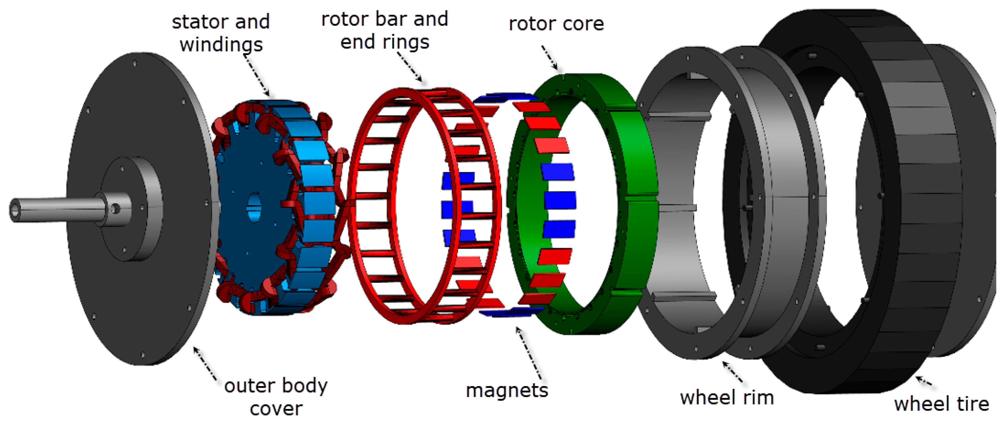
Importance of the outer hybrid rotor is that while the outer rotor maintains desired torque at synchronous speed, embedded rotor bars provides a soft starting to the motor and holding the motor stable in variable load-up system. In this study, a novel outer hybrid rotor configuration for the permanent magnet synchronous motors was presented. Considered comparison in introduction section of this study explains the differences between the others. All of the existing studies are on the inner rotor and their different configurations. Nevertheless, using in electrical vehicle, axial length of the tires and wheel rims are short and radial diameter is large. Therefore, outer rotor structure must be taken into account to provide necessary torque for the EV according to the tire dimensions. For this purpose, in this study four different outer hybrid rotor types were design and analyzed by FEM. The first three configuration introduced in this study (magnet alignments and bar replacements in Type-A, B and C) have been already processed for the inner hybrid rotors in the literature. In addition to these configurations a new hybrid outer rotor type (Type-D) was proposed and analyzed together with the others. One of these configurations, Type-D was selected to implement for the experiments because of its better performance. All of the experimental results validate the simulations for the proposed configuration in every aspect.
The paper is structured as follows. Firstly, Section 2 describes the design of inner stator and outer hybrid rotor, alignment of the magnets and replacement of the rotor bars. Section 3 presents the performance analysis of the designed motor types by FEM. Prototype implementation and experimental studies are given in Section 4. Finally, the conclusions are summarized in Section 5.

2. OR-LSSM Design

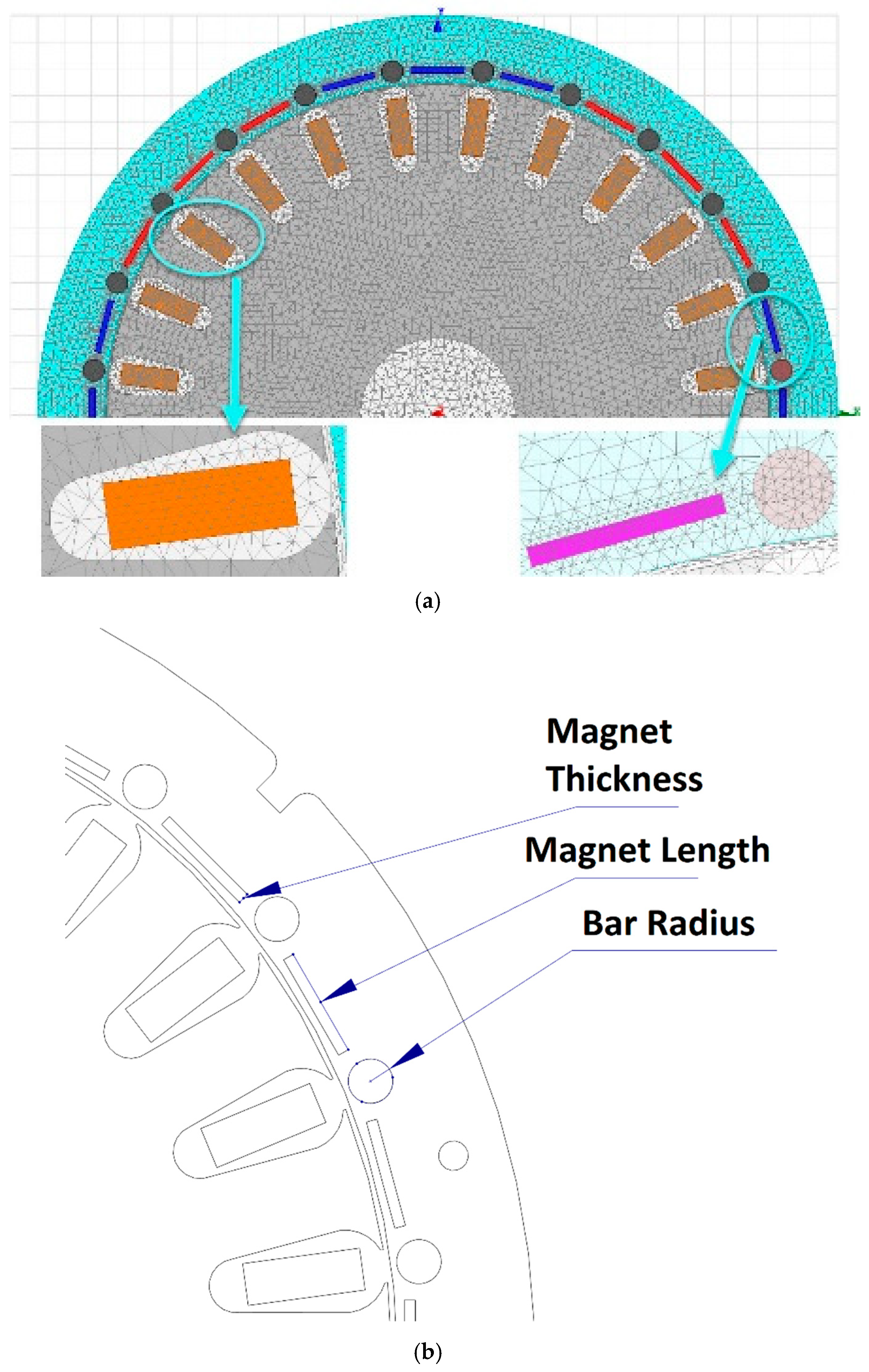
In the research, IM and PM motors have been used as the basis for hybrid motor design. Many analytical calculations related to IM design are available in the literature, and their structures are almost identical to the LSSMs. However, in this study, since the motor was designed to be completely non-standard main dimensions for the electric vehicle, stator, a rotor bar with several magnet configurations and their parameters (dimension, alignment types, the skew angle of the rotor-bar together with rotor laminations) were considered respectively.
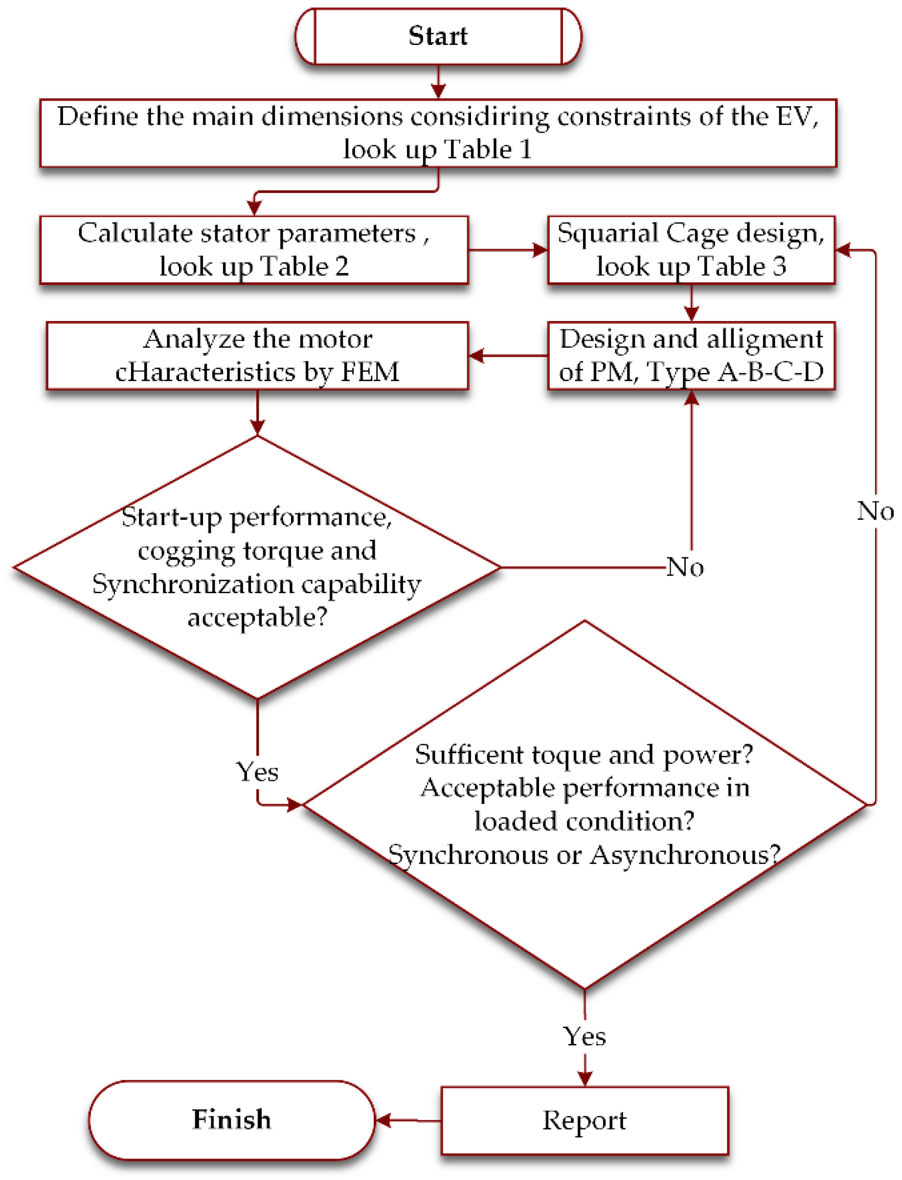
In general, to design and implement a motor, sufficient volume is firstly calculated for the desired power by taking the limitations into account. Then, the motor length is determined in accordance with the wheel diameter of an electric vehicle to be used. After calculating the length and diameter of the motor, the air gap is determined according to these dimensions to reduce unloaded speed oscillations and torque ripples. The conductors’ material, slot types and numbers in the stator and rotor as considering their configurations are identified depending on the pole-pair and motor power. In addition to that, cross-sectional area and number of turns of the conductors are estimated by some equations considering fill factor in the slots and saturation in the core due to stator winding and rotor bar current. Finally, the magnets are configured to insert into the outer rotor as to provide synchronization and minimize the losses in the steady-state operation. The design procedure is shown in Figure 1 as a flowchart.
After determination of the initial motor dimensions, optimization and parametric analysis by FEM is used to define the best parameters to achieve better efficiency, sufficient torque and good synchronization performance at low and high speed. If the motor does not produce sufficient torque, it is necessary to change the motor dimensions. In addition, it is essential to determine the proper magnet parameters to provide optimum synchronization.
One of the goals of these configurations, if any abandoning of synchronization occurs, asynchronous mode holds the motor at sub-synchronous speed without collapse for high load angle of PMSM in case of overload operation. The other goal is that, under conditions of nominal load transition, magnets in the rotor recovers the speed up to the synchronous.

2.1. Main Dimensions of the Machine

In general, the initial value of B av is selected in the interval of 0.35–0.6 Tesla [29]. Selecting a higher value of B av gives some benefits such as reducing the size of the motor, decreasing the cost and increasing overload capacity. The flux in the air gap per pole, ϕ , is given depending on the motor parameters and B av , as given in Table 1.
Where, B av is the average flux density in the air gap, D is the motor diameter, L is the motor axial length, n s is synchronous speed (rps), I ph is phase current, K w is winding factor and p is the number of poles.
The highest current capacity, as reducing the motor mass, results in more copper losses and increase the temperature. The proper value of current carrying capacity per square meter of conductor,   a c , can be selected in the interval of 1000–4500. In addition, the number of turns per phase,   T ph , is defined by Equation (3) in Table 1.
The relationship between D and L has great importance in terms of the characteristic behavior of the motor. The considered EV determines the most accurate detections for these parameters.

2.2. Inner Stator Design

The stator of the motors with both inner and outer rotor consists of a core and slots. Types of the slots, such as open slot and semi-closed slot, have an impact on the power factor and manufacturing. Assembly of semi-closed slots has some difficulties compared to the open slots. However, the motor characteristic behavior is better than the other one.
In Table 2, M is the number of phases, E s is the supply voltage per phase, g s is number of slots per pole per phase and δ s is current density of a conductor (about 3–5 A/mm2).

2.3. Outer Rotor Design

Considering the placements of the magnets in the rotor laminations for the studied models, the core slots are determined according to the slot pitch and number of slots per phase, by Equations (12) and (13) respectively, as given Table 3. In this table, the S r parameter is the number of the slots on the rotor.
It is assumed that the rotor magneto-motor force (MMF) on the flux route is accepted about 0.85 times to that of the stator. In addition, rotor current per conductor bar is calculated by Equation (15). Related to the current density in the rotor bar,   δ b , which is about 4–7 A/mm2, cross-sectional area of the rotor bar is obtained by Equation (16). End ring current per pole is calculated by Equation (17). After that, the cross-sectional area of the rotor end ring is obtained by Equation (18) corresponding to the current density in the rotor end ring, δ e , which is about 5–8 A/mm2. For detailed information about the equations in Table 1, Table 2 and Table 3 was referred to ref [30], the closely related references therein.

2.4. Orientation of the Magnets

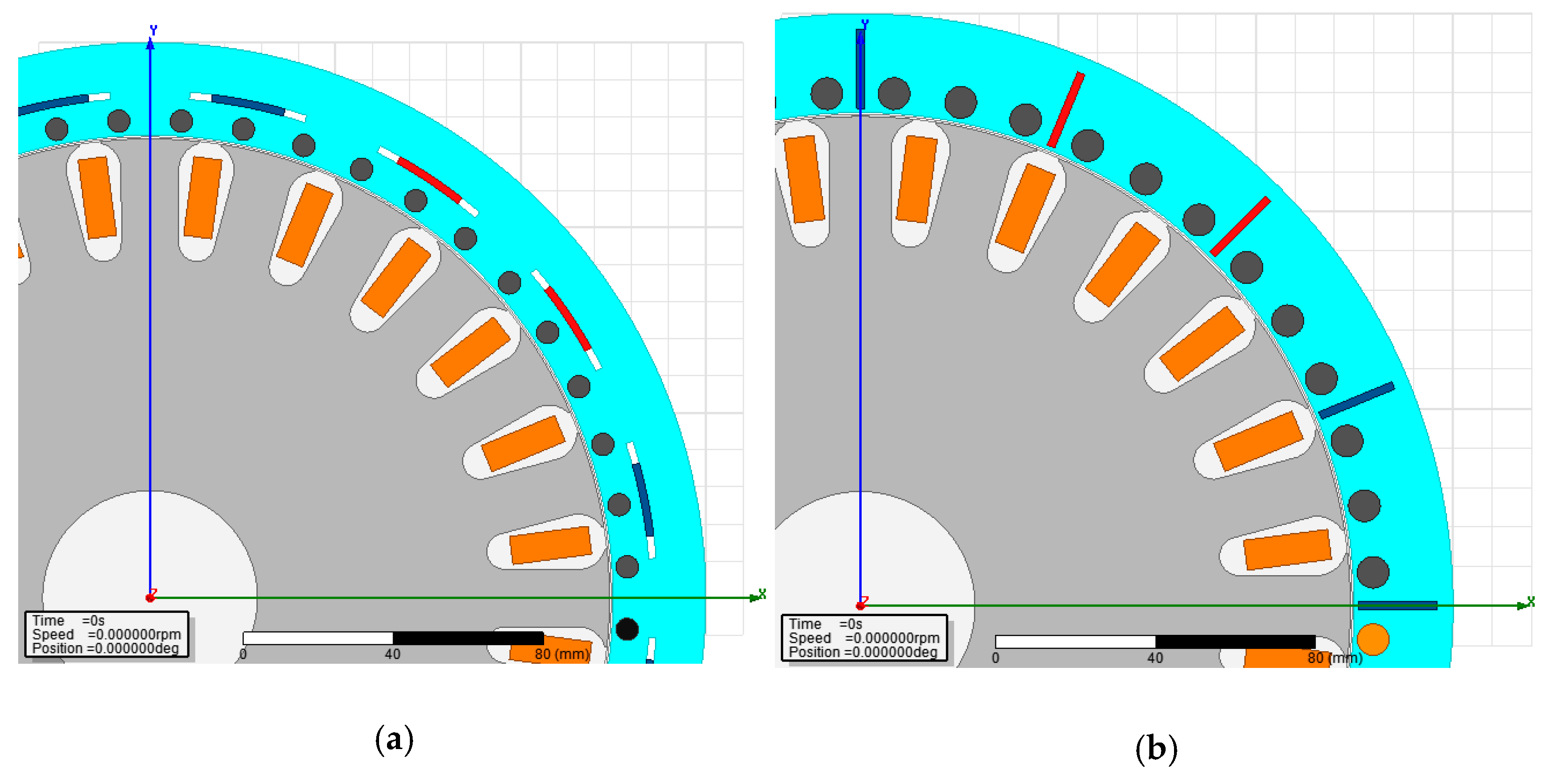
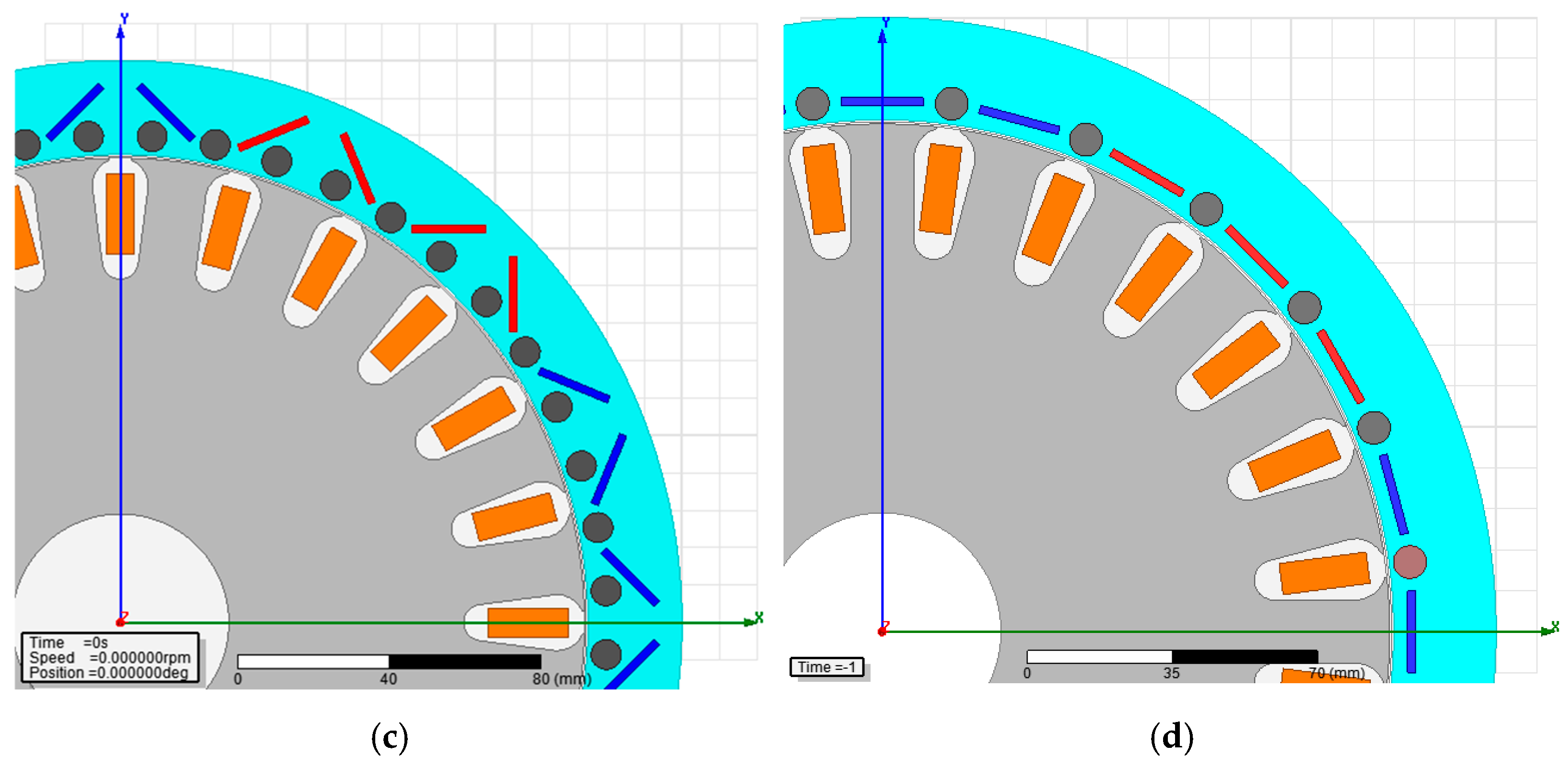
All research introduced to date, although many magnet alignment types have been proposed for the LSSM including inner rotor, only a few of them are suitable for outer rotor design as well because of the limited structural area of the rotor. In this study, LSSM models with 4 different types of magnet alignments for a medium voltage, low power electric vehicles were analyzed in the same inner stator configuration. All of these types analyzed by FEM are shown in Figure 2. Results obtained by the FEM analysis are evaluated and discussed in the next section.

3. 2D-FEM Analysis of the Outer Rotor Types

For evaluation of the analysis results, the performance of the structure types is discussed in many aspects. First, there is importance of the synchronization capability and startup performance related to the magnet alignments with different dimensions and placement of the bars. As better and fast synchronization reduces the rotor copper losses while keeping the speed at the desired value. The second aspect is the torque ripples which causes noises, torque harmonics and mechanical stress. Finally, the most important design criteria considered are holding at synchronous speed and asynchronous recovery without abandoning at high load angle of the PMSM. All of the analyses for all rotor types are realized by the same motor and load parameter, and these parameters are given in Table 4.
The 2D mesh model of the D-type motor consists of a total number of 33,526 elements. While 9841 elements are located in the rotor; 7789 elements exist in the stator. Each bar and magnet consists of 90 and 100 elements, respectively. The rest of the elements are located in the defined windings, band, inner-outer region and shaft region. Figure 3 shows the resulting mesh model of the Type-D motor.

3.1. Line-Startup Performance and Synchronization Capability

The magnets of different sizes for various rotor geometries were examined in terms of synchronization and line-startup performance at 110-V DC supply. When driving the motor by the inverter designed for this study, this supply voltage provided 77-V rms (phase to phase) without filters for delta connection of the stator winding.
As shown in Figure 4, the rotor Type-A with different magnet sizes settles at near synchronous speed. The startup performance of this type for each magnet size is low. Especially, it looks, a bad starting-up occurs under load. In addition to that, magnet length and thickness have no significant effects on startup and synchronization. The rotor Type-B with some magnet sizes settles at synchronous speed by oscillations and instability. The startup performance of this type for each magnet size is low, especially in large sizes. In addition, a bad starting-up and settling at synchronization under load with no stability. Where, magnet length and thickness have more notable effects on the transient and steady-state behavior. While the dimensions of 20-2/ 20-4/20-6 magnets result better performance in terms of keeping at synchronous speed, overshoot points at these magnets are higher than the weakness magnets ones. The rotor Type-C with some magnet sizes does not settle at synchronous speed in an acceptable time. Besides, the performance of the line-start depends on magnet size effectively. Start-up performance for the magnets in large sizes is low. In particular, the cogging torque effect of the large-size magnets appears to be dominant at start-up. However, small magnet sizes are suitable for this application, which is similar to the Type-A. The rotor Type-D for all magnet sizes reaches synchronous speed although having difficulties at low speed. In addition, start-up performance is the best in all sizes. While starting up, it has no negative speed oscillation and no instability. However, a drive system with control even open-loop may be needed to get a smooth response without overshoots and to get low oscillation without compromising a good synchronization. When the behaviors of these types under load are examined, which is given in next subsection, the rotor type of D gives good results for both synchronization and start-up with less cogging torque and better asynchronous recovery.

3.2. Asynchronous Recovery and Torque Ripples

All rotor types were analyzed under the rated load for line-start operation. In this analysis, the magnet size giving optimum result was selected in all types for a more realistic comparison. All of the simulation results by FEM are introduced in Figure 5 and Figure 6 for both transient and steady state behaviors of the motors.
Figure 5 shows the results of the rated load operation and Figure 6 shows the results of the relative overload operation. From these figures, it is observed that the Type-D motor is better than the others in terms of start-up performance, stability in steady-state behavior with low torque ripples and holding up the synchronization. Therefore, an OR-LSSM with the Type-D rotor was preferred to be implemented as a prototype. Although start-up performance of the Type-B was bad, it gave a relatively good performance with respect to the Type-A and Type-C. However, the Type-B motor has more oscillation at a synchronous speed and more torque ripples for a relative overload operation.

4. Prototype Implementation and Experimental Studies

Due to the start-up performance, stability in steady-state behavior with low torque ripples and holding up the synchronization, the Type-D motor was selected to make a prototype. For this purpose, the design parameters given in Table 4 were considered.
Firstly, inner stator laminations were processed and windings with pole pairs of four were placed into slots. Terminal cables were pulled out through the fixed shaft. Afterwards, outer rotor core laminations were prepared according to the preferred magnet and rotor bar alignment. Figure 7 shows all parts of the proposed design. The implemented parts of the outer rotor and inner stator are shown in Figure 8. In prototype implementation, 24-magnet (length: 20 mm, thickness: 2 mm) and 24-bar (diameter: 8 mm) were used. Also, magnets and rotor bars were positioned as N-bar-N-bar-N-bar-S-bar-S-bar-S-bar, per pole.
In order to carry out all experimental studies, a test platform including a power analyzer, electronic controlled load unit coupled with an alternator, switch mode power supply (SMPS) based direct current (DC) supply, torque and speed sensors coupled with the common shaft was prepared, as shown in Figure 9. An adaptive V/f based alternative current (AC) motor drive unit was designed, and implemented in this study for EVs.

4.1. Line-Start Operation without AC Drives

In general use, the proposed OR-LSSM can be used at low speed and high torque without a gearbox or at high speed and low torque with a load-bearing gear system. Therefore, this motor type must start-up easily with no load or under load. For this aim, the selected Type-D motor was started without any load until reaching synchronization speed. When the system reached stability, the rated load was applied for a while. Where the reference load torque was 10-Nm. For nominal loading, the system kept the speed at synchronous mode while producing the necessary torque. However, the motor did not meet the overload torque and a significant decrease in speed has also been observed. Since the motor could not remain in synchronous mode, it maintained asynchronous mode operation successfully. Also, when the overload was off, system settled to the synchronous speed similar to the rated loading. Obtained results from these operations, experimentally, are introduced in Figure 10 and Figure 11.
In Figure 11, the experimental result shows three operation parts: line start with no load, keeping synchronous speed under rated load and the last part is the rescue from the load. Since the rated load behavior tested before, at the end of the experiment, behavior of the proposed motor in transition from overload to the idle was presented. The aim of the operation is to observe the transient behavior of the sudden rescue from the load. So, it is seen that the proposed motor recovers itself and does not cause any oscillation while reaching to the synchronous speed.

4.2. Operation with AC Drives

It is essential to use an AC motor drive if this motor is used in an electric vehicle, which must be supplied from the battery. Therefore, it is necessary to test the proposed and prototyped motor with an AC motor drive. In this study, an adaptive boost voltage supplied V/f based AC motor drive was designed and realized for the experiments, as shown in Figure 9. The design details of this AC motor drive are not provided here in order to not distract the focus.
The speed and torque responses of the motor tested with the AC drive are presented in Figure 12. In addition, phase-to-phase stator voltage and phase current without any filter in delta connection are given in Figure 13. In this process, the torque reference was fully followed, and the speed was held at a synchronous speed without compromising. In this sense, the performance of the motor in terms of considered criteria was found to be in accordance with the proposed model design. Prototype motor provided synchronous speed for the load up to 10 Nm.
In Figure 13, rms value of the line current for unloaded condition is about 12-A in line voltage of 77-V like full reactive operation without rotor bar loses, and for relatively over loaded condition more about 20% is about 17-A at the same line voltage during mechanical power transformation. The power factor was able to increase up to 0.88 under the rated output power while it was low about 0.45 in unloaded operation. Also, the efficiency under the rated power was able to improve up to 87%.

5. Conclusions

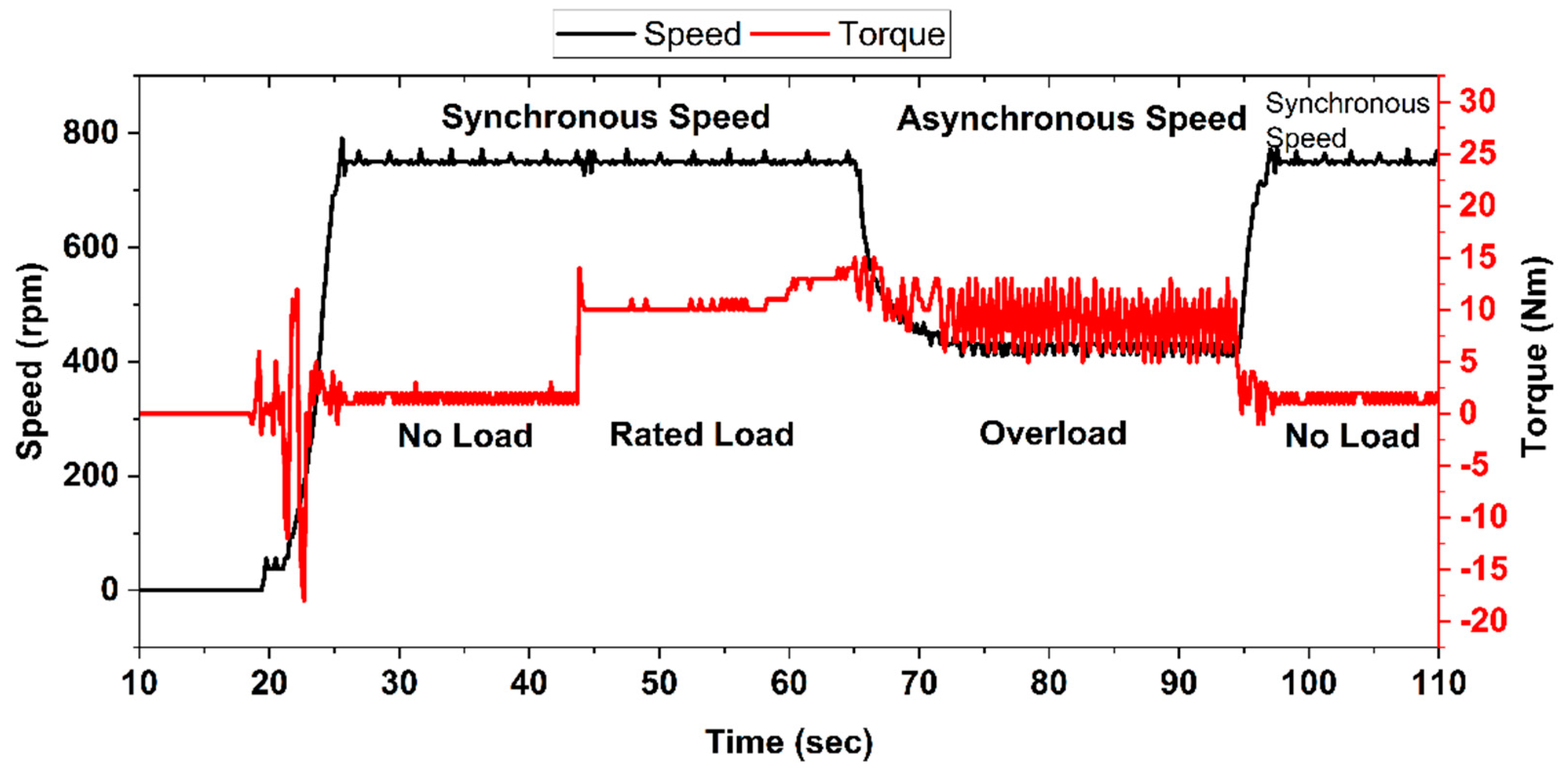
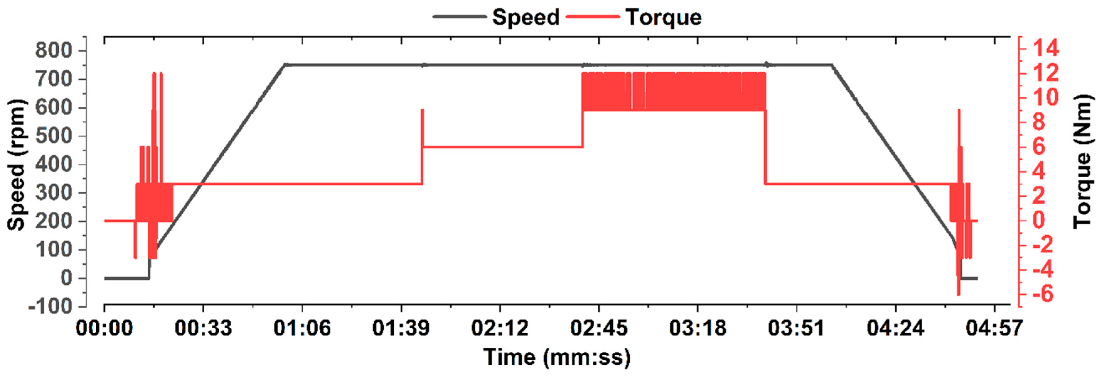
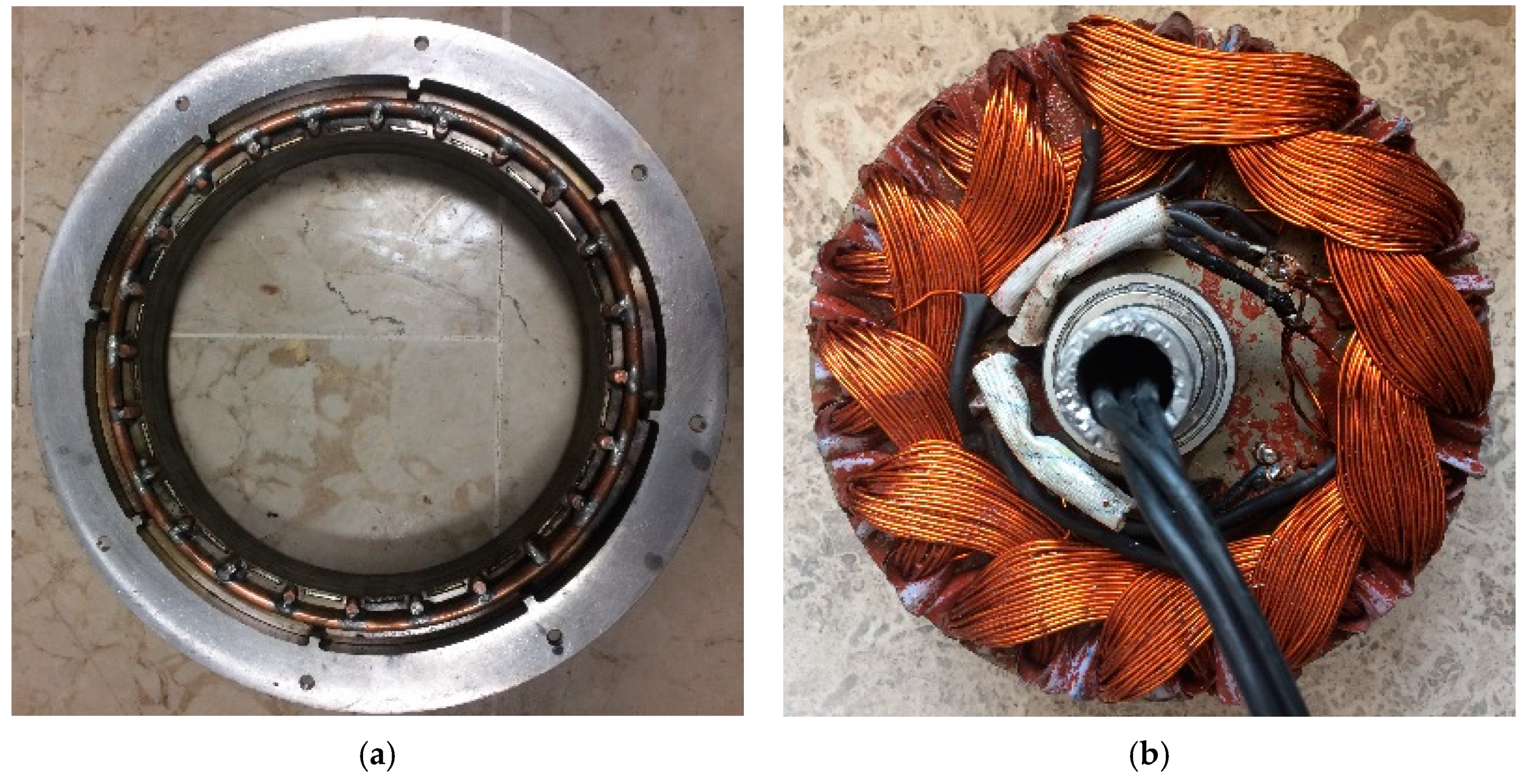
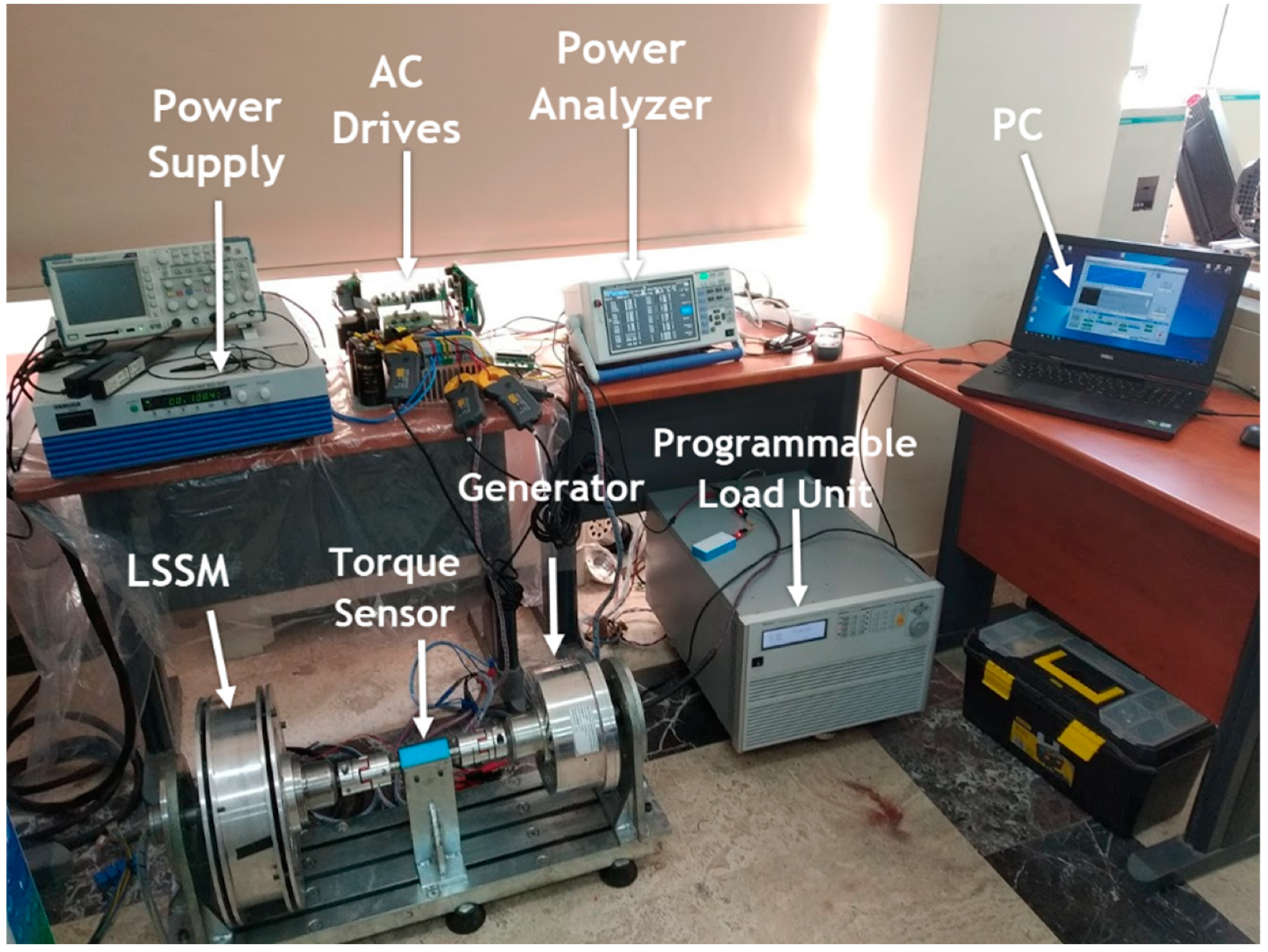
In this paper, instead of commonly used motors in electric vehicles, four different types of the outer rotor LSSM, which do not require any sensor and have no trouble in startup like a PMSM, have been designed and analyzed by FEM. The proposed novel motor model prototype which is the best model was implemented and experimental studies are presented.
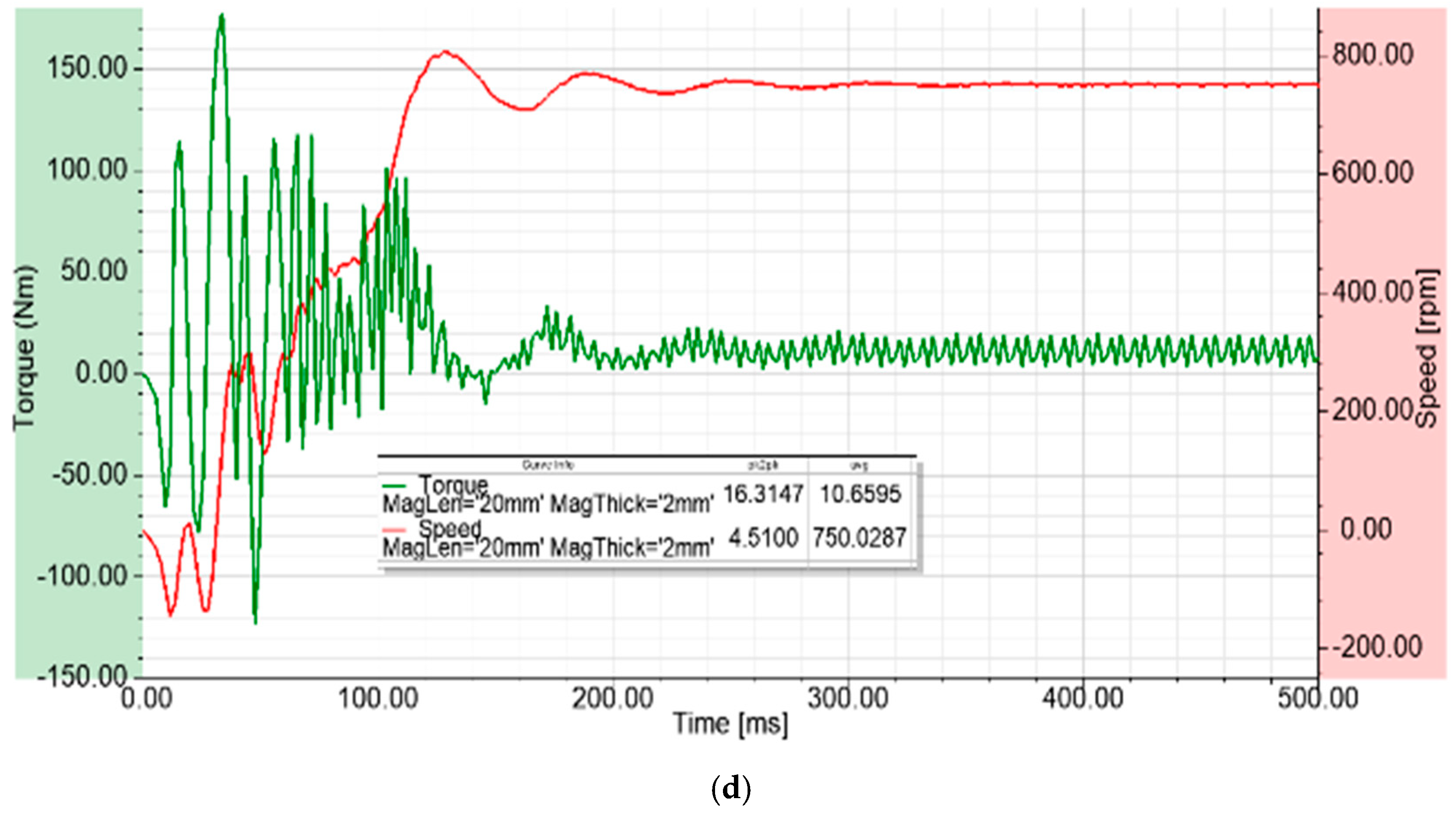
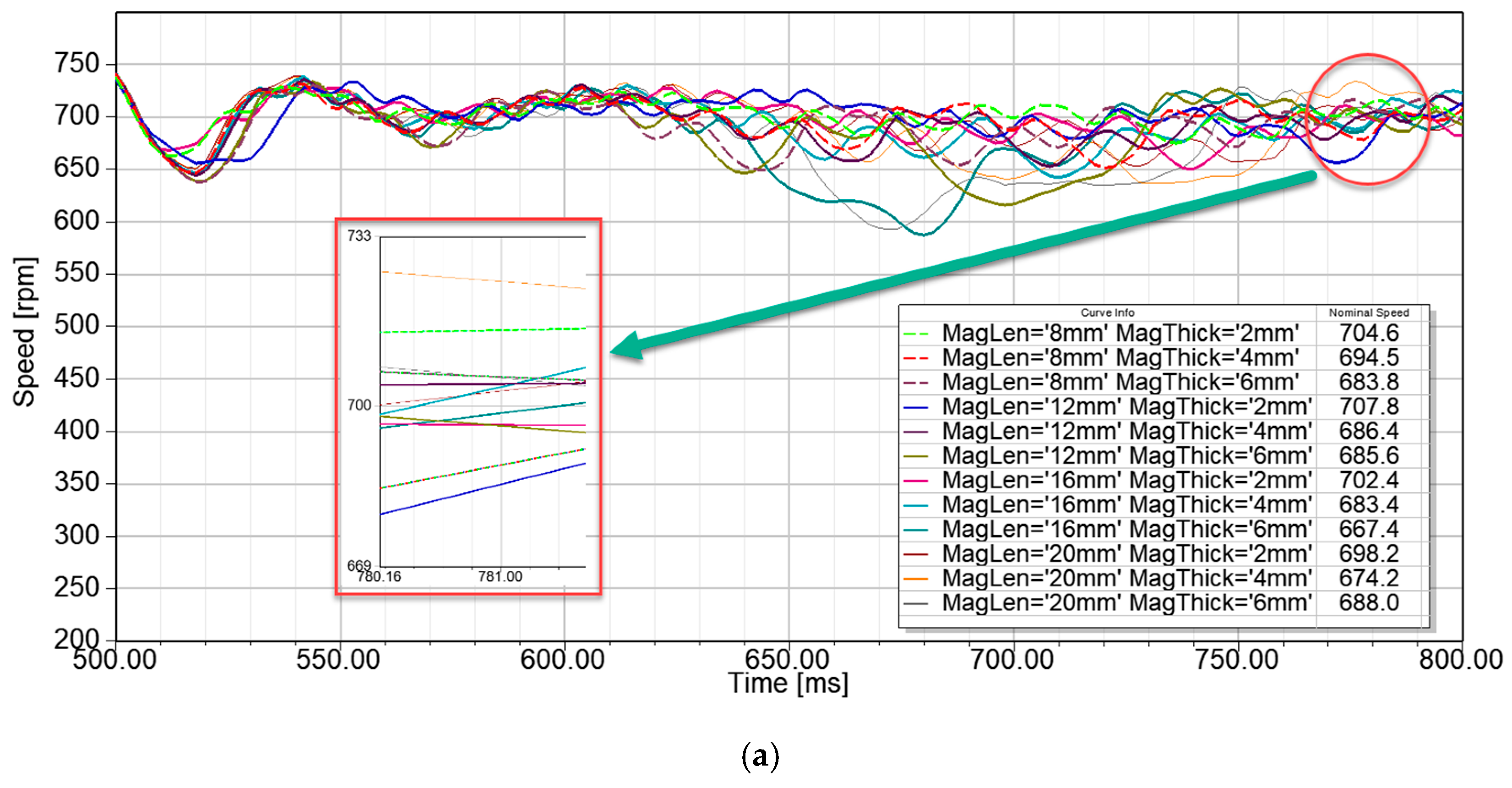
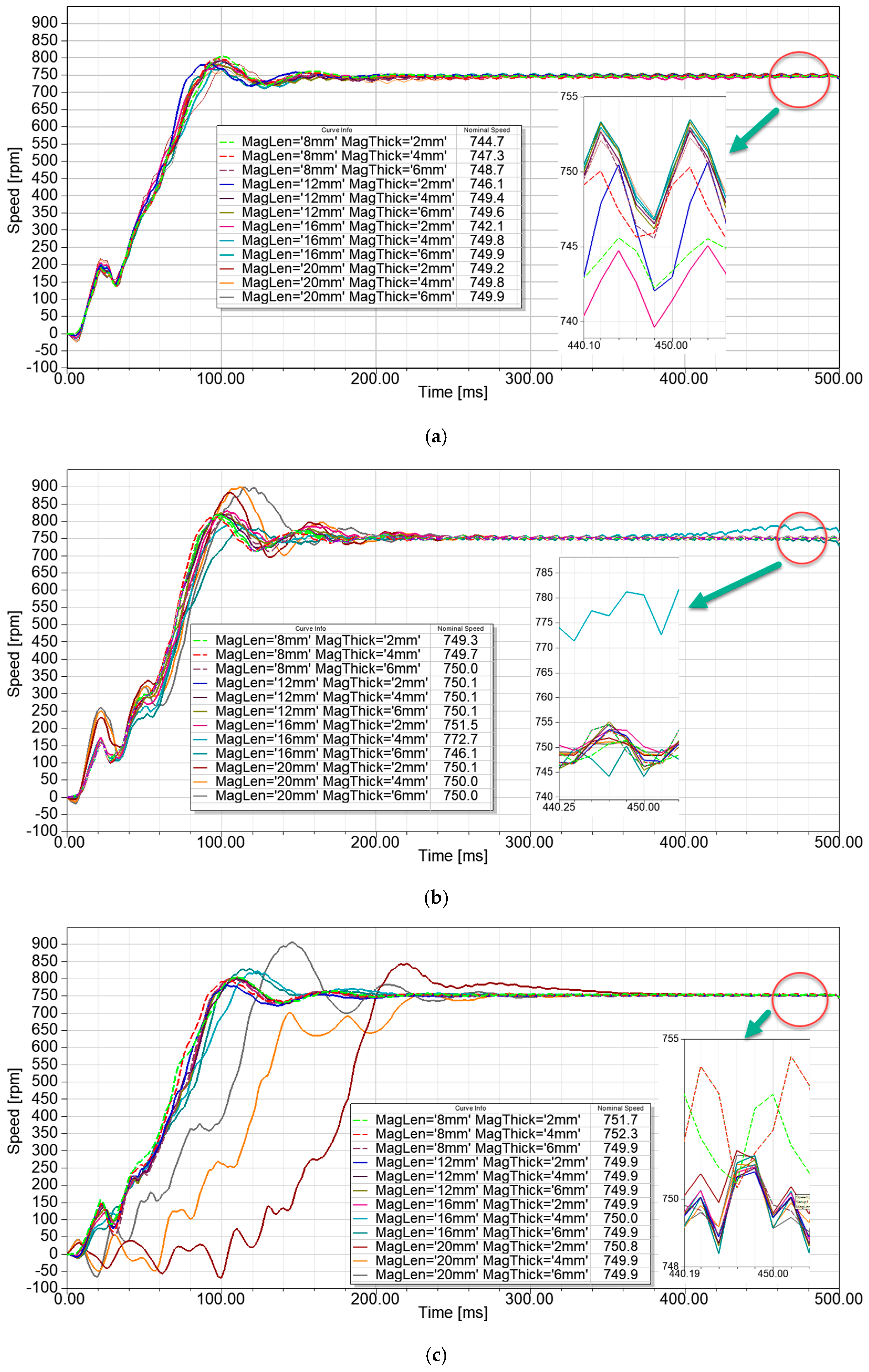
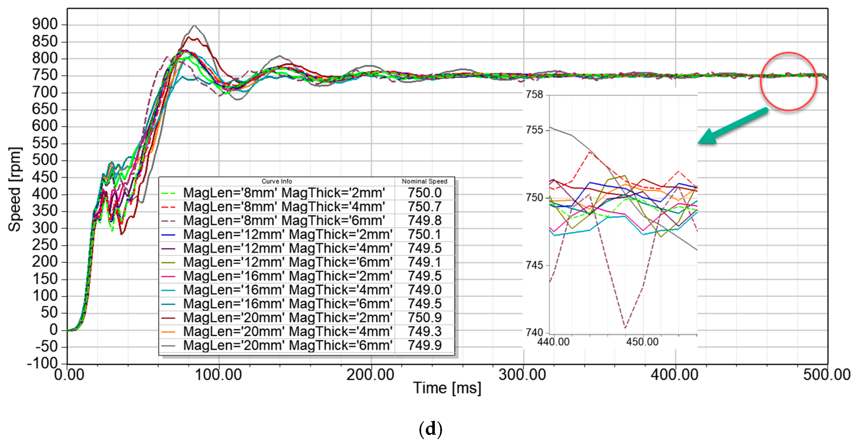
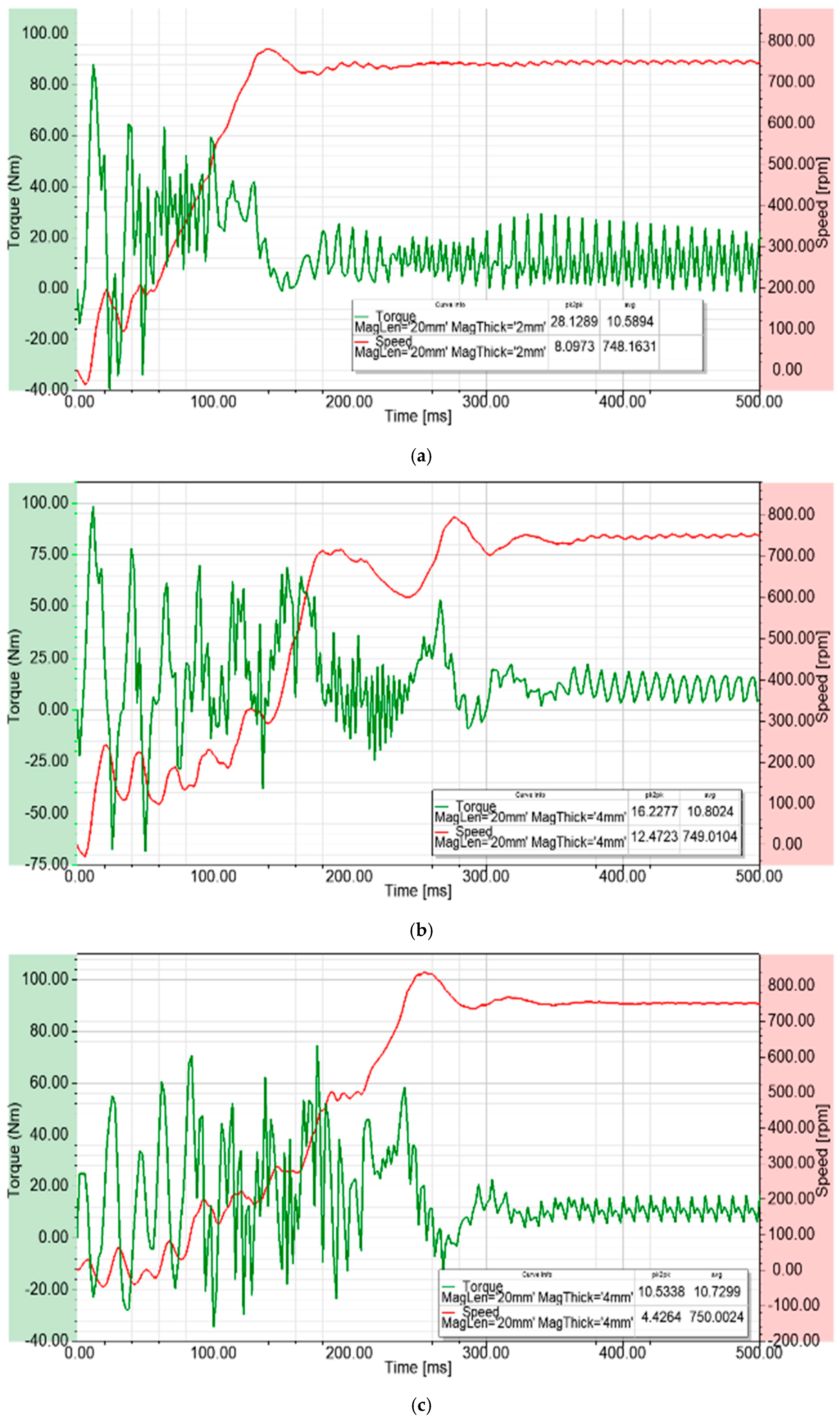
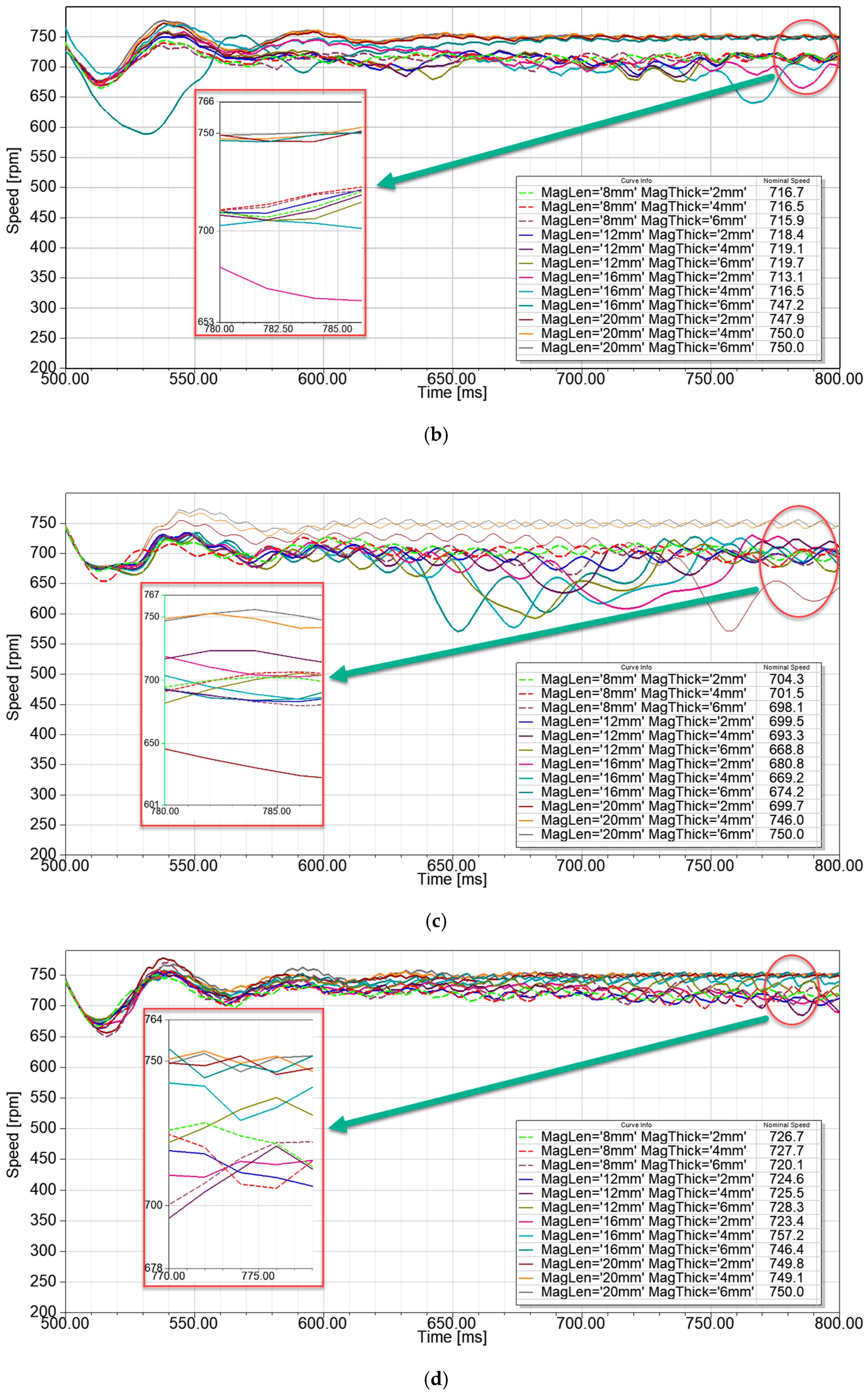
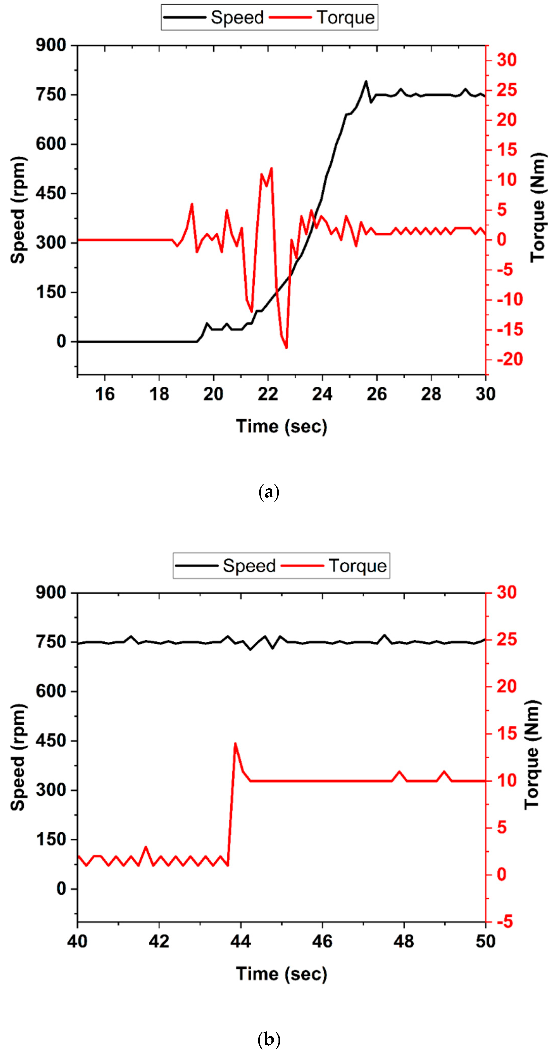
All motor types have been analyzed in terms of synchronization performance, starting performance and torque ripples with no load and under load. According to the findings obtained in this study, with no load, in terms of starting performance, the Type-D motor was 20% faster than the Type-B and C, but the same as the Type-A. When the motors were running under load, although the Type-D motor was the same as the Type-A, it was twice as fast as the B and C types, in terms of the settling time. Based on the torque ripple amplitude in steady-state, the Type-D motor had the lowest ripple amplitude with a low frequency. Although the Type-A motor was not stable, the torque ripple amplitude and frequency were three times higher than the Type-D. The Type-B and Type-C motors produced 70% lower torque ripple amplitude and frequency than the Type-A when continuously operating under load.
The obtained results from both the simulations and the experiments show that the proposed Type-D motor gives good performance at startup and produces fewer torque ripples by keeping the speed at the synchronous in case of working at the rated power. Under overload, the motor remained in asynchronous mode, thus ensuring the continuity of the system. This study demonstrated that the newly proposed outer rotor LSSM has the advantages of both synchronous motors and asynchronous motors. Thus, based on the above analysis and discussion, the proposed model can be used for EVs applications.

Author Contributions

Conceptualization, S.K., M.T.; methodology, S.K.; software, M.T.; validation, S.K., M.T.; formal analysis, M.T.; investigation, S.K., M.T.; resources, M.T., S.K.; data curation, M.T.; Performed the experiments and analyzed the data, M.T.; writing—original draft preparation, M.T.; writing—review and editing, S.K.; visualization, M.T.; supervision, S.K.; project administration, S.K.

Funding

This research received no external funding.

Acknowledgments

ANSYS Maxwell program for the FEM analysis is licensed by the university as an academic version.

Conflicts of Interest

The authors declare no conflict of interest.

References

  1. Larminie, J.; Lowry, J. Electric Vehicle Technology Explained, 2nd ed.; John Wiley & Sons Ltd.: Chichester, UK, 2012; ISBN 978-1-119-94273-3. [Google Scholar]
  2. Ehsani, M.; Gao, Y.; Gay, S.; Emadi, A. Modern Electric, Modern Hybrid, and Fuel Cell Vehicles; CRC Press: London, UK, 2005; ISBN 978-1-138-33049-8. [Google Scholar]
  3. Xue, X.D.; Cheng, K.W.E.; Cheung, N.C. Selection of Electric Motor Drives for Electric Vehicles. In Proceedings of the 2008 Australasian Universities Power Engineering Conference (AUPEC 08), Sdney, Australia, 14–17 December 2008; pp. 1–6. [Google Scholar]
  4. Zeraoulia, M.; Benbouzid, M.E.H.; Diallo, D. Electric motor drive selection issues for HEV propulsion systems: A comparative study. IEEE Trans. Veh. Technol. 2006, 55, 1756–1764. [Google Scholar] [CrossRef]
  5. Ehsani, M.; Gao, Y.; Miller, J.M. Hybrid electric vehicles: Architecture and motor drives. Proc. IEEE 2007, 95, 719–728. [Google Scholar] [CrossRef]
  6. Yang, Z.; Shang, F.; Brown, I.P.; Krishnamurthy, M. Comparative study of interior permanent magnet, induction, and switched reluctance motor drives for EV and HEV applications. IEEE Trans. Transp. Electrif. 2015, 1, 245–254. [Google Scholar] [CrossRef]
  7. Pellegrino, G.; Vagati, A.; Boazzo, B.; Guglielmi, P. Comparison of induction and PM synchronous motor drives for EV application including design examples. IEEE Trans. Ind. Appl. 2012, 48, 2322–2332. [Google Scholar] [CrossRef]
  8. Yuan, Y.; Meng, W.; Sun, X.; Zhang, L. Design Optimization and Analysis of an Outer-Rotor Direct-Drive Permanent-Magnet Motor for Medium-Speed Electric Vehicle. World Electr. Veh. J. 2019, 10, 16. [Google Scholar] [CrossRef]
  9. Lee, C.H.T.; Liu, C.; Chau, K.T. A magnetless axial-flux machine for range-extended electric vehicles. Energies 2017, 7, 1483. [Google Scholar] [CrossRef]
  10. Zhao, J.; Zheng, Y.; Zhu, C.; Liu, X.; Li, B. A novel modular-stator outer-rotor flux-switching permanent-magnet motor. Energies 2017, 10, 937. [Google Scholar] [CrossRef]
  11. Yao, Y.; Liu, C.; Lee, C. Quantitative comparisons of six-phase outer-rotor permanent-magnet brushless machines for electric vehicles. Energies 2018, 11, 2141. [Google Scholar] [CrossRef]
  12. Shu, Z.; Zhu, X.; Quan, L.; Du, Y.; Liu, C. Electromagnetic performance evaluation of an outer-rotor flux-switching permanent magnet motor based on electrical-thermal two-way coupling method. Energies 2017, 10, 677. [Google Scholar] [CrossRef]
  13. Lebkowski, A. Design, Analysis of the Location and Materials of Neodymium Magnets on the Torque and Power of In-Wheel External Rotor PMSM for Electric Vehicles. Energies 2018, 11, 2293. [Google Scholar] [CrossRef]
  14. Fei, W.; Luk, P.C.K.; Ma, J.; Shen, J.X.; Yang, G. A high-performance line-start permanent magnet synchronous motor amended from a small industrial three-phase induction motor. IEEE Trans. Magn. 2009, 45, 4724–4727. [Google Scholar] [CrossRef]
  15. Isfahani, A.H.; Vaez-Zadeh, S. Line start permanent magnet synchronous motors: Challenges and opportunities. Energy 2009, 34, 1755–1763. [Google Scholar] [CrossRef]
  16. Isfahani, A.H.; Vaez-Zadeh, S. Effects of magnetizing inductance on start-up and synchronization of line-start permanent-magnet synchronous motors. IEEE Trans. Magn. 2011, 47, 823–829. [Google Scholar] [CrossRef]
  17. Jedryczka, C.; Wojciechowski, R.M.R.M.; Demenko, A. Influence of squirrel cage geometry on the synchronisation of the line start permanent magnet synchronous motor. IET Sci. Meas. Technol. 2014, 9, 197–203. [Google Scholar] [CrossRef]
  18. Richter, E.; Neumann, T.W. Line start permanent magnet motors with different materials. IEEE Trans. Magn. 1984, 20, 1762–1764. [Google Scholar] [CrossRef]
  19. Zawilak, T. Utilizing the deep bar effect in direct on line start of permanent magnet machines. Prz. Elektrotechniczny 2013, 89, 177–179. [Google Scholar]
  20. Zöhra, B.; Akar, M.; Eker, M. Design of a novel line start synchronous motor rotor. Electronics 2019, 8, 25. [Google Scholar] [CrossRef]
  21. Kim, W.H.; Kim, K.C.; Kim, S.J.; Kang, D.W.; Go, S.C.; Lee, H.W.; Chun, Y.; Lee, J. A study on the optimal rotor design of LSPM considering the starting torque and efficiency. IEEE Trans. Magn. 2009, 45, 1808–1811. [Google Scholar] [CrossRef]
  22. Lee, B.; Hong, J.; Lee, J. Optimum design criteria for maximum torque and efficiency of a line-start permanent-magnet motor using response surface methodology and finite element method. IEEE Trans. Magn. 2012, 48, 863–866. [Google Scholar] [CrossRef]
  23. Shamlou, S.; Mirsalim, M. Design, optimisation, analysis and experimental verification of a new line-start permanent magnet synchronous shaded-pole motor. IET Electr. Power Appl. 2013, 7, 16–26. [Google Scholar] [CrossRef]
  24. Azari, M.N.; Mirsalim, M.; Pahnehkolaei, S.M.A.; Mohammadi, S. Optimum design of a line-start permanent-magnet motor with slotted solid rotor using neural network and imperialist competitive algorithm. IET Electr. Power Appl. 2016, 11, 1–8. [Google Scholar] [CrossRef]
  25. Sarani, E.; Vaez-zadeh, S. Design procedure and optimal guidelines for overall enhancement of steady-state and transient performances of line start permanent magnet motors. IEEE Trans. Energy Convers. 2017, 32, 885–894. [Google Scholar] [CrossRef]
  26. Mingardi, D.; Bianchi, N. Line-start PM-assisted synchronous motor design, optimization, and tests. IEEE Trans. Ind. Electron. 2017, 64, 9739–9747. [Google Scholar] [CrossRef]
  27. Sorgdrager, A.J.; Wang, R.; Grobler, A.J. Multiobjective design of a line-start PM motor using the Taguchi method. IEEE Trans. Ind. Appl. 2018, 54, 4167–4176. [Google Scholar] [CrossRef]
  28. Tumbek, M.; Kesler, S.; Oner, Y. Design and Fem Analysis of Low Voltage Outer Rotor Line Start Permanent Magnet Synchronous Motors with Different Magnet Alignments. In Proceedings of the 6th International Conference on Advanced Technology & Sciences (ICAT’Riga), Riga, Latvia, 12–15 September 2017; pp. 196–200. [Google Scholar]
  29. Toliyat, H.A.; Kliman, G.B. Handbook of Electrical Motors, 2nd ed.; CRC Press: London, UK, 2018; ISBN 978-0-824-741051. [Google Scholar]
  30. Sawhney, A.K. Electrical Machine Design, 1st ed.; Dhanpat Rai & Sons: Delhi, India, 1984. [Google Scholar]
Figure 1. Design procedure of an OR-LSSM.
Energies 12 03174 g001
Figure 2. Rotor types for different alignments and orientations of the magnets with bars. (a) Type-A: Axial alignment., (b) Type-B: Radial alignment, (c) Type-C: Cross alignment, (d) Type-D: Axial alignment with bar in-lined.
Energies 12 03174 g002aEnergies 12 03174 g002b
Figure 3. Motor design descriptions, (a) 2D mesh model of the Type-D, (b) definition of the bar and magnet dimensions.
Energies 12 03174 g003
Figure 4. Performance of the motor types for different magnet sizes. (a) Type-A, (b) Type-B, (c) Type-C, (d) Type-D.
Energies 12 03174 g004aEnergies 12 03174 g004b
Figure 5. Simulation results for line-start and steady-state operation under the rated load (10 Nm) for optimum magnet size of each configuration. (a) Type-A, (b) Type-B, (c) Type-C, (d) Type-D.
Energies 12 03174 g005aEnergies 12 03174 g005b
Figure 6. Transient and steady state behavior of all types under a relative overload. (a) Type-A, (b) Type-B, (c) Type-C, (d) Type-D.
Energies 12 03174 g006aEnergies 12 03174 g006b
Figure 7. All parts of the proposed motor design.
Energies 12 03174 g007
Figure 8. Prototype motor for the Type-D configuration (a) outer rotor (b) inner stator.
Energies 12 03174 g008
Figure 9. Experimental setup.
Energies 12 03174 g009
Figure 10. Experimental results of the Type-D rotor configuration for both no load and under rated load. (a) Line-startup with no load operation. (b) Application of 10 Nm for rated power.
Energies 12 03174 g010
Figure 11. Synchronous operation at the rated load and asynchronous operation mode under overload.
Energies 12 03174 g011
Figure 12. Experimental results for loading up to the rated torque: Speed and torque response of the motor controlled by AC motor drives.
Energies 12 03174 g012
Figure 13. Line-to-line stator voltages and line currents wave throughout the AC motor drive. (a) with no load condition. (b) under the relatively over load more about 20%.
Energies 12 03174 g013
Table 1. Fundamental parameters of motor design.
ParameterDefinitionDescriptionEq.
f p n s 2 Frequency(1)
ϕ B av π DL p Flux in the air gap per pole(2)
T ph ac × π D 6 Number of turns per phase(3)
D 2 L Power [ kVA ] C 0 n s Power per rps related to per volume degree(4)
C 0 1.11 × π 2 × K w × B av × ac × 10 3 Esson’s constant(5)
Table 2. Definition of the stator parameters.
ParameterDefinitionDescriptionEq.
I s Power [ kVA ] × 1000 3 E s Stator current per phase(6)
a s I s δ s Cross-sectional area of the conductors(7)
S s 2 M × g s × p Total number of slots(8)
Y ss π D S s Stator slot pitch(9)
Z ss 6 × T ph S s Total number of the conductors(10)
L g 0.2 + 2 ( DL ) Air gap length (mm)(11)
Table 3. Definition of the rotor parameters.
ParameterDefinitionDescriptionEq.
Y sr π D S r Rotor slot pitch(12)
g r S r 2 p Number of slots per phase(13)
Rotor   MMF ( 0.85 ) ×   Stator   MMF Rotor magneto-motor force(14)
I b . S r 2 ( 0.85 ) × ( 3 × I s × T ph ) Current per rotor conductor bar(15)
A b I b δ b Cross-sectional area of the rotor bar(16)
I e S r I b π p End ring current(17)
A e I e δ e   ( mm 2 ) Cross-sectional area of the rotor bars’ end ring(18)
Table 4. Design parameters for all types.
ParameterValue
Rated Power at synchronous speed 1.0 HP, 750 rpm
Asynchronous Peak Power1.2 HP, 500 rpm
Rated speed 750 rpm
Pole-Pair4
Operational Mode (Duty class)S1
Rated Torque10 Nm, 750 rpm
Overload Asynchronous Speed400 rpm

