Article

Study on Fault Current Characteristics and Current Limiting Method of Plug-In Devices in VSC-DC Distribution System

1
School of Electric Power, South China University of Technology, Guangzhou 510640, China
2
Shenzhen Power Supply Corporation, China Southern Power Grid, Shenzhen 518048, China
*
Author to whom correspondence should be addressed.
Energies 2019, 12(16), 3159; https://doi.org/10.3390/en12163159
Submission received: 19 June 2019 / Revised: 10 August 2019 / Accepted: 14 August 2019 / Published: 16 August 2019

Abstract

:
The DC (Direct Current) distribution system based on the voltage source converter (VSC-DC) has become a research hotspot due to its various advantages. There are many plug-in devices in the VSC-DC distribution system, which may be damaged by the fault current. Therefore, studying the fault current characteristics and current limiting method is one of the key methods to ensure the safe and stable operation of the VSC-DC distribution system. Based on theoretical analysis and simulation calculations, this paper studies the causes, influencing factors, and current limiting methods of the fault current when the pole-to-pole fault occurs at the line side of plug-in devices in a ±10 kV VSC-DC distribution system. Firstly, based on the system topology, the decisive fault condition of fault current and the design principle of current limiting reactor value are analyzed. Secondly, the theoretical calculation methods of fault current and current limiting reactor value which satisfies the breaking capacity of DC circuit breaker are proposed. Finally, the accuracy of theoretical calculation methods is verified by simulation in PSCAD/EMTDC (Power Systems Computer Aided Design/Electromagnetic Transients including DC). The research results could provide the theoretical calculation methods of the fault current and the current limiting reactor value of plug-in devices in the ±10 kV VSC-DC distribution system.

1. Introduction

The DC distribution system based on the voltage source converter is advantageous to realize the renewable energy grid connection and consumption, sensitive electronic loads, and electric vehicles connection, etc. It will become one of the key technologies of smart energy and smart city development trend in the future [1,2]. At present, many ±10 kV VSC-DC distribution projects have been taken into application, such as Guizhou, Hangzhou, Zhangbei, Zhuhai ±10 kV VSC-DC distribution projects in China [3].
At present, there are still many basic scientific problems and key technologies concerning the VSC-DC distribution system that remain to be studied in depth. When the pole-to-pole fault occurs in the system, the fault current will rise rapidly due to the large-scale parallel capacitors. The capacitors installed in the converters will discharge directly through the short circuit point, which has a negative effect on the safe and reliable operation of the equipment and distribution power grid system. Therefore, studying on the fault current characteristics and current limiting method are of great significance for the design of the equipment, the control and protection strategy of the distribution system, etc.
At present, devices to isolate the DC faults mainly include AC (Alternating Current) circuit breakers, sub-modules with DC fault clearing capability, and DC circuit breakers [4]. Among them, AC circuit breakers have a longer operation time, which will expose power electronic devices to a larger fault current for a longer time and will also increase the time for the system to recover its power supply. The modified sub-modules with DC fault clearing capabilities will increase the loss and investment in steady state operation and complicate the control of the system at the same time. However, the DC circuit breakers have the advantages of fast operation speed and high reliability of system power supply. Therefore, using DC circuit breakers for fault isolation is an ideal choice in the VSC-DC system at present, and it is the major developing tendency. A living example is the Nan’ao multi-terminal VSC-DC project, which has installed DC circuit breakers to achieve fault isolation [5,6,7,8].
However, DC circuit breakers have low breaking capacity, which means that it cannot break a high fault current [9,10,11,12,13]. Therefore, it is necessary to limit the fault current within the DC breakers’ breaking capacity by corresponding current limiting measures. Common current limiting methods include the use of series-connected inductance current limiter [14,15,16] and resistance current limiter [17,18,19,20], such as series current limiting reactor and superconducting current limiter. The principle of current limiting methods is to reduce the fault current by increasing the fault circuit impedance. At present, the simple and economical current limiting reactor is mainly adopted to limit the fault current [14,21].
Studying the causes of fault current and its electromagnetic transient characteristics can provide the theoretical basis for the design of system protection strategy and current limiting reactor. The study on fault current characteristics for a system protection strategy is based on a determined current limiting reactor, which cannot provide reference for the current limiting reactor selection [22,23,24,25]. However, there are still two deficiencies in the researches on current limiting methods [26,27,28,29,30]:
(1)
The study on current limiting methods mainly focuses on the aspect of a single VSC converter when the pole-to-pole fault occurs at the line side. However, the interaction and protection methods of main converters and plug-in devices, which are connected to the medium voltage DC line, are neglected when the fault occurs.
(2)
The study on current limiting methods of VSC converter mainly focuses on the main converter. However, the voltage level at the load side of the plug-in device is low, and the process of fault discharge is different from the main converter.
The reference [15] simulated and analyzed the fault current under the pole-to-pole fault at the line side of plug-in devices and selected the value of current limiting reactor. However, it did not propose any methods to select the value of current limiting reactor when the multiple plug-in devices were connected to the system.
Therefore, it is necessary to study the fault current electromagnetic transient characteristics and the current limiting method for the safe and stable operation of the plug-in devices and the whole system. The study is also useful for the protection strategy of plug-in devices [29,30]. Firstly, this paper analyzes and proposes the design principle of current limiting reactor value based on a VSC-DC distribution system, as the design scheme of Shenzhen Baolong Industrial Park [31,32]. Secondly, the causes of fault current are analyzed, and the theoretical calculation methods of fault current of plug-in devices are deduced. Thirdly, combined with the breaking capacity of medium voltage DC circuit breaker, the calculation methods of current limiting reactor value are proposed. At last, the electromagnetic transient simulations are carried out to verify the theoretical calculation methods of the fault current value and the current limiting reactor value. The value of fault current and current limiting reactor can be obtained quickly by the theoretical calculation methods in this paper, which has certain guiding significance for the construction of subsequent practical projects.

2. System Topology and Design Principle of Current Limiting Reactor Value

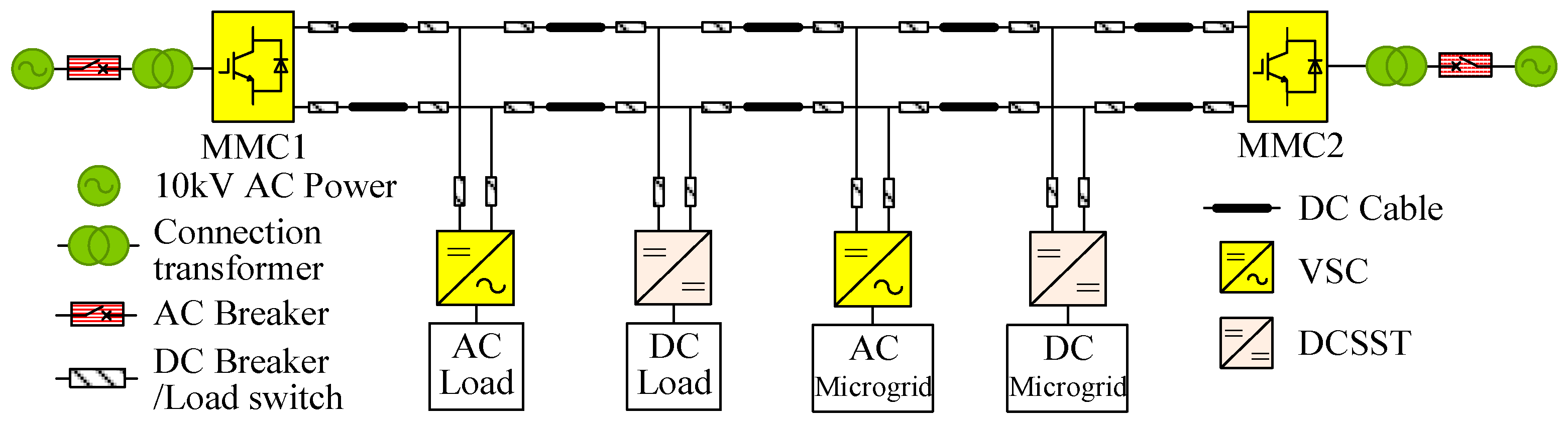
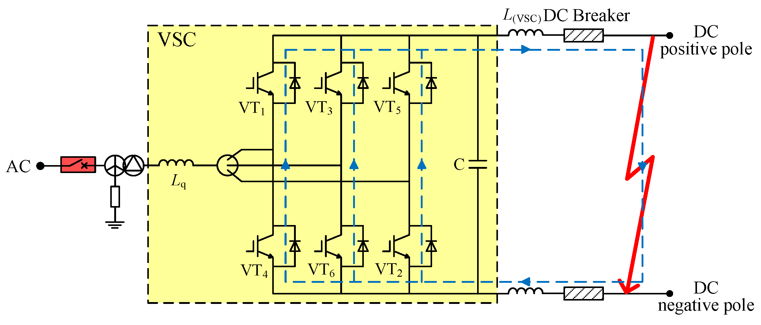
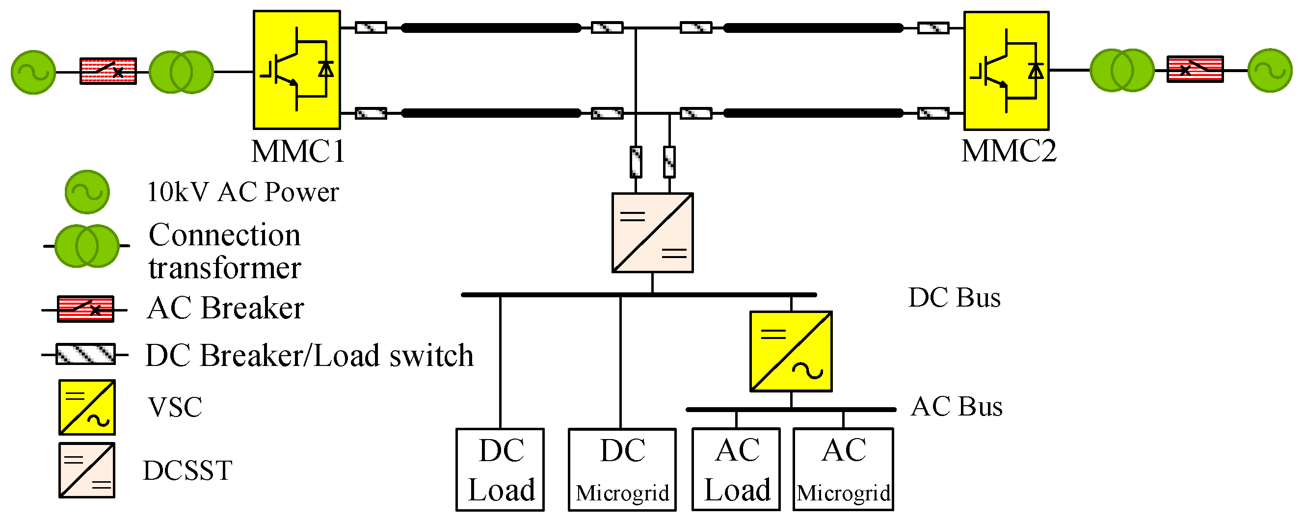
2.1. DC Distribution System Topology

The topology structure of the ±10 kV VSC-DC distribution system is shown in Figure 1. The system adopts ±10 kV unipolar symmetrical wiring method, and the loads are connected to the ±10 kV DC line through corresponding plug-in devices.
System access loads include AC load, AC micro-grid, DC load, and DC micro-grid. Among them, the AC load and the AC micro-grid are connected to the ±10 kV DC cable through the two-level VSC converter. The DC load and the DC micro-grid are connected to the ±10 kV DC cable through the DC-DC transformer DCSST (DC Solid State Transformer) [31,32].

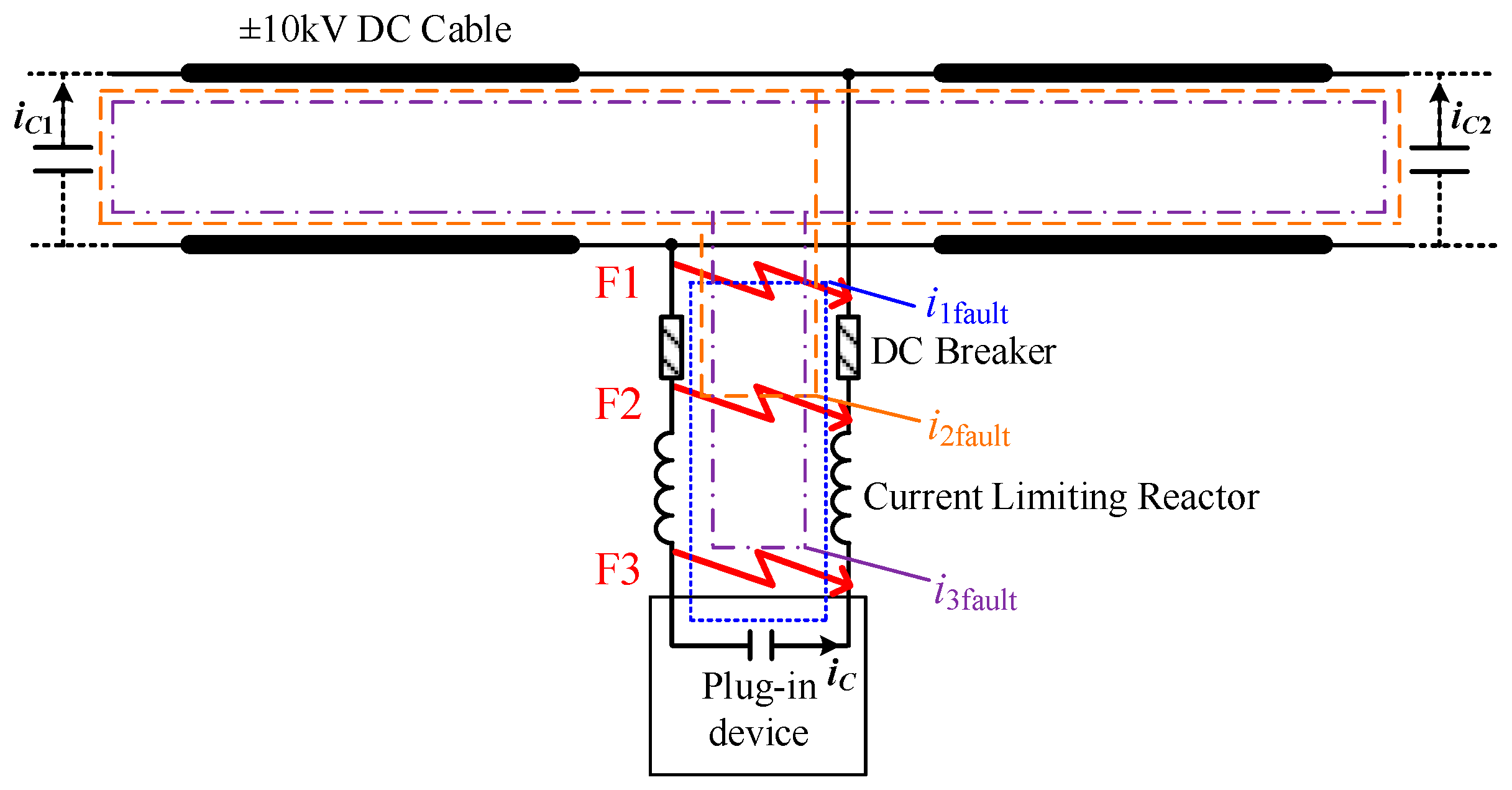
2.2. Design Principle of Current Limited Reactor Value

The typical pole-to-pole faults at the line side of plug-in devices of the VSC-DC distribution system are shown in Figure 2. In order to ensure that the DC circuit breaker can isolate the faults, the current limiting reactor should limit the fault current through the DC circuit breaker within its breaking capacity.
When the F1 pole-to-pole fault occurs, the fault current through the DC circuit breaker ifault is the discharge current iC, which is the discharge current of the capacitor at the line side of plug-in device (i1fault = iC in Figure 2). While in F2 or F3 pole-to-pole faults, the fault current through the DC circuit breaker ifault is the sum of the discharge current from other devices’ capacitors (i2,3fault = iC1 + iC2 + … in Figure 2). Therefore, the more devices connect in the ±10 kV DC cable, the higher the fault current through the DC circuit breaker under F2 or F3 faults will be. Thus, the current limiting reactor value should be designed when all devices in the system are put into operation.
Compared with F3 fault, the fault current from other devices under F2 fault does not flow through the current limiting reactor of the plug-in device, so the fault current in F2 is more serious.
Therefore, only the F1 and F2 faults need to be considered when the limiting reactor value is designed, and the following two conditions should be satisfied:
(1)
For F1 fault: the current limiting reactor should limit the discharge current from the capacitor at the line side of the plug-in device within the breaking capacity of the DC circuit breaker.
(2)
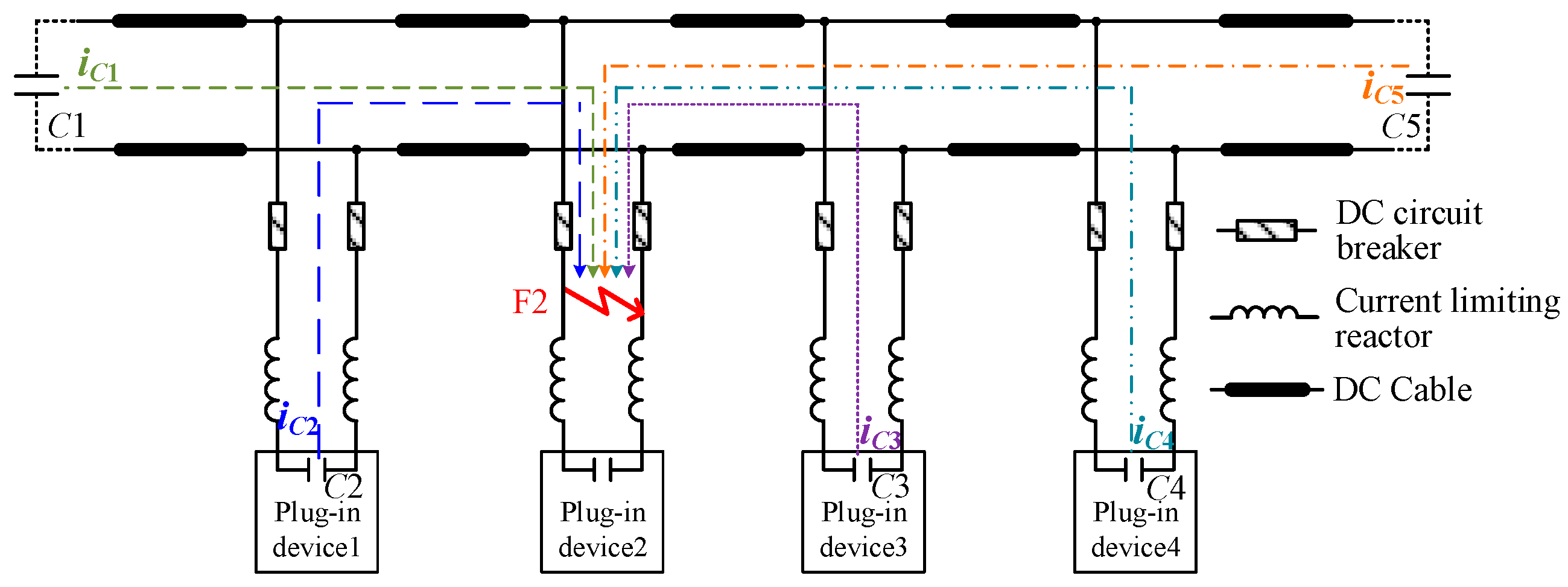
For F2 fault: the sum of discharge current from the other device’s capacitors should be limited to the breaking capacity of the DC circuit breaker.

3. Causes of Fault Current and Design Method of Current Limiting Reactor Value

3.1. F1 Pole-To-Pole Fault

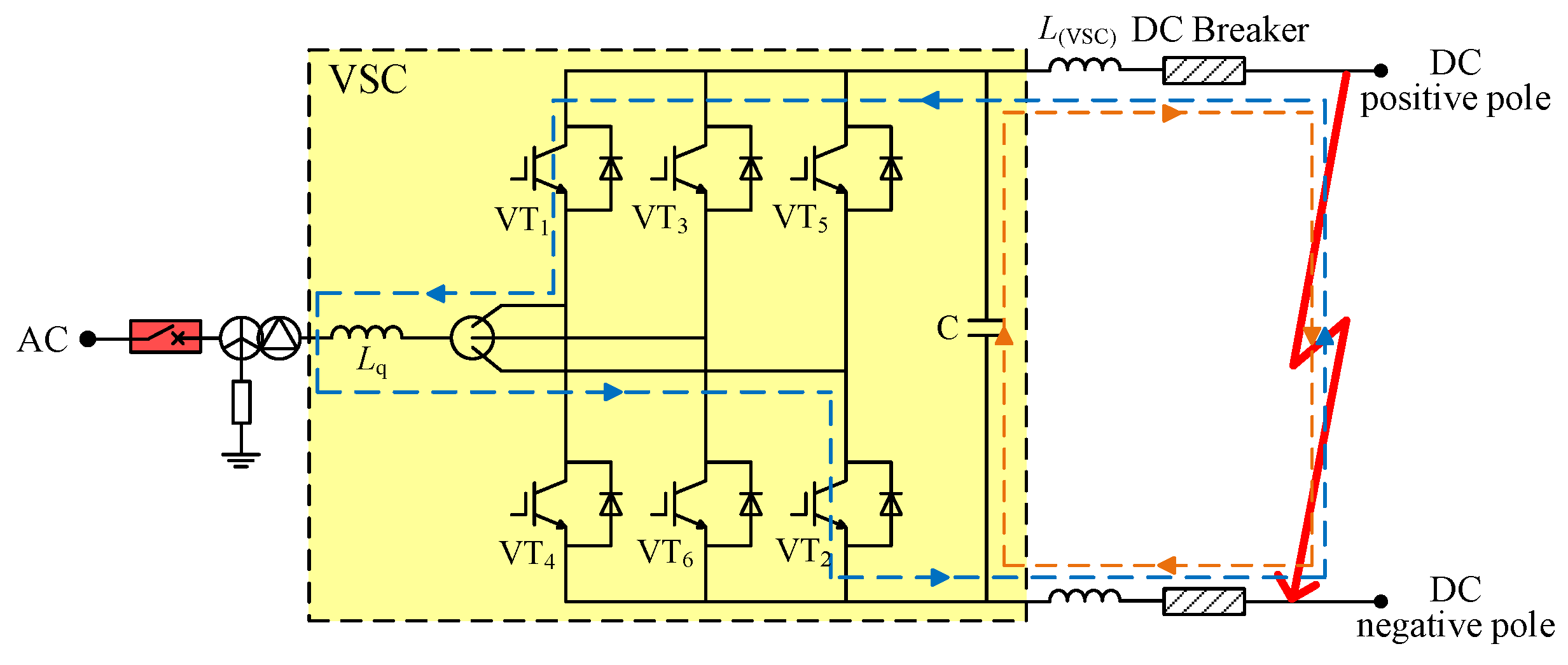
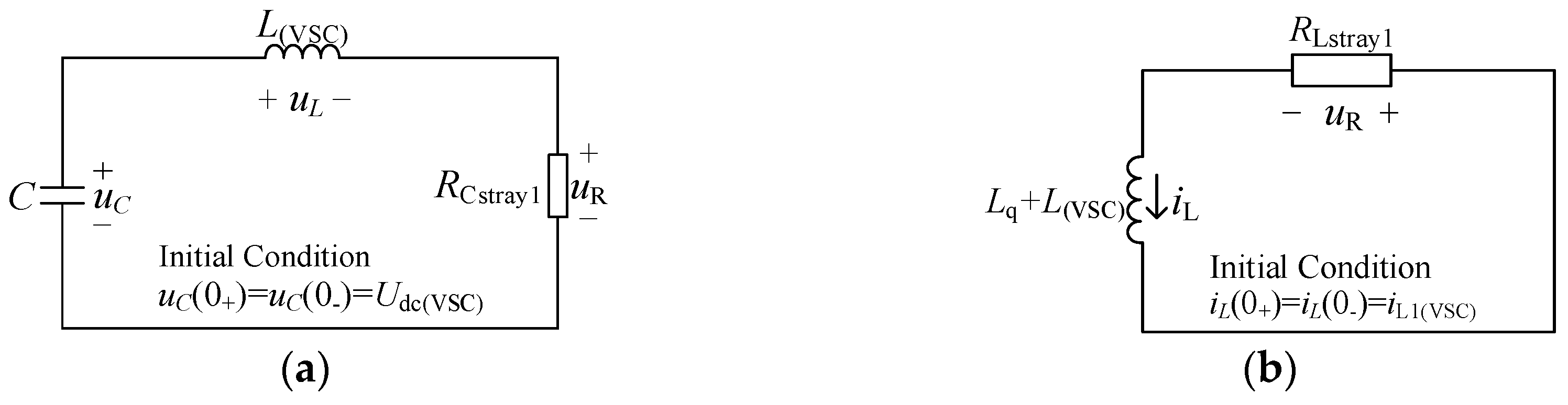
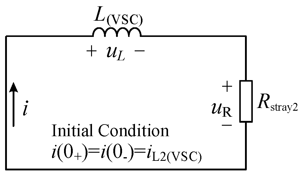
3.1.1. Analysis of Pole-To-Pole Fault Current at the Line Side of VSC

When the plug-in device adopts VSC converter, AC load, and the low voltage AC micro-grid are connected to the ±10 kV DC cable through the VSC. For AC load, it will not discharge to the fault point after the fault, while for the AC micro-grid, compared with 10 kV, its voltage level is lower. At the same time, the discharge current is further reduced due to the impedance of transformer and the bridge arm inductor, so the discharge current can be neglected. Therefore, the fault development process can be divided into two stages when the F1 fault occurs at its line side.
The first stage, capacitor discharge stage: Because the discharge current of VSC load side is very low, and the current flowing through IGBT is similar with the normal operation, it will not cause IGBTs blocking. The blocking of IGBTs occurs when the DC circuit breaker operates. It is still necessary to consider the discharge of bridge arm reactor to the fault point. Therefore, the line side capacitor and the bridge arm inductor discharge through the fault point. The fault discharge circuit is shown in Figure 3. The fault discharge process can be superimposed by the second-order circuit of the capacitor–inductor and the first-order circuit of the inductor, as shown in Figure 4.
In Figure 4, Rstray1 is the equivalent resistance of the first stage discharge circuit (where the capacitor discharge circuit equivalent resistance RCstray1(VSC) = RC + RL + RDCB + Rf, bridge arm inductor discharge circuit equivalent resistance RLstray1(VSC) = RLq + RIGBT + RL + RDCB + Rf), C is the line side capacitor of VSC, L(VSC) is the current limiting reactor, Lq is the bridge arm reactor, Udc is the voltage of capacitor, and iL1(VSC) is the line current.
The second stage, inductor freewheeling stage: when the voltage of the capacitor crosses zero, the reverse voltage applied to the diodes disappears and the diodes are turned on, as shown in Figure 5. When the energy stored in the current limiting reactor is exhausted, the fault discharge process ends. The equivalent circuit of the inductor freewheeling stage is shown in Figure 6.
In Figure 6, Rstray2 is the equivalent resistance of the second stage discharge circuit (Rstray2(VSC) = RD + RL + RDCB + Rf), L(VSC) is the current limiting reactor, and iL2(VSC) is the instantaneous fault current before the start of the second stage.
The fault current calculation methods in different stages can be obtained from the fault equivalent circuit:
The first stage, capacitor discharge stage: the fault current iF1(VSC) is given by
i F 1 ( VSC ) = i C ( VSC ) i L ( VSC ) = e δ t U dc ( VSC ) ω L ( VSC ) sin ( ω t ) i L 1 ( VSC ) e t ( L ( VSC ) + L q ) / R Lstray 1 ( VSC )
where δ = R Cstray 1 ( VSC ) 2 L ( VSC ) , ω = 1 L ( VSC ) C ( VSC ) ( R Cstray 1 ( VSC ) 2 L ( VSC ) ) 2 .
The second stage, inductor freewheeling stage: the fault current iF1(VSC) is given by
i F 1 ( VSC ) = i L 2 ( VSC ) e t L ( VSC ) / R stray 2 ( VSC )
where i L 2 ( VSC ) = e δ t C U dc ( VSC ) ω L ( VSC ) sin ( ω t C ) i L 1 ( VSC ) e t C ( L ( VSC ) + L q ) / R Lstray 1 ( VSC ) .
The time of capacitor voltage crossing zero is given by
t C = [ π arctan ( ω δ ) ] / ω
From the analysis above, it can be seen that the rising stage of fault current under F1 fault is the capacitor discharge stage, and the decaying stage is the inductor freewheeling stage. Therefore, to limit the magnitude and the rising rate of the fault current, the capacitor discharge stage should be limited. The breaking capacity of the DC circuit breaker has two influencing factors: the maximum breaking current, IDCB, and the maximum breaking time, tDCB. The DC circuit breaker can break the maximum fault current IDCB within the time tDCB (including fault identification time and breaking time). The relationship between IDCB (tDCB), VSC line side capacitor, and current limiting reactor (C, L(VSC)) can be obtained from (1), and the calculation results are shown in Figure 7.
Figure 7 shows that the larger the capacitor or the smaller the current limiting reactor value is, the higher the fault current that flows through the DC circuit breaker will be. However, as the current limiting reactor increases, the effect of the capacitor on the fault current is reduced. Therefore, the value of current limiting reactor is the major factor affecting the fault current. It is more effective to limit the fault current by increasing the current limiting reactor value. In order to make the fault current satisfy breaking capacity of the DC circuit breaker (assuming IDCB = 10 kA within tDCB = 5 milliseconds), the parameters of the capacitor of VSC and current limiting reactor (C, L(VSC)) should be in the blank area of Figure 8. It is found that when the breaking current IDCB of DC circuit breaker goes higher, the current limiting reactor value can be lower.
Therefore, when the F1 fault occurs at the line side of the VSC, in order to limit the fault current to the breaking capacity of the DC circuit breaker, the fault current iF1(VSC) should satisfy (4) in the capacitor discharge stage after the current limiting reactor LF1(VSC) is installed to the VSC.
i F 1 ( VSC ) = e δ t U dc ( VSC ) ω L F 1 ( VSC ) sin ( ω t ) i L 1 ( VSC ) e t ( L F 1 ( VSC ) + L q ) / R Lstray 1 ( VSC ) I DCB ( t t DCB )
where δ = R Cstray 1 ( VSC ) 2 L F 1 ( VSC ) , ω = 1 L F 1 ( VSC ) C ( VSC ) ( R Cstray 1 ( VSC ) 2 L F 1 ( VSC ) ) 2 .

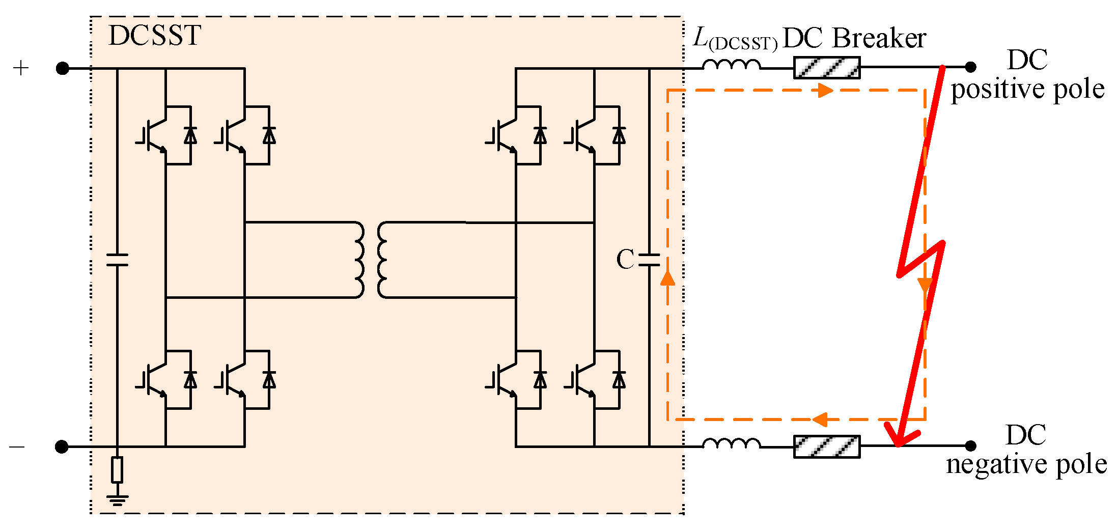
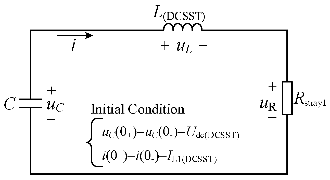
3.1.2. Analysis of Pole-To-Pole Fault Current at the Line Side of DCSST

When the plug-in device uses DCSST converter, the structure of which adopts high-frequency-link DC transformer topology (the equivalent topology structure is shown in reference [30]), the multiple modularization schemes are in the form of input series output parallel (ISOP) [33,34]. When F1 fault occurs at its line side, the fault development process is similar to VSC and can also be divided into two stages.
The first stage, capacitor discharge stage: compared with the VSC capacitor discharge process, there is no bridge arm inductor discharge process in DCSST, so that the fault discharge process is only equivalent to the second-order circuit of capacitor–inductor. The fault discharge circuit is shown in Figure 9. The fault discharge process can be superimposed by the second-order circuit of the capacitor–inductor, as shown in Figure 10.
The second stage, inductor freewheeling stage: when the voltage of the capacitor crosses zero, the current limiting reactor will freewheel through the diode. The equivalent circuit is shown in Figure 7.
The fault current calculation methods in different stages can be obtained from the fault equivalent circuit:
The first stage, capacitor discharge stage: the fault current is given by
i F 1 ( DCSST ) = e δ t [ U dc ( DCSST ) ω L ( DCSST ) sin ( ω t ) ω 0 i L 1 ( DCSST ) ω sin ( ω t β ) ]
where δ = R stray 1 ( DCSST ) 2 L ( DCSST ) , ω = 1 L ( DCSST ) C ( DCSST ) ( R stray 1 ( DCSST ) 2 L ( DCSST ) ) 2 , ω 0 = 1 L ( DCSST ) C ( DCSST ) , β = arctan ( ω δ ) .
The second stage, inductor freewheeling stage: the fault current is given by
i F 1 ( DCSST ) = i L 2 ( DCSST ) e t L ( DCSST ) / R stray 2 ( DCSST )
where i L 2 ( DCSST ) = e δ t C [ U dc ( DCSST ) ω L ( DCSST ) sin ( ω t C ) ω 0 i L 1 ( DCSST ) ω sin ( ω t C β ) ] .
The time of capacitor voltage crossing zero is given by
t C = [ π arctan ( ω δ ) ] / ω
The relationship among the DC breaker breaking capacity IDCB (tDCB), the DCSST capacitor, and the current limiting reactor (C, L(DCSST)) can be obtained from (4), which is similar to Figure 7. Similarly, a bigger DCSST current limiting reactor has a better current limiting effect, while the request for current limiting reactor value becomes lower when the breaking current IDCB goes higher.
Therefore, when the F1 fault occurs at the line side of DCSST, the fault current should satisfy (8) in the capacitor discharge stage, and after that the current limiting reactor LF1(DCSST) is installed to the DCSST for the purpose of limiting the fault current to the breaking capacity of the DC circuit breaker.
i F 1 ( DCSST ) = e δ t [ U dc ( DCSST ) ω L F 1 ( DCSST ) sin ( ω t ) ω 0 i L 1 ( DCSST ) ω sin ( ω t β ) ] I DCB ( t t DCB )
where δ = R stray 1 ( DCSST ) 2 L F 1 ( DCSST ) , ω = 1 L F 1 ( DCSST ) C ( DCSST ) ( R stray 1 ( DCSST ) 2 L F 1 ( DCSST ) ) 2 , ω 0 = 1 L F 1 ( DCSST ) C ( DCSST ) , β = arctan ( ω δ ) .

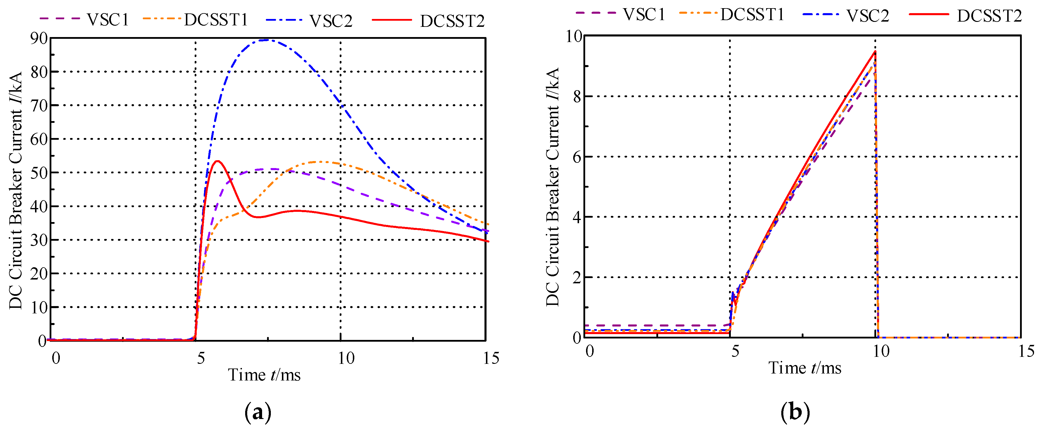
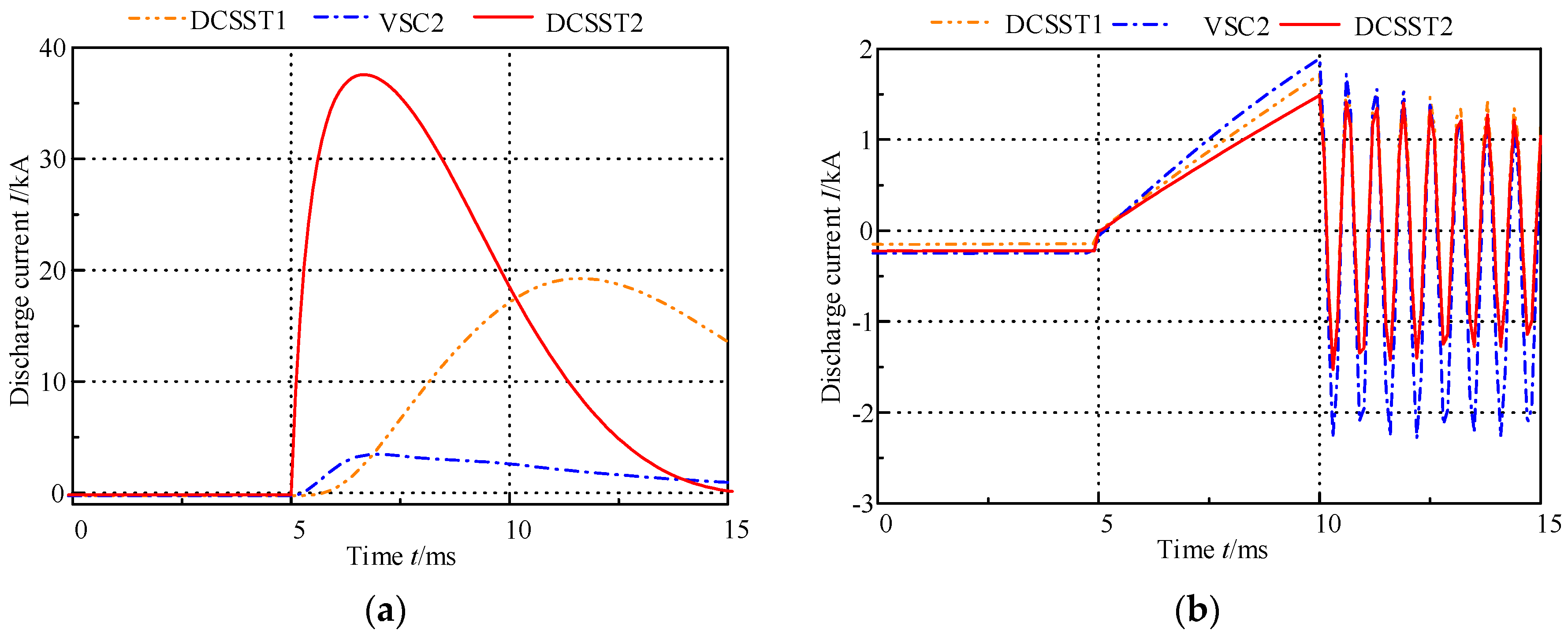
3.2. F2 Pole-To-Pole Fault

When the F2 fault occurs in the line side of the plug-in device, the fault current through the DC circuit breaker is the sum of discharge currents from the other devices, that is ifault = iC1 + iC2 + iC3 + iC4 + iC5, as shown in Figure 11. Therefore, in order to reach the breaking capacity of the DC circuit breaker, the fault current ifault needs to satisfy ifaultIDCB (ttDCB).
The capacitor discharge currents of VSC and DCSST under F2 fault are shown in (9) and (10).
i F 2 ( VSC ) = e δ t U dc ( VSC ) ω ( L ( VSC ) + L Cable ) sin ( ω t ) I L ( VSC ) e t ( L ( VSC ) + L Cable + L q ) / R Lstray ( VSC )
where ω = 1 ( L ( VSC ) + L Cable ) C ( VSC ) ( R Cstray ( VSC ) 2 ( L ( VSC ) + L Cable ) ) 2 , δ = R Cstray ( VSC ) 2 ( L ( VSC ) + L Cable ) , R Cstray ( VSC ) = R C + R L + R Breaker + R fault + R Cable , R Lstray ( VSC ) = R C + R L + R Breaker + R fault + R Cable .
i F 2 ( DCSST ) = e δ t [ U dc ( DCSST ) ω ( L ( DCSST ) + L Cable ) sin ( ω t ) ω 0 I L ( DCSST ) ω sin ( ω t β ) ]
where ω = 1 ( L ( DCSST ) + L Cable ) C ( DCSST ) ( R stray ( DCSST ) 2 ( L ( DCSST ) + L Cable ) ) 2 , δ = R stray ( DCSST ) 2 ( L ( DCSST ) + L Cable ) , ω 0 = 1 ( L ( DCSST ) + L Cable ) C ( DCSST ) , β = arctan ( ω δ ) , R stray ( DCSST ) = R C + R L + R Breaker + R fault + R Cable .
From the analysis above, it can be seen that the fault current through the DC circuit breaker is related to the line parameters, the number of devices, the capacitors of devices, and the value of current limiting reactors of each device. The fault current through the DC circuit breaker will be higher when the line is shorter, the number of plug-in devices is more, the current limiting reactors value are lower, and the capacitors of devices are larger.
In the initial stage of system design, in order to reduce the fault current, a longer line and a lesser number of the system devices should be considered if possible. Figure 12 gives an example of reducing the fault current as low as possible. It shows that the DC load and DC micro-grid are connected to the DC cable by the DC/DC transformer and the DC bus, while the AC voltage (including the AC Load and AC micro-grid) was converted to DC by the VSC converter.
In order to ensure that the fault current of the DC circuit breaker is under its breaking capacity in F2 fault, the fault current generated by each device should be limited to 1 N 1 I DCB ( t t DCB ) (where N is the total number of devices), and the fault current in the DC circuit breaker is given by
i fault = i C 1 + i C 2 + + i C N 1 1 N 1 I DCB + 1 N 1 I DCB + + 1 N 1 I DCB = I DCB ( t         t DCB )
Therefore, when the F2 fault occurs at the line side of VSC, the fault current iF2(vsc) should satisfy (12) after installing the current limiting reactor LF2(VSC).
i F 2 ( VSC ) 1 N 1 I DCB ( t t DCB )
For DCSST, the fault current iF2(DCSST) should satisfy (13) after installing the current limiting reactor LF2(DCSST).
i F 2 ( DCSST ) 1 N 1 I DCB ( t t DCB )

3.3. Design Method of Current Limiting Reactor Value
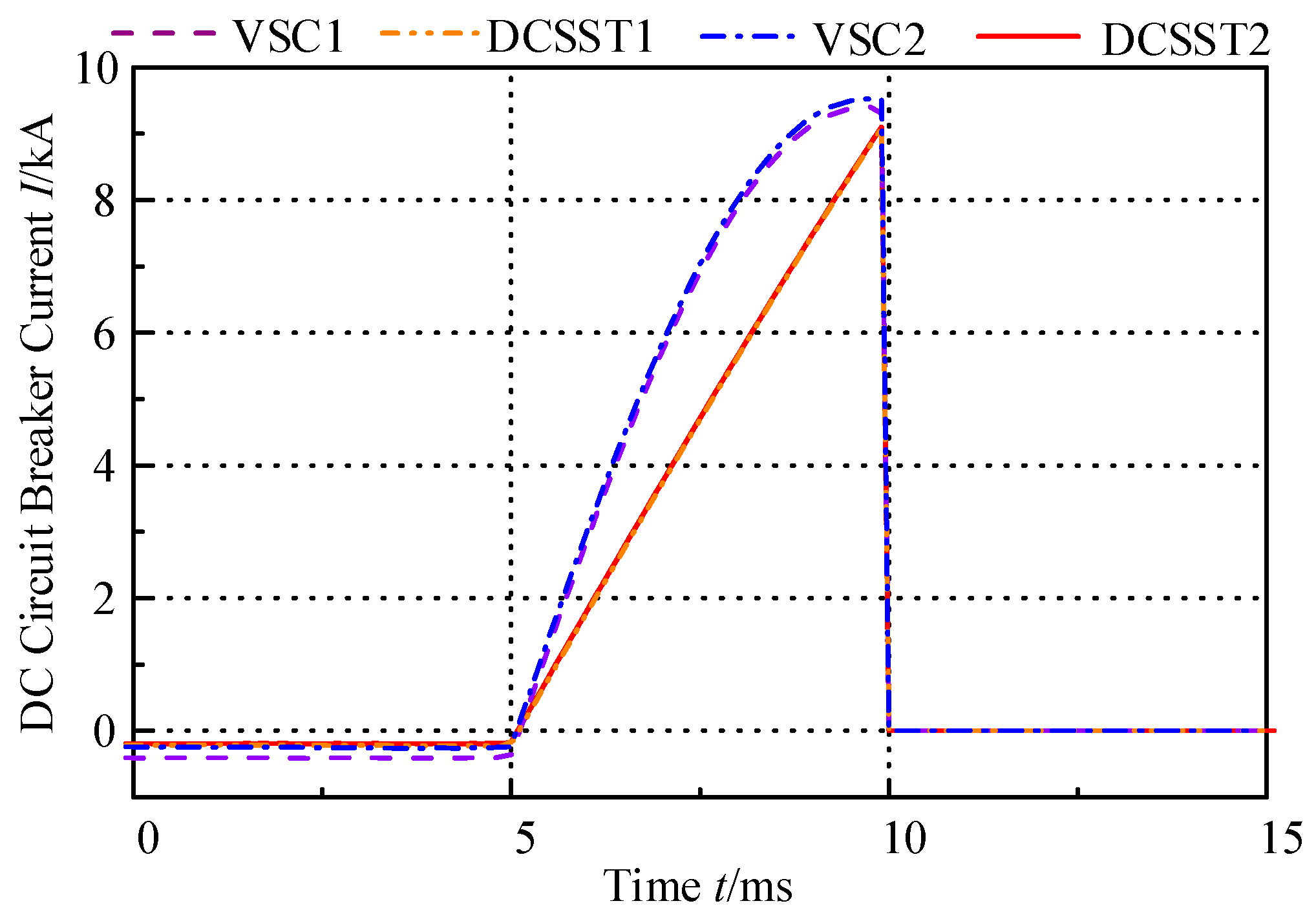
Considering F1 and F2 faults at the same time, the current limiting reactor value should be the higher value between (4) and (12), and is given by
L ( VSC ) = max [ L F 1 ( VSC ) , L F 2 ( VSC ) ]
For DCSST, the current limiting reactor value is the higher value between (8) and (13), and is given by
L ( DCSST ) = max [ L F 1 ( DCSST ) , L F 2 ( DCSST ) ]
However, due to the large fault current through DC circuit breaker under the F2 fault, a larger current limiting reactor is needed, which will lead to a larger size of equipment, larger overvoltage, and reduce the dynamic response of the system. It will increase the insulation level of the converter and the recovery time from fault to stability of the system. Compared with the F2 fault, only considering the F1 fault can reduce the value of current limiting reactor and improve the dynamic response, but the F2 fault should be avoided.

4. Simulation

In order to verify the theoretical analysis of the pole-to-pole fault characteristics and the design method of current limiting reactor value for plug-in devices, the simulation was carried out in PSCAD/EMTDC.

4.1. Simulation Modeling

A simulation model of the ±10 kV VSC-DC distribution system in Figure 1 is established in PSCAD/EMTDC. The converter stations, plug-in devices, loads, and line parameters are shown in Table 1, Table 2 and Table 3, respectively. The converter station is modeled by Thevenin equivalent model, the converter station I is in constant voltage control, and the converter station II is in constant power control. The DC circuit breaker is modeled by time-controlled switch, and the DC cable is modeled by frequency dependent model. The AC load and AC micro-grid are modeled by an equivalent three-phase load of corresponding power, and the DC load and the DC micro-grid are equivalently modeled by the DC current source of the corresponding power. In this simulation model, the time step size of simulation is 5 μs.

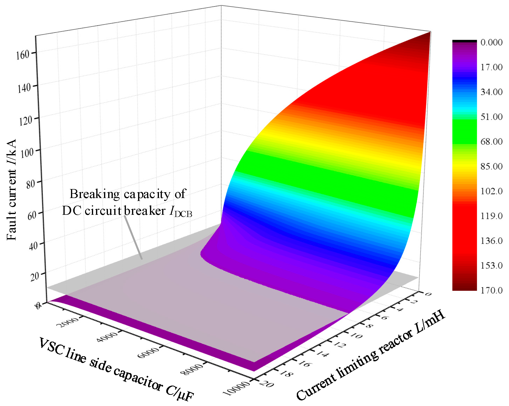
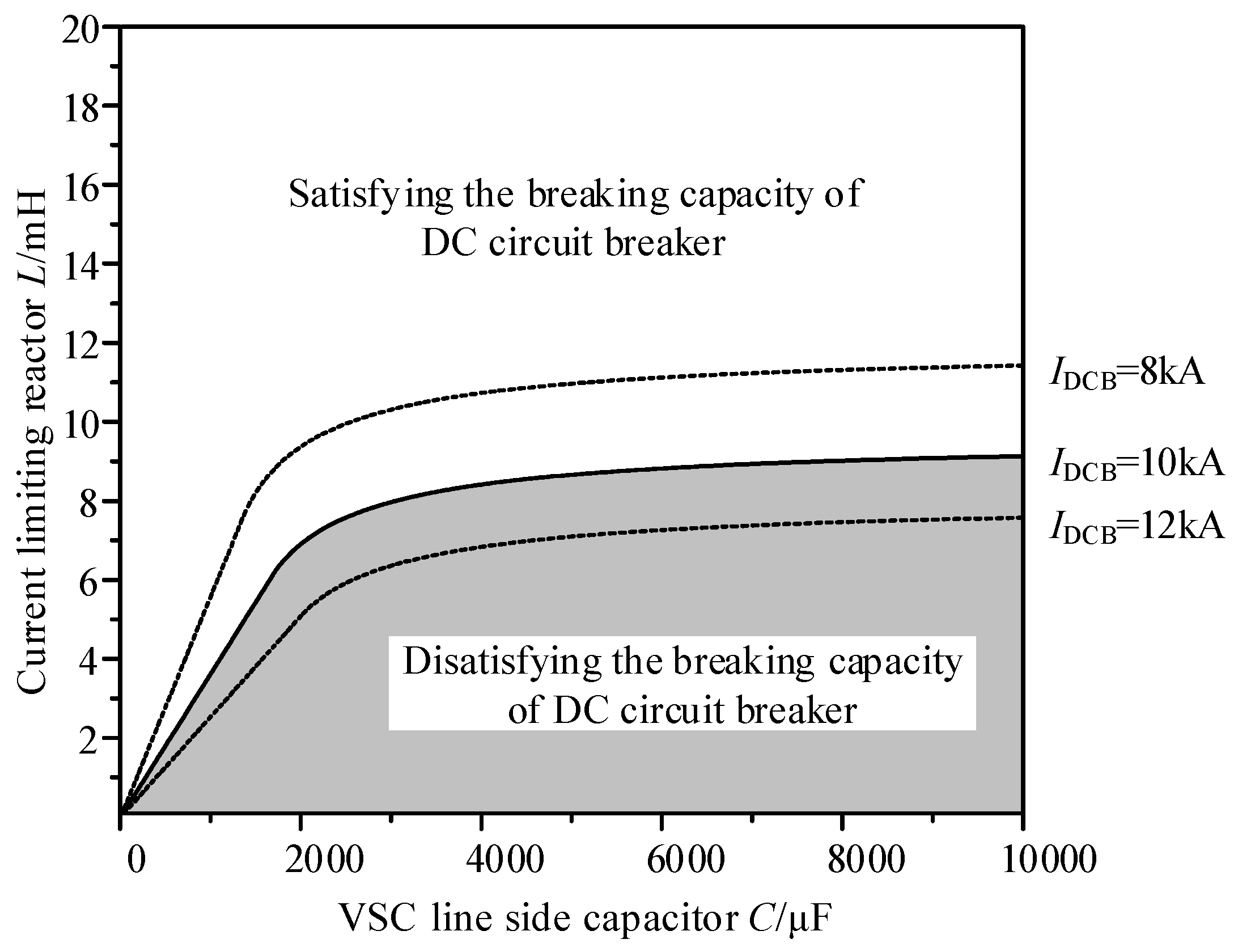
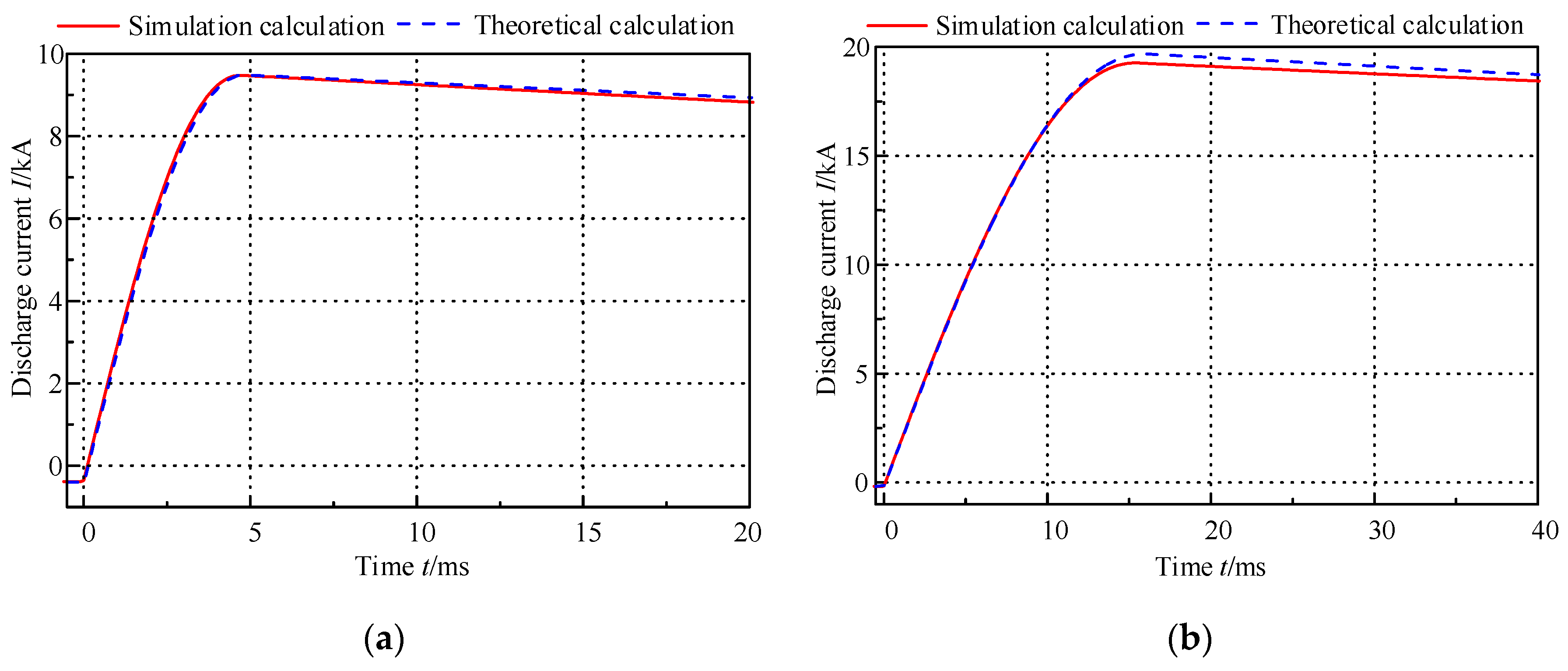
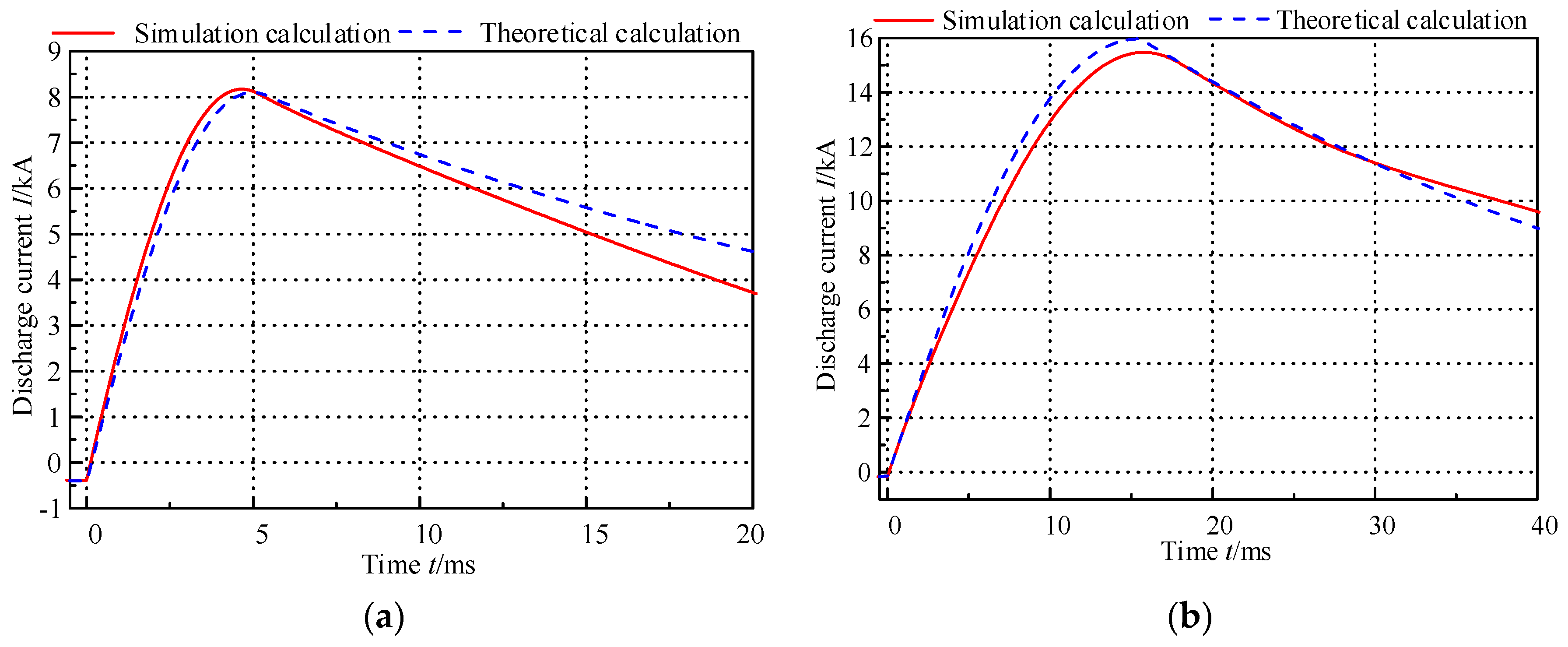
4.2. Theoretical Selection and Simulation Verification of Current Limiting Reactors

The DC circuit breaker used in this system can break 10 kA fault current within 5 milliseconds. Therefore, the value of the VSC and DCSST current limiting reactors can be obtained by (14) and (15), respectively. The theoretical results are shown in Table 4 by numerical method in Matlab.
That is, the current limiting reactors of 19 mH, 26.5 mH, 20.5 mH, and 28 mH should be installed at each pole of the VSC1, DCSST1, VSC2, and DCSST2 to cooperate with the DC circuit breakers. Compared with F1 faults, more devices discharge through short-circuit points under the F2 fault, resulting in higher fault current flowing through DC circuit breakers. As a result, larger current limiting reactors are needed. In addition, DCSST needs a larger current limiting reactor because of its larger capacitor.
In order to verify the feasibility of the calculation methods of the current limiting reactor, the accuracy of the calculation methods of the fault current should be verified at first. Take VSC1 and DCSST1 as examples, when the F1 fault occurs, the discharge current of VSC1 and DCSST1 are shown in Figure 13.
Figure 13 shows that the current waveform by theoretical calculation is consistent with the simulation calculation. Therefore, the accuracy of fault current calculation methods under F1 fault can be proved, and the feasibility of the calculation methods of the current limiting reactor value under F1 fault can be obtained.
For F2 fault, the discharge current of VSC1 and DCSST1 are shown in Figure 14.
When F2 fault occurs, the capacitor of the converters in the system will discharge to the fault point, but due to the difference of discharge time, different devices will charge and discharge each other. However, in order to limit the fault current, it is necessary to limit the fault current in the capacitor discharge stage. Figure 14 shows that in the capacitor discharge stage and the fault current rising stage, the theoretical calculation results are similar to the simulation. Therefore, according to the Equations (9) and (10), the fault current in the capacitor discharge stage under the F2 fault can be calculated, and then the calculation methods of the current limiting reactor value can be obtained.
In addition, in order to verify the current limiting effect of the current limiting reactors by theoretical calculation, the simulation of the F2 fault without current limiting reactors and with current limiting reactors is carried out, and the current waveform obtained by the simulation is shown in Figure 15. The discharge current waveform of DCSST1, VSC2, and DCSST2 during F2 fault in the line side of VSC1 are shown in Figure 16.
Figure 15 and Figure 16 show that the fault current will exceed the breaking capacity of the DC circuit breaker under F2 fault without installing the current limiting reactors, so that the DC circuit breaker cannot isolate the fault. In addition, the closer the device is to the fault point, the higher the discharge current is. After installing the current limiting reactors, the peak value of the fault current in 5 milliseconds is less than 10 kA, which satisfies the breaking capacity of DC circuit breakers. In addition, the discharge current of each plug-in device is less than 2 kA. Therefore, the value of current limiting reactor calculated Formulas (14) and (15) are effective.
However, if F2 fault is considered, the current limiting reactor will be very large, and this is almost impossible to be achieved in an actual project. Compared with the F2 fault, the F1 fault is located at the DC cable termination, so the probability of F1 fault occurrence is higher. If only F1 fault is considered, the value of current limiting reactor can be greatly reduced. The current waveform under F1 fault is shown in Figure 17.
Figure 17 shows that after installing the current limiting reactors, the peak value of the fault current in 5 milliseconds is less than 10 kA, which satisfies the breaking capacity of DC circuit breakers. Taking VSC1 as an example, if F2 fault is not considered, the value of limiting current reactor can be reduced by 84.2%. It can not only reduce the area and cost of equipment but can also reduce the overvoltage generated by the limiting current reactor and improve the dynamic response.

5. Conclusions

According to a ±10 kV VSC-DC distribution system, the paper studies the generation mechanism, influencing factors and limiting methods of the pole-to-pole fault current at the line side of plug-in devices. The main conclusions are as follows:
(a)
The generation mechanism of F1, F2 and F3 fault current are analyzed theoretically, in which F1 and F2 need to be taken into consideration when designing the current limiting reactors.
(b)
The generation mechanism and influencing factors of typical fault current in VSC and DCSST are analyzed theoretically, and the calculation methods of fault current are proposed, such as (1), (2), (5), (6), (9), (10). Also, the current magnitude at different time can be obtained by these calculation methods, so it can provide reference for the setting value of overcurrent protection.
(c)
Based on the generation mechanism of fault current and the breaking capacity of the DC circuit breaker, the calculation and selected methods of current limiter reactor value are proposed, such as (4), (8), (12), (13), (14), (15). The size of the current limiting reactor can be determined according to different system parameters and different breaking capacity of the DC circuit breaker. For different breaking capacities of DC circuit breakers, the corresponding current limiting reactor can be obtained by these calculation methods.
(d)
The accuracy and reliability of theoretical calculation methods are verified by simulation in PSCAD/EMTDC.

Author Contributions

Conceptualization, Y.H. and Y.G.; Methodology, Y.H. and Y.G.; Software, Y.G.; Validation, J.Z.; Formal analysis, F.X.; Investigation, F.X.; Resources, Y.G.; Data curation, J.Z.; Writing—original draft preparation, Y.G.; Writing—review and editing, Y.H.; Visualization, F.X.; Supervision, Y.H. and L.L.; Project administration, Y.H. and Y.Z.; Funding acquisition, Y.H. and Y.Z.

Funding

This research and APC were funded by [National Natural Science Foundation of China], grant number [51807068] and [National High Technology Research and Development (863) Program of China], grant number [2013AA050104].

Conflicts of Interest

The authors declare no conflict of interest.

References

  1. Zhao, B.; Zhao, Y.; Wang, Y.; Liu, G.; Song, Q.; Yuan, Z.; Yao, S. Energy Internet Based on Flexible Medium-voltage DC Distribution. Proc. CSEE 2015, 35, 4843–4851. [Google Scholar]
  2. Huang, A.Q.; Crow, M.L.; Heydt, G.T.; Zheng, J.P.; Dale, S.J. The Future Renewable Electric Energy Delivery and Management (FREEDM) System: The Energy Internet. Proc. IEEE 2011, 99, 133–148. [Google Scholar] [CrossRef]
  3. Has the Spring of VSC-DC Distribution System Come Yet? Available online: http://shupeidian.bjx.com.cn/html/20190103/953912.shtml (accessed on 1 March 2019).
  4. Wang, Y.; Yuan, Z.; Wen, W.; Ji, Y.; Fu, J.; Li, Y.; Zhao, Y. Generalised protection strategy for HB-MMC MTDC systems with RL-FCL under DC faults. IET Gener. Transm. Distrib. 2018, 12, 1231–1239. [Google Scholar] [CrossRef]
  5. Raza, A.; Akhtar, A.; Jamil, M.; Abbas, G.; Gilani, S.O.; Liu, Y.; Khan, M.N.; Izhar, T.; Xu, D.; Williams, B.W. A Protection Scheme for Multi-Terminal VSC-HVDC Transmission Systems. IEEE Access 2017, 6, 3159–3166. [Google Scholar] [CrossRef]
  6. Hӓfner, J.; Jacobson, B. Proactive Hybrid HVDC Breakers—A key innovation for reliable HVDC grids. In Proceedings of the Electric Power System of the Future Integrating Super Grids and Micro-grids International Symposium, Bologna, Italy, 13–15 September 2011. [Google Scholar]
  7. Huang, R.; Zhu, Z.; Chen, J.; Chen, M.; Zou, C.; Xu, S. Research and experimental validation of control and protection strategy of HVDC circuit breaker in fault condition application in Nan’ao multi-terminal VSC-HVDC system. Power Syst. Technol. 2018, 42, 2339–2345. [Google Scholar]
  8. Zhang, Z.; Li, X.; Chen, M.; Huang, Y.; Xu, S.; Zhao, X. Research on critical technical parameters of HVDC circuit breakers applied in Nan’ao multi-terminal VSC-HVDC project. Power Syst. Technol. 2017, 41, 2417–2422. [Google Scholar]
  9. Chen, Z.; Yu, Z.; Zhang, X.; Wei, T.; Lyu, G.; Qu, L.; Huang, Y.; Zeng, R. Analysis and Experiments for IGBT, IEGT, and IGCT in Hybrid DC Circuit Breaker. IEEE Trans. Ind. Electron. 2018, 65, 2883–2892. [Google Scholar] [CrossRef]
  10. Lyu, G.; Yu, Z.; Zeng, R.; Liu, J.; Zhang, X.; Long, T.; Palmer, P. Optimisation of gate-commutated thyristors for hybrid DC breakers. IET Power Electron. 2017, 10, 2002–2009. [Google Scholar] [CrossRef]
  11. Wen, W.; Huang, Y.; Cheng, T.; Gao, S.; Chen, Z.; Zhang, X.; Yu, Z.; Zeng, R.; Liu, W. Research on a current commutation drive circuit for hybrid dc circuit breaker and its optimisation design. IET Gener. Transm. Distrib. 2016, 10, 3119–3126. [Google Scholar] [CrossRef]
  12. Zhu, T.; Yu, Z.; Zeng, R.; Lü, G.; Chen, Z.; Zhang, X.; Zhao, Y.; Chen, M.; Huang, Y.; Wen, W. Transient Model and Operation Characteristics Researches of Hybrid DC Circuit Breaker. Proc. CSEE 2016, 36, 18–30. [Google Scholar]
  13. Chen, M.; Zhao, Y.; Li, X.; Xu, S.; Sun, W.; Zhu, T.; Zeng, R.; Chen, Z.; Yu, Z. Development of topology and power electronic devices for solid-state circuit breakers. In Proceedings of the 2nd International Symposium on Instrumentation and Measurement, Sensor Network and Automation (IMSNA), Toronto, ON, Canada, 23–24 December 2013. [Google Scholar]
  14. Liu, J.; Ta, N.; Fan, C.; Shi, C. A Hybrid Current-limiting Circuit for DC Line Fault in Multi-terminal VSC-HVDC System. IEEE Trans. Ind. Electron. 2017, 64, 5595–5607. [Google Scholar] [CrossRef]
  15. Guo, Z.; Han, Y.; Zhao, Y.; He, Q.; Liu, G.; Li, L. Study on Transient Current of the Key Equipment in Flexible DC Power Distribution System. High Volt. Eng. 2017, 43, 1280–1288. [Google Scholar]
  16. Morishita, Y.; Ishikawa, T.; Yamaguchi, I.; Okabe, S.; Ueta, G.; Yanabu, S. Applications of DC Breakers and Concepts for Superconducting Fault-Current Limiter for a DC Distribution Network. IEEE Trans. Appl. Supercond. 2009, 19, 3658–3664. [Google Scholar] [CrossRef]
  17. Xie, S.; Qiu, Y.; Bi, T. Resistive DC fault current limiter. J. Eng. 2017, 2017, 1682–1685. [Google Scholar]
  18. Xu, K.; Wang, T.; Zhu, Y.; Xia, R. Fault Current Limiting Strategy for Flexible Power Distribution System Based on Voltage Source Converters. Autom. Electr. Power Syst. 2017, 41, 118–123. [Google Scholar]
  19. Li, B.; He, J. Studies on the Application of R-SFCL in the VSC-Based DC Distribution System. IEEE Trans. Appl. Supercond. 2016, 26, 5601005. [Google Scholar] [CrossRef]
  20. Li, B.; He, J. DC Fault Analysis and Current Limiting Technique for VSC-based DC Distribution System. Proc. CSEE 2015, 35, 3026–3036. [Google Scholar]
  21. Callavik, M.; Blomberg, A.; Häfner, J.; Jacobson, B. Breakthrough! ABB’s hybrid HVDC breaker, an innovation breakthrough enabling reliable HVDC grids. ABB Rev. 2013, 2, 7–13. [Google Scholar]
  22. Steven, D.A.F.; Patrick, J.N.; Kenny, F.; Stuart, J.G.; Graeme, M.B. High-Speed Differential Protection for Smart DC Distribution Systems. IEEE Trans. Smart Grid 2014, 5, 2610–2617. [Google Scholar] [Green Version]
  23. Li, B.; He, J.; Li, Y.; Ou, Y. Single-ended Protection Scheme Based on Boundary Characteristic for the Multi-terminal VSC-based DC Distribution System. Proc. CSEE 2016, 36, 5741–5749. [Google Scholar]
  24. Wang, Y.; Yuan, Z.; Fu, J.; Li, Y.; Zhao, Y. A feasible coordination protection strategy for MMC-MTDC systems under DC faults. Int. J. Electr. Power Energy Syst. 2017, 90, 103–111. [Google Scholar] [CrossRef]
  25. Luo, Y.; He, J.; Luo, G.; Zhang, Y. Fast DC fault location and isolation strategy for the flexible multi-terminal DC system. J. Eng. 2018, 2018, 908–912. [Google Scholar] [CrossRef]
  26. Li, C.; Zhao, C.; Xu, J.; Ji, Y.; Zhang, F.; An, T. A Pole-to-Pole Short-Circuit Fault Current Calculation Method for DC Grids. IEEE Trans. Power Syst. 2017, 32, 4943–4953. [Google Scholar] [CrossRef]
  27. Li, B.; He, J.; Jie, T.; Feng, Y.; Dong, Y. DC fault analysis for modular multilevel converter-based system. J. Mod. Power Syst. Clean Energy 2017, 5, 275–282. [Google Scholar] [CrossRef]
  28. Shuai, Z.; He, D.; Xiong, Z.; Lei, Z.; Shen, Z.J. Comparative Study of Short-Circuit Fault Characteristics for VSC-Based DC Distribution Networks with Different Distributed Generators. IEEE J. Emerg. Sel. Topics Power Electron. 2019, 7, 528–540. [Google Scholar] [CrossRef]
  29. Ji, Y.; Yuan, Z.; Zhao, J.; Lu, C.; Wang, Y.; Zhao, Y.; Li, Y.; Han, Y. Hierarchical control strategy for MVDC distribution network under large disturbance. IET Generat. Transm. Distrib. 2018, 12, 2557–2565. [Google Scholar] [CrossRef]
  30. Jian, S.; Fan, C.; Ning, N.; Zeng, J. Fault Characteristic Analysis of DC Pole-to-Pole Fault in Power Electronic Transformer. Proc. CSEE 2018, 38, 1301–1309. [Google Scholar]
  31. Liu, G.; Zhao, B.; Zhao, Y.; Wang, Y.; Song, Q.; Yuan, Z.; Yao, S. Application Framework of VSC Medium-voltage DC Distribution Technology in Shenzhen Power Grid. South. Power Syst. Technol. 2015, 9, 1–10. [Google Scholar]
  32. Liu, G.; Zhao, Y.; Yuan, Z.; Zhao, B.; Yu, Z.; Si, Z.; Sun, G.; Xu, X.; Han, Y.; He, Q.; et al. Study on Demonstration Project Technical Scheme of VSC-DC Distribution System in Shenzhen. South. Power Syst. Technol. 2016, 10, 1–7. [Google Scholar]
  33. Wang, Y.; Song, Q.; Sun, Q.; Zhao, B.; Li, J.; Liu, W. Multilevel MVDC Link Strategy of High-Frequency-Link DC Transformer Based on Switched Capacitor for MVDC Power Distribution. IEEE Trans. Ind. Electron. 2017, 64, 2829–2835. [Google Scholar] [CrossRef]
  34. Zhao, B.; Song, Q.; Liu, W.; Zhao, Y. Transient DC Bias and Current Impact Effects of High-Frequency-Isolated Bidirectional DC–DC Converter in Practice. IEEE Trans. Power Electron. 2016, 31, 3203–3216. [Google Scholar] [CrossRef]
Figure 1. Topological structure of the ±10 kV VSC-DC distribution system.
Energies 12 03159 g001
Figure 2. The possible pole-to-pole faults at the line side of plug-in devices.
Energies 12 03159 g002
Figure 3. The first stage discharge circuit of VSC fault.
Energies 12 03159 g003
Figure 4. Equivalent circuit of the first stage discharge circuit of VSC: (a) capacitor and inductor discharge equivalent circuit and (b) inductor discharge equivalent circuit.
Energies 12 03159 g004
Figure 5. The second stage discharge circuit of VSC fault.
Energies 12 03159 g005
Figure 6. Equivalent circuit of the second stage discharge circuit of VSC.
Energies 12 03159 g006
Figure 7. Effect of VSC line side capacitor and current limiting reactor (C, L(VSC)) on the fault current of DC circuit breaker.
Energies 12 03159 g007
Figure 8. Relationship between DC circuit breaker breaking capacity IDCB and VSC capacitor C, current limiting reactor L(VSC).
Energies 12 03159 g008
Figure 9. The first stage discharge circuit of DCSST fault.
Energies 12 03159 g009
Figure 10. Equivalent circuit of the first stage discharge circuit of DCSST.
Energies 12 03159 g010
Figure 11. When F2 pole-to-pole fault occurs in plug-in device 2, other devices discharge to the fault point.
Energies 12 03159 g011
Figure 12. Topological structure of VSC-DC distribution system.
Energies 12 03159 g012
Figure 13. The current waveform under F1 fault by theoretical calculation and simulation calculation: (a) VSC1 discharge current and (b) DCSST1 discharge current.
Energies 12 03159 g013
Figure 14. The current waveform under F2 fault by theoretical calculation and simulation calculation: (a) VSC1 discharge current when F2 fault occurs in DCSST1 and (b) DCSST1 discharge current when F2 fault occurs in VSC1.
Energies 12 03159 g014
Figure 15. The current of the DC circuit breakers in each device under F2 fault: (a) without current limiting reactors and (b) with current limiting reactors.
Energies 12 03159 g015
Figure 16. The current of DCSST1, VSC2, and DCSST2 under F2 fault in VSC1: (a) without current limiting reactors and (b) with current limiting reactors.
Energies 12 03159 g016
Figure 17. The current of the DC circuit breakers in each device under F1 fault.
Energies 12 03159 g017
Table 1. Parameters of Main Converters.
DeviceConverter station IConverter station II
Capacity25 MW25 MW
Submodule number2525
Bridge arm reactor2.5 mH2.5 mH
Submodule capacitor31,178 μF31,178 μF
Table 2. Parameters of Plug-In Devices and Loads.
DeviceVSC1DCSST1VSC2DCSST2
Load side voltage10 kVac400 Vdc380 Vac400 Vdc
Line side capacitor1500 μF10,000 μF1500 μF10,000 μF
Load typeAC loadDC loadAC micro-gridDC micro-grid
Capacity8 MW4 MW5 MW2.5 MW
Table 3. Parameters of DC Cable.
NumberLength/kmInductance/mHResistance/Ω
12.31.09740.106
20.90.42940.0415
30.90.42940.0415
40.90.42940.0415
51.00.47710.0461
Table 4. Theoretical Calculation Results of Current Limiting Reactor for Per Pole.
DeviceLF1/mHLF2/mHL = max[LF1, LF2]/mH
VSC131919
DCSST1526.526.5
VSC2326.526.5
DCSST252828

