1. Introduction
Generally, the air gap flux controlling in a permanent magnet machine can be realized in two ways: By the appropriate control system or by the relevant changes of the machine design. Conventional permanent magnet (PM) machines have a constant, non-adjustable excitation flux, which limits the power, thus becoming an important limitation. In the case of U/f = const. control strategy implementation, due to the limited power of the supply voltage and limited dielectric strength of winding insulation, to achieve higher speeds it is required to weaken the excitation flux, in order to reduce the back-EMF value. A very popular method of field weakening is realized by adjusting the current in the d-axis of the machine. This strategy, however, generates increased losses in the supply system and creates the risk of permanent magnets demagnetization, and consequently decreases the resultant torque of the machine.
Conventional permanent magnet excited synchronous machines (PMSM), used as a drive in modern electric vehicles, suffer from the limited battery voltage in high-speed regions because of high back-EMF values. The field weakening (which is obligatory) requires design of machines with lower power conversion characteristics. This caused the development of hybrid excited synchronous machines [
1,
2,
3,
4,
5,
6,
7,
8,
9,
10,
11,
12,
13,
14,
15,
16]. These machines have PM excitation and an additional toroidal excitation coil fixed on the stator or mounted in the rotor in the machine axial center. By the proper powering of this coil, the amplitude of the induced voltage can be effectively controlled in the range from zero to values above those of classical permanent magnet machines. The hybrid excited synchronous machines have already been designed, optimized and measured very intensively [
6,
7,
8,
9].
For the reason mentioned above, in this paper an unconventional approach to control the hybrid excited synchronous machine (HESM), which can be used for the drives of electric vehicles, has been proposed. This solution consists of the hybrid excitation, which is characterized by the fact that the additional control coil is placed on the machine rotor and the power supply is implemented using the wireless energy transfer system connected with the rotor shaft.
2. Review of PM Machines with Adjustable Flux Excitation
To realize the controlling of the excitation field (back-EMF) of the machine with PMs, different methods that require structural changes have been used. Regarding to reluctance machines the construction with two parts of salient permanent magnets (double salient permanent magnet—DSPM) was proposed. DSPM machines are realized with internal (
Figure 1) and external rotor structures [
10,
11], wherein the solution of the outer rotor, as shown in
Figure 2, has no additional control coil. The advantage of these machines is a lower production cost caused by small amounts of permanent magnets.
The other design of cylindrical machines with permanent magnets is one with a movable rotor, which—at higher speeds—moves in the axial direction, leaving its part outside of the stator [
12]. Such a solution leads very effectively to the reduction of back-EMF, but its disadvantage is a complicated structure and the lack of possibility to increase the excitation flux, useful at low speed operation range.
In the literature can also be found designs with a double rotor. In this solution there is one shaft, which is common to two different rotor topologies: A conventional PM rotor and laminated reluctance rotor without magnets. This conception allows to obtain a machine which has a high ratio of inductances
Ld/
Lq [
13].
Many designs are described in paper [
14], where the authors present solutions of hybrid excited machines for both cylindrical and disk-type machines. Similar characteristics can be obtained with suitably located magnetic barriers [
15]. In the literature are also known designs of claw pole [
16,
17] (
Figure 3) and disc-type machines with adjustable excitation flux [
18].
Hybrid excited Vernier machines are a large group of machines with adjustable excitation flux. In a previous paper [
19], structures with magnets mounted on the surface and using magnetic concentrators were presented. Whereas, [
20] presents a Vernier permanent magnet machine that uses homopolar topology. The authors of [
21] presented research of the machine, whose rotor consists of two parts: One has permanent magnets, and the other electromagnets analogous to that of the wound field synchronous machines.
Another solution is presented in [
22]. The paper shows simulation and experimental research of hybrid excited flux-switching PM machines with iron flux bridges. Research on a similar construction is in [
23]. Furthermore, in [
24] an influence of stator and rotor pole combinations on machine parameters were theoretically and experimentally tested.
A very wide review of hybrid-excited machines together with theoretical and experimental research was presented in [
25]. The authors searched for the optimal construction of an electric machine for use in an electric vehicle.
3. Hybrid Excited Synchronous Machine Design
Control systems of hybrid excited synchronous machines differ from those of conventional permanent magnet excited synchronous machines (PMSM). They have the ability to adjust the excitation flux by using an additional control coil [
6,
7,
8]. This feature gives the possibility of the dynamic flux control that provides an additional degree of freedom of the machine control. The hybrid excitation source increases the efficiency of the drive system in a wide range of load torques and speeds. All advantages of using the hybrid excitation can be obtained by the proper design, both of the machine and the control system.
In previous designs of hybrid-excited synchronous machines the additional excitation coil was placed on the stator. In this paper, a new design of the coil location on the machine rotor is presented. Usually, in order to supply the windings placed on the rotor, it is necessary to use brushes and slip rings. Alternatively to this, contactless energy transfer (CET) systems can be used [
8].
Figure 4 shows construction details of the hybrid excited synchronous machine and in
Table 1 the main data are listed. Supply coils used for the wireless power transfer have been designed and initially optimized. They are connected with the housing of the hybrid excited synchronous machine.
4. FEA Results of Field Control Predictions of HESM
In order to predict the field control (FC) characteristics, three dimensional finite element analysis (3D-FEA) studies have been carried out under no-load armature windings conditions.
Figure 5 shows the magnetic flux distribution within a 3D-FEA model of an HES machine obtained at no-load of the rotor DC control coil. To analyze a field control range (FCR) factor, as a ratio of a field strengthening (FS) operation gained by positive value of the rotor DC control coil current (
IDC), to a field weakening (FW) operation obtained at negative value of
IDC, three different magnetomotive forces of the rotor DC control coil in the range from −1000 to 1000 Ampere-turns, it means at
IDC = 0 and
IDC = ±1.0 A have been analyzed. The resistance of the rotor DC control coil is 19 Ω and the inductance is about 400 mH.
Figure 6 shows the phase back-EMF waveforms simulated at the rotor constant speed of 1000 rpm by three operating conditions. These results show that FCR up to 4:1 can be effectively obtained with a small rotor DC control coil having power losses of max. 20 W.
5. Mathematical Model of HESM
Defining the adequate mathematical machine model is necessary to develop a control strategy in both steady state and in transient modes. This model is also indispensable to realize a new proposition of the machine power supply system control in a fault mode of operation, and also in the field weakening and strengthening ranges. This model has been developed under typical assumptions: armature windings are symmetric, windings inductance and resistance are constant, permanent magnets flux is also constant, and magnetic flux density higher harmonics are neglected. Finally, the
d- and
q-axis voltages and the electromagnetic torque of hybrid-excited machines can be written as:
where
p—number of pair poles;
Ψd,
Ψq—
d- and
q-axis magnetic fluxes;
Ψpm—flux generated by PMs;
Id,
Iq—
d- and
q-axis stator currents;
Ld,
Lq—
d- and
q-axis inductances;
MDC—mutual inductance of the additional coil;
IDC—current in the additional coil.
Equation (3) shows the possibility of forming a specified electromagnetic torque at different values of the individual components of the stator current (Id, Iq) and additional coil current IDC.
Due to the additional degree of freedom in the form of resultant flux control by the coil current, it is possible to generate a specific electromagnetic torque at different values of stator current components
Id and
Iq. If high torque is desired, it is preferred to increase the excitation flux of the machine, thus it is possible to reduce the stator current. In the high rotational speeds, due to the induced high voltage, the proper power supply of the machine requires the weakening of the excitation flux. Reducing the flux can also affect the reduction of losses in the machine magnetic circuit. Appropriately controlling the auxiliary winding of the hybrid machine can finally increase its efficiency [
7].
6. Supply and Control System of HESM
The power supply of the control coil on the rotor use the classical system of slip rings and brushes or a rotary transformer. Due to the reliability, quiet operation and low maintenance, the use of contactless energy transfer is best. Many design variants of this solution have already been analyzed in [
26,
27].
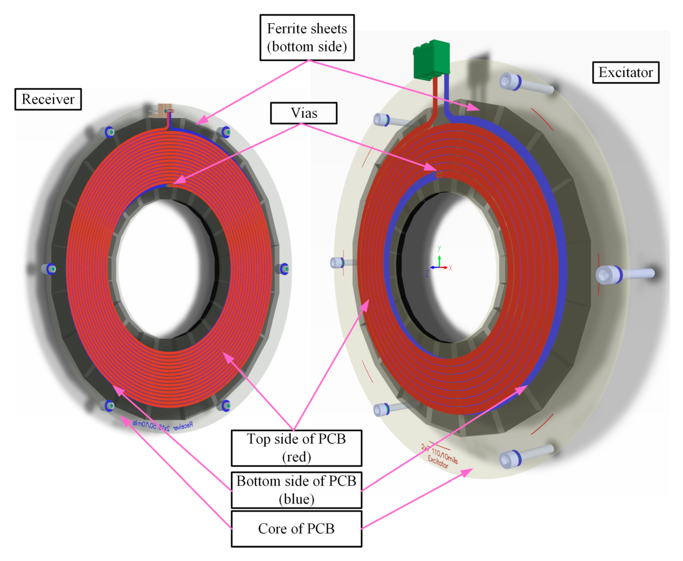
The analyzed machine uses a transformer whose winding is formed by a double-sided printed circuit board (PCB) with 70 µm copper thickness. This allowed the simplification of the structure and reduces the width. On both parts of the secondary and primary plates, ferrite sheets were used as the path of the magnetic flux (Wurth Electronic® WE-FSFS flexible ferrite sheet, number 344003) [
28]. Air gap between TX and RX-coil is about 1.2 mm. Constructional details are shown in
Figure 7 and PCBs coils are shown in
Figure 8. The control algorithm takes into account the mathematical model of the HESM (1)–(3).
In order to enable the change of direction of the coil current in the rotor, a DC/DC controller of
IDC and the control circuit were located on the secondary side of the rotary transformer (rotating part). The required values of the current are transmitted from the master control system by using radio transmitter and receiver (2.4 GHz integrated radio module). The transmitting coil is supplied with a voltage inverter having an operating frequency of 100 kHz. Wireless energy transfer to the secondary coil was investigated for series-series resonant operation using two resonant capacitors without additional compensation circuits [
29]. Operating frequency of coil’s current controller was 10 kHz. A block diagram of the control coils power system is shown in
Figure 9.
For the research, simulation models were made using the PLECS® software (
Figure 10) in order to examine properties of novel contactless energy transfer systems. In order to test the transient and averaged voltages and currents, time domain analyses have been conducted. These analyses were also led in order to examine the thermal stress of the semiconductor. This numerical model was divided into four subsystems:
7. Experimental Setup and Validation
To verify the presented control strategy and the FCR of the prototype, an experimental setup for the proposed HESM as a generator was established. It was mechanically connected to a high-speed induction machine (
Figure 11).
Secondly, the rotating part (rectifier, control system, radio receiver and IDC current controller) of the wireless energy transfer system was implemented as a flexible PCB (
Figure 12) fixed to a plastic support.
The main construction elements of the secondary supply system include IPD082N10N3 Mosfet power transistors for the IDC current controller and a IDD04SG60C SiC Schottky diode for the rectifier. As a control and central processing unit the TMS320F28027 (Piccolo family) by Texas Instruments has been used. The excitation system was a full bridge converter (Mosfets CSD88599Q5DC), also controlled by the TMS320F28027 processor.
In order to verify the basic properties of proposed wireless power transfer system configuration, the experimental test stand was built. Basic waveforms obtained from simulations and measurements (output voltage and current from excitation inverter) confirm correct resonant operation of the supply system (
Figure 13). Additionally, in
Figure 14, measured efficiency and power losses of the wireless rotor power supply system are shown.
In
Table 2 and
Figure 15 are depicted RMS values of back-EMF at 1000 rpm rotor speed for the three operating conditions obtained experimentally and during 3D-FEA analysis.
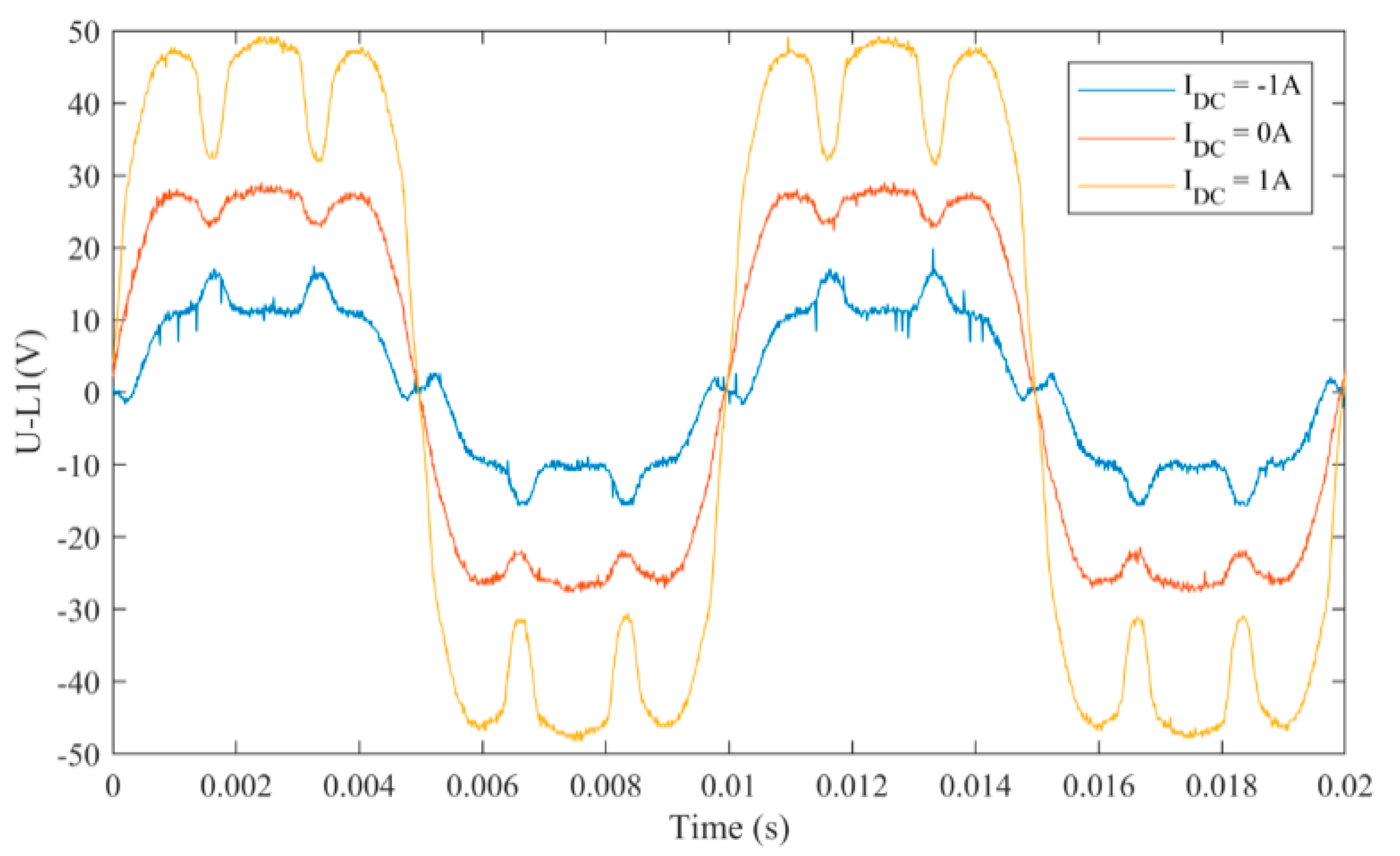
Waveforms of induced voltages at selected values of
IDC currents are shown in
Figure 16.
8. Conclusions
By controlling the auxiliary rotor coil current and the stator current, it is possible to use the specific features of hybrid machines in the whole range of resulting torques and speeds. Application of the rotary transformer complicates the supply system, however as shown by simulation studies, the value of power delivered to the additional coil placed on the rotor is big enough in order to influence the main flux of the machine. The paper also presents results of experimental tests that confirmed the efficiency of power supply and control of the excitation current using the novel wireless system. The further improvement of the efficiency of energy transfer requires additional optimization of the whole rotor coil supply system, which will be the subject of future research.
Author Contributions
All authors worked on this manuscript together and analyzed the obtained data. Conceptualization, R.P.; investigation, M.W., M.B., P.P. (Piotr Paplicki) and P.P. (Pawel Prajzendanc); methodology, R.P.; validation, M.W., M.B., P.P. (Piotr Paplicki) and P.P. (Pawel Prajzendanc); writing—original draft, M.W., M.B., P.P. (Piotr Paplicki) and P.P. (Pawel Prajzendanc); writing—review and editing, R.P. All authors revised and approved the final version of the paper.
Funding
This work has been supported with the grant of the National Science Centre, Poland 2018/02/X/ST8/01112.
Conflicts of Interest
The authors declare no conflict of interest.
References
- Jahns, T.M. Flux-weakening regime operation of an interior permanent-magnet synchronous motor drive. IEEE Trans. Ind. Appl. 1987, 23, 681–689. [Google Scholar] [CrossRef]
- Chau, K.; Chan, C.; Liu, C. Overview of permanent-magnet brushless drives for electric and hybrid electric vehicles. IEEE Trans. Ind. Electron. 2008, 55, 2246–2257. [Google Scholar] [CrossRef]
- Wang, Y.; Deng, Z. Hybrid Excitation Topologies and Control Strategies of Stator Permanent Magnet Machines for DC Power System. IEEE Trans. Ind. Electron. 2012, 59, 4601–4616. [Google Scholar] [CrossRef]
- Wang, Q.; Niu, S.; Luo, X. A Novel Hybrid Dual-PM Machine Excited by AC with DC Bias for Electric Vehicle Propulsion. IEEE Trans. Ind. Electron. 2017, 64, 6908–6919. [Google Scholar] [CrossRef]
- Hua, H.; Zhu, Z.Q.; Zhan, H. Novel Consequent-Pole Hybrid Excited Machine with Separated Excitation Stator. IEEE Trans. Ind. Electron. 2016, 63, 4718–4728. [Google Scholar] [CrossRef]
- Wardach, M.; Paplicki, P.; Palka, R. Hybrid Excited Machine with Flux Barriers and Magnetic Bridges. Energies 2018, 11, 676. [Google Scholar] [CrossRef]
- Di Barba, P.; Mognaschi, M.E.; Bonislawski, M.; Palka, R.; Paplicki, P.; Wardach, M. Hybrid excited synchronous machine with flux control possibility. Int. J. Appl. Electromagn. Mech. 2016, 52, 1615–1622. [Google Scholar] [CrossRef]
- Bonislawski, M.; Palka, R.; Paplicki, P.; Wardach, M. Unconventional control system of hybrid excited synchronous machine. In Proceedings of the 2015 20th International Conference on Methods and Models in Automation and Robotics (MMAR), Miedzyzdroje, Poland, 24–27 August 2015; pp. 649–654. [Google Scholar] [CrossRef]
- Palka, R. Synthesis of magnetic fields by optimization of the shape of areas and source distributions. Electr. Eng. 1991, 75, 1–7. [Google Scholar] [CrossRef]
- Shakal, A.; Liao, Y.; Lipo, T.A. A permanent magnet AC machine structure with true field weakening capability. In Proceedings of the IEEE International Symposium on Industrial Electronics Conference, Budapest, Hungary, 1–3 June 1993; pp. 19–24. [Google Scholar]
- Luo, J. Axial Flux Circumferential Current Permanent Magnet Electric Machine. Ph.D. Thesis, University of Wisconsin-Madison, Madison, WI, USA, 1999. [Google Scholar]
- Zepp, L.P.; Medlin, J.W. Brushless Permanent Magnet Motor or Alternator with Variable Axial Rotor/Stator Alignment to Increase Speed Capability. U.S. Patent 6555941 B1, 29 April 2003. [Google Scholar]
- Chalmers, B.J.; Akmese, R.; Musaba, L. Design and field weakening performance of permanent-magnet/reluctance motor with two-part rotor. IEE Proc. Electr. Power Appl. 1998, 145, 133–139. [Google Scholar] [CrossRef]
- Amara, Y.; Vido, L.; Gabsi, M.; Hoang, E.; Ben Ahmed, A.H.; Lecrivain, M. Hybrid excitation synchronous machines: Energy-efficient solution for vehicles propulsion. IEEE Trans. Veh. Technol. 2009, 58, 2137–2149. [Google Scholar] [CrossRef]
- Xu, L.; Ye, L.; Zhen, L.; El-Antably, A. A new design concept of, permanent magnet machine for flux weakening operation. IEEE Trans. Ind. Appl. 1995, 31, 373–378. [Google Scholar]
- Wardach, M. Hybrid excited claw pole electric machine. In Proceedings of the 21st International Conference on Methods and Models in Automation and Robotics (MMAR), Miedzyzdroje, Poland, 29 August–1 September 2016; pp. 152–156. [Google Scholar] [CrossRef]
- Wardach, M. The Influence of Permanent Magnet Amount on No-load Parameters of Hybrid Excited Claw Pole Machine with Laminated Rotor. In Proceedings of the Selected Issues of Electrical Engineering and Electronics (WZEE’2018), Szczecin, Poland, 19–21 November 2018. [Google Scholar]
- Aydin, M.; Huang, S.; Lipo, T.A. A new axial flux surface mounted permanent magnet machine capable of field control. In Proceedings of the 2002 IEEE Industry Applications Conference. 37th IAS Annual Meeting, Pittsburgh, PA, USA, 13–18 October 2002; pp. 1250–1257. [Google Scholar] [CrossRef]
- Xu, L.; Liu, G.; Zhao, W.; Ji, J. Hybrid Excited Vernier Machines with All Excitation Sources on the Stator for Electric Vehicles. Prog. Electromagn. Res. 2016, 46, 113–123. [Google Scholar] [CrossRef]
- Li, W.; Ching, T.W.; Chau, K.T. A Hybrid-Excited Vernier Permanent Magnet Machine Using Homopolar Topology. IEEE Trans. Magn. 2017, 53, 11. [Google Scholar] [CrossRef]
- Bernatt, J.; Gawron, S.A.; Glinka, M. Experimental Validation of Hybrid Excited Permanent Magnet Synchronous Generator. Prz. Elektrotechniczny (Electr. Rev.) 2012, 88, 66–70. [Google Scholar]
- Owen, R.L.; Zhu, Z.Q.; Jewell, G.W. Hybrid-Excited Flux-Switching Permanent-Magnet Machines with Iron Flux Bridges. IEEE Trans. Magn. 2010, 46, 1726–1729. [Google Scholar] [CrossRef]
- Dupas, A.; Hoang, E.; Hlioui, S.; Gaussens, B.; Lécrivain, M.; Gabsi, M. Performances of a hybrid excited flux-switching DC-alternator: Analysis and experiments. In Proceedings of the 2014 International Conference on Electrical Machines (ICEM), Berlin, Germany, 2–5 September 2014; pp. 2644–2649. [Google Scholar]
- Zhu, Z.Q.; Afinowi, I.A.A.; Guan, Y.; Mipo, J.C.; Farah, P. Hybrid-Excited Stator Slot Permanent Magnet Machines—Influence of Stator and Rotor Pole Combinations. IEEE Trans. Magn. 2016, 52, 1–10. [Google Scholar] [CrossRef]
- Asfirane, S.; Hlioui, S.; Amara, Y.; Gabsi, M. Study of a Hybrid Excitation Synchronous Machine: Modeling and Experimental Validation. Math. Comput. Appl. 2019, 24, 34. [Google Scholar] [CrossRef]
- Weber, J.N.; Rehfeldt, A.; Vip, S.A.; Ponick, B. Rotary transformer with electrical steel core for brushless excitation of synchronous machines. In Proceedings of the 2016 XXII International Conference on Electrical Machines (ICEM), Lausanne, Switzerland, 4–7 September 2016; pp. 884–889. [Google Scholar] [CrossRef]
- Veitengruber, J. Optimal Design of a Highly Integrated Brushless Rotor Power Supply for Electrically-Excited Generators in Vehicle-Related Applications. In Proceedings of the 2015 IEEE Vehicle Power and Propulsion Conference (VPPC), Montreal, QC, Canada, 19–22 October 2015; pp. 1–7. [Google Scholar] [CrossRef]
- Bonislawski, M.; Holub, M. Double layer, printed, racetrack coil wireless power supply with receiver coil phase shift arrangement. In Proceedings of the 2018 20th European Conference on Power Electronics and Applications (EPE’18 ECCE Europe), Riga, Latvia, 17–21 September 2018. [Google Scholar]
- Marcinek, M.; Holub, M.; Kalisiak, S.; Palka, R. Resonant frequency stabilization technique in series-series contactless energy transfer systems. Arch. Electr. Eng. 2017, 66, 547–558. [Google Scholar] [CrossRef]
Figure 1.
DSPM machine with internal rotor.
Figure 1.
DSPM machine with internal rotor.
Figure 2.
DSPM machine with external rotor.
Figure 2.
DSPM machine with external rotor.
Figure 3.
Design of the claw pole machine.
Figure 3.
Design of the claw pole machine.
Figure 4.
Design of the hybrid-excited synchronous machine.
Figure 4.
Design of the hybrid-excited synchronous machine.
Figure 5.
Three-dimensional finite element analysis (3D FEA) results of no-load magnetic flux density distribution on HESM.
Figure 5.
Three-dimensional finite element analysis (3D FEA) results of no-load magnetic flux density distribution on HESM.
Figure 6.
The 3D-FEA predictions of back-EMF waveforms at three different DC field excitations of HESM.
Figure 6.
The 3D-FEA predictions of back-EMF waveforms at three different DC field excitations of HESM.
Figure 7.
Design view of the proposed CET (left: Receiver coil, right: Excitation coil).
Figure 7.
Design view of the proposed CET (left: Receiver coil, right: Excitation coil).
Figure 8.
PCB coils of the proposed CET: (a) Receiver coil, (b) Excitation coil.
Figure 8.
PCB coils of the proposed CET: (a) Receiver coil, (b) Excitation coil.
Figure 9.
Power supply system.
Figure 9.
Power supply system.
Figure 10.
Time domain simulation model of the contactless energy transfer system.
Figure 10.
Time domain simulation model of the contactless energy transfer system.
Figure 12.
Coil current controller (on the rotor).
Figure 12.
Coil current controller (on the rotor).
Figure 13.
Basic waveforms for serial resonant operation (IDC = 1 A): measurements; (a) simulation results; (b) top waveforms: Output voltage from inverter, bottom: Current from inverter.
Figure 13.
Basic waveforms for serial resonant operation (IDC = 1 A): measurements; (a) simulation results; (b) top waveforms: Output voltage from inverter, bottom: Current from inverter.
Figure 14.
Measured efficiency (blue) and power losses (red) of the wireless rotor power supply system.
Figure 14.
Measured efficiency (blue) and power losses (red) of the wireless rotor power supply system.
Figure 15.
Experimental and 3D-FEA results of back-EMF characteristics versus DC control coil current.
Figure 15.
Experimental and 3D-FEA results of back-EMF characteristics versus DC control coil current.
Figure 16.
Experimental results of back-EMF versus DC coil current (1000 rpm).
Figure 16.
Experimental results of back-EMF versus DC coil current (1000 rpm).
Table 1.
The main data of the machine.
Table 1.
The main data of the machine.
| Name | Value | Unit |
|---|
| Stator inner diameter | 164 | mm |
| Stator axial length | 40, 50, 40 | mm |
| Number of slots | 36 | - |
| Number of turns in slot | 2 × 6 | - |
| Rotor outer diameter | 163 | mm |
| Rotor axial length | 40, 50, 40 | mm |
| Number of poles | 12 | - |
| PM type | NdFeB | - |
| PM Br | 1.2 | T |
| PM µr | 1.05 | - |
| Air gap | 0.5 | mm |
Table 2.
Comparison of 3D-FEA predictions and experimental results of no-load back-emf (RMS).
Table 2.
Comparison of 3D-FEA predictions and experimental results of no-load back-emf (RMS).
| Operation | 3D-FEA | Experiment |
|---|
| FS at IDC = 1.0 A | 37.5 V | 40.0 V |
| No-load | 23.8 V | 24.0 V |
| FW at IDC = −1.0 A | 10.5 V | 10.1 V |
© 2019 by the authors. Licensee MDPI, Basel, Switzerland. This article is an open access article distributed under the terms and conditions of the Creative Commons Attribution (CC BY) license (http://creativecommons.org/licenses/by/4.0/).


