Article

Analysis of Inertia Characteristics of Direct-Drive Permanent-Magnet Synchronous Generator in Micro-Grid

1
School of Electrical and Information Engineering, Hunan University of Technology, Zhuzhou 412008, China
2
School of Electrical and Control Engineering, Shaanxi University of Science & Technology, Xi’an 710021, China
3
School of Automation, Nanjing Institute of Technology, Nanjing 211167, China
4
The State Key Laboratory of Alternate Electrical Power System with Renewable Energy Sources (North China Electric Power University), Beijing 102206, China
*
Author to whom correspondence should be addressed.
Energies 2019, 12(16), 3141; https://doi.org/10.3390/en12163141
Submission received: 28 June 2019 / Revised: 4 August 2019 / Accepted: 7 August 2019 / Published: 15 August 2019
(This article belongs to the Section A: Sustainable Energy)

Abstract

:
Micro-grid has received extensive attention as an effective way to absorb new energy. Compared to large power systems, the micro-grid system consisting of power electronics is relatively weak due to the lack of support for synchronous machines. In this paper, the direct-drive wind turbine (WT) is connected to the low-inertia micro-grid as the research background. Based on the virtual inertia control of the WT, the inertia source and the physical mechanism of the WT connected to the micro-grid system are studied. The inertia characteristics of the rotor of the WT on the electromechanical time-scale, the DC side capacitor on the DC voltage time-scale, and the simulated grid under the droop control are analyzed. The research results show that under the control of the system, the inertia of the system is derived from the WT, DC capacitor, and the micro-grid simulated by droop control converter. The equivalent inertia of each link is determined by the control parameters, steady-state operating point, and structural parameters. The resulting inertia characteristics will have frequency domain characteristics under control. Finally, the correctness of the system inertia analysis conclusion is verified by simulation and experiment.

1. Introduction

As an effective means of new energy consumption and utilization, micro-grid has received wide attention in recent years. The wind turbine (WT) is connected to the micro-grid through the power electronic converter, which makes the micro-grid system show the trend of electronic power (see Figure 1) [1,2]. The inertia and damping levels of the micro-grid system lacking synchronous machine support are weakened, and the safe and stable operation of the system is threatened [3,4].
Wind turbines (WTs) power generation systems of full-power converter control and frequency response of the power system are nearly decoupled [5,6]. Permanent-magnet synchronous generator (PMSG) based WTs with maximum power point tracking (MPPT) control is regarded as inertia-less in power systems due to no response to disturbances from the grid. In order to enable the WTs to provide auxiliary inertia for the grid, virtual synchronous generators (VSGs) have been proposed [7,8,9] so that the grid-connected inverter has certain inertia characteristics. However, VSG control requires energy storage to provide inertial support, which is economically inefficient and does not adopt advantage of the rapid response of power electronics. A portion of the kinetic energy is saved in the rotor during steady-state operation [10,11,12,13]. If this part of energy can be utilized, the inertia that the WTs can provide is also considerable for the wind farm. Based on maximum power control, in [10,11], WTs generate an auxiliary power command PVIC through PD control, providing inertial support in response to grid frequency changes. In [12], the PD virtual inertia control law is analyzed, which serves as a theoretical basis for the adjustment of virtual inertial control parameters. In [13], frequency support capability of WTs power system is defined, and a control strategy for inertia coordination between units is proposed. The above literature only studies the inertia characteristics of the WTs power system from the WTs side, but does not take into consideration the dynamic characteristics of the DC side capacitor and the grid-connected inverter. References [14,15] point out that when the WTs apply the stator voltage phase-locked loop (PLL), its dynamic characteristics can influence the power system inertia. In [16], the impact of doubly fed induction generator wind turbines with virtual inertia control on power system small-stability considering the effects of PLL is studied. Considerable studies have proved that the inertia constants of WTs generator are comparable to synchronous generators [17,18]. The above literature studies the virtual inertia characteristics of large-capacity wind turbines connected to the grid. There is little literature on the inertia characteristics of small-capacity wind turbines connected to micro-grid systems.
In [19,20], the grid-connected converter of the inertia and damping characteristics are analyzed by using the electric torque analysis method. References [21,22] combined the converter with energy storage devices to examine the effects of two different control strategies on the inertia and damping characteristics of grid-connected energy storage systems. In [23,24], the concept of distributed power system virtual inertia by grid-connected power converters was offered. As mentioned, WTs incline to equip inertia control, but the mechanism studies about the impact of inertia characteristics of the renewable energy sources’ (RESs) supply side energy is not enough.
Based on the multi-time-scale analysis idea of this paper, the transient process of rotor and DC side capacitance of WT power system is analyzed from electromechanical time-scale and DC voltage time-scale. The action path and the physical mechanism of the system inertial source are studied, and an effective way to increase the system virtual inertia is compared and analyzed. The technological economy of the effect generation method fully and accurately understands the inertial characteristics of the direct-drive WT power system, which lays a foundation for the low-cost inertial control of the WT power system.

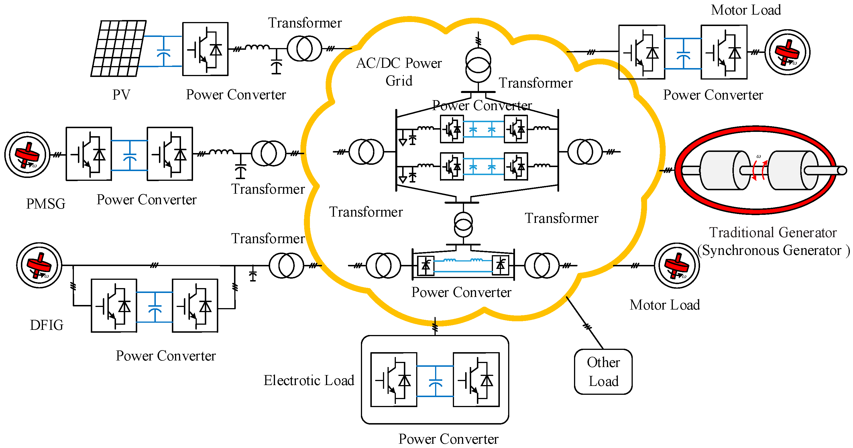
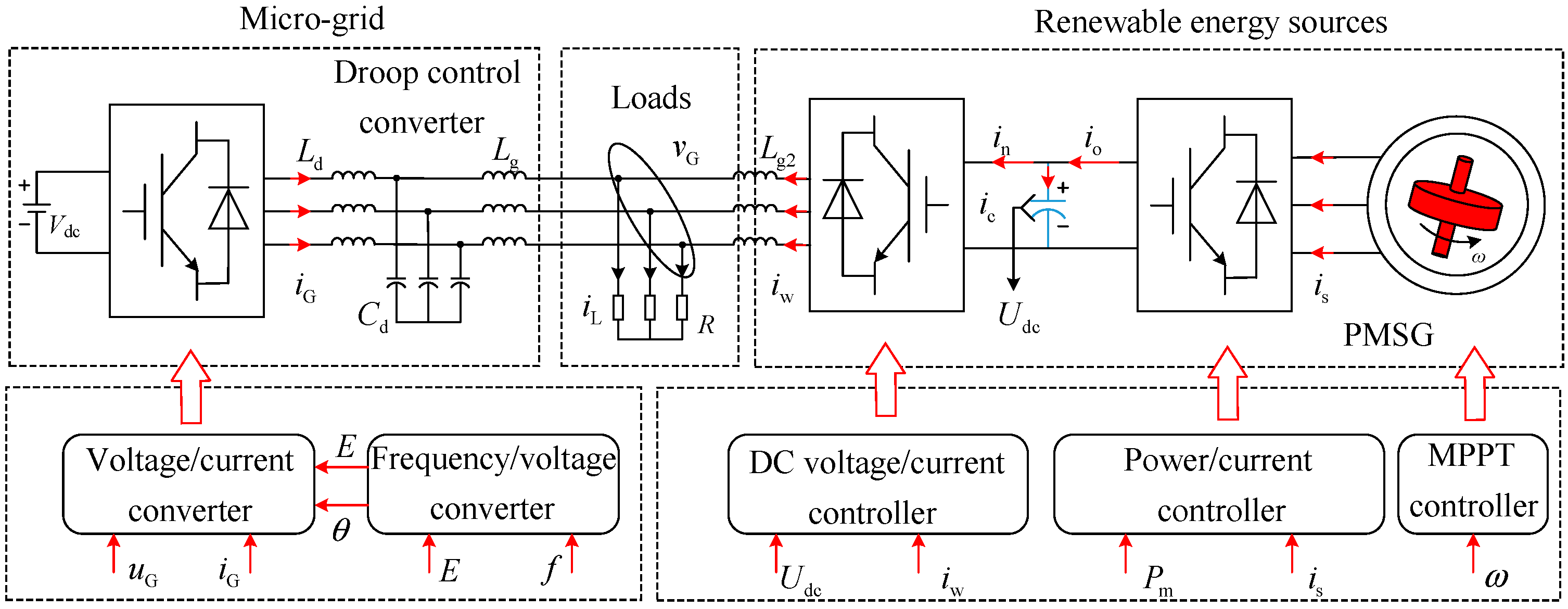
2. Inertial Source Analysis of WT Accessing Micro-Grid System

In order to analyze the inertia characteristics of the system, the direct-drive wind power system is connected to the low-inertia grid. The overall structure of the system is shown in Figure 2, where the low-inertia grid is replaced by a converter system with conventional droop control.
In WT’s micro-grid system, energy storage devices (WTs rotors, DC side capacitors) can be used to provide additional inertia for the system under the action of additional virtual inertia control [10,11,12,13,17,18,19,20]. At the same time, the micro-grid under the droop control can also provide a certain inertia [19,25]. The following is a detailed inertia analysis of the system from the WT, capacitor, and micro-grid simulated by droop control converter.

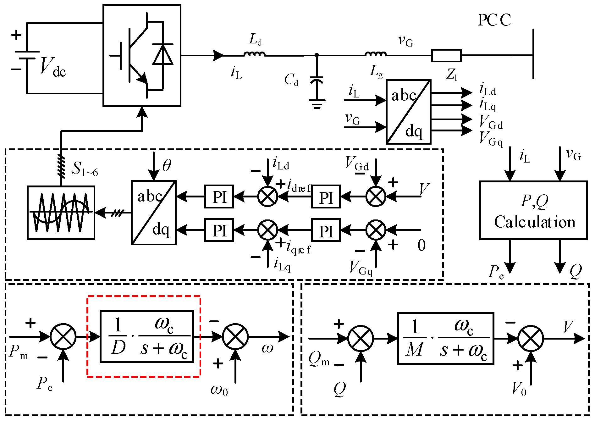
2.1. WTs Side Inertia Characteristic

The principle of virtual inertia control on the WTs side is illustrated in Figure 3. In the figure, ωw is the WTs speed, ωwref is the WTs rated speed, PVIC is the virtual inertia power command, isabc is the stator current, Pref is the MPPT power command, θ is the pitch angle of the wind turbine, and kopt is the coefficient that makes the WT reach the maximum available power [13]. Due to the limitation of the article length, the pitch angle control of the fan can be referred to in the literature [13].
In the MPPT mode, due to the decoupling between the WTs rotor and the system frequency [5,6], the rotor kinetic energy is not involved in the system frequency adjustment. Therefore, on the MPPT control, by introducing the system frequency and PD control, the WTs’ auxiliary power command PVIC for grid inertia support can be generated [13,17]. This power will drive the rotor speed up or down during the transient process to achieve dynamic frequency support. Among them, the auxiliary power command PVIC can be rewritten as
P VIC = k p Δ ω k d d Δ ω d t
where Δω is the system frequency deviation, kp and kd are the PD parameters of the virtual inertia control. When the WTs does not participate in the power grid primary frequency modulation, Equation (1) can be rewritten as
P VIC = k d d Δ ω / d t
For wind turbines with mechanical angular velocities ωw, electrical angular velocities ωew, and poles p, regardless of WTs losses, the rotor kinetic can be expressed as
E k r = J w ω w d ω w = 1 2 J w ω w 2 = 1 2 p 2 J w ω e w 2
When the WTs respond to the system frequency changes, the rotor kinetic change can be expressed as
Δ E k r = 1 2 p 2 J w [ ( ω e w 0 + Δ ω e w ) 2 ω e w 0 2 ] = 1 2 p 2 J v r [ ( ω 0 + Δ ω ) 2 ω 0 2 ]
where ωew0 and ω0 are the WTs initial angular frequency and the system synchronization angular frequency, respectively, Δωew is the WTs angular frequency increment, and Jvr is the equivalent moment of inertia under the virtual inertia control. Jvr is expressed as
J v r = J w ( 2 ω e w 0 + Δ ω e w ) Δ ω e w ( 2 ω 0 + Δ ω ) Δ ω J w Δ ω e w ω e w 0 Δ ω ω 0
The virtual inertia adjustment parameter kr can be defined as
k r = Δ ω e w ω e w 0 / Δ ω ω 0
It can be observed in Equations (4)–(6) that the inertia that the WTs rotor can exhibit is not only related to its own inertia, but also related to the adjustment parameter kr when virtual inertia control is employed. Compared with synchronous generators, due to the large adjustment range of the WTs speed, it can exhibit an equivalent inertia larger than the inherent inertia.
It is considered that the kinetic energy released by the rotor is equal to the auxiliary energy according to the principle of conservation of energy (dΔEkr/dt = PVIC) [13]. When the system frequency does not change much, the relationship between the adjustment coefficients kr and kd can be obtained as follows
k r = p 2 k d ( ω 0 + Δ ω ) J w p 2 k d ω 0 J w
According to the definition of the inertia time constant in the power system [26], the equivalent inertia time coefficient of the WTs system can be expressed as
H v r = J v r ω 0 2 2 p 2 S B = Δ ω e w J w ω e w 0 ω 0 2 2 p 2 Δ ω ω 0 S B = k r J w ω 0 2 2 p 2 S B = k r H w
From Equation (8), the equivalent inertia coefficient under a certain power rating is limited by the following factors: WTs inherent inertia Jw (inertia time constant is H w ), the virtual inertia adjustment parameter kr, and the steady-state operating point (ωe0) of the system. For a 20 kW wind power system with frequency deviation Δf = 0.2 Hz (50 Hz power system), the inertia time constants Hvr versus Jw, kr, and the steady-state operating point (WTs speed ωe0) is illustrated in Figure 4.
It is evident from Figure 4 that the equivalent inertia exhibited by the WTs, under the action of virtual inertia control, is related to multiple parameters, and Hvr increases along with the increases of Jw, ωew0, and kr. Furthermore, it is possible for WTs power to generate even larger equivalent inertia than the inertia produced by synchronous generators. However, larger Jw and ωew0 will inevitably increase the system size and cost, and a higher kr may bring in over modulation issues. Therefore, these factors should be considered comprehensively in practical applications. Since the inherent inertia of the generator rotor has been determined at the time of rotor manufacture, in order to allow the wind power system to participate in system frequency adjustment without increasing energy storage, a feasible solution is to artificially control the rotor speed and system frequency.

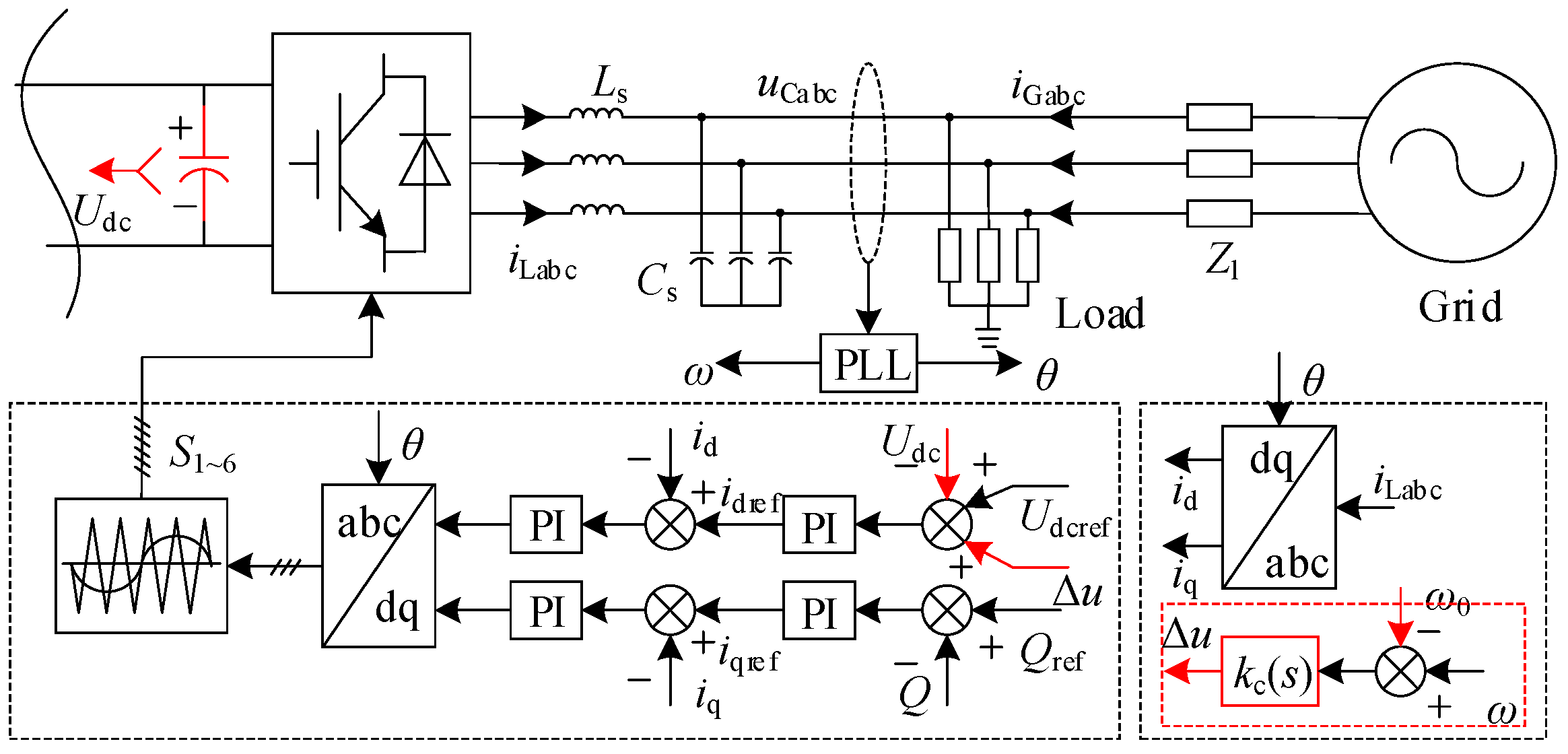
2.2. DC Capacior Side Inertia Characteristic

The principle of virtual inertia control of DC capacitors for grid-connected inverters is illustrated in Figure 5. Where Udc is the DC side capacitor voltage, Ls and Cs, respectively, are the filter inductor and capacitor, ω is the system real-time frequency, and kc(s) is the DC side of virtual inertia controller. By artificially coupling the system frequency, the capacitor involves the system frequency regulation through the dynamic charging and discharging process, in which the charge and discharge effect of the capacitor is externally expressed as the inertia characteristic [17]. Among them, the auxiliary voltage regulation command under the virtual inertia controls as
Δ U d c = k c ( s ) Δ ω
As a typical energy storage equipment component, the capacitor itself can store a certain amount of electric energy. To respond to the system frequency disturbance, this part of energy can be utilized by the virtual inertia control, forcing the capacitor to participate in the dynamic response of the grid frequency.
In steady-state operation, the electrical energy stored in the capacitor can be calculated by
E k c = C d c U d c d U d c = 1 2 C d c U d c 2
where Cdc is the capacitance of the DC side capacitor and Udc is the DC capacitor voltage.
When the DC capacitor responds to the system frequency change, the capacitor’s energy variation ΔEkc can be expressed as
Δ E k c = 1 2 C d c [ ( U d c 0 + Δ U d c ) 2 U d c 0 2 ] = 1 2 C d c [ ( ω 0 + Δ ω ) 2 ω 0 2 ]
where Udc0 is the DC capacitor voltage rating, and C d c is the equivalent capacitance under the control of virtual inertia, which is given by
C d c = C d c ( 2 U d c 0 + Δ U d c ) Δ U d c ( 2 ω 0 + Δ ω ) Δ ω C d c Δ U d c U d c 0 Δ ω ω 0
Similarly, the capacitor virtual inertia adjustment factor k c can be defined as
k c = Δ U d c U d c 0 / Δ ω ω 0
Substituting Equation (9) into Equation (13), the relationship k c between and kc can be obtained as follows:
k c = k c U d c 0 / ω 0
So, the equivalent inertia time coefficient Hvc can be reorganized as
H v c = C d c U d c 0 2 2 S B = Δ U d c C d c U d c 0 U d c 0 2 2 Δ ω ω 0 S B = k c C d c U d c 0 2 2 S B = k c H c
Learning from the analysis method of [17], from Equation (14), the equivalent inertia coefficient is affected by the following factors: DC-link inherent capacitance Cdc (Inertia time constant is H c ), the virtual inertia adjustment parameter kc, and the steady-state operating point Udc of the system. For a 20 kW power converter system with frequency deviation Δf = 0.2 Hz (50 Hz power system), the inertia time constants Hvc versus Cdc, k c , and the steady-state operating point is illustrated in Figure 6.
It is clear from Figure 6 that the equivalent inertia exhibited by the capacitor, under the action of virtual inertia control, is related to multiple parameters, and Hvc increases along with the increases of Cdc, Udc0, and kc. Furthermore, it is possible for power converters to generate even larger equivalent inertia than the inertia produced by synchronous generators. Similarly, larger Cdc and Udc0 will inevitably increase the system size and cost, and a higher kc may bring in over modulation issues. So, these factors should be examined comprehensively in practical applications.
In order to make the capacitor to participate in the system frequency adjustment without increasing the energy storage, a feasible solution is to artificially couple the DC voltage with the system frequency.

2.3. Micro-Grid Side Inertia Characteristic

The grid is simulated by the converter with droop control. So the inertia that the grid can provide is very weak. Figure 7 shows the droop control schematic where Pm and P are rated power, output electromagnetic power, respectively; 1/D and 1/M are active-frequency droop coefficient and reactive-voltage droop coefficient of the power grid, respectively; and ωc denotes the cutoff frequency of the low-pass filter in the droop control loop.
According to Figure 7, the expression of the system frequency under the action of the droop mechanism can be obtained as follows:
ω = ω 0 + 1 D ω c s + ω c ( P m P e ) .
Without considering the input power command change, linearizing Equation (16) can be obtained as
Δ ω = 1 D ω c s + ω c Δ P e .
According to the droop mechanism, the system frequency changes when the load is disturbed, and the power command generated by the system frequency change under the droop action is
Δ P e = D ( s + ω c ω c ) Δ ω = D ( s ω c + 1 ) Δ ω = Δ P e + Δ P 1
where Δ P e and Δ P 1 are transient power and steady-state power, respectively. Equation (18) shows that under the action of the droop mechanism, the power in response to the frequency change of the system consists of two parts, wherein the transient part corresponds to the inertia effect of the system, and the steady-state part corresponds to the damping part of the system. The transient power Δ P e is
Δ P e = D s ω c Δ ω .
For Equation (19), the transient support energy under the droop control is
Δ E gk = D ω c Δ ω .
So, the inertia time constant corresponding to the droop control can be defined as
H g = Δ E gk S B = D S B ω c Δ ω .
For the same reason, it can be known from Equations (19)–(21) that the droop control analog grid has a certain inertia effect. Equation (21) denotes that the equivalent inertia coefficient is affected by the following factors: the droop coefficient D and the cutoff frequency ωc. For a 20 kW power converter system with frequency deviation Δf = 0.2 Hz (50 Hz power system), the inertia time constants Hg versus D, and ωc is illustrated in Figure 8.
According to the analysis of Section 2.1, Section 2.2 and Section 2.3, the factors affecting the system inertia are related to the steady-state operating point of the system and the structural parameter control parameters. However, it is worth noting that the maximum power of the WT is closely related to the steady-state operating point of the WT, that is, the optimal operating point is determined by the WT itself, and cannot change arbitrarily. Similarly, the frequency modulation system and structural parameters of the micro-grid are not arbitrarily changeable. It is financially feasible to increase the system to obtain hidden inertia by means of control without increasing the operating cost.

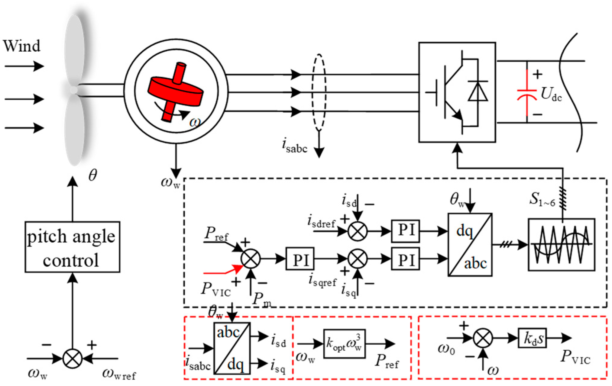
3. Analysis of Inertia Characteristics of Direct-Drive Wind Power Grid-Connected System

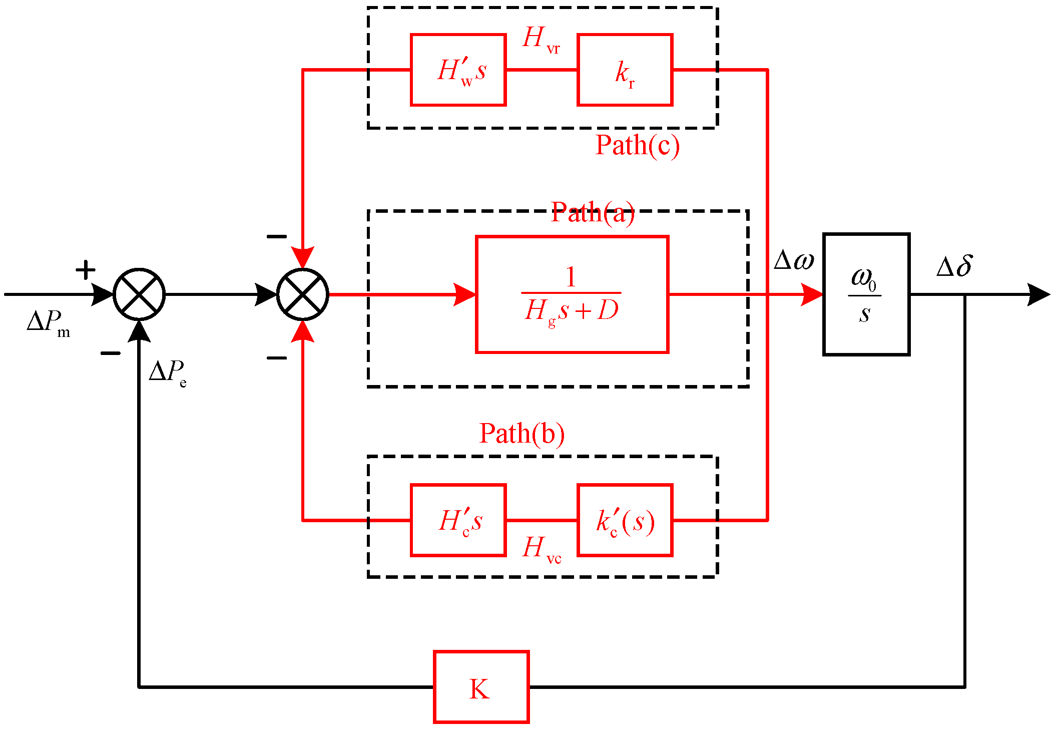
3.1. System Inertia Characteristic Mechanism

According to the system structure diagram shown in Figure 2 and Equations (8), (15) and (21), the equivalent Heffron–Philips model can be obtained, as shown in Figure 9.
According to the equivalent model shown in Figure 9, using the electrical torque analysis method, the mathematical expression of the system equivalent Heffron–Philips model can be obtained as
{ d Δ δ d t = ω 0 Δ ω T J Σ d Δ ω d t = T D Δ ω T S Δ δ
where TJ is the equivalent inertia time coefficient of the system, TD is the equivalent damping time coefficient of system, and TS is the equivalent synchronization time coefficient of system. TJ, TD, and TS can be expressed, respectively, as
{ T J Σ = H vr + H vc + H g = 1 S B ( k r J w ω 0 2 2 p 2 + k c C d c U d c 0 2 2 + D Δ ω ω c ) T D = D T S = 3 2 U s U g X cos δ 0
From Figure 9 and Equation (23), the system inertia TJ effect has three active paths.
Path (a) corresponds to the droop control of the low-inertia grid. As shown in Figure 7, the droop mechanism in the frequency outer loop control of grid side can slow down the frequency variation to provide frequency support for the system.
Path (b) corresponds with the DC capacitor inertia effect, which is generated by the intrinsic inertia and the inertia control of DC capacitor simultaneously. The DC capacitor actively charges and discharges in response to the system frequency change to provide transient support for the system frequency.
Path (c) corresponds with the rotor inertia effect (inherent inertia and control). WTs rotor speed transient increases or decreases to provide transient support for the system frequency (by action of virtual control).

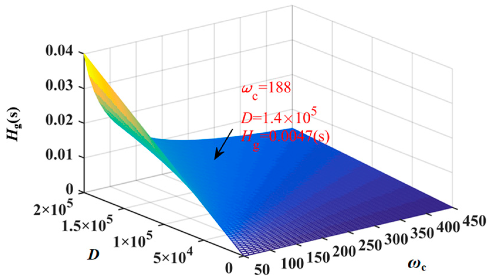
3.2. System Inertia Analysis

According to the equivalent model shown in Figure 9, the transfer function of the load and system frequency response can be expressed as
Δ ω Δ P e = 1 D 1 T J Σ / D s + 1 .
The equivalent inertia coefficient has frequency domain characteristic when the DC capacitor control function kc(s) has a frequency characteristic. The characteristic of kc(s) under different property function is analyzed as follows:
(1) The function kc(s) is a proportional coefficient, that is to say
k c ( s ) = k p .
The capacitor voltage under proportional control is changed to participate in system frequency support. When the system is subjected to load disturbance, the frequency curve under different control parameters is shown in Figure 10.
It can be observed in Figure 10 that the frequency change rate tends to infinity when subjected to load disturbance due to the lack of inertia of the system. A large rate of change of frequency (RoCoF) may trigger a relay protection action, which does not contribute to safe and stable operation of the system. A larger inertia can cause the RoCoF to decrease as shown by the green and red curves in Figure 10.
(2) The function kc(s) is a high-pass filter link, namely
k c ( s ) = k p ω s s s + ω s
where ωs is the cutoff frequency of the high-pass filter.
The inertia exhibited by the system will no longer be a constant parameter because of the flexibility and controllability of the power electronics system (bring Equation (26) into Equation (23)). In other words, the inertia changes with time-scale and frequency change. The amplitude-frequency and phase-frequency characteristics of the system are shown in Figure 11.
It is clear from Figure 11 that the system equivalent inertia has frequency characteristic (blue, green, and red curves indicate that control parameters increase in turn). The amplitude-frequency characteristic of the system inertia is positive in the middle and high frequency bands. The frequency changes rapidly during the transient process when a load shock occurs in the system. The high frequency signal under the control of the virtual inertia excites large inertia effect, forcing the capacitor to react to the frequency change. The frequency is almost constant when the system enters steady state. The low frequency signal under the virtual inertia control can hardly excite the inertia effect, that is, the capacitor does not reply to the system frequency change during steady state.
The capacitor voltage is forced to rise or fall during the transient process in response to the system frequency change. When the system is subjected to load disturbance, the frequency curve under different control parameters is shown in Figure 12.
Both proportional control and high-pass filter control allow the DC capacitor to provide inertia to the system through voltage changes, as shown in Figure 12. When the load disturbance occurs (the grid secondary frequency modulation does not work), the capacitor voltage cannot be restored to the rated value under proportional control. At the same time, the capacitor voltage may affect the normal operation of the inverter. As shown by the red line in Figure 12, the high-pass filter control avoids voltage drops, but the frequency response time increases from 2.3 s to 3.8 s, and the lowest frequency deviation varies from 0.1 Hz to 0.12 Hz. In realistic applications, the DC capacitor control function kc(s) should be selected according to the system operation requirements.

4. Simulation Result and Analysis

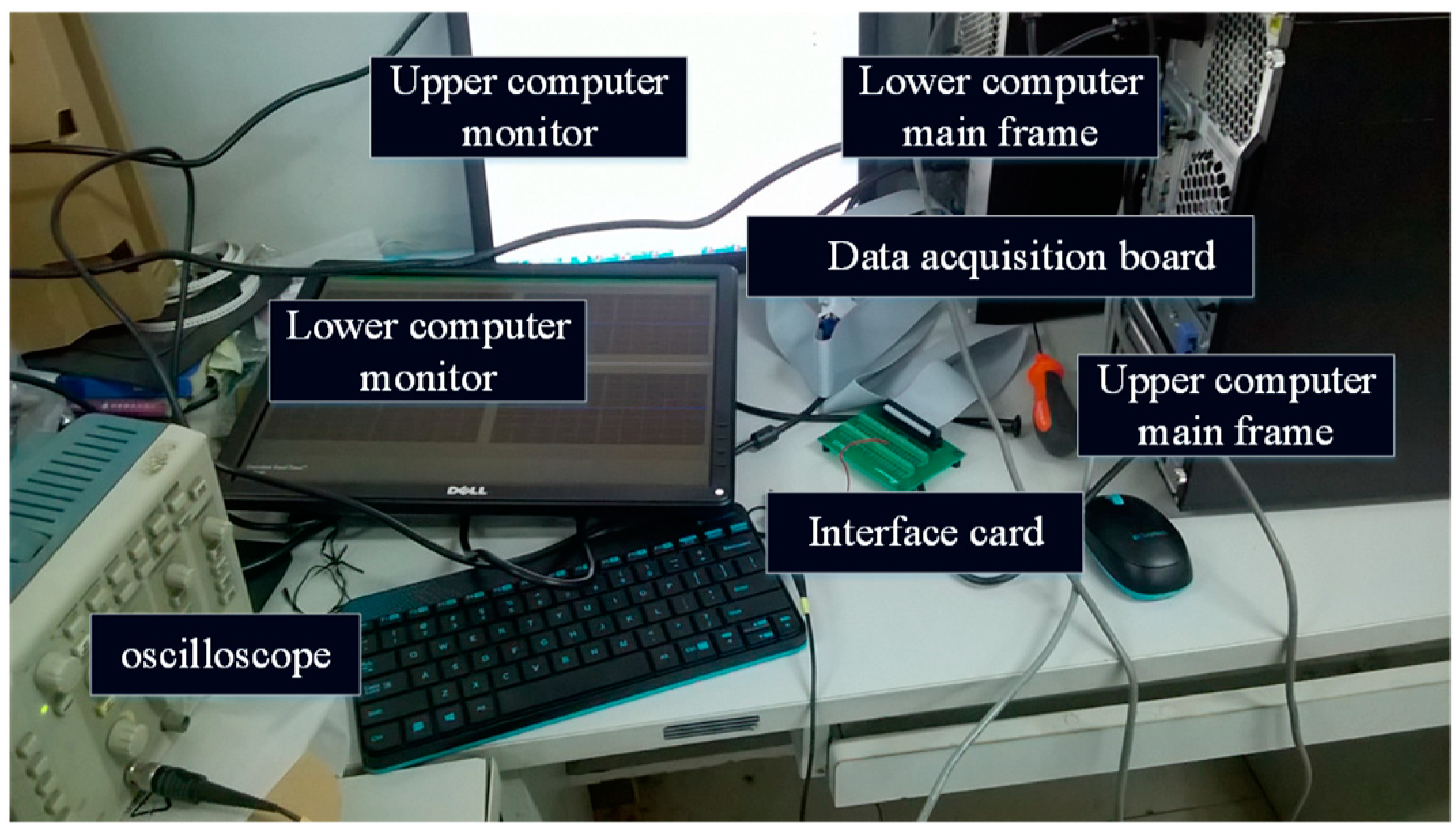
4.1. Simulation Settings

The correctness of the system inertia characteristics is verified by the MATLAB/Simulink, and the experimental platform is built by simulink real-time. The parameters of real-time simulation platform are consistent with the parameters of MATLAB/SIMULINK simulation model. The real-time simulation platform is shown in Figure 13. The real-time simulation platform comprises of main frames, monitors, a date acquisition board, and an interface board. The simulation model is calculated and run by the upper computer main frame; MATLAB/SIMULINK was used to implement the control algorithms of both the WT system and micro-grid; and the curves are shown by the lower computer monitor. The oscilloscope records the relevant waveform through the interface board. The structure of the simulation system is illustrated in Figure 2. The simulation and experiment parameters of the system are shown in Table 1.
At startup, the wind power system and the grid share a 40 kW load, and the load increases by 20 kW in 3 s, and the load is removed at 6 s. During this period, the secondary frequency modulation of the grid and the primary frequency modulation of the WT are not considered.

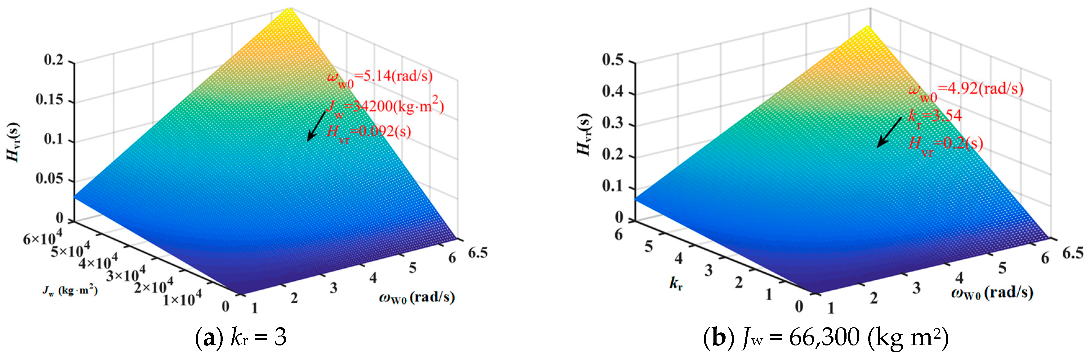
4.2. Inertia Characteristic Analysis and Verification

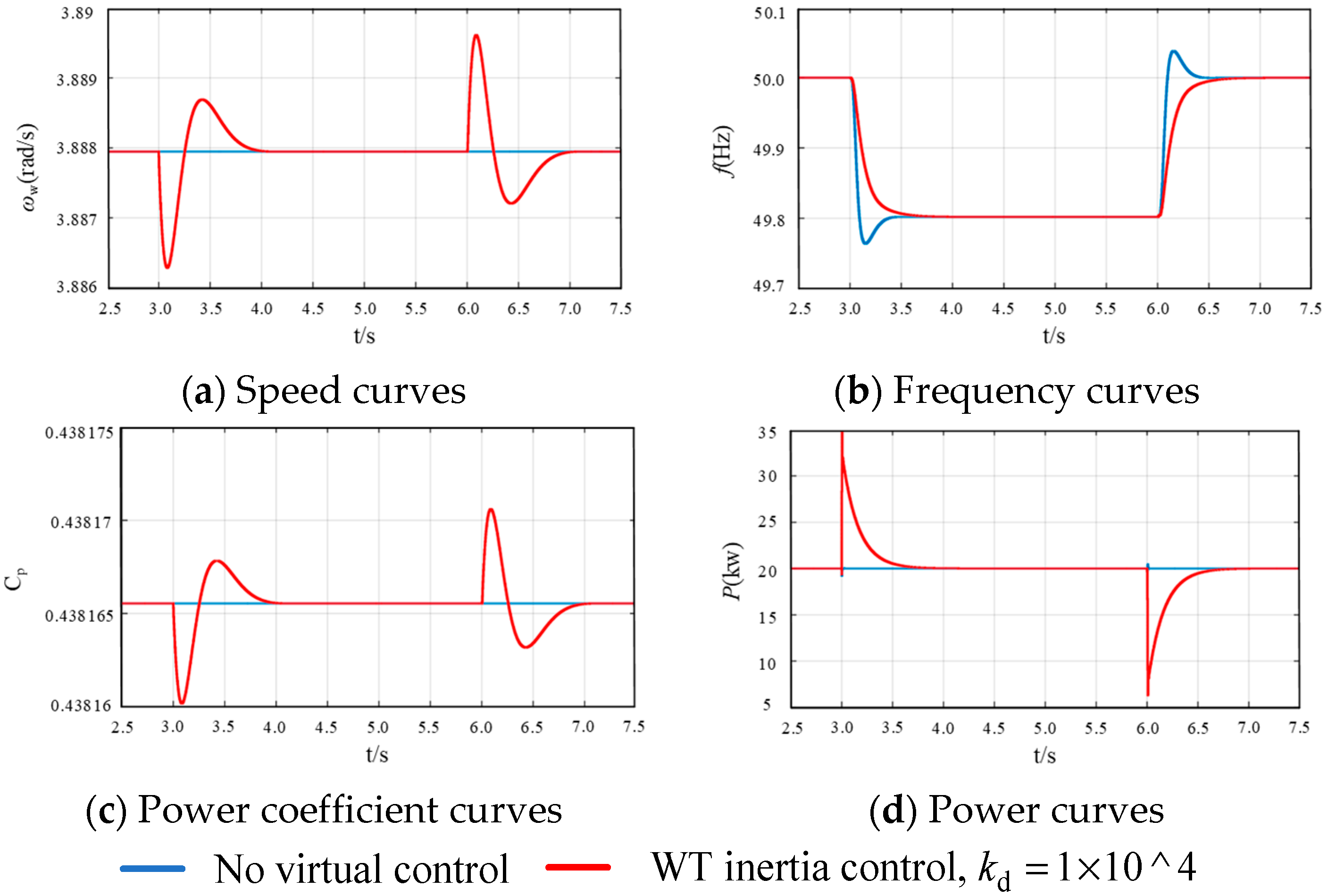
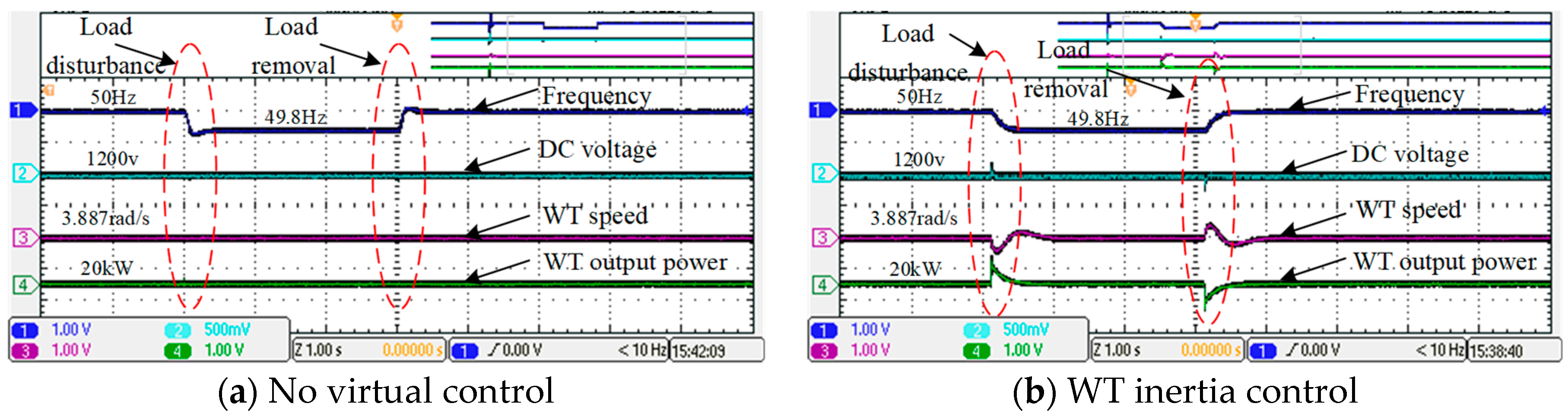
4.2.1. Analysis of Side Inertia Characteristics of WT

When the load disturbance occurs in the system, under the virtual inertia control of the WT, the simulation results of the system response curve are illustrated in Figure 14. Figure 14a is the WT generator rotor speed curve; Figure 14b is the system frequency curve; Figure 14c is WT power coefficient; and Figure 14d is the WT output power curve. The blue curve in the figure indicates the output characteristic curve when the system is not using virtual inertia control, and the red curve indicates the output characteristic curve when the WT is monitored by virtual inertia.
As shown in Figure 14a, when the WT is subjected to virtual inertia control under load disturbance, the rotor speed changes in response to the system frequency change. At this time, the system frequency RoCoF decreases as shown in Figure 14b, and the speed change makes the wind turbine utilize the coefficient Cp changes as shown in Figure 14c. At this time, WT output transient power does increase (or decrease) as shown in Figure 14d, indicating that the rotor responds to the system frequency change by releasing or storing kinetic energy.
Experimental results in Figure 15a shows the output characteristic curve when the WT is not added with the virtual inertia control, and Figure 15b the output characteristic curve when the WT side adopts the virtual inertia control, including the system frequency curve, the DC voltage curve, the rotor speed curve, and the WT output power curve. Consistent with the above analysis, the virtual inertia control of the WT can increase the system inertia at the cost of fluctuations in the WT speed.

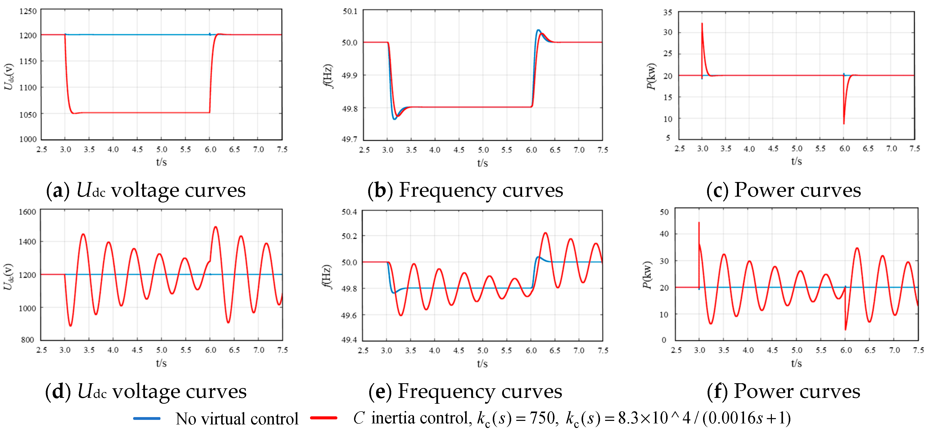
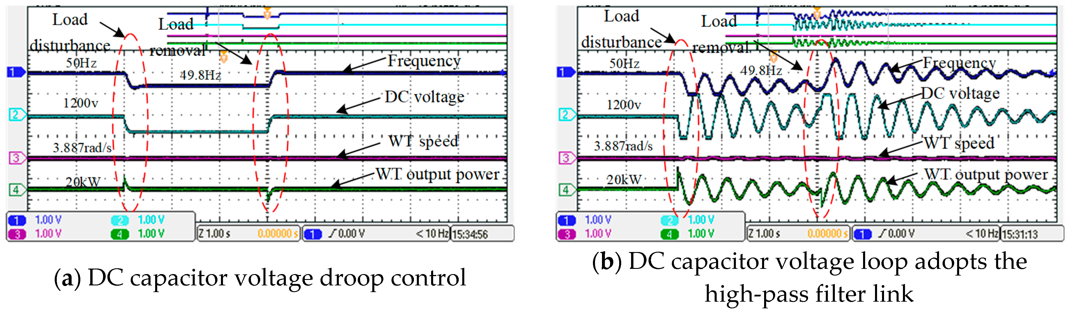
4.2.2. Analysis of Side Inertia Characteristics of Capacitor

Shown in Figure 16a–c is the DC voltage curve, the system frequency curve, and the WT output power curve when the DC capacitor voltage is drooped. It can be seen from Figure 16a that the frequency deviation is maintained at 0.2 Hz under load disturbance, which causes the DC bus voltage to go to a low level (1050 v). This is the same as the virtual inertia of the rotor of the WT, and the system frequency response is improved as shown in Figure 16b. The output power of the wind power system increases (or decreases) as shown in Figure 16c.
As shown in Figure 16a, although DC inertia control by DC voltage droop control can increase the system inertia, it will cause deviation of the DC bus. If the frequency changes greatly, the lower bus voltage is not involved in system operation. In order to enable the DC bus voltage to recover to the rated value, the DC voltage virtual inertia control uses a high-pass filtering link, as shown in Figure 16d–f, for the frequency disturbance, and the high-pass filter link for the wind power generation system. DC voltage curve, system frequency curve and output power curve.
Experimental results are shown in Figure 17 when the virtual inertia control of the WT is not considered. Figure 17a is the output characteristic of the DC capacitor voltage droop control, and Figure 17b is the output characteristic curve when the DC capacitor voltage loop adopts the high-pass filter link.
When the DC voltage is controlled by the high-pass filter, the DC bus voltage can be restored to the rated value when subjected to load disturbance, as shown in Figure 16d (or Figure 17b), and the frequency characteristics of the system can be improved (frequency change first pendulum). The rate of change is reduced as shown in Figure 16e; however, the trouble caused by such control is that the system will oscillate, including DC bus voltage oscillation, system frequency oscillation, and output power oscillation.

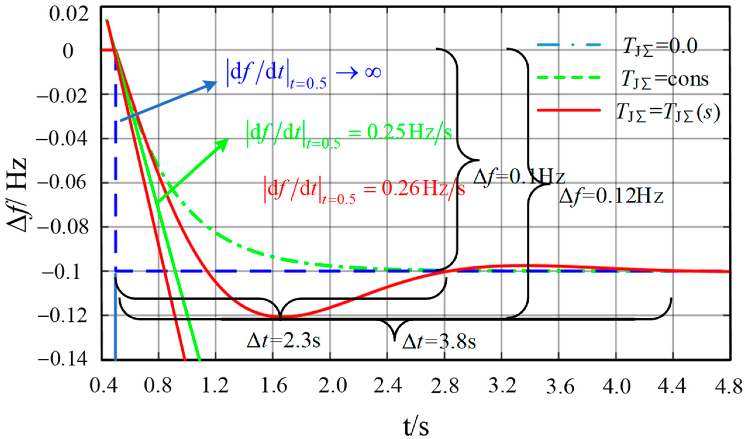
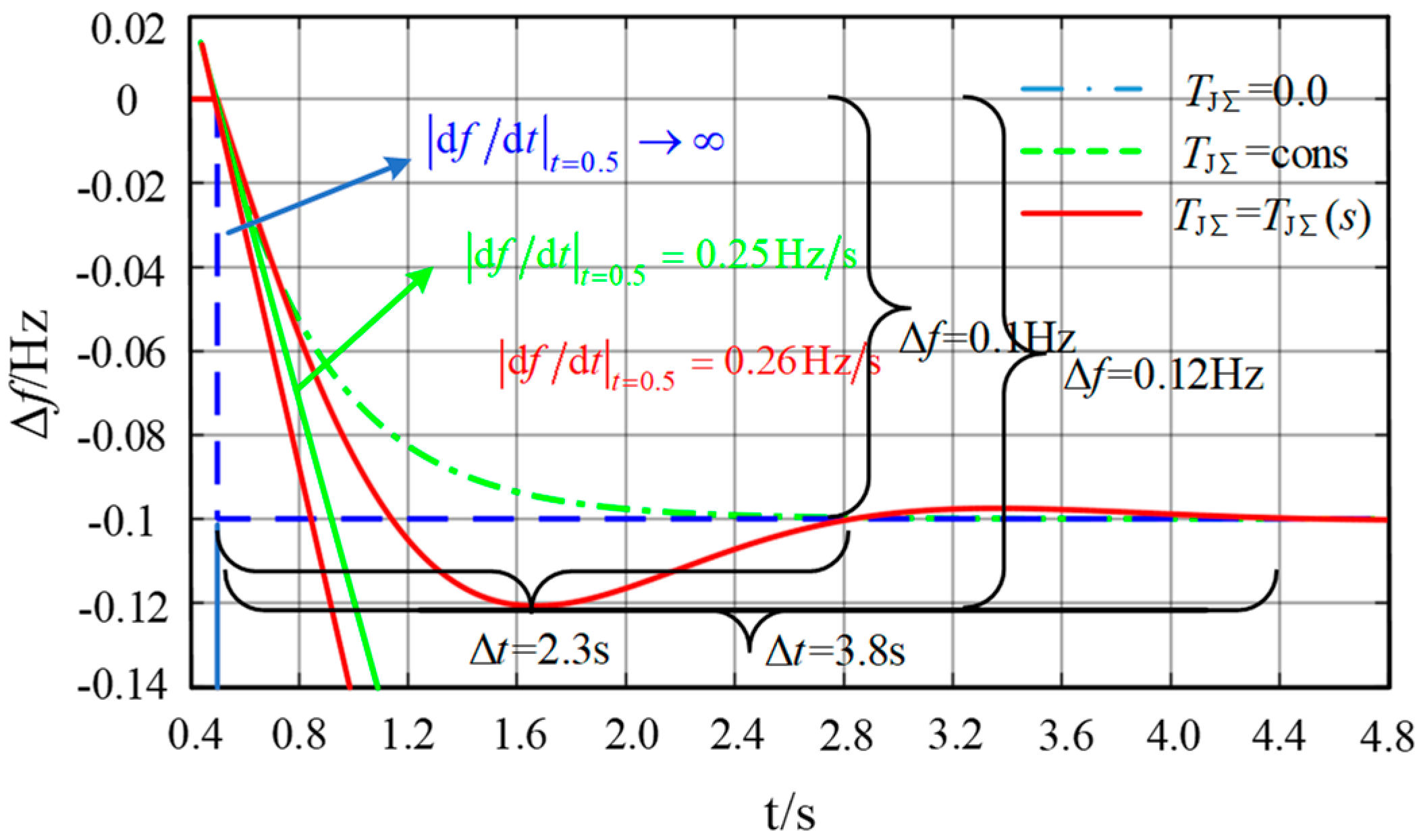
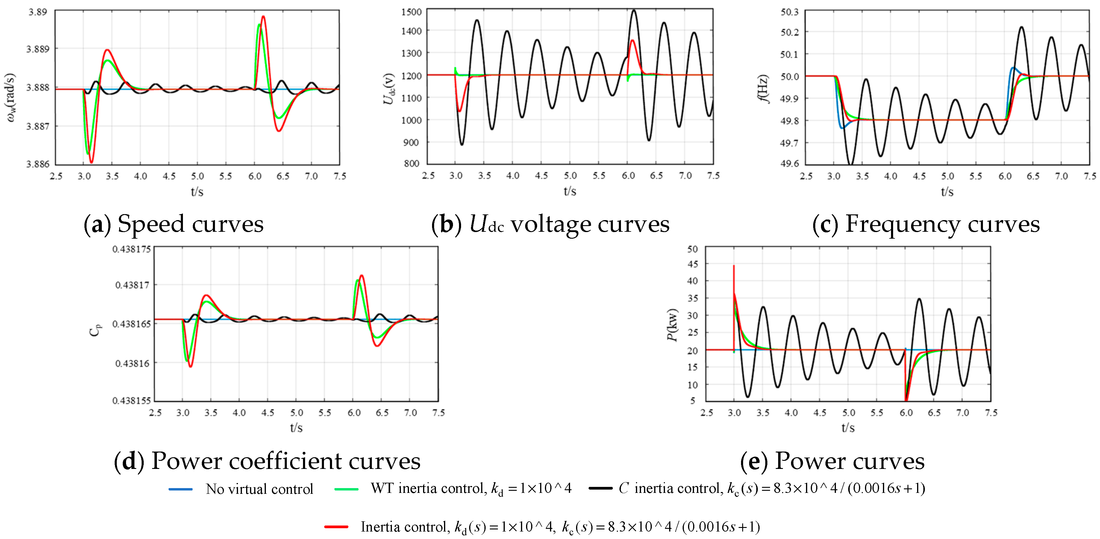
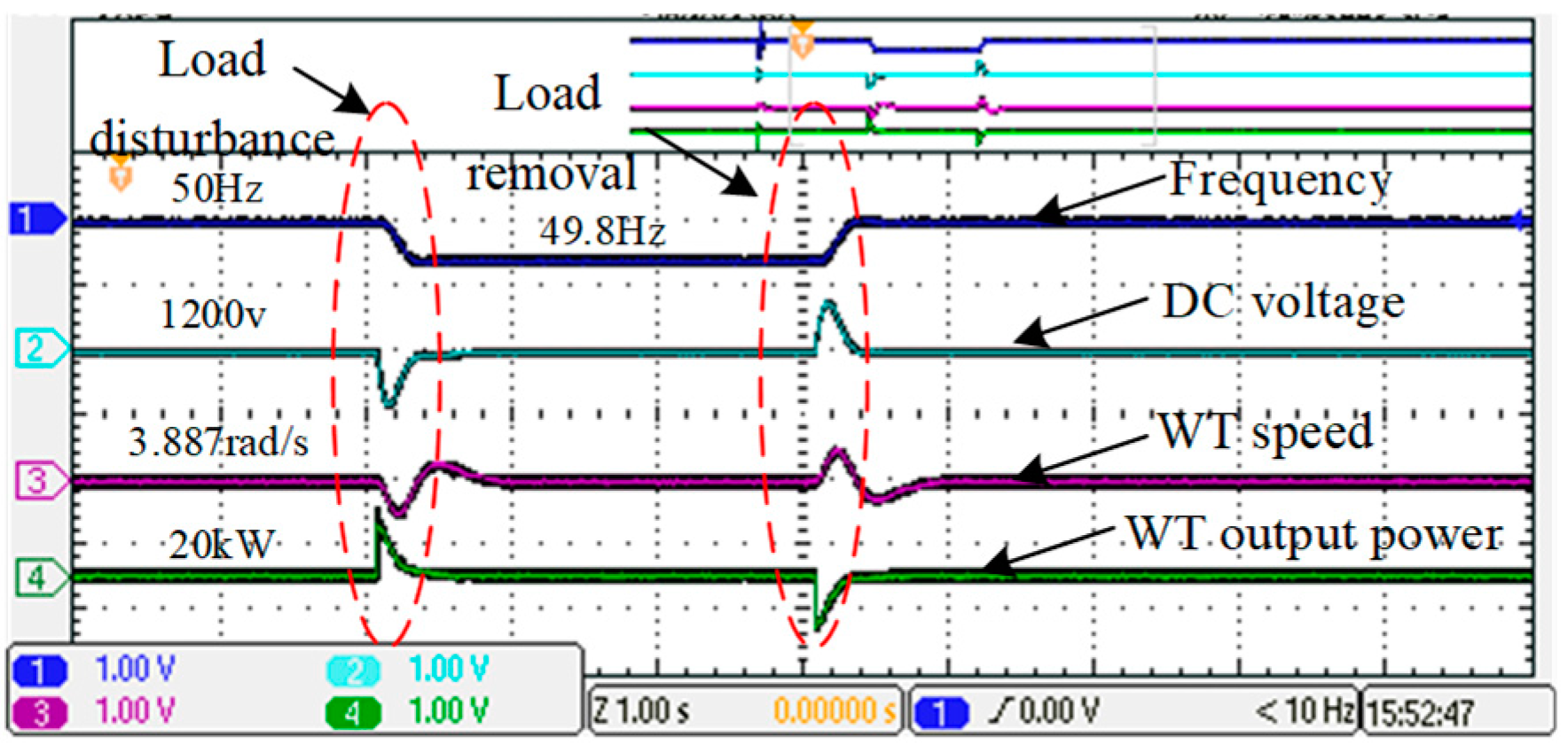
4.2.3. Analysis of Inertia Characteristics under the Coordination of WT and Capacitor

In WT power systems, both WT rotors and DC capacitors provide auxiliary inertia characteristics to the system. To take full advantage of the energy of these two components, both the rotor and DC capacitors of the WT are inertially controlled. For the WT rotor, the kinetic energy retained by the rotor has a high energy density, but the release rate is slow, and the capacitor energy density is low but the release speed is extreme. As shown in Figure 18, the output characteristics of the rotor and capacitor are controlled by inertia. Load disturbances (Figure 18a–e) are rotor speed curves, the DC voltage curves, the micro-grid system frequency curves and the WT energy utilization coefficients, and the WT system curves of output power. As can be seen from the figure, when the rotor and capacitor voltages are controlled by inertia, the system can obtain large inertia characteristics, as shown by the red line in the figure. With the support of rotor energy, compared with the unique capacitive inertia control, the DC bus voltage fluctuation is also reduced, the system frequency change rate is also significantly decreased, and the system dynamic performance is improved.
Experimental results in Figure 19 show the output characteristics when the virtual inertia of the WT is coordinated with the DC capacitance inertia. Comparing Figure 16, it can be seen that after making full use of the WT’s moment of inertia and capacitive inertia, the output characteristics of the system and the inertia level is improved.

5. Conclusions

In this paper, the direct-drive WTs power generation system is taken as the research object, and inertia characteristics of the WTs connected to the micro-grid are analyzed. The following conclusions are obtained by theoretical analysis and simulation comparison:
(1) Under the virtual inertia control, the energy storage device in the system—the rotor of the WT and the DC-side capacitor can exhibit inertial characteristics. The inertia characteristics of WT and capacitors depend on the state of the system during steady-state operation and the control action. The inertia of the WT can cope with relatively large frequency changes, while the capacitor can respond to small frequency changes.
(2) Compared with the inherent inertia of generator in traditional power system, under the control of virtual inertia, the equivalent inertia of the micro-grid system will be generated by multiple channels (WT rotor, DC capacitor, and droop mechanism), not limited to a single unit of the power generation system.
(3) Compared with the additional energy storage device, by utilizing the energy storage equipment in the micro-grid system, a certain inertia characteristic can be provided only by simple control action, and no additional energy storage device is used to reduce the economic cost.

Author Contributions

All the authors conceived and designed the study. D.Z. and Y.W. performed the theoretical analysis and wrote the manuscript with the guidance from Professor L.X. and C.Z.; D.Z. and Y.W. conceived and designed the simulation experiments.

Funding

This study is supported by the State Key Laboratory of Alternate Electrical Power System with Renewable Energy Sources (Grant No. LAPS19008) and the National Natural Science Foundation of China (Grant No. 51707091).

Conflicts of Interest

The authors declare no conflict of interest.

References

  1. Blaabjerg, F.; Teodorescu, R.; Liserre, M.; Timbus, A.V. Overview of Control and Grid Synchronization for Distributed Power Generation Systems. IEEE Trans. Ind. Electron. 2006, 53, 1398–1409. [Google Scholar] [CrossRef] [Green Version]
  2. Zhao, M.; Yuan, X.; Hu, J. Modeling of DFIG Wind Turbine Based on Internal Voltage Motion Equation in Power Systems Phase-Amplitude Dynamics Analysis. IEEE Trans. Power Syst. 2018, 33, 1484–1495. [Google Scholar] [CrossRef]
  3. Delille, G.; Francois, B.; Malarange, G. Dynamic frequency control support by energy storage to reduce the impact of wind and solar generation on isolated power system’s inertia. IEEE Trans. Sustain. Energy 2012, 3, 931–939. [Google Scholar] [CrossRef]
  4. Carrasco, J.M.; Franquelo, L.G.; Bialasiewicz, J.T.; Galvan, E.; Guisado, R.C.P.; Prats, M.A.M.; Leon, J.I.; Moreno-Alfonso, N. Power electronic systems for the grid integration of renewable energy sources: A survey. IEEE Trans. Ind. Electron. 2006, 53, 1002–1016. [Google Scholar] [CrossRef]
  5. Conroy, J.F.; Watson, R. Frequency Response Capability of Full Converter Wind Turbine Generators in Comparison to Conventional Generation. IEEE Trans. Power Syst. 2008, 23, 649–656. [Google Scholar] [CrossRef]
  6. Mauricioj, M.; Marano, A.; Gomez-Exposito, A. Frequency regulation contribution through variable speed wind energy conversion systems. IEEE Trans. Power Syst. 2009, 24, 173–180. [Google Scholar] [CrossRef]
  7. Zhong, Q.; Weiss, G. Synchronverters: Inverters That Mimic Synchronous Generators. IEEE Trans. Ind. Electron. 2011, 58, 1259–1267. [Google Scholar] [CrossRef]
  8. Liu, J.; Miura, Y.; Ise, T. Comparison of dynamic characteristics between virtual synchronous generator and droop control in inverter based distributed generators. IEEE Trans. Power Syst. 2016, 31, 3600–3611. [Google Scholar] [CrossRef]
  9. Natarajan, V.; Weiss, G. Synchronverters with better stability due to virtual inductors, virtual capacitors, and anti-windup. IEEE Trans. Ind. Electron. 2017, 64, 5994–6004. [Google Scholar] [CrossRef]
  10. Ping-Kwan, K.; Pei, L.; Banakar, H.; Ooi, B.T. Kinetic energy of wind-turbine generators for system frequency support. IEEE Trans. Power Syst. 2009, 24, 279–287. [Google Scholar] [CrossRef]
  11. Arani, M.F.M.; El-Saadany, E.F. Implementing virtual inertia in DFIG-based wind power generation. IEEE Trans. Power Syst. 2013, 28, 1373–1384. [Google Scholar] [CrossRef]
  12. Gautam, D.; Goel, L.; Ayyanar, R.; Vittal, V.; Harbour, T. Control strategy to mitigate the impact of reduced inertia due to doubly fed induction generators on large power systems. IEEE Trans. Power Syst. 2011, 26, 214–224. [Google Scholar] [CrossRef]
  13. Li, H.; Zhang, X.; Wang, V.; Zhu, X. Virtual inertia control of DFlG-based wind turbine based on the optimal power tracking. Proc. CSEE 2012, 32, 32–39. [Google Scholar]
  14. He, W.; Yuan, X.; Hu, J. Inertia Provision and Estimation of PLL-Based DFIG Wind Turbines. IEEE Trans. Power Syst. 2017, 32, 510–521. [Google Scholar] [CrossRef]
  15. Tan, S.; Geng, H.; Yang, G. Phillips-Heffron model for current-controlled power electronic generation unit. J. Mod. Power Syst. Clean Energy 2018, 6, 582–594. [Google Scholar] [CrossRef]
  16. Ma, J.; Qiu, Y.; Li, Y.; Zhang, W.; Song, Z.; Thorp, J.S. Research on the impact of DFIG virtual inertia control on power system small-signal stability considering the phase-locked loop. IEEE Trans. Power Syst. 2017, 32, 2094–2105. [Google Scholar] [CrossRef]
  17. Fang, J.; Li, H.; Tang, Y.; Blaabjerg, F. On the Inertia of Future More-Electronics Power Systems. IEEE Trans. Power Electron. 2018, 34, 5416–5438. [Google Scholar] [CrossRef]
  18. Fang, J.; Li, H.; Tang, Y.; Blaabjerg, F. Distributed Power System Virtual Inertia Implemented by Grid-Connected Power Converters. IEEE Trans. Power Electron. 2018, 33, 8488–8499. [Google Scholar] [CrossRef]
  19. Xiong, L.; Zhuo, F.; Wang, F.; Liu, X.; Chen, Y.; Zhu, M. Static synchronous generator model: A new perspective to investigate dynamic characteristics and stability issues of grid-tied PWM inverter. IEEE Trans. Power Electron. 2016, 31, 6264–6280. [Google Scholar] [CrossRef]
  20. Wu, Y.; Zhang, D.; Xiong, L.; Wang, S.; Xu, Z.; Zhang, Y. Modeling and Mechanism Investigation of Inertia and Damping Issues for Grid-Tied PV Generation Systems with Droop Control. Energies 2019, 12, 1985. [Google Scholar] [CrossRef]
  21. Fang, J.; Tang, Y.; Li, H.; Li, X. A battery/ultracapacitor hybrid energy storage system for implementing the power management of virtual synchronous generators. IEEE Trans. Power Syst. 2018, 33, 2820–2824. [Google Scholar] [CrossRef]
  22. Xiu, L.; Xiong, L.; Yang, P.; Kang, Z. Inertial and damping characteristics of DC distributed power systems based on frequency droop control. Energies 2018, 11, 2418. [Google Scholar] [CrossRef]
  23. Ying, J.; Yuan, X.; Hu, J.; He, W. Impact of Inertia Control of DFIG-Based WTS on Electromechanical Oscillation Damping of SG. IEEE Trans. Power Syst. 2018, 33, 3450–3459. [Google Scholar] [CrossRef]
  24. He, J.; Wu, K.; Huang, L.; Xin, H.; Lu, C.; Wang, H. A Coordinated Control Scheme to Realize Frequency Support of PMSG-Based Wind Turbines in Weak Grids. In Proceedings of the 2018 IEEE Power Energy Society General Meeting (PESGM), Portland, OR, USA, 5–10 August 2018. [Google Scholar] [CrossRef]
  25. Meng, X.; Liu, J.; Liu, Z. A generalized droop control for grid supporting inverter based on comparison between traditional droop control and virtual synchronous generator control. IEEE Trans. Power Electron. 2019, 6, 5416–5438. [Google Scholar] [CrossRef]
  26. Kundur, P.; Balu, N.J.; Lauby, M.G. Power System Stability and Control; McGraw-Hill Education: New York, NY, USA, 1994; ISBN 9780070359581. [Google Scholar]
Figure 1. The future power electronics dominated power systems.
Energies 12 03141 g001
Figure 2. The micro-grid system and renewable energy sources.
Energies 12 03141 g002
Figure 3. The virtual inertia control of the wind turbines (WTs).
Energies 12 03141 g003
Figure 4. Analysis of factors affecting virtual inertia.
Energies 12 03141 g004
Figure 5. DC capacitor virtual inertia controller.
Energies 12 03141 g005
Figure 6. Analysis of factors affecting C virtual inertia.
Energies 12 03141 g006
Figure 7. Micro-grid droop control principle.
Energies 12 03141 g007
Figure 8. Analysis of factors affecting grid inertia of droop control.
Energies 12 03141 g008
Figure 9. Equivalent Heffron–Philips model for grid-connected systems.
Energies 12 03141 g009
Figure 10. Frequency variation curve during load disturbance.
Energies 12 03141 g010
Figure 11. Equivalent inertia amplitude and phase characteristics.
Energies 12 03141 g011
Figure 12. Frequency variation curve during load disturbance.
Energies 12 03141 g012
Figure 13. The real-time simulation platform.
Energies 12 03141 g013
Figure 14. Inertia characteristic analysis and verification of WT.
Energies 12 03141 g014
Figure 15. Inertia characteristic analysis and verification of WT.
Energies 12 03141 g015
Figure 16. Inertia characteristic analysis and verification of DC capacitor.
Energies 12 03141 g016
Figure 17. Inertia characteristic analysis and verification of WT.
Energies 12 03141 g017
Figure 18. Inertia characteristic analysis and verification.
Energies 12 03141 g018
Figure 19. Inertia characteristic analysis and verification.
Energies 12 03141 g019
Table 1. System parameter values.
SystemParametersValueParametersValue
Wind powerSB20 kVAUdc1200 V
Cdc3.4 mFkd1 × 104
Jw3.6 × 104 kg m2kc750
Grid powerP020 kWLs3 mH
1/D1.2 × 10−5Cs50 µF
U0690 Vf50 Hz

