Design and Optimization of an Integrated Turbo-Generator and Thermoelectric Generator for Vehicle Exhaust Electrical Energy Recovery


Abstract
1. Introduction
2. Exhaust Gas Heat Recovery Technology
3. Turbo-Generators and Thermoelectric Generator Modeling
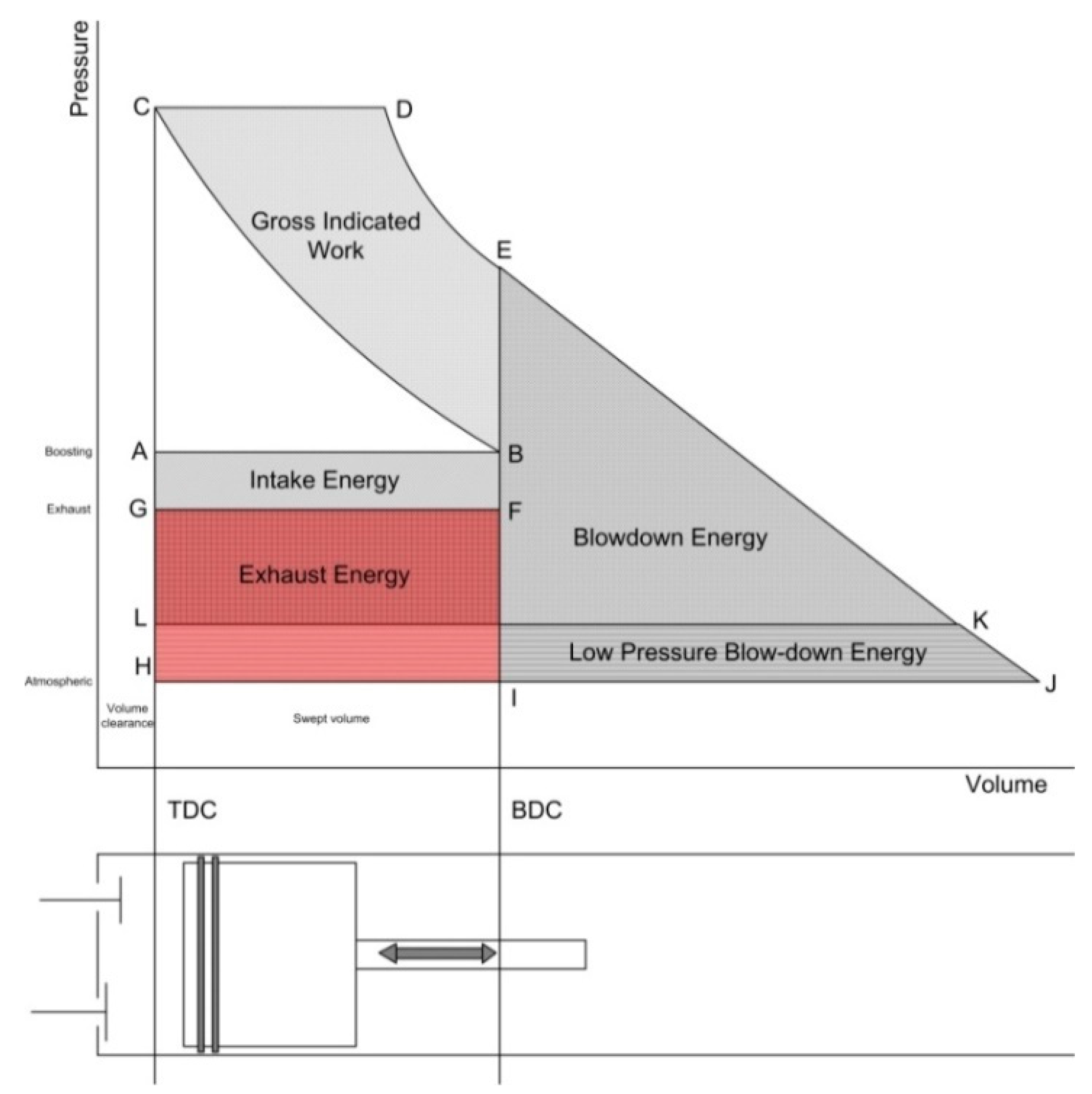
3.1. Exhaust Energy
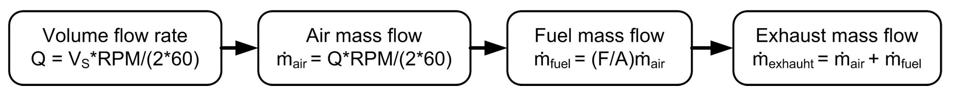
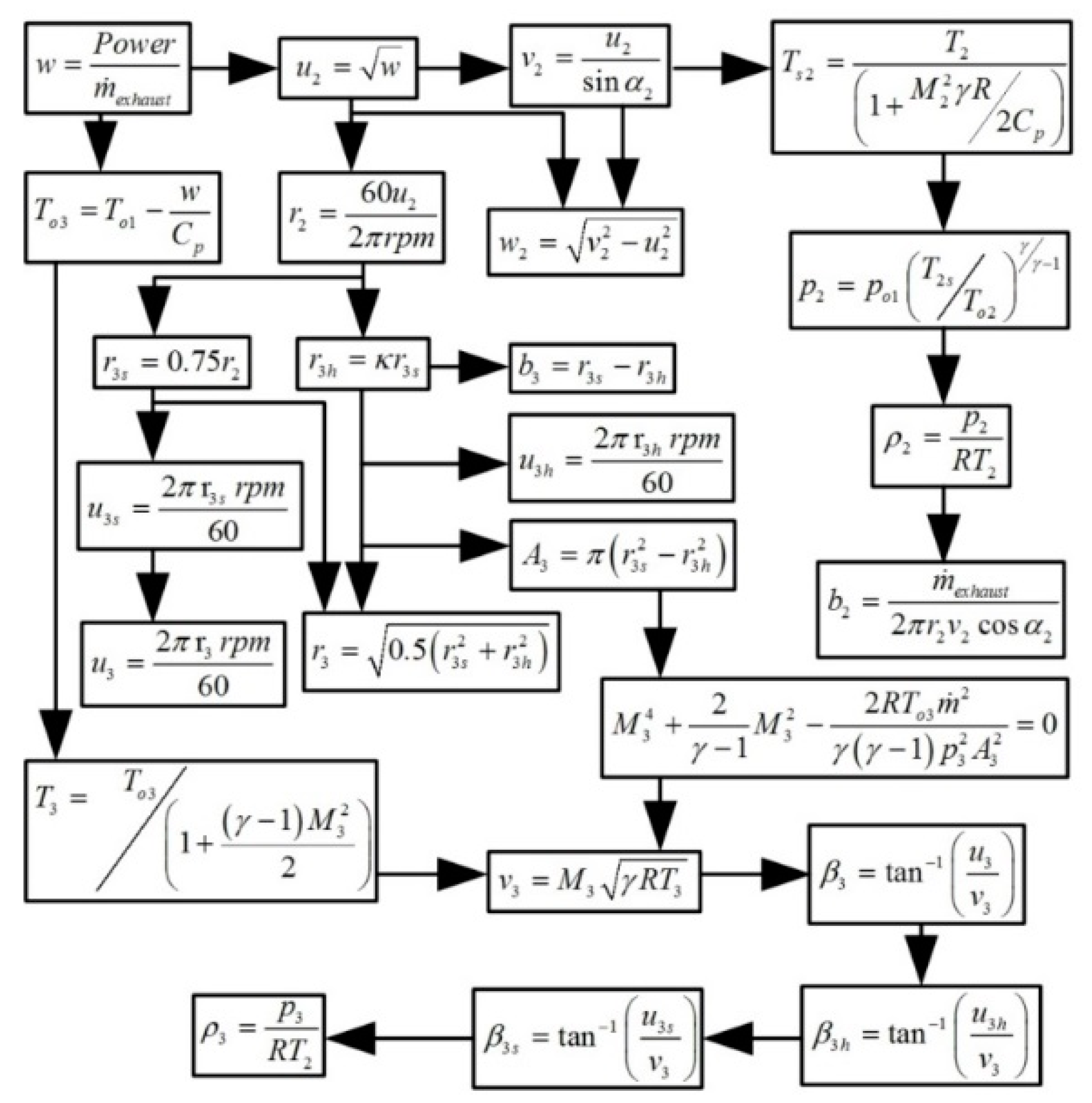
3.2. Flow Chart for Calculating the Exhaust Mass Flow of an Internal Combustion Engine
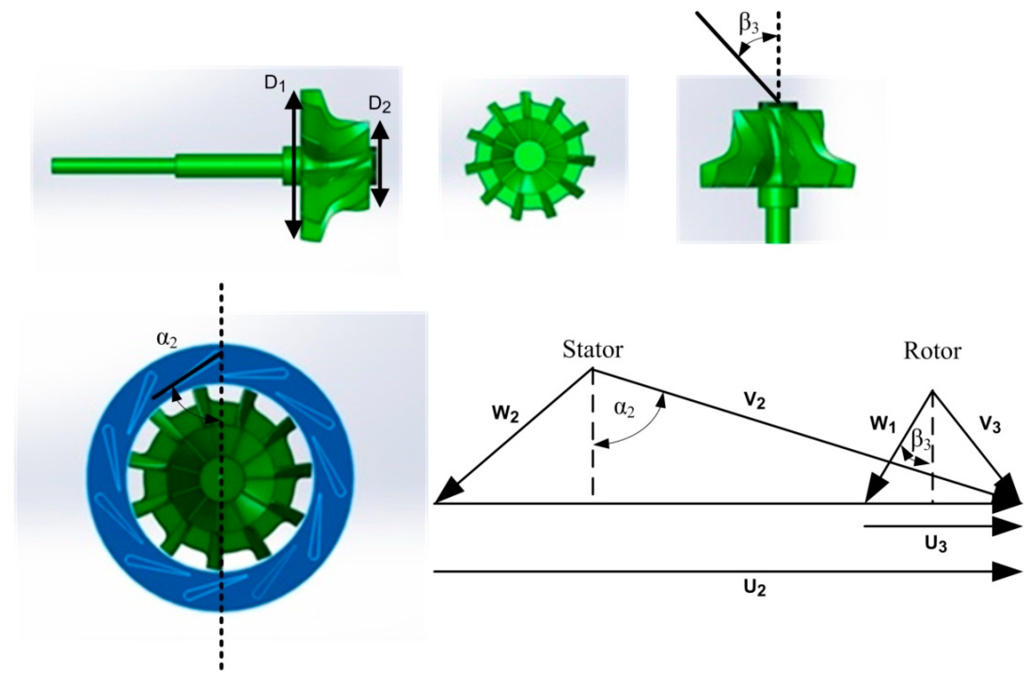
3.3. Specific Design
3.4. Formula for One Dimensional Calculation
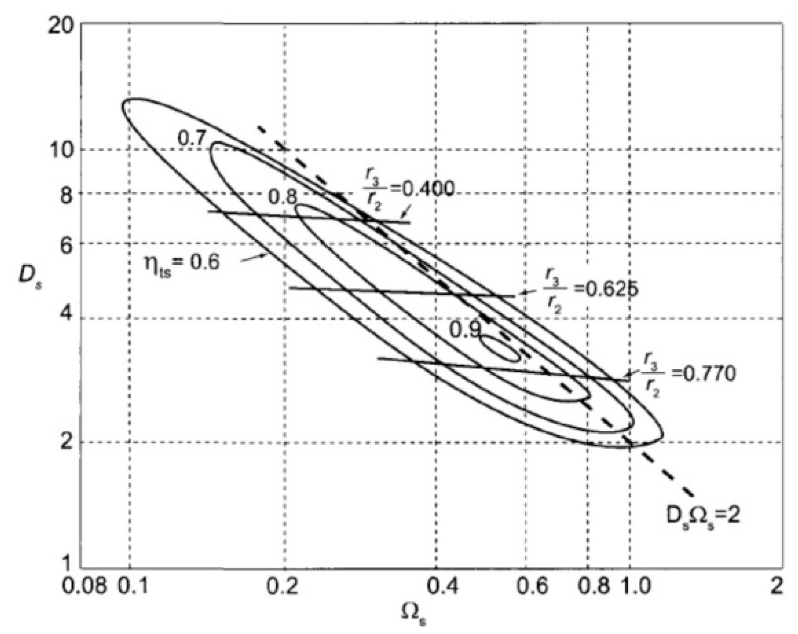
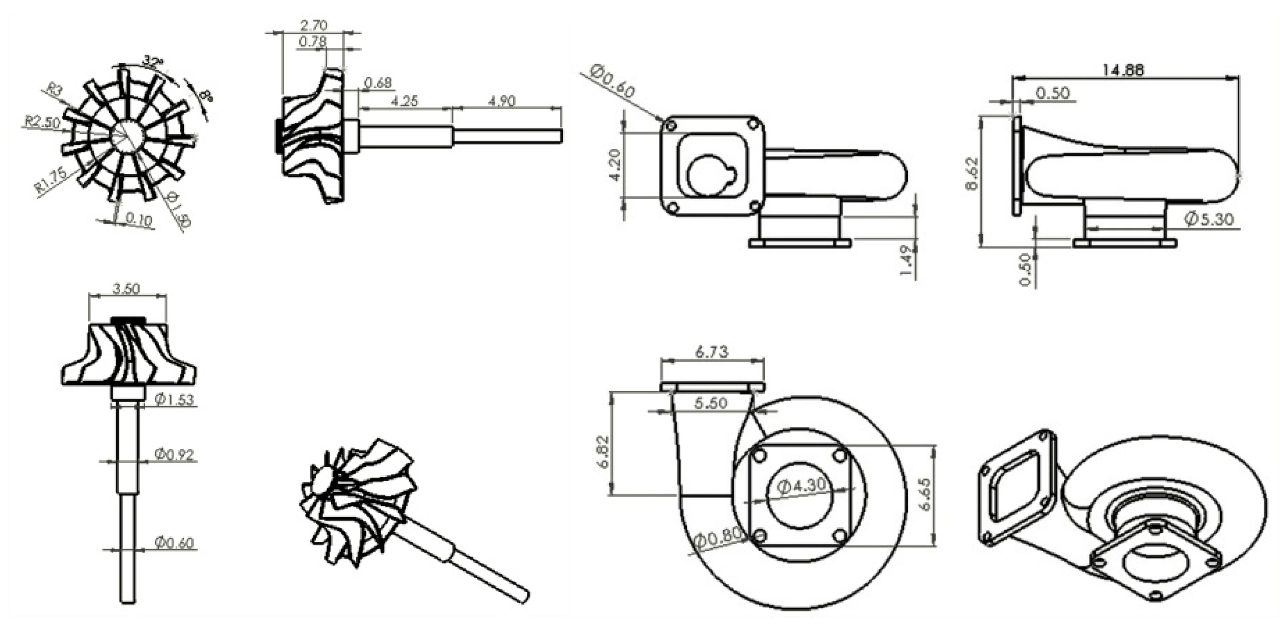
3.5. The Dimension Design
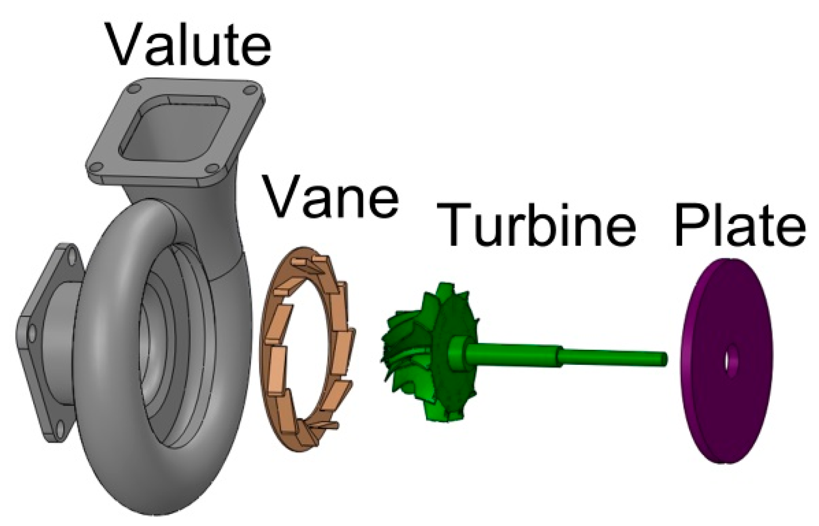
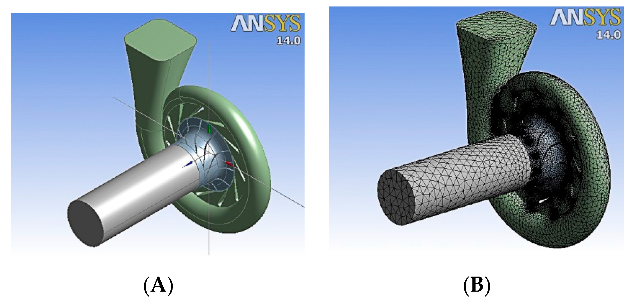
3.6. Drawing the Turbo-Generator
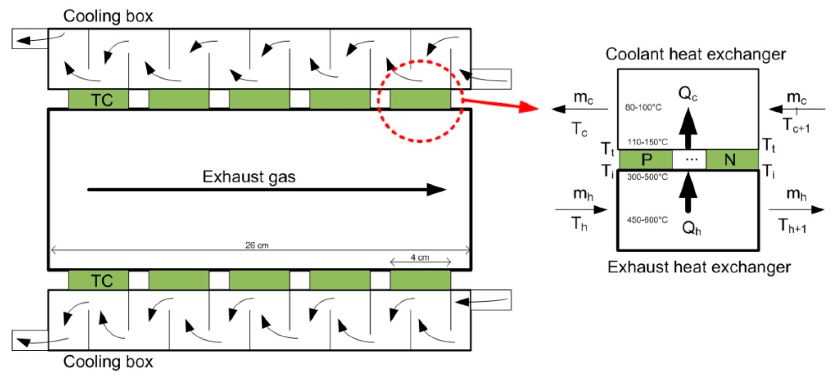
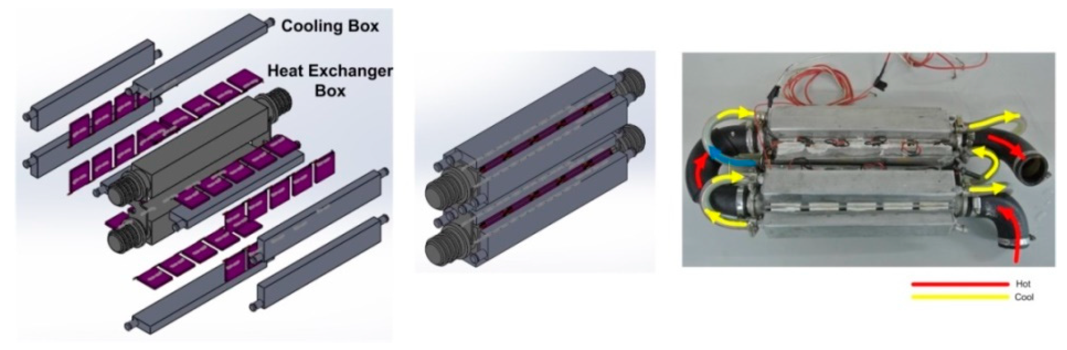
3.7. Drawing and Construction of a Thermoelectric Generator
4. Simulation Results and Optimization
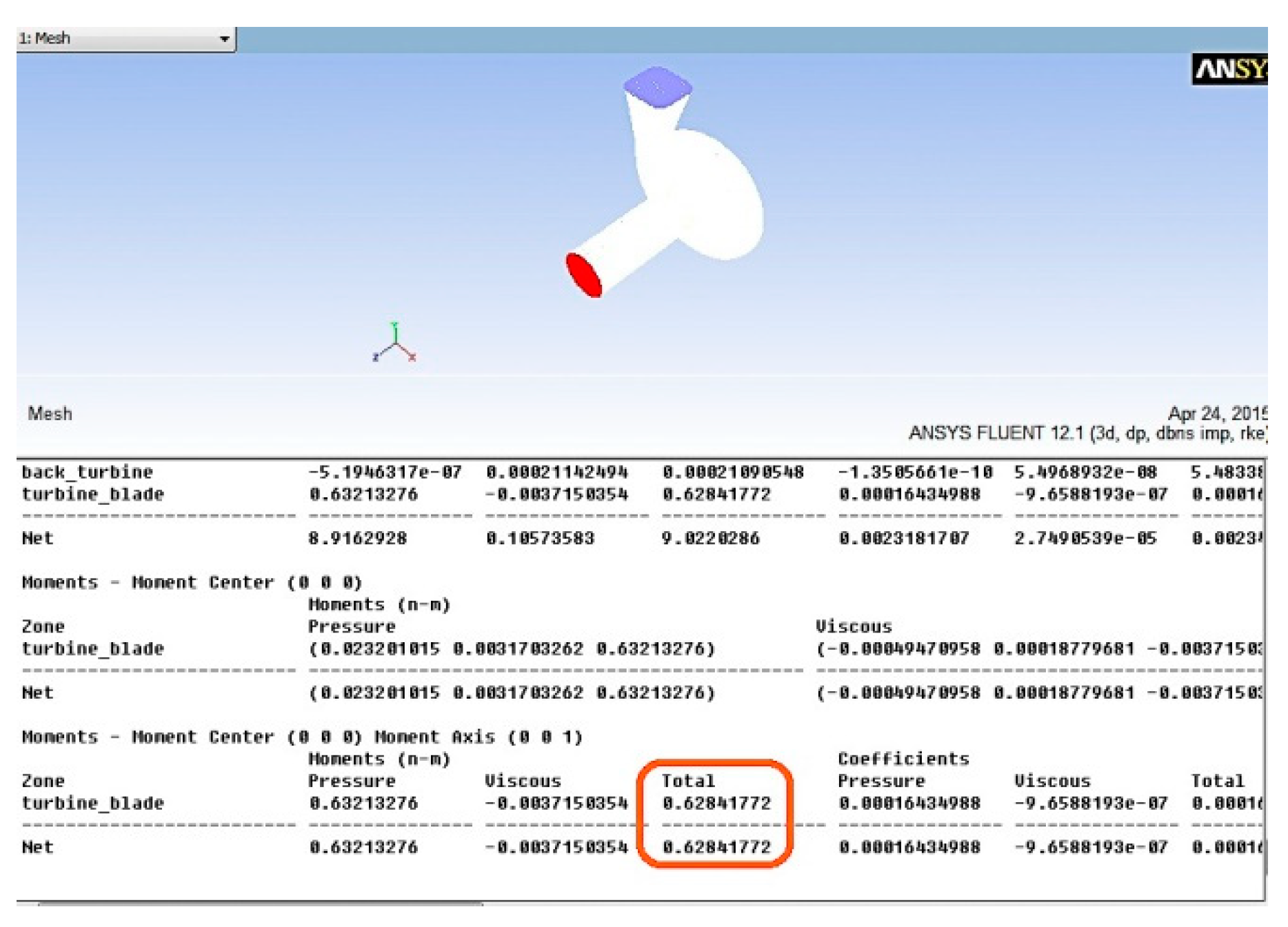
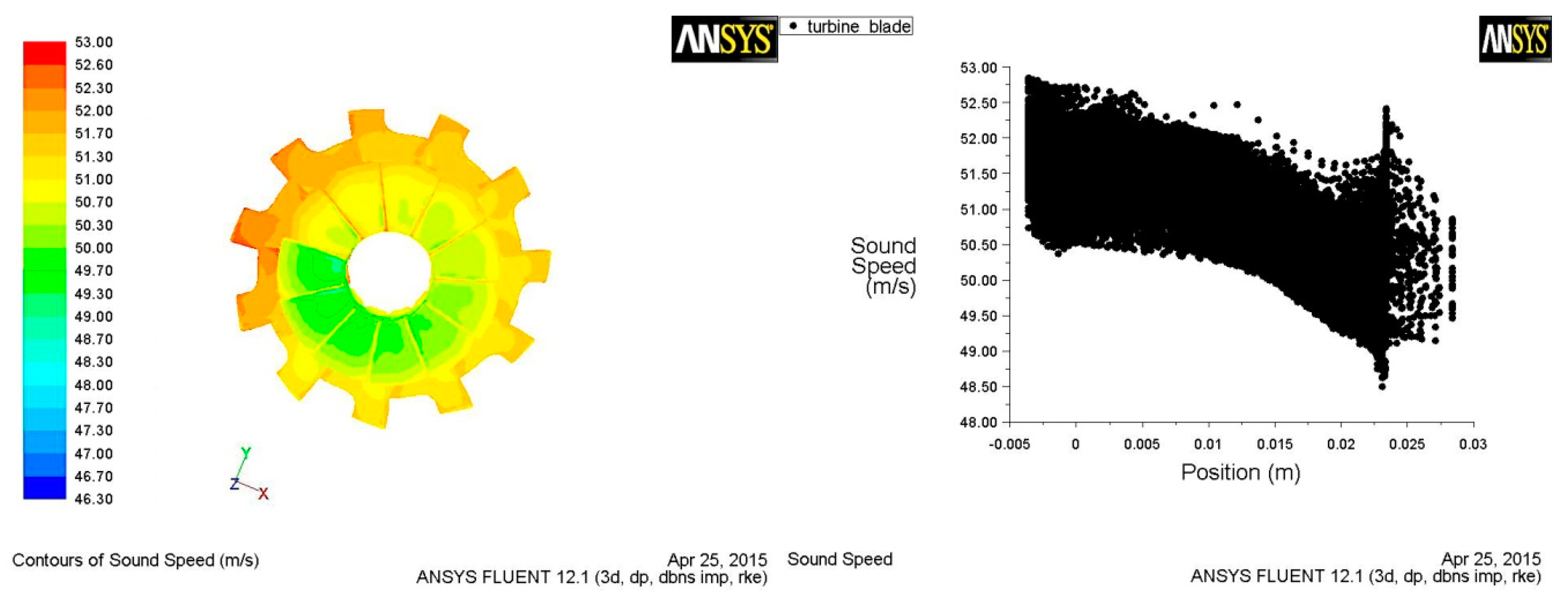
4.1. Turbine Performance
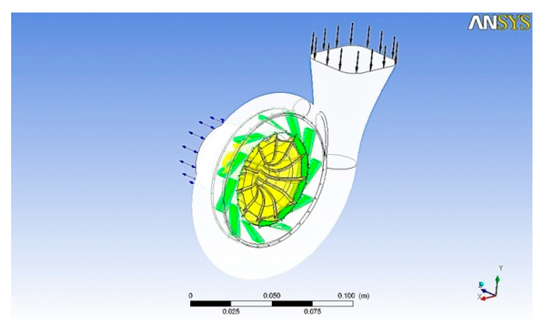
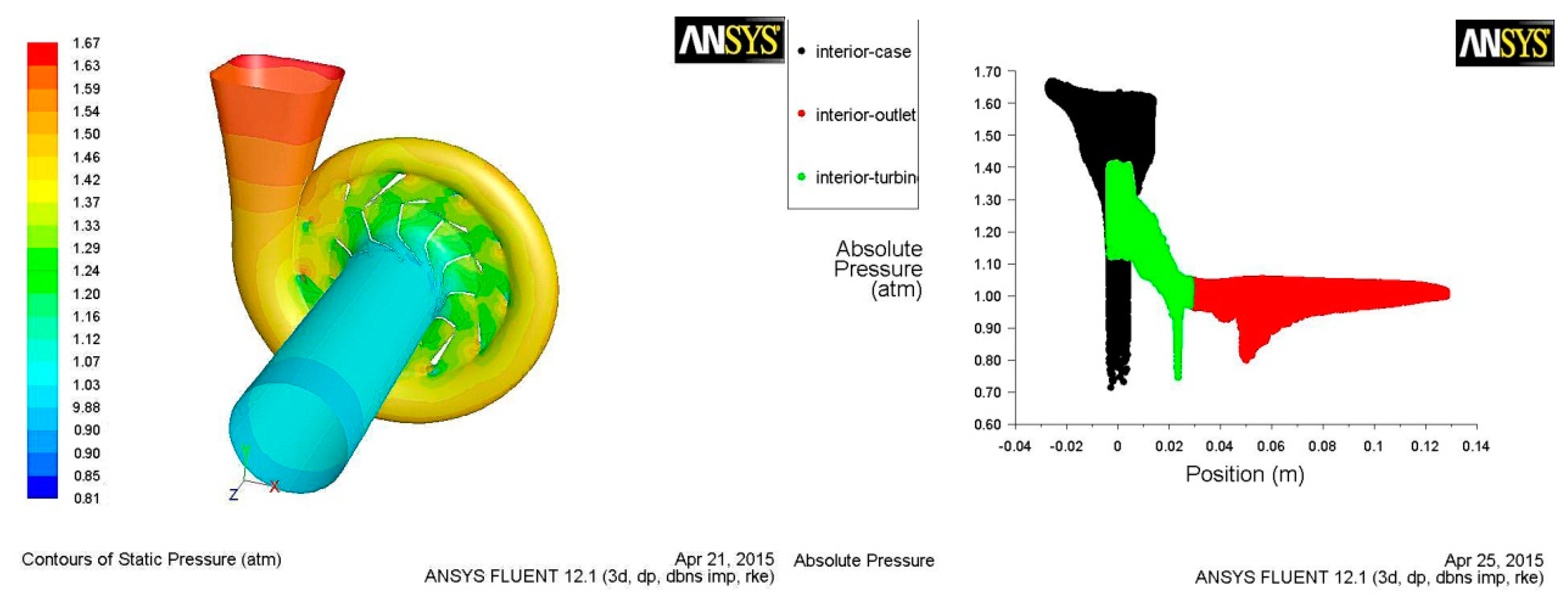
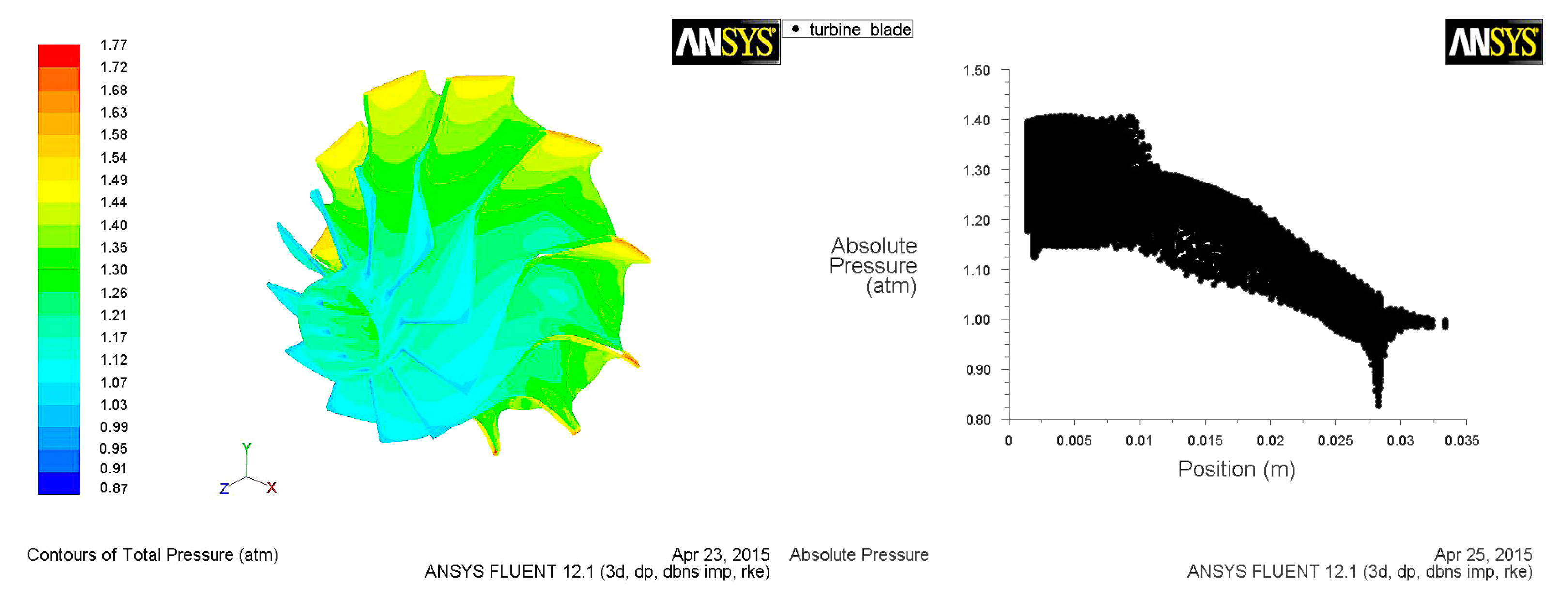
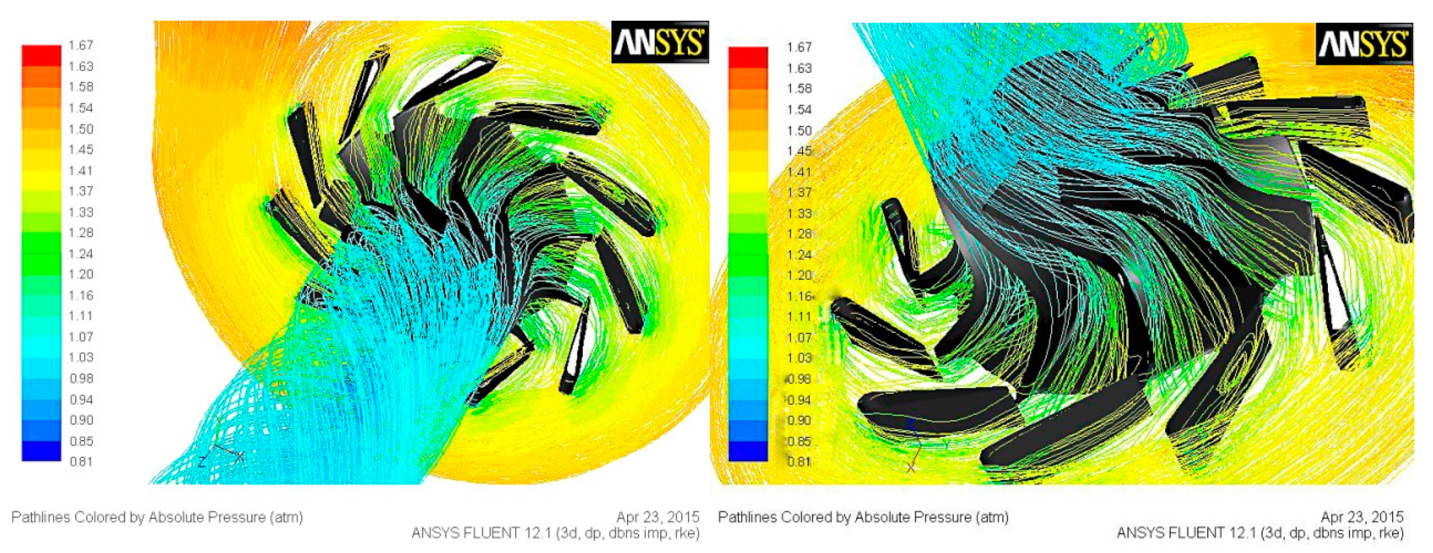
4.2. Pressure and Path Line of Flowing
5. Experimental Results
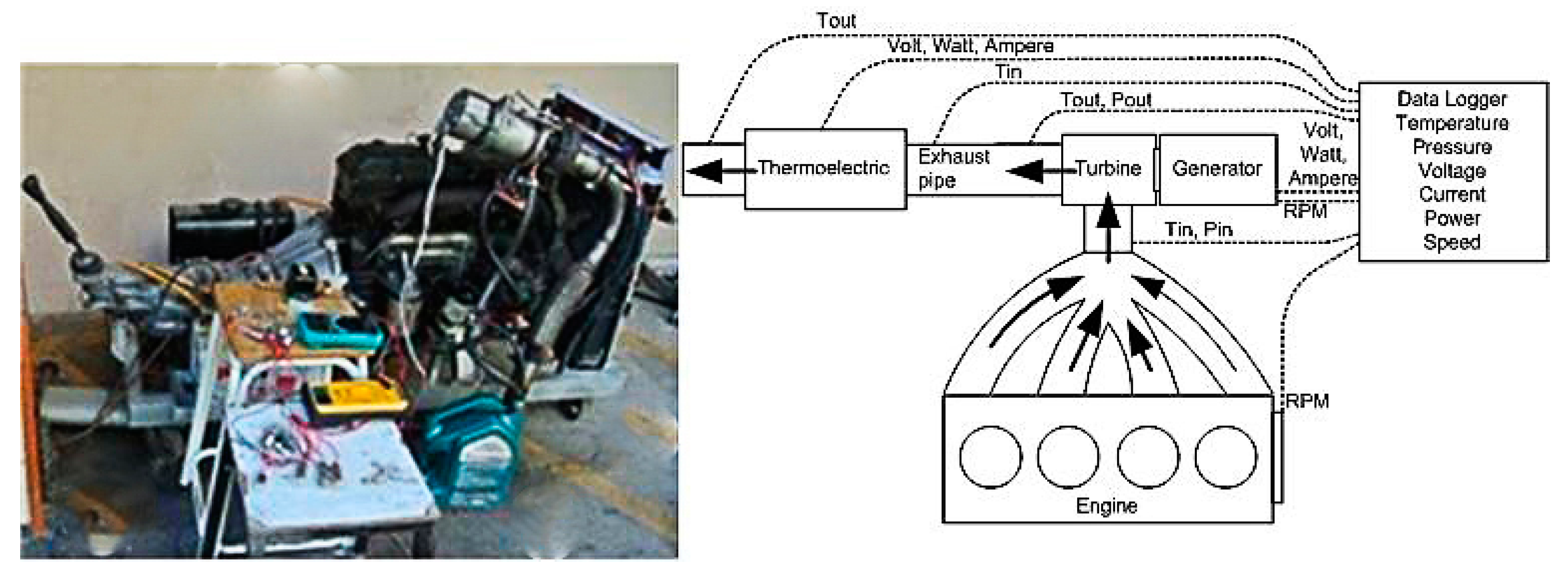
5.1. Experimental Setup
5.2. The Measurement Intrument
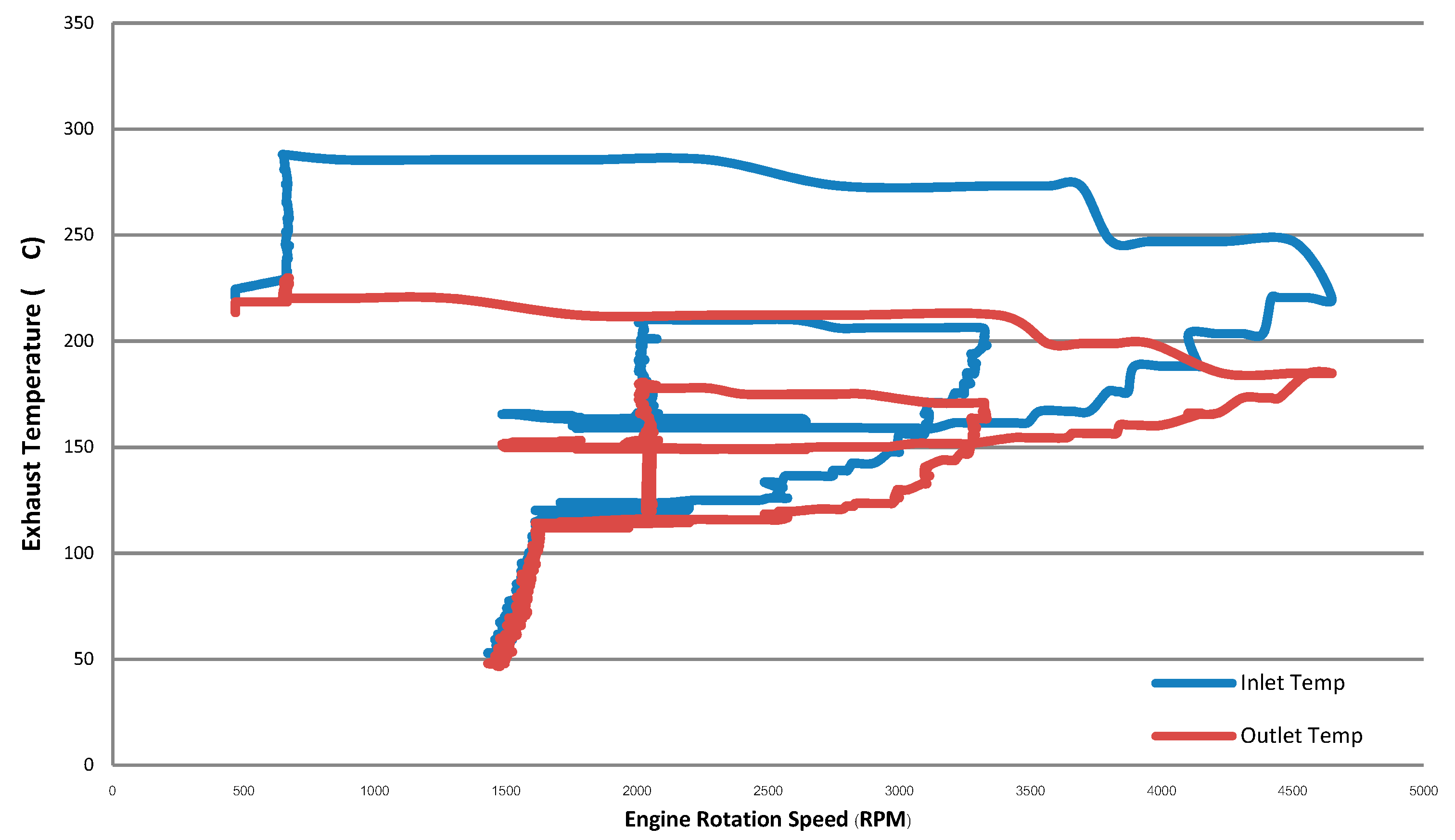
5.3. Temperature of the Exhaust Turbo-Generator
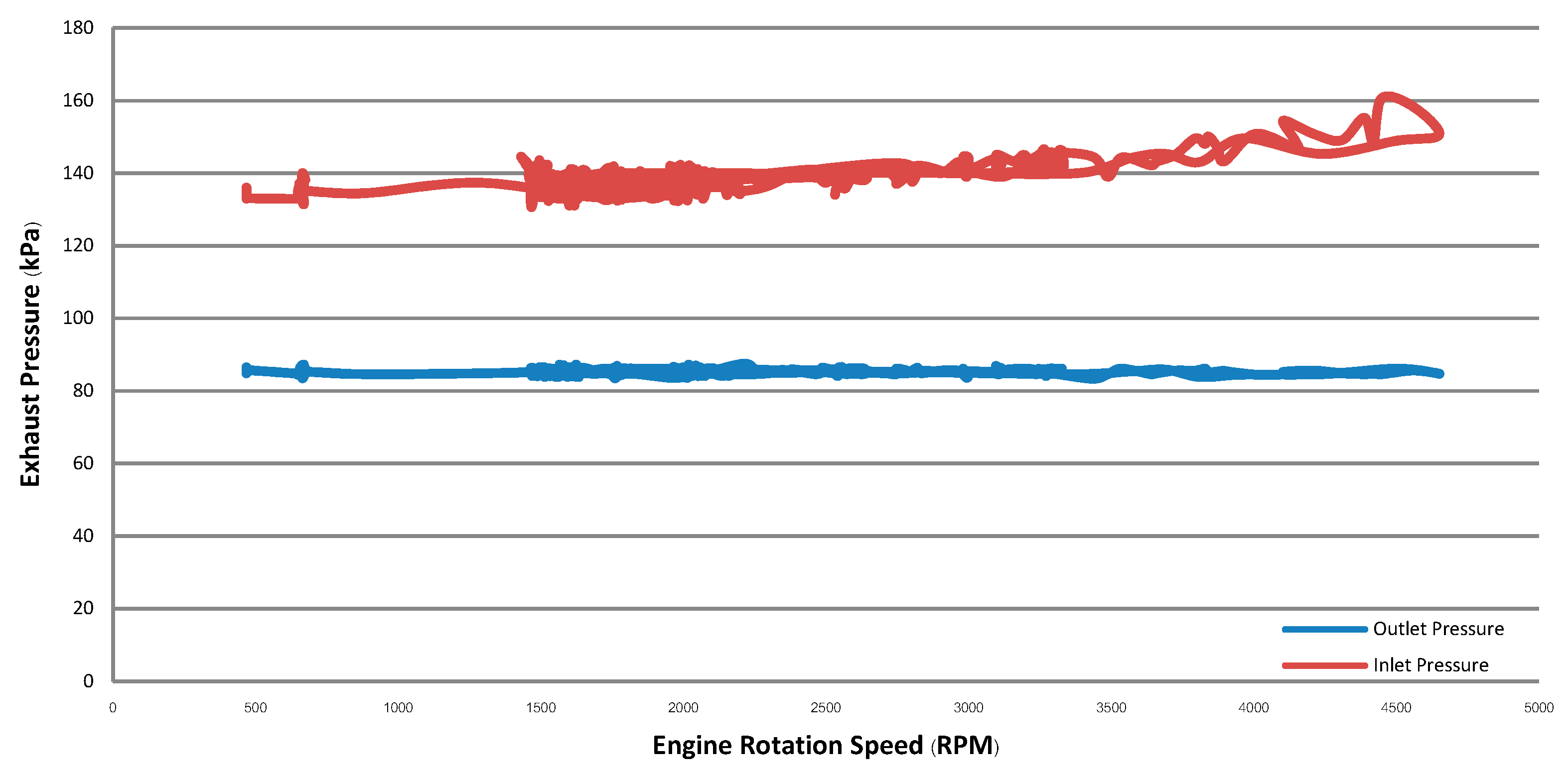
5.4. Pressure of the Exhaust Turbo-Generator
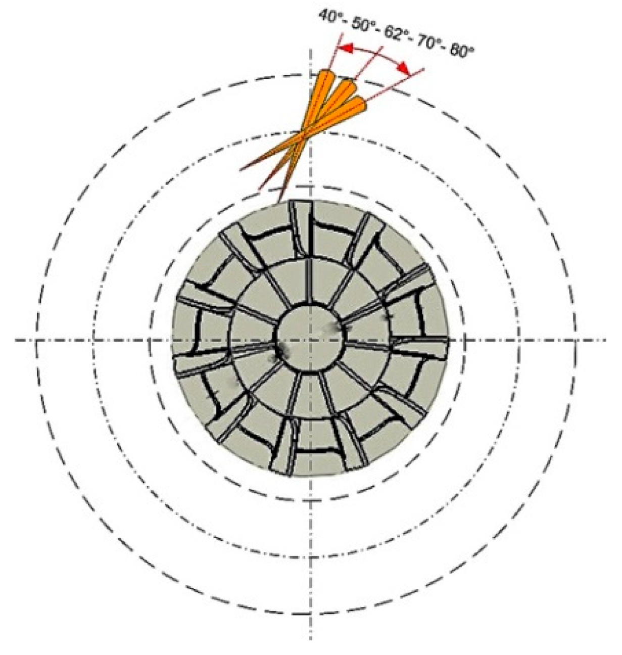
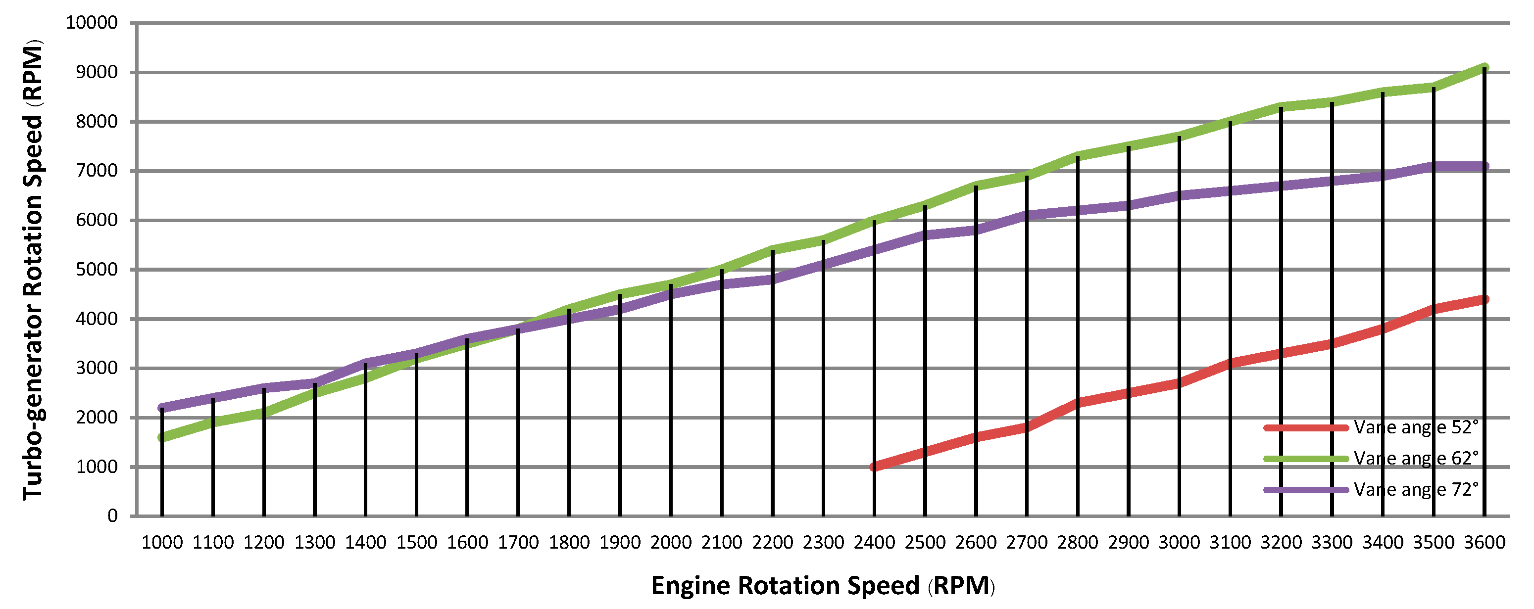
5.5. Rotation Speed of the Turbo-Generator Test Based on a Variable Vane Angle
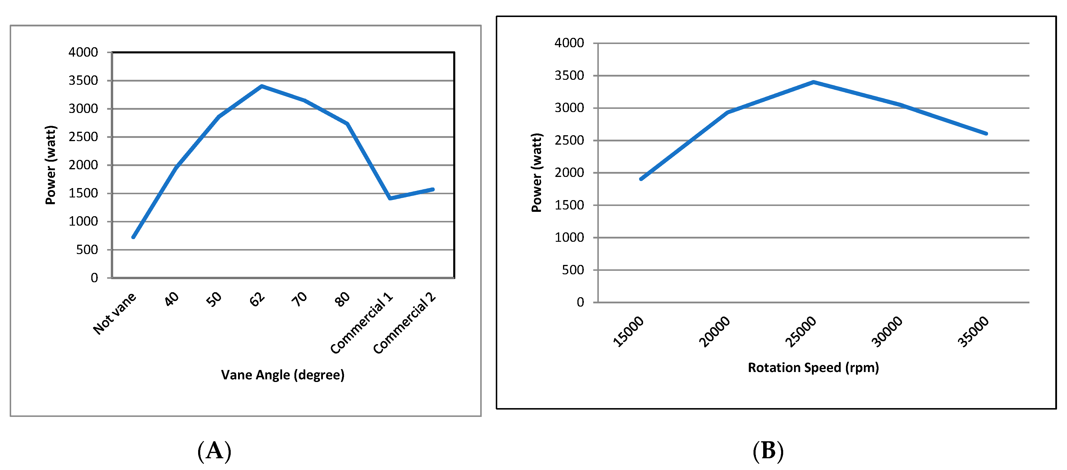
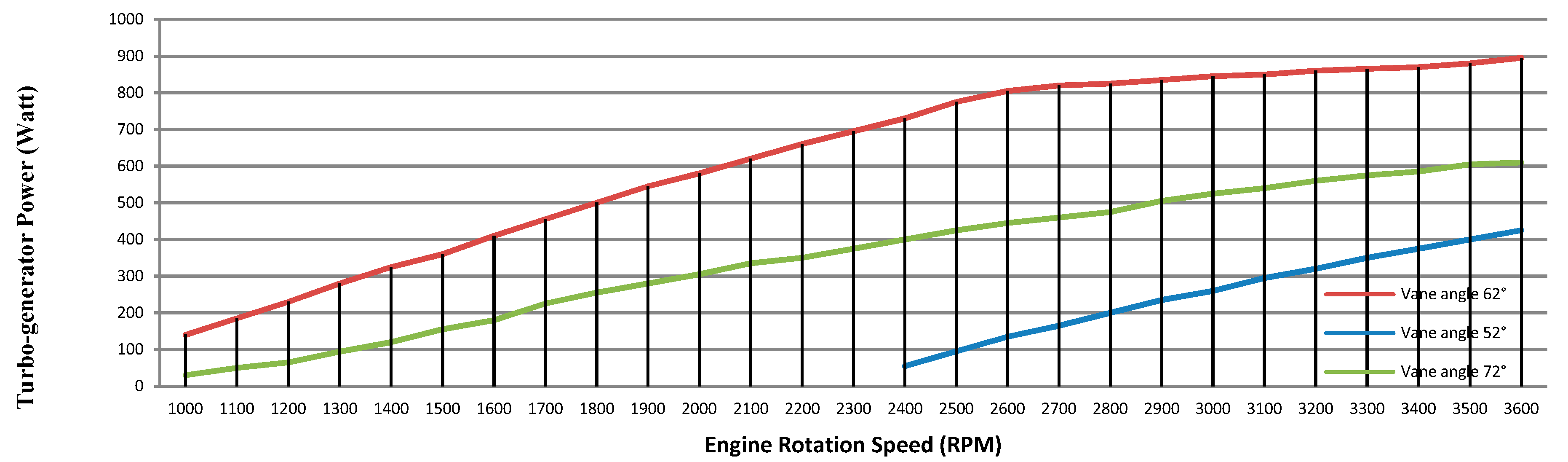
5.6. Power of the Turbo-Generator Test Based on Adjusting the Vane Angle
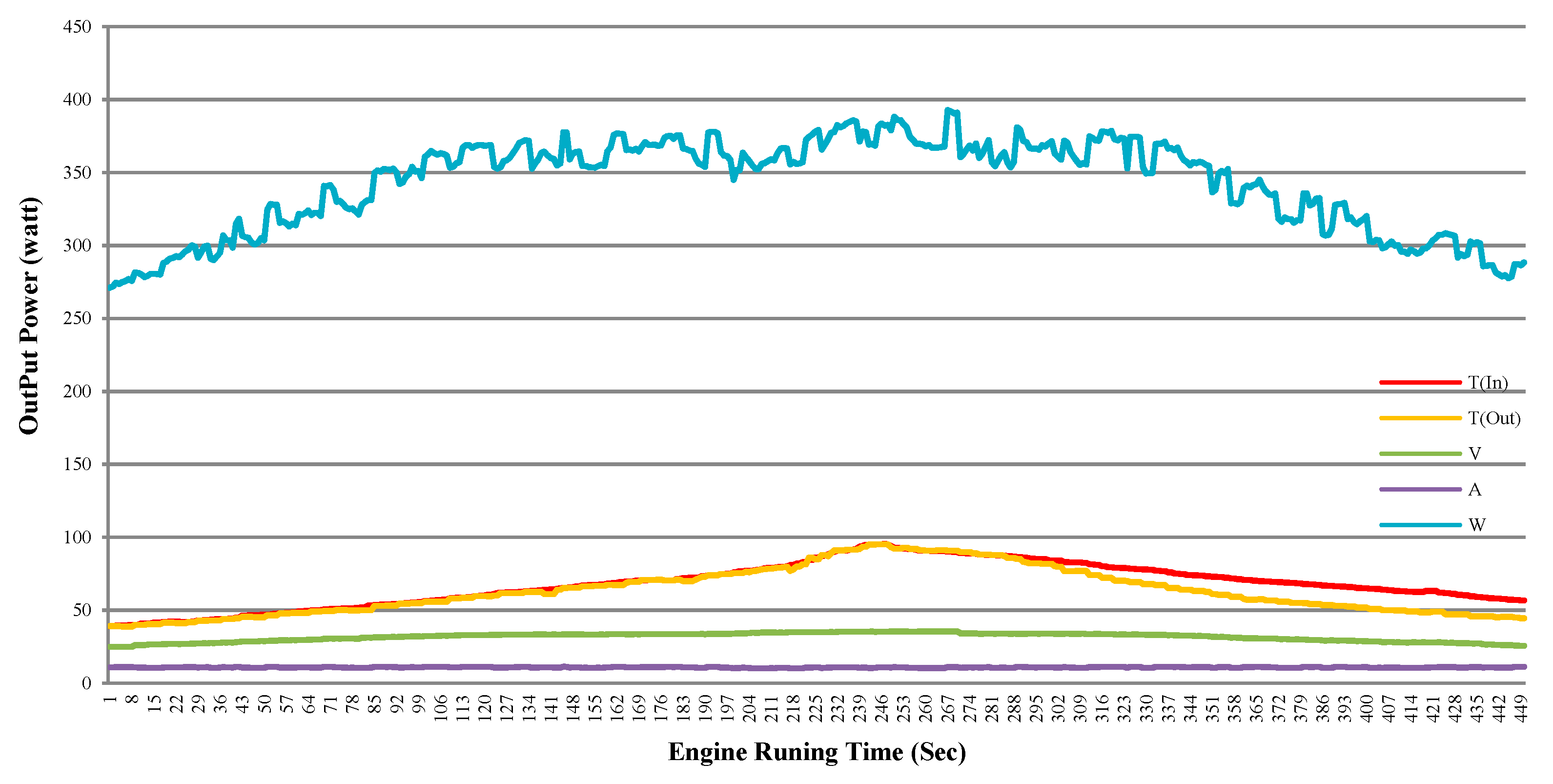
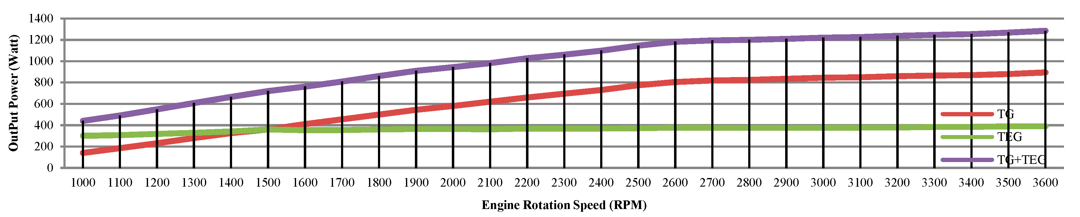
5.7. Power of the Thermoelectric-Generator Test
6. Conclusions
Author Contributions
Funding
Acknowledgments
Conflicts of Interest
References
- Yang, J. Potential applications of thermoelectric waste heat recovery in the automotive industry. In Proceedings of the International Conference on Thermoelectrics, Clemson, SC, USA, 19–23 June 2005; pp. 155–159. [Google Scholar]
- Xiong, Y.; Xu, L.; Zhong, Y. The Theory and Application of Energy-Saving Technology on Vehicle; China Petrochemical Press: Beijing, China, 2006; pp. 9–13. [Google Scholar]
- Fu, J.; Liu, J.; Yang, Y.; Yang, H. A study on the prospect of engine exhaust gas energy recovery. In Proceedings of the International Conference on Electric Information and Control Engineering, Wuhan, China, 15–17 April 2011. [Google Scholar]
- Jorge, V. State of the Art of Thermoelectric Generators Based on Heat Recovered from the Exhaust Gases of Automobiles. In Proceedings of the 7th European Workshop on Thermoelectric, Pamplona, Spain, 3–4 October 2002. [Google Scholar]
- La Grandeur, J.; Doug Crane, D.; Eder, A. Vehicle Fuel Economy Improvement through Thermoelectric Waste Heat Recovery. In Proceedings of the 11th Diesel Engine Emissions Reduction (DEER) Conference, Chicago, IL, USA, 21–25 August 2005. [Google Scholar]
- Fairbanks, J. Overview of High Efficiency Thermoelectric and Potential Applications. In Proceedings of the High Efficiency Thermoelectric Workshop, San Diego, CA, USA, 17–20 February 2004. [Google Scholar]
- Michon, M. Switched Reluctance Turbo-Generator for Exhaust Gas Energy Recovery. In Proceedings of the International Conference on Electric Machines & Drives Conference (IEMDC), Niagara Falls, ON, Canada, 15–18 May 2011; pp. 1609–1614. [Google Scholar]
- Aman Mamat, M.I. Design and Development of a Low Pressure Turbine for Turbocompounding Applications. Int. J. Gas Turbine Propuls. Power Syst. 2012, 4, 1–8. [Google Scholar]
- Hopmann, U.; Algrain, M.C. Diesel Engine Electric Turbo Compound Technology. In Proceedings of the Future Transportation Technology Conference & Exhibition; SAE International: Warrendale, PA, USA, 2003. [Google Scholar] [CrossRef]
- Hopmann, U. Diesel engine waste heat recovery utilizing electric turbocompound technology. In Proceedings of the Catterpillar, DEER Conference, San Diego, CA, USA, 30 August–2 September 2004. [Google Scholar]
- Hopmann, U.; Algrain, M. Diesel engine waste heat recovery utilizing electric turbocompound technology. Presented at the 2003 DEER Conference, Newport, Rhode Island, 25–28 August 2003; Caterpillar Inc.: Deerfield, IL, USA, 2003. [Google Scholar]
- Bowman Power Group Ltd. Available online: http://www.bowmanpower.com/power_generators.php (accessed on 20 August 2017).
- Controlled Power Technologies Limited. Available online: http://www.cpowert.com/products/tigers/ (accessed on 20 August 2017).
- Srinivasan, K.K.; Mago, P.J.; Krishnan, S.R. Analysis of exhaust waste heat recovery from a dual fuel low temperature combustion engine using an Organic Rankine Cycle. Energy 2010, 35, 2387–2399. [Google Scholar] [CrossRef]
- Yamada, N.; Minami, T.; Mohamad, M.N. Fundamental experiment of pumpless Rankine-type cycle for low-temperature heat recovery. Energy 2011, 36, 1010–1017. [Google Scholar] [CrossRef]
- Liu, X.; Deng, Y.D.; Chen, S.; Wang, W.S.; Xu, Y.; Su, C.Q. A case study on compatibility of automotive exhaust thermoelectric generation system, catalytic converter and muffler. Case Stud. Therm. Eng. 2014, 2, 62–66. [Google Scholar] [CrossRef]
- Kim, T.Y.; Negash, A.A.; Cho, G. Waste heat recovery of a diesel engine using a thermoelectric generator equipped with customized thermoelectric modules. Energy Convers. Manag. 2016, 124, 280–286. [Google Scholar] [CrossRef]
- Liang, X.; Sun, X.; Tian, H.; Shu, G.; Wang, Y.; Wang, X. Comparison and parameter optimization of a two-stage thermoelectric generator using high temperature exhaust of internal combustion engine. Appl. Energy 2014, 130, 190–199. [Google Scholar] [CrossRef]
- Tian, H.; Sun, X.; Jia, Q.; Liang, X.; Shu, G.; Wang, X. Comparison and parameter optimization of a segmented thermoelectric generator by using the high temperature exhaust of a diesel engine. Energy 2015, 84, 121–130. [Google Scholar] [CrossRef]
- Temizer, İ.; İlkılı, C. The performance and analysis of the thermoelectric generator system used in diesel engines. Renew. Sustain. Energy Rev. 2016, 63, 141–151. [Google Scholar] [CrossRef]
- Liu, C.; Pan, X.; Zheng, X.; Yan, Y.; Li, W. An experimental study of a novel prototype for two-stage thermoelectric generator from vehicle exhaust. J. Energy Inst. 2016, 89, 271–281. [Google Scholar] [CrossRef]
- Seppo, A. Principles of Turbomachinery; John Wiley & Sons: New York, NY, USA, 2011. [Google Scholar]
- Luft, M.; Olszowiec, P. Losses of IC engine—A chance for electrical energy recuperation. Zesz. Nauk. Akad. Morska Szczec. 2012, 30, 78–82. [Google Scholar]


| Engine | Mobile | Type | Energy Receive | Speed | Weigh Extra | Reference |
|---|---|---|---|---|---|---|
| n/a | Yes (Heavy-Duty) | TG | 600 W | 45,000 rpm | 11 kg | [11] |
| n/a | n/a | TG | 1.8 kW | 80,000 rpm | n/a | [12] |
| Diesel | No (Power Plant) | TG | 30 kW | 60,000 rpm | 50 kg | [13] |
| Gasoline 1.0 L | Yes (Passenger) | TG | 1.0 kW | 50,000 rpm | n/a | [14] |
| Diesel | Yes (Heavy-Duty) | TEG | 119 W | n/a | n/a | [18] |
| Diesel | Yes | TEG | 156.7 W | n/a | n/a | [21] |
| Diesel | No (Power Plant) | TEG | 250W | n/a | n/a | [22] |
| Diesel 2.5 L | Yes (Light-Truck) | TG + TEG | 1262 W | 50,000 rpm | 15 kg | Author work |
| Engine Rotation Speed (rpm) | Exhaust Gas Mass Flow Rate (kg/sec) | Exhaust Gas Flow Velocity (m/min) |
|---|---|---|
| 1000 | 0.0320 | 900 |
| 2000 | 0.0640 | 1799 |
| 3000 | 0.0960 | 2699 |
| 3200 | 0.1024 | 3598 |
| 4000 | 0.1280 | 3778 |
| 5000 | 0.1600 | 4498 |
| Parameter | Recommended Range | Source |
|---|---|---|
| 68–75 | Dixon, Rohlik | |
| 50–70 | Whitfiel and Baines | |
| <0.4 | Dixon, Rohlik | |
| <0.7 | Dixon, Rohlik | |
| 0.53–0.66 | Whitfiel and Baines | |
| 0.05–0.15 | Whitfiel and Baines, Dixon, Rohlik | |
| 0.55–0.80 | Balje diagram | |
| 2–2.5 | Ribaud and Mischell | |
| 0.15–0.5 | Whitfiel and Baines |
| No | Description | Abbreviation | Unit | Value |
|---|---|---|---|---|
| 1 | The flow angle at inlet of impeller | 62 | ||
| 2 | The radius at inlet | 0.0298 | ||
| 3 | The inlet blade height | 0.0076 | ||
| 4 | The rotor shroud radius | 0.0175 | ||
| 5 | The rotor hub radius | 0.0075 | ||
| 6 | The mean exit radius | 0.0134 | ||
| 7 | The flow angle of relative velocity at outlet | 17.4907 | ||
| 8 | The flow angle of relative velocity at shroud | 22.2716 | ||
| 9 | The flow angle of relative velocity at hub | 9.9650 | ||
| 10 | The blade width at outlet | 0.01 |
| Turbine | New Design Rotor | Commercial Rotor1/2 * |
|---|---|---|
| Number of blades | 11 | 11 |
| Inlet blade angle | 62° | 20°/30° |
| Outlet blade angle | 17° | 50°/60° |
| Turbine diameter (mm) | 60 | 60 |
| Vane angle | Varied 62° | No vane |
| Rotation speed (rpm) | 52,000 | |
| Mass flow rate (kg/s) | 0.1024 | |
| Temperature inlet/outlet (°C) | 400/80 | |
| Pressure outlet (bar) | 1.1 | |
| None | 40° | 50° | 62° | 70° | 80° | Commercial 1 | Commercial 2 | |
|---|---|---|---|---|---|---|---|---|
| Torque | 0.138 | 0.355 | 0.525 | 0.624 | 0.578 | 0.502 | 0.259 | 0.289 |
| Power | 752 | 1937 | 2858 | 3401 | 3147 | 2734 | 1411 | 1573 |
© 2019 by the authors. Licensee MDPI, Basel, Switzerland. This article is an open access article distributed under the terms and conditions of the Creative Commons Attribution (CC BY) license (http://creativecommons.org/licenses/by/4.0/).
Share and Cite
Nonthakarn, P.; Ekpanyapong, M.; Nontakaew, U.; Bohez, E. Design and Optimization of an Integrated Turbo-Generator and Thermoelectric Generator for Vehicle Exhaust Electrical Energy Recovery. Energies 2019, 12, 3134. https://doi.org/10.3390/en12163134
Nonthakarn P, Ekpanyapong M, Nontakaew U, Bohez E. Design and Optimization of an Integrated Turbo-Generator and Thermoelectric Generator for Vehicle Exhaust Electrical Energy Recovery. Energies. 2019; 12(16):3134. https://doi.org/10.3390/en12163134
Chicago/Turabian StyleNonthakarn, Prasert, Mongkol Ekpanyapong, Udomkiat Nontakaew, and Erik Bohez. 2019. "Design and Optimization of an Integrated Turbo-Generator and Thermoelectric Generator for Vehicle Exhaust Electrical Energy Recovery" Energies 12, no. 16: 3134. https://doi.org/10.3390/en12163134
APA StyleNonthakarn, P., Ekpanyapong, M., Nontakaew, U., & Bohez, E. (2019). Design and Optimization of an Integrated Turbo-Generator and Thermoelectric Generator for Vehicle Exhaust Electrical Energy Recovery. Energies, 12(16), 3134. https://doi.org/10.3390/en12163134