1. Introduction
One of the methods to reduce the emission of harmful exhaust components emitted by marine combustion engines is to use the waste heat to generate heat energy and electricity. In both cases, the steam produced by the marine exhaust gas boilers (EGB) is utilized. The steam transfers the heat directly through heat exchangers or is a working medium in turbogenerators. It should enable, during a vessel’s travel, to resign from the employment of auxiliary oil-fired boilers and diesel generator units simultaneously limiting the fuel consumption of the marine power systems.
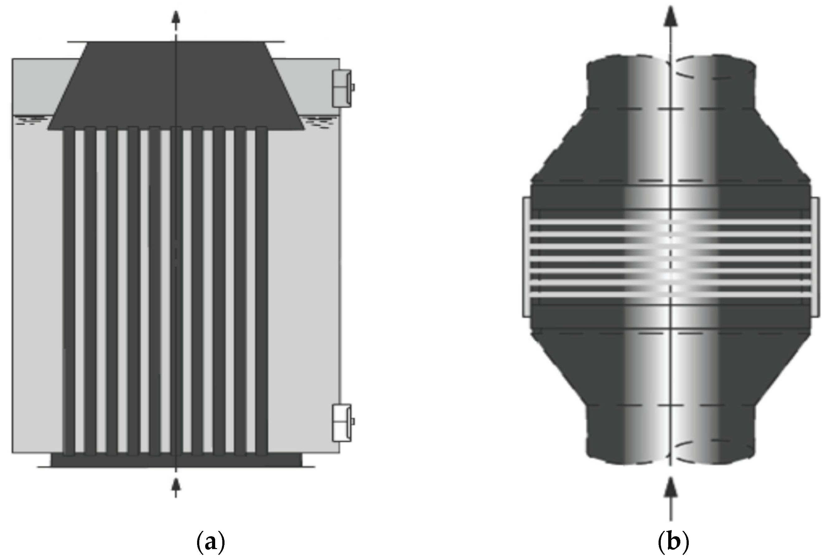
For the majority of the marine power systems, EGB are designed to produce the required amount of steam which would meet the demand for heat for the heating purposes on vessels. The types of EGB may be divided into two main groups: water tube boilers and smoke tube boilers. Their schemes are presented in
Figure 1.
Marine waste heat recovery systems (WHRS) are used more regularly. They are intended and designed to produce the maximum amount of steam in EGBs, essential to meet the demand for heat in the heating systems and electricity. The influence of some methods of using waste heat from exhaust gases and charge air on the amount of steam produced in the EGB are presented in [
2], an integrated modeling framework for the design operation and control of marine energy systems is presented in [
3], and [
4] presents a review on WHRS for internal combustion engines.
A tool necessary to analyze the options resulting in an increase of the amount of the steam produced in an EGB is its mathematical model. Due to the model, it should be possible to determine the amount of generated steam in relation to the exhaust gas volume and its parameters subject to the main engine type and category, power load of the engine, EGB type, its heat, and the distribution of boiler tubes.
The scientific literature provides the methods for determining the amount of heat transferred in the particular EGB sections in the form of theoretical and practical considerations. In [
5] problems of performance of a WHRS power generation system based on second law analysis at various operating conditions were addressed. The effect of pinch point on the performance of the EGB and on the entropy generation rate and second law efficiency are also investigated [
6] describes heat recovery systems in various industries, and [
7] presents sophisticated mathematical methods describing heat exchange processes taking into consideration the float of the liquid and its steam of the liquid and gas taking place in many technical devices and systems in the energetics [
8] provides a theoretical analysis of the influence of the pinch point on the amount of steam produced in a three pressure waste heat recovery system (WHRS), and earlier studies on heat transfer in EGBs were presented in [
9,
10] and as a practical solution using the empirical solutions developed by the boilers’ producers Babcock and Wilcox and the McDermott Company [
11,
12]. Additionally, general information on the proprietary methodology for determining the amount of steam produced by marine exhaust gas boilers has been developed and made available in the literature, and the theoretical basis of vessel waste boiler designs were presented in [
13,
14]. In [
15] the possibility of the steam production increase in the smoke tube EGB under the condition of low load of the electronically-controlled low-speed marine main engines was assessed and in [
16], on the basis of the operation parameters of contemporary container ships, an attempt was made to select EGB capacity in the preliminary design stage, taking into consideration operation conditions of the propulsion system-steam installations unit with respect to EGB reliability.
The analysis of the literature revealed that the materials included therein concern mainly thermodynamic processes, general principles, and formulas used to design EGB waste boilers or to analyze the amount of steam produced in waste boilers used in selected types of ships and for the particular power load conditions of the main drive engine.
Professional experience of the authors, who also work as officer mechanics on the marine ships, as well as in-depth knowledge about the problems of determining the amount of the steam produced by EGBs on different types of ships during the research, have been realized in cooperation with Szczecin Shipyard (exemplary methodologies and studies’ results for waste boilers cooperating with medium-speed engines have been shown in [
16,
17], and with low-speed engines in [
18,
19,
20]), allowed addressing the problem of developing a universal mathematical model describing how EGBs work. This is the first time, unprecedented in the literature, that such a universal mathematical model has been examined.
In view of the practicality of the software as a tool used to determine the amount of steam produced in said boilers, in particular during an analysis of the WHRS in the marine energetic systems, in this article we presented a computer program which includes the mathematical model of the waste boiler.
The developed model refers to EGBs with smooth tubes producing saturated steam which is regularly used for heating purposes and increasingly to feed turbogenerators. It also considers the EGB type (water tube boiler and smoke tube boiler) and the arrangement of the EGB tubes (serial or adjustable).
Additionally, it is possible to establish the EGB dimension, to calculate the resistance of exhaust gas flow through the EGB, to enter the boundary conditions such as the minimum temperature of exhaust gas after the EGB and length of the EGB tubes, and the number of boiler tube stacks.
The reliability of the obtained results has been revised by using the results of the operational measurements made of real objects.
2. Model
The presented mathematical model has been developed based on the analysis of the literature referring to the heat exchange process between the exhaust gas and water in the EGB evaporator section, rules and requirements for designing boilers, algorithms and data structures, and programming techniques.
The amount of energy transferred in the EGB via a medium absorbing the heat [
2,
4,
6,
13] such as water, the mixture of water and steam may be established by using the following Equation (1):
where
QKU is the the amount of energy absorbed in the EGB;
FKU is the heat transfer surface area in the boiler;
kKU is the heat transfer coefficient; and
δt is the logarithmic mean temperature difference.
The amount of energy transferred in the EGB via a medium absorbing the heat [
2,
4,
6,
13]:
where
α1 is the coefficient of heat transfer from the exhaust gas to the shell plate;
α2 is the coefficient of heat transfer from the shell plate to the medium;
λ is the thermal conductivity; and d is the shell plate thickness.
Coefficient α
1 presented in Equation (2) specifies the relation in Equation (3):
where:
α1K is the amount of heat penetration by convection;
αPR is the the amount of heat penetration by means of exhaust gas radiation; and
ξ is the tube perfusion coefficient for exhaust gas boilers,
ξ = 0.90–0.95 [
11,
12,
13,
14].
Exhaust gas radiation is minimal for EGBs fed by marine engine exhaust gas. Therefore, the coefficient
αPR is omitted during the calculations of energy exchange in EGB [
11,
12,
14].
Expression
occurring in the denominator of Equation (2) may be developed to the form as presented in Equation (4):
where
dż is the thickness of the soot layer on the tubes;
dr is the wall thickness of the tubes and
do is the thickness of boiler scale deposits;
λż is the soot thermal conductivity,
λr is the thermal conductivity for tubes’ material and
λo is the thermal conductivity for boiler scale.
Value
, as minimal, is not considered during the calculations [
11,
12,
14]. Another simplification that may be applied is omitting the value
(assuming that the chemical control of water and its treatment being a standard procedure in shipbuilding do not allow for sediment formation).
Value
is replaced by contamination factor
ε. The factor depends on the combusted fuel type, tube arrangement, and the type of heat exchanger. Its value for heat exchangers being elements of EGBs equals
ε = 0.005–0.01 m
2/W [
11,
12,
13,
14].
Since the boiling water coefficient α
2 reaches the value of 11,600 W/m
2K, Equation (2) may be additionally simplified by component
, the value of which, in the case of calculating for the EGB evaporation section, is omitted [
11,
12,
13,
14,
21]. This means that Equation (2) shall be Equation (5):
Given the EGB operation terms and conditions regarding regular cleaning on the exhaust gas part, it may be assumed that contamination factor included in Equation (5) is equal to zero. The above considerations prove that heat transfer coefficient k is decisively affected by the coefficient of heat transfer α1 from the exhaust gas to the shell plate. The coefficient depends mainly on the tubes’ geometric layout in the boiler and their diameter, as well as on the velocity of exhaust gas flow and its physical parameters.
The relation specifying coefficient
α1, determined experimentally, published by the boilers’ producer [
11,
12] is presented by an empirical relation shown in Equation (6):
where
cSP is the specific heat of the exhaust gas and
λ is the thermal conductivity of the tubes’ material;
m&
SP is the mass flow rate for exhaust gases;
νSP is the kinematic viscosity of exhaust gases; and ϕ is the inner diameter of tubes.
Equation (6) refers to a single boiler tube. However, if applied to make calculations for an actual EGB, an additional adjustment should be included. The adjustment value depends on the transverse spacing and longitudinal spacing of the tubes. The methodology for determining the adjustment has been published by the company, as well [
11,
12].
Due to the variations of the amount and temperature of the exhaust gas flowing through the EGB, the work parameters of the exhaust gas boiler may be determined precisely only based on the similitude theory (model theory) including the characteristic numbers (the Nusselt number,
Nu, the Reynolds number, Re, and the Prandtl number,
Pr) [
5,
7,
22].
The basic relation between the Nusselt number and the Reynolds number is presented by Equation (7):
Since the Nusselt number is also described by
, and the Reynolds number by
, Equation (7) may be simplified as follows:
where
α is the heat transfer coefficient;
A,
n are the constants dependent on the flow type and geometry of the heat exchange surface;
λ is the thermal conductivity of the heat medium;
ν is the kinematic viscosity of exhaust gases;
d is the tube diameter; and
w is the medium flow velocity.
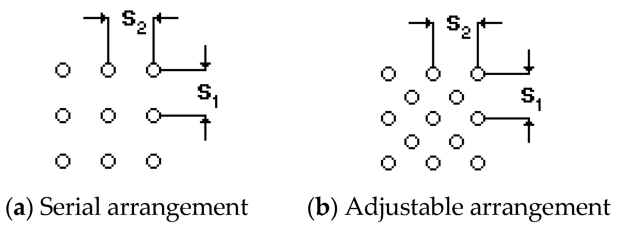
The coefficient of heat transfer in an EGB is significantly affected by the geometric arrangement of the tubes. The main two methods for arranging tubes in the boilers are presented in
Figure 2.
The experimental research performed by Isaczenka [
7,
11,
12] led to determining the average heat transfer coefficient for a tube stack. Upon having included the coefficients which specify an impact of the heat exchanger geometry and the Prandtl number characterizing the medium in the system subject to study, Equation (8) is as shown in Equation (9):
where
Nup is the Nusselt number for a medium perfusing the tube layer;
Rep is the Reynolds number for a medium perfusing the tube layer;
Prp is the Prandtl number for medium stream; and
Prs is he Prandtl number for the medium by the tube wall.
For adjustable arrangement:
Equation (9) is true for the flows described by the numbers
Rep = 10
3–10
5 and
Prp = 0.7–480 while the research conducted by Michiejew [
7,
13,
14] led to the development of the formulas which may be applicable in the wider range of Reynolds numbers:
For serial arrangement:
For adjustable arrangement:
An averaged heat transfer coefficient
α, including average values of coefficients
α in all tube stacks
n and the heat transfer surface area
Ai (m
2) for each stack, may be determined based on Equation (10):
Since, for the EGB producing saturated steam, it may be assumed that all tubes’ stacks are identical in terms of the number and dimensions, Equation (10) may be simplified to Equation (11):
Due to the significant viscosity of exhaust gas flow (
w = 10–15 m/s), it may be assumed that the Reynolds number, which characterizes the exhaust gas flow in the EGB, will equal to
Re > 10
3 [
7,
13,
22]. By implementing the above, the options subject to the analysis may be limited while carrying out calculations or performing simulations of the boiler operation.
The EGB may be constructed of gilled tubes which are used to increase the heat exchange surface. However, nowadays this solution is abandoned due to a large number of fires in boilers with gilled tubes [
1]. Therefore, the consideration of heat exchange coefficients has been discontinued for fin tubes.
The amount of heat energy
QKU absorbed in EGB by heating medium may also be determined by Equation (12):
where
DKU is the mass load of steam flow;
i1 is the enthalpy of water at the inlet to the boiler and
i2 is the enthalpy of water at the outlet from the boiler.
Equation (12) may be solved only by using tables including information on water and water steam enthalpy values as the function of temperature and pressure.
There are equations available approximating the course of selected water and steam parameters that may be applied to develop a mathematical model for EGBs.
The water enthalpy, at various pressure and temperature, may be determined based on empirical Equation (13) [
23]:
where
p is the water pressure;
t is the water temperature;
;
;
; and
.
The values of coefficients in Equation (13) are presented in
Table 1.
Equation (13) enables approximating the table data of water specific enthalpy in the pressure range up to 50 MPa and the temperature range from 0 to 320 °C with an error less than 0.3 kJ/kg [
23].
Equations (14) and (15), developed under [
21,
23], enable determining the value of enthalpy of saturated steam for a pressure range from 0.1 to 2.6 MPa with relative error up to 0.2% and the temperature value
tS of saturated steam for a pressure range from 0.1 to 2.6 MPa with relative error up to 1.64%:
The following equation enabling to determine the amount of heat recovered in EGB Q
KU is Equation (16) [
13,
24]:
where
m&
SP is the mass load of exhaust gas flow through the boiler;
T1,
T2 are the exhaust gas temperatures; 1, inlet, and 2, outlet; and c
1, c
2 are the exhaust gas specific heats; 1, inlet, and 2, outlet.
From Equations (1), (12) and (16) a system of equations arises (Equation (17)) which establishes the amount of steam produced in an EGB in relation to its working conditions:
By developing an individual system of equations (Equation (17)) it is possible to determine the amount of steam produced in the exhaust gas boiler depending on the vessel operating conditions and ambient parameters. Assuming, for an already designed boiler, its efficiency is sought as the function of the amount and temperature of the inlet exhaust gas, resolving the above system of equations is not feasible.
Therefore, based on Equations (1)–(17), one has developed an algorithm using the least squares method [
6,
23], in order to limit errors of calculations and enable carrying out the calculations of the amount of produced steam and the temperature of exhaust gas after the boiler.
The calculations are made based on the following work parameters of the exhaust gas boiler where: pKU is the boiler working pressure and tWZ is the temperature of boiler feed water; ε is the coefficient of the tubes’ contamination; m&SP is the mass load of the exhaust gas flow through the boiler; and tSP is the exhaust gas temperature at the inlet to the boiler.
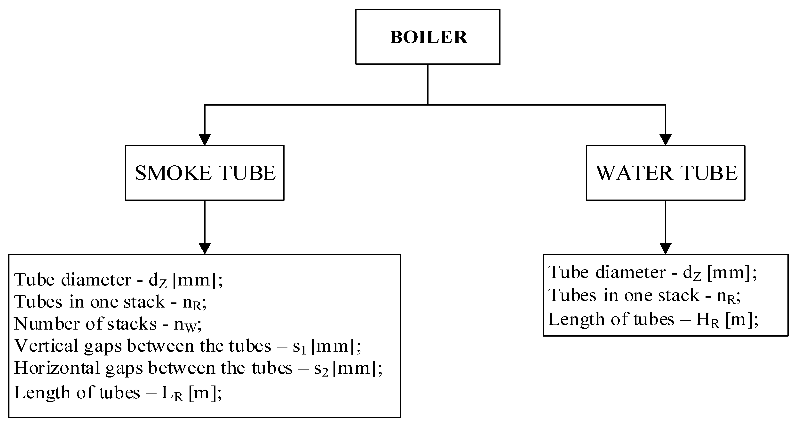
Moreover, the basic structural parameters of the EGB subject to research (smoke tube boilers and water tube boilers) should be determined under to the algorithm presented in
Figure 3.
The values characterizing the work parameters of the EGB, i.e., pKU, tWZ, and its dimensions dz, s1 s2, nw, nr, LR, and HR are provided by the technical documentation of the boiler. The parameters of the main engine exhaust gas feeding the boiler are determined based on the calculation procedures or due to measurements carried out directly.
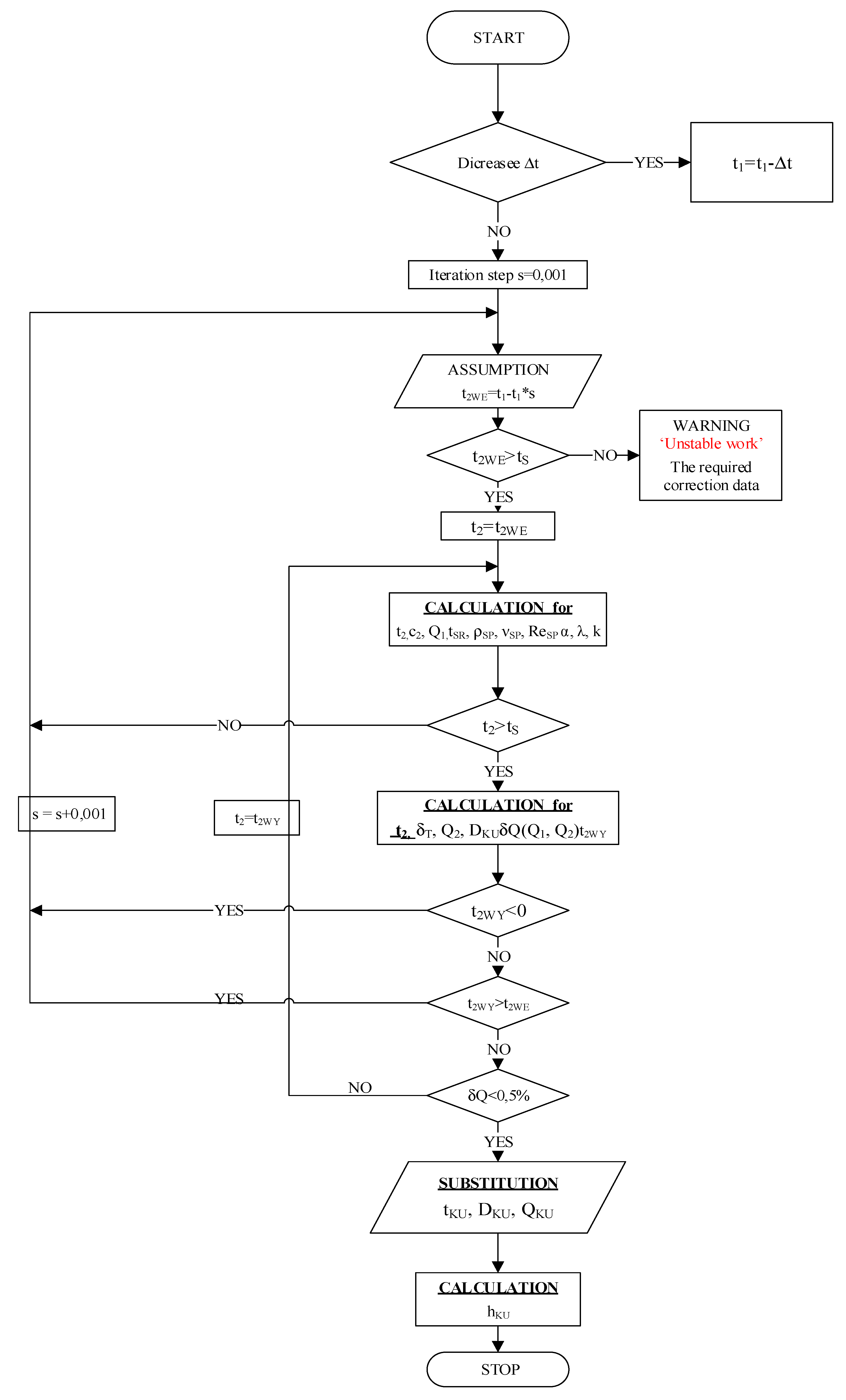
Based on the previously presented relations which describe the energy exchange processes in EGB and using the results of initial simulations, an algorithm has been developed. It enables to determine the work parameters of single-pressure waste heat boilers producing dry saturated steam (the amount of generated steam (kg/h), exhaust gas temperature after the EGB (°C), the amount of heat recovered in the EGB (kW)). The algorithm is presented in
Figure 4.
The symbols adopted and used in the algorithm are as follows:
s is iteration step in a calculation loop, Δt represents the exhaust gas temperature decrease between the turbocharger and the boiler, tSR is the average temperature of exhaust gas flowing through the boiler, t2WE is the temperature of exhaust gas after the boiler at the inlet to the calculation loop, t2WY is the temperature of exhaust gas after the boiler at the outlet to the calculation loop, Q1 is the heat recovered in the boiler during steam production at the inlet to the calculation loop, Q2 is the heat recovered in the boiler during steam production at the outlet to the calculation loop, QKU is the heat recovered in the boiler during steam production, δQ is the relative calculation error of the heat recovered in the boiler, ρSP is the density of exhaust gas flowing through the boiler, νSP is the kinematic viscosity of exhaust gas flowing through the boiler, ReSP is the Reynolds number for the exhaust gas flowing through the boiler, and hKU is the resistance of the exhaust gas flow through the boiler.
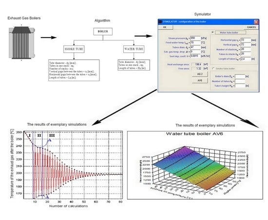
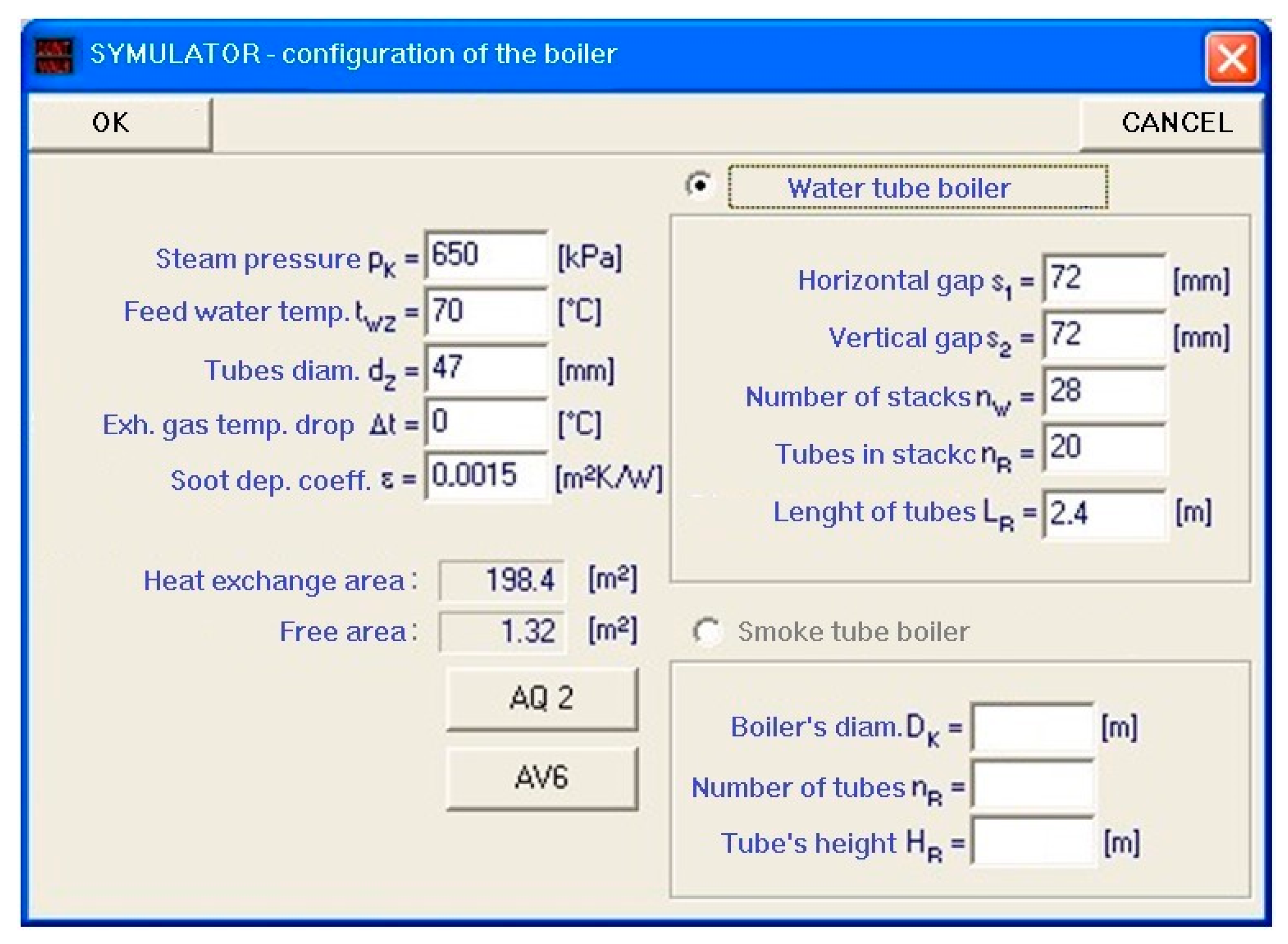
For the above calculation algorithm, a software named SYMULATOR has been developed. It enables to enter previously described data characterizing the EGB. A data entry window is presented in
Figure 5.
3. Results
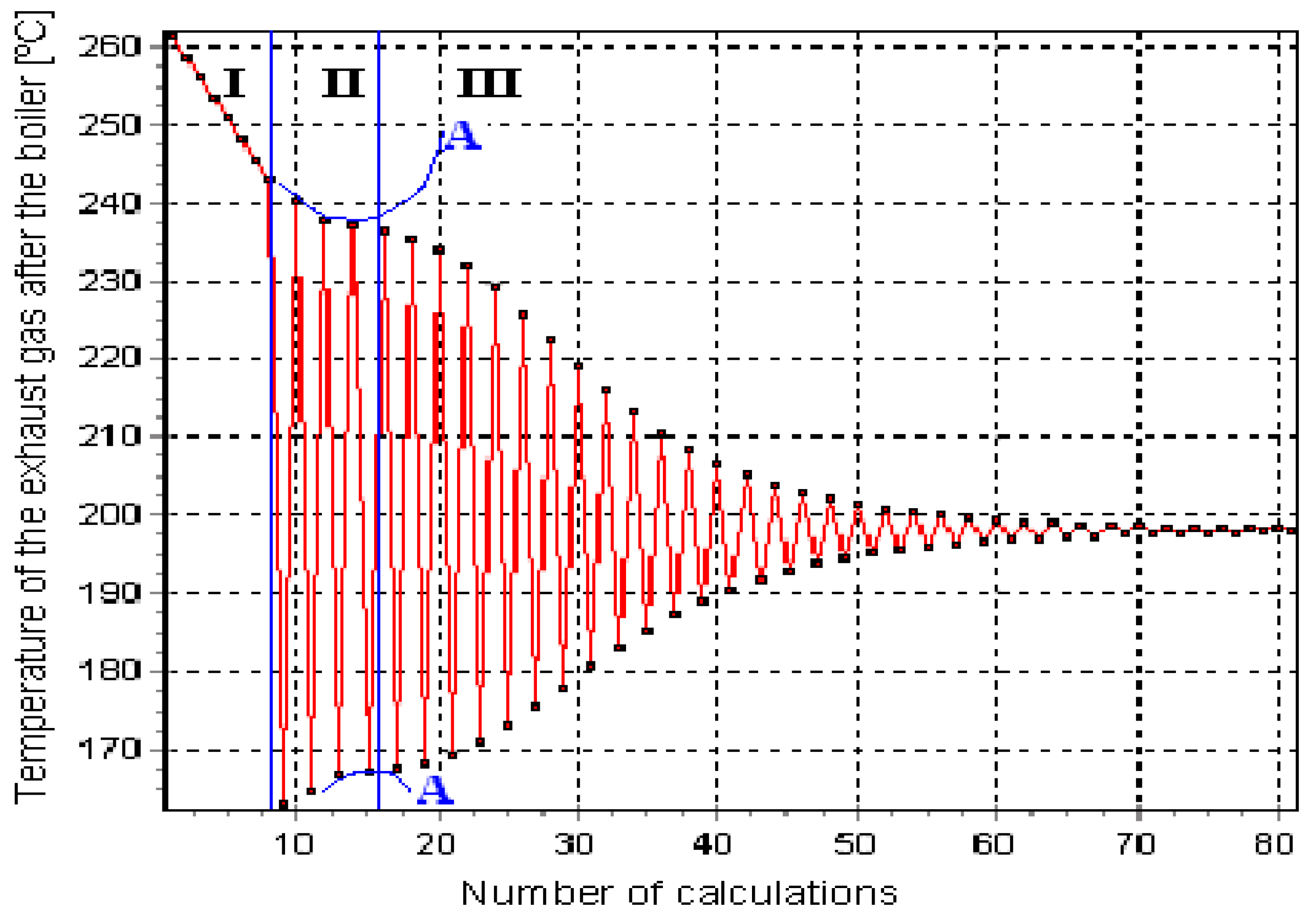
The calculations made by means of the algorithm based on the least squares method lead to results affected by major errors. Such a situation may occur when the calculations are carried out for EGBs fed with exhaust gas at a temperature above 350 °C. The implementation of the limits (boundaries) in the algorithm in terms of the saturation temperature of the produced steam (to 200 °C) and the temperature of the exhaust gas before the EGB (to 350 °C), caused the above error to be removed. For the EGBs with large heat exchange surfaces, the above amendments triggered the obtained results to “disperse” upon achieving initial stabilization. This led to obtaining false values for the amount of steam produced in the exhaust boiler or to the formation of continuous calculation loops during the calculation process. The introduction of an additional filter rejecting control results that do not fall within the limits of the error determined on a current basis, eliminated error and allowed to specify precisely the temperature of the exhaust gas after the boiler, and the amount of recovered heat and produced steam. A sample histogram showing the process of determining the temperature of the exhaust gas after the EGB is presented in
Figure 6 (a printout of the SYMULATOR software). Three stages of calculation process are listed and described:
Stage I—stop activated for “unfinished” loops. The lack of that limit would cause the calculations to be continued for the temperatures that are not in the range determined by the temperature of the boiler feed water and the temperature of the exhaust gas after the EGB. They would be stopped by the software only when the error of exceeding the range of the declared value specifying the calculated result occurs.
Stage II—activated filter rejecting partial results based on the changes of the course of calculation error function. The lack of the said filter would result in carrying out the calculations according to the bottom and upper line ‘A’, vitiated by an increasing error.
Stage III—asymptotic investigation to the sought temperature of the exhaust gas after the EGB.
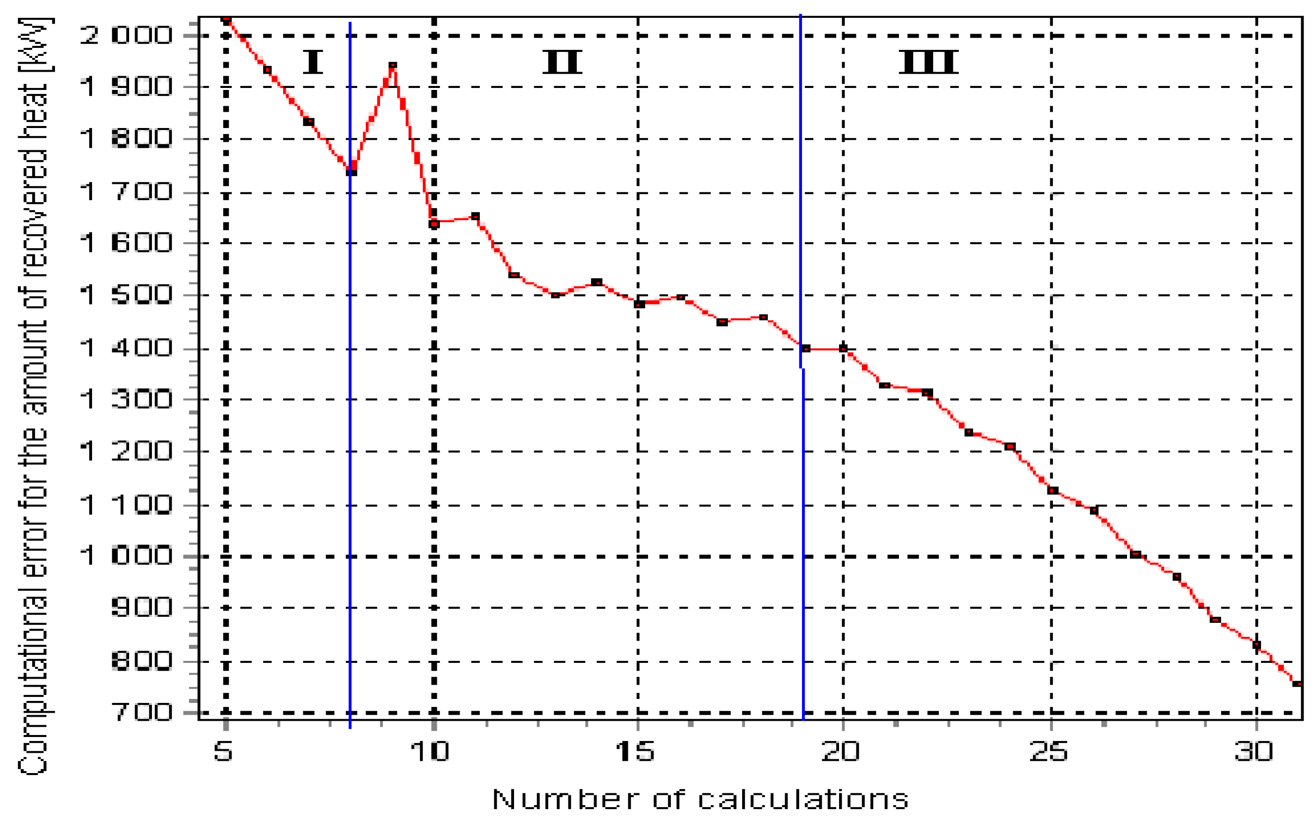
Figure 7 presents a histogram showing the area of the highest filter activity which limited the errors that might occur when the amount of energy recovered in the EGB is determined (a printout of the SYMULATOR software).
In
Figure 7 one may notice a sudden increase of the error value for the value related to the heat recovered in the EGB (the beginning of Stage II) and its even stabilization until achieving a clear downward trend (the end of Stage II).
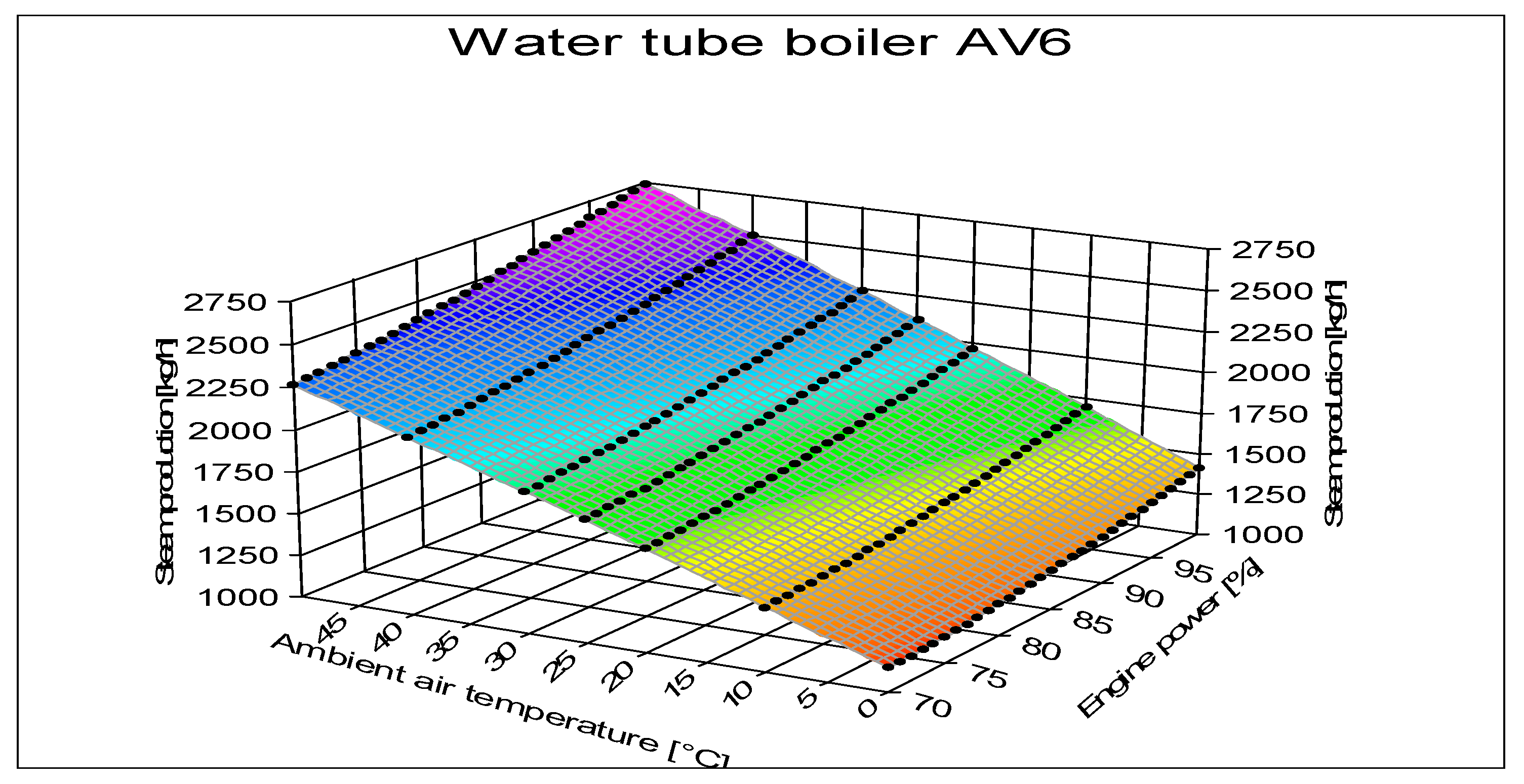
Moreover, the software enables making an assumption on the ambient air temperature which significantly affects the temperature of the exhaust gas feeding the EGB. The results of exemplary simulations of the steam efficiency of a selected boiler (AV6) in relation to the variations in terms of main engine load and the ambient air temperature are presented in
Figure 8.
The accuracy of calculation algorithm results presented in
Figure 4 has been verified by means of the results of the measurements documented during the tests at sea for newly built ships [
16,
17,
18,
19,
20]. The measurement of the steam efficiency of the EGB has been carried out in accordance with the applicable norms and standards and marine classification societies [
25]. Sample, measured values, and computational errors are presented in
Table 2.
The errors’ values, presented in
Table 2, showing the variations between the measured and calculated values have been determined using Equations (18) and (19):
where
DKU is the measured value and
DKUobl is the calculated value:
where
tKU is the measured value and
tKUobl is the calculated value.
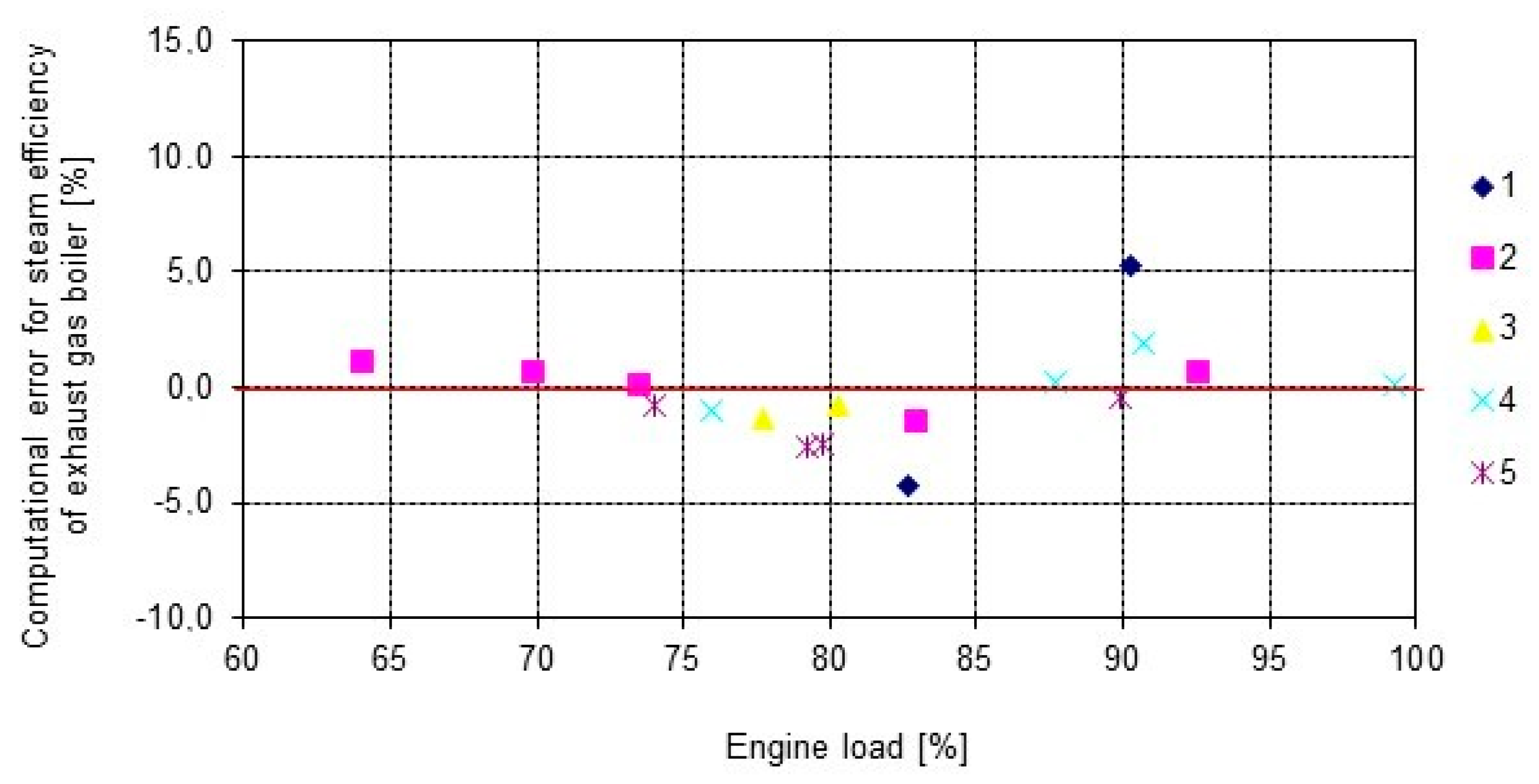
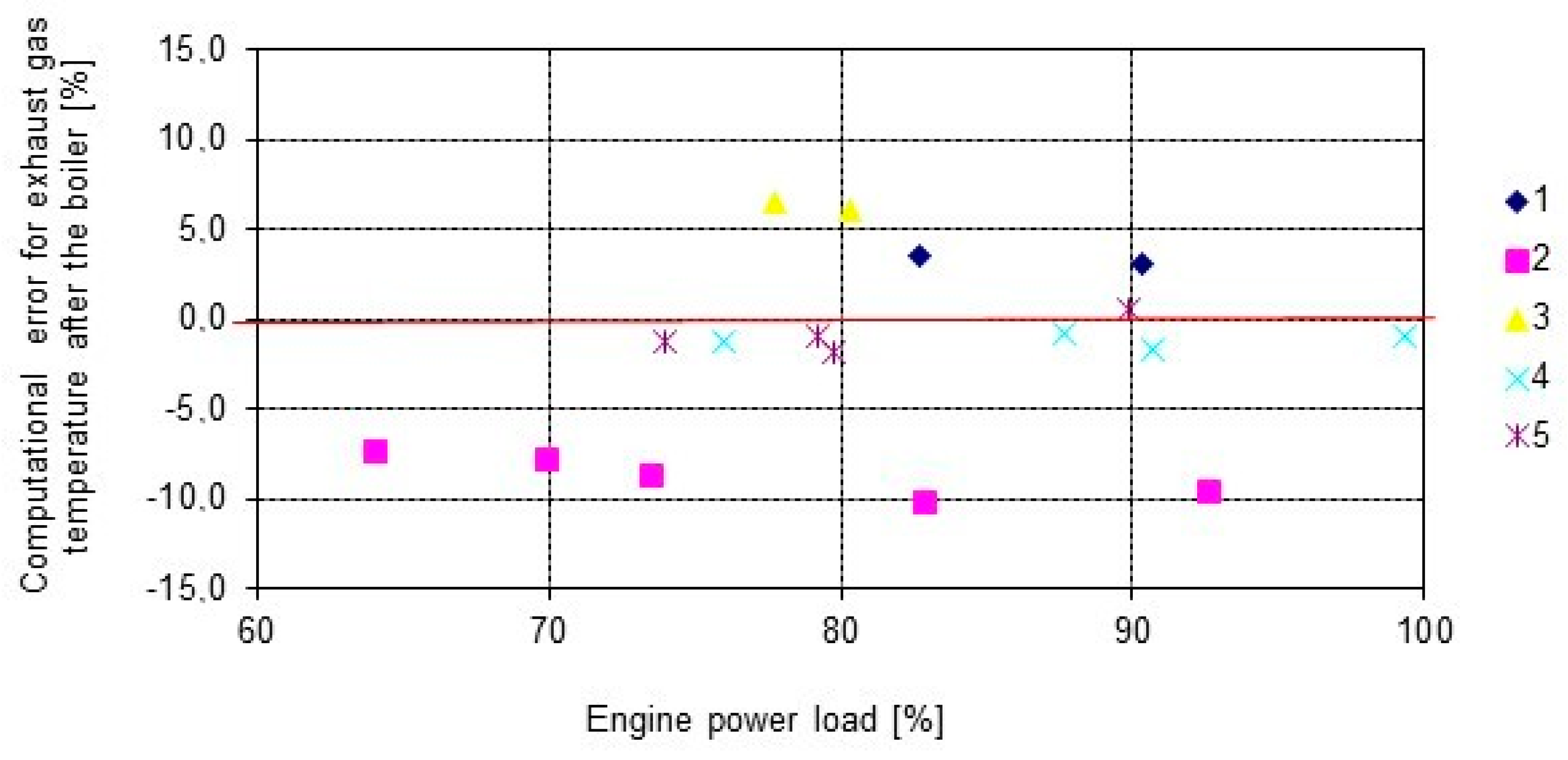
The computational errors’ values for the steam produced in the analyzed EGB, when compared with the measured values, are presented in the form of a chart in
Figure 9. The computational errors values for the exhaust gas temperature at the outlet from the EGB are presented in
Figure 10. In these figures, the following measurement numbers correspond to the numbers of the ships (
Table 2) on which the research was conducted.
The results of the calculations performed in terms of the amount of steam produced by EGB showed that within the engine load above 60% of the nominal load, the maximum computational errors have not exceeded 5%. A significant number of the results fall within the error limit of 3%.
The simulation results for the exhaust gas temperature showed (
Figure 10) that the maximum computational errors have not exceeded 6%, wherein almost all obtained results fall within the error limit not exceeding 4%. In one of the vessels subject to research (
Figure 10, ship 2), one has registered the results characterizing with higher error values than the remaining ones and they fall within the range from 7 to 10%. The reason for such significant differences happened to be a contaminated boiler with soot, which was proven due to the boiler inspection [
1].


