Article

Hierarchical Fault-Tolerant Control using Model Predictive Control for Wind Turbine Pitch Actuator Faults

1
Department of Robot Engineering, Kyungil University, Gyeongsan 38428, Korea
2
School of Electronics Engineering, Kyungpook National University, Daegu 41566, Korea
*
Author to whom correspondence should be addressed.
Energies 2019, 12(16), 3097; https://doi.org/10.3390/en12163097
Submission received: 11 June 2019 / Revised: 2 August 2019 / Accepted: 7 August 2019 / Published: 12 August 2019
(This article belongs to the Special Issue Maintenance Management of Wind Turbines)

Abstract

:
Wind energy is one of the fastest growing energy sources in the world. It is expected that by the end of 2022 the installed capacity will exceed 250 GW thanks to the supply of large scale wind turbines in Europe. However, there are still challenging problems with wind turbines. In particular, off-shore and large-scale wind turbines are required to tackle the issue of maintainability and availability because they are installed in harsh off-shore environments, which may also prevent engineers from accessing the site for immediate repair works. Fault-tolerant control techniques have been widely exploited to overcome this issue. This paper proposes a novel fault-tolerant control strategy for wind turbines. The proposed strategy has a hierarchical structure, consisting of a pitch controller and a wind turbine controller, with parameter estimations using the adaptive fading Kalman filter technique. The pitch controller compensates any fault with a pitching actuator, while the wind turbine controller computes the optimal reference command for pitching behavior so that the effect of the fault with a pitch actuator can be minimized. The performance of the proposed approach is demonstrated through a set of simulations with a wind turbine benchmark model.

1. Introduction

The demand for sustainable and economical renewable energy has been increasing. Wind energy is considered as one of most important renewable energy sources thanks to the fact that wind is an infinite and free source of energy without harmful waste. According to the WindEurope report [1], 11.7 GW of wind power was newly installed in 2018 and there is a total 189 GW of installed wind energy capacity in Europe. This will exceed 250 GW by the end of 2022.
Today, wind turbines are responsible for a large part of the energy production. The high reliability of wind turbines is critical to reduce the cost of operation and maintenance [2,3]. However, wind turbines operate in harsh environments, which causes failure of subsystems, including actuators and sensors. Failure of subsystems or components may result in a change of the overall system structure and performance, either slowly or significantly. Therefore, an appropriate compensation of failure following an early diagnosis has significant impacts on the whole structural safety and the stable energy generation.
The pitch control system plays an important role for the operation of wind turbines. The main purposes of the pitch control include limiting the wind power capture in cases of high wind speed conditions, mitigating the operational load, stalling, and braking in control region 3 with effective wind speeds of 12.5–25 m/s, and stopping the wind energy generation in cases of low wind speed conditions in control region 2 with effective wind speeds of 3–12.5 m/s [4]. Therefore, any fault with the pitch control system may cause serious problems, such as asymmetric loads for blades, fluctuations in the speed of generator and power generation, and degradation of the stability of the wind turbine [5,6].
Recently, researchers have paid attention to fault tolerance control techniques for wind turbines. Fault-tolerant control can be used to improve the reliability of a wind turbine system in harsh operating environments and to guarantee the graceful degradation of performance, even in the event of faults with system components. Some important works include linear parameter variable control [7], adaptive gain sliding mode control [8], fuzzy-based adaptive control [9,10], and nonlinear geometric approach [11]. In previous work [7], the linear matrix inequality is used for active fault-tolerant control, while the bilinear matrix inequality is applied to passive fault-tolerant control. In another study [8], a sliding mode fault-tolerant controller based on gain adaptive control was designed along with the robust sliding mode observer for states, unknown outputs, and sensor faults. In previous work [9,10], fuzzy model reference adaptive control for failure of the torque actuator in a wind turbine was proposed. In another study [11], an active fault-tolerant controller using the nonlinear geometric approach was presented.
The model predictive control (MPC) technique systematically handles constraints and optimizes the controller to satisfy the control objectives [12]. Also, MPC has an implicit capability of fault-tolerance in terms of the prediction of models, constraints, and objective functions [13]. Many researchers have published MPC-based fault-tolerant control for wind turbines [14,15]. In a previous study [14], MPC worked as the nominal controller in normal conditions, while it worked as the pre-compensator in the presence of a fault. In another study [15], MPC was used to accommodate faults with a pitch actuator and a generator torque actuator using the Laguerre function for parameterization of control. Most of the existing research used an objective function that involves the effect of a fault. How to properly adjust the objective function of MPC in response to faults is an interesting research topic [16]. However, it is hard to find publications addressing the design of fault-tolerant MPC cooperating with a fault detection and diagnosis (FDD) module that provides the MPC controller with information regarding faults.
This paper presents a novel fault-tolerant control strategy for wind turbines with a hierarchical architecture in which MPC is cooperated with a FDD module using online estimations of fault parameters. Since MPC can effectively deal with the variation in parameters by using an internal model, the proposed strategy employs MPC as the baseline controller for both the pitch system and the wind turbine. The proposed method comprises two different control modes: (a) fault-tolerant control with the pitch system only; and (b) fault-tolerant control with the pitch system and the wind turbine. The performance of the proposed method is compared with proportional-integral (PI) control and sliding mode control through a set of simulations with a wind turbine benchmark model.

2. Statement of Wind Turbine Problem

In this work, we consider the wind turbine control system benchmark model, which was provided by kk-electronics for the IFAC Fault Detection, Supervision and Safety for Technical Processes (SAFEPROCESS) conference (Figure 1) [17]. The benchmark model represents a horizontal-axis wind turbine with a three-bladed rotor. The model was obtained through a standard approach given in the literature [18]. The wind turbine control system consists of seven subsystems: a wind model, aerodynamics, a drive train, a generator-converter unit, a pitch system, and a tower. In this paper, only necessary parts, including aerodynamics and a pitch system, are presented.

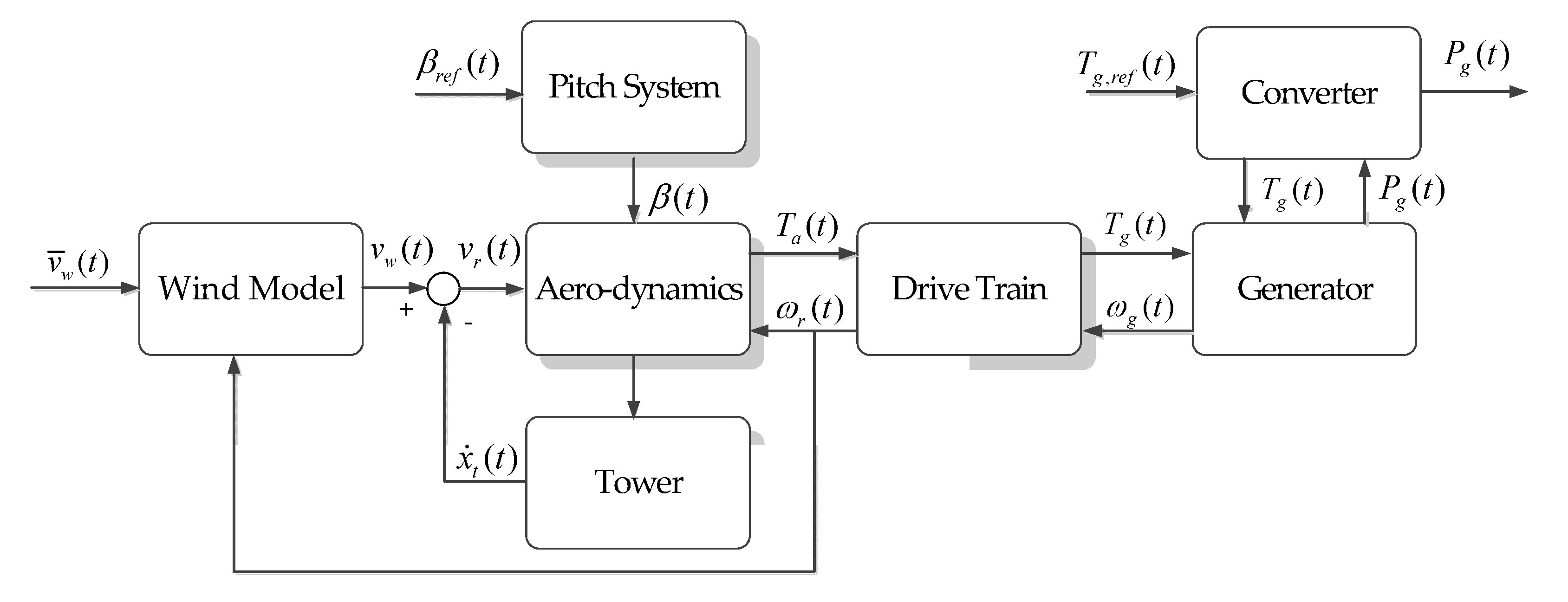
2.1. Description of Wind Turbine Aerodynamics Model

The aerodynamic equations of wind turbines are given in previous work [4,19]. The power available from the wind passing through the entire swept rotor can be expressed as
P w   =   1 2 m ˙ v r 2   =   1 2 ρ π R 2 v r 3
where Pw is the power available from the wind (W), m ˙ is the mass flow rate of the wind, vr is rotor effective wind speed (m/s), ρ is air density (kg/m3), and R is the radius of rotor disc (m). Only a portion of power available Pw is converted to the rotor power, which is represented by the power coefficient, Cp, depending on the tip-speed ratio (λ) and the blade pitch angle (β). The power extracted from the available power Pw is given by.
P a ( t )   =   P w ( t ) C p ( λ ( t ) , β ( t ) )
The tip-speed ratio is defined as the ratio between the tip speed of blades and the rotor effective wind speed
λ   =   ω r ( t ) R v r ( t )
where wr(t) is rotor speed (rad/s). The power coefficient Cp has a theoretical upper limit of 16/27 ≈ 0.593, known as the Betz theory. The aerodynamic torque (Ta) acting on the rotor is defined as
T a ( t )   =   P a ( t ) ω r ( t )   =   1 2 ω r ( t ) ρ π R 2 v r 3 C p ( λ ( t ) , β ( t ) )
In the benchmark model, the blade pitch actuation system has three identical hydraulic actuators. Each hydraulic pitch system is modeled by a second-order system
β ( s ) β r e f ( s )   =   ω n 2 s 2   +   2 ζ ω n s   +   ω n 2
where βref, ωn, and ζ are the reference pitch angle, the natural frequency, and the damping factor of the pitch actuator, respectively.
The pitch control system plays an important role in generating the reference pitch angle to manage the power generation from the wind. At wind speeds below the rate value (<12.5 m/s), the reference pitch angle is set to zero. When wind speeds are above the rate value (>12.5 m/s), the pitch control system aims to keep the generated power around the rated value by adjusting the reference pitch angle. Therefore, this work focuses on the design of fault-tolerant control that can compensate for the effect of the fault with the pitch system.

2.2. Model of Pitch Actuator System Fault

In the benchmark model for a 4.8-MW wind turbine [17], each of the pitch systems is actuated with an identical pitch actuator and assumed to have the same dynamic behavior as described in Equation (5). To facilitate the subsequent controller design, the state space model of the pitch system is rewritten as follows:
[ β ˙ β ¨ ] = [ 0 1 ω n 2 2 ς ω n ] [ β β ˙ ]   +   [ β β ˙ ] β r e f y   =   [ 1 0 ] [ β β ˙ ]
Each actuator has the physical constraints, the min/max magnitudes, and the rates, given as (−2 deg, 90 deg) and (−8 deg/s, +8 deg/s). Each pitch system may have faults due to hydraulic leakage, which will result in the change in dynamics; that is, the variations of ωn and ζ. This kind of fault is modeled as a convex combination of values at the nominal condition and the low-pressure fault, as follows [8]:
ω n 2   =   ω n 0 2   +   ( ω n f 2 ω n 0 2 ) f ς ω n   =   ς 0 ω n 0   +   ( ς f ω n f ς 0 ω n 0 ) f
where ζ0 and ωn0 are the nominal values of ζ and ωn, and ζf and ωnf are their values at a low pressure fault; f represents the fault indicator. That is, f = 0 denotes the normal pressure ζ0 = 0.6 rad/s and ωn0 = 11.11 rad/s, and f = 1 denotes the low-pressure fault with ζf = 0.9 rad/s and ωnf = 3.42 rad/s [17].

3. Design of Hierarchical Fault-Tolerant Model Predictive Control

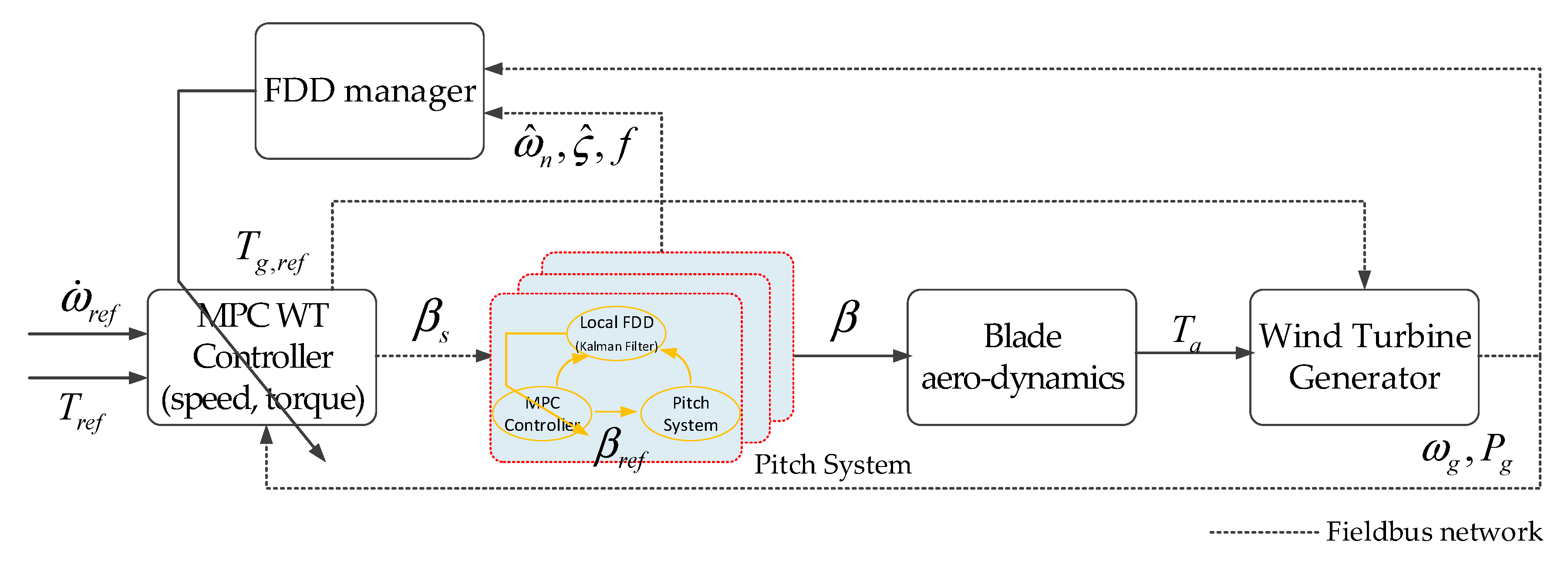
3.1. Control Principle for Wind Turbines

The goals of control for wind turbines are classified into two groups according to the wind speed rate value. For the above wind speed rate value (>12.5 m/s in the benchmark model), the controller aims to regulate the generate power (Pg) around the rated power and also to protect the generator from the limited rotation speed due to the excessive aerodynamic torque. On the contrary, for the below wind speed rate value (<12.5 m/s in the benchmark model), the wind turbine controller aims to drive the turbine rotor speed at the optimal rotating speed by regulating the pitch angle, βr = 0. The regulation of Pg is achieved by regulating Tg (see Equation (4)). Therefore, the control inputs of the wind turbine system are Tg,ref and βref. In this paper, two types of fault-tolerant MPC are designed: one for the generator system (Tg,ref) and another for the pitch system (βref).

3.2. Fault-Tolerant Model Predictive Control for Wind Turbines

The structure of the proposed fault-tolerant control strategy is illustrated in Figure 2. In this strategy, notice that fault accommodation occurs in two places: one is in the pitch system controller (local controller) and the other is in the wind turbine system controller (global controller). For this reason, the proposed method can be seen as “fault-tolerant control with a hierarchical structure”. In practice, the fault-tolerant MPC for the pitch system compensates for the effects of faults in the pitch system as much as possible using online estimations of fault parameters. If the performance degradation persists, then the fault-tolerant MPC for the wind turbine system attempts to meet the overall performance requirements. This judgment is made by the FDD manager based on information of the wind turbine condition, including the fault index, the power generation, the generator speed, etc. The local FDD module provides specific information regarding faults, such as the fault index and estimations of fault parameters using the adaptive fading Kalman filter algorithm [20,21]. Online estimations of fault parameters and the decision regarding the fault-tolerant control form the FDD algorithm, which will be discussed in a separate paper. An extensive survey of FDD can be found in previous work [22].

3.2.1. Design of Fault-Tolerant MPC for the Pitch System

The purpose of the fault-tolerant MPC for the pitch system is to control the pitch system, even if any fault with the pitch actuator occurs, so that the discrepancy between the response of a nominal system and the response of a faulty system can be minimized. The fault-tolerant MPC for the pitch system can be formulated as follows if accurate estimates of the parameter are available:
min Δ β r e f J ( k )   =   i = i N p β ^ ( k   +   i | k ) β s ( k   +   i | k ) Q 2   +   i = i N u Δ β r e f ( k   +   i ) R 2 subject   to :   pitch   system   model   in   Equation   ( 5 ) β min < β r e f < β max Δ β min < Δ β r e f < Δ β max
where β ^ , β s and Δ β r e f denote the estimated pitch angle, the pitch angle set-point given from the wind turbine system controller, and the variation in the pitch angle reference, respectively. Np is the length of the prediction horizon, Nu is the length of the control horizon, and Q and R are weighting matrices. When solving the optimization problem given in Equation (8), all of the system parameters are updated via the adaptive fading Kalman filter algorithm to reflect the effect of the fault with the pitch system at every sampling time.

3.2.2. Design of Fault-Tolerant MPC for the Wind Turbine System

The main purpose of the fault-tolerant MPC for the wind turbine system is to meet the operating requirements of the wind turbine and to generate the maximum electric power available at the current wind speed, which often varies. Furthermore, to achieve the capability of fault tolerance, the wind turbine system controller must be able to compensate for the effect of a fault that cannot be completely compensated by the fault-tolerant MPC for the pitch system. The wind turbine should be maintained at maximum power while not exceeding the safe electrical and mechanical loads. These requirements can be expressed in the optimization problem as follows:
min Δ β s J ( k )   =   i = i N p y ( k   +   i | k ) r ( k   +   i | k ) Q 2   +   i = i N u Δ β s ( k + i ) R 2 subject   to :   wind   turbine   model   in   Section   2 β min < β s < β max
where Np and Nu are the lengths of the prediction horizon and the control horizon, respectively. Here, y is the output vector of the wind turbine system, r is the reference vector, which may change according to the wind speed; Δ β s is the variation of the pitch angle set-point, and Q and R are weighting matrices. The output vector y and the reference vector r are defined as
y   =   [ ω ˙ g T g ] ,   r   =   [ 0 P r e f η g ω r e f ]
where ω ˙ g is time rate of the change of the generator angular speed, Tg is the current generator torque, Pref is the power generation reference (it is a constant value, which is 4.8 MW in this paper), ηg is a coefficient, and ωg is the current generator angular speed at the given sampling time. Table 1 summarizes the control parameters for MPC.

4. Simulation Results

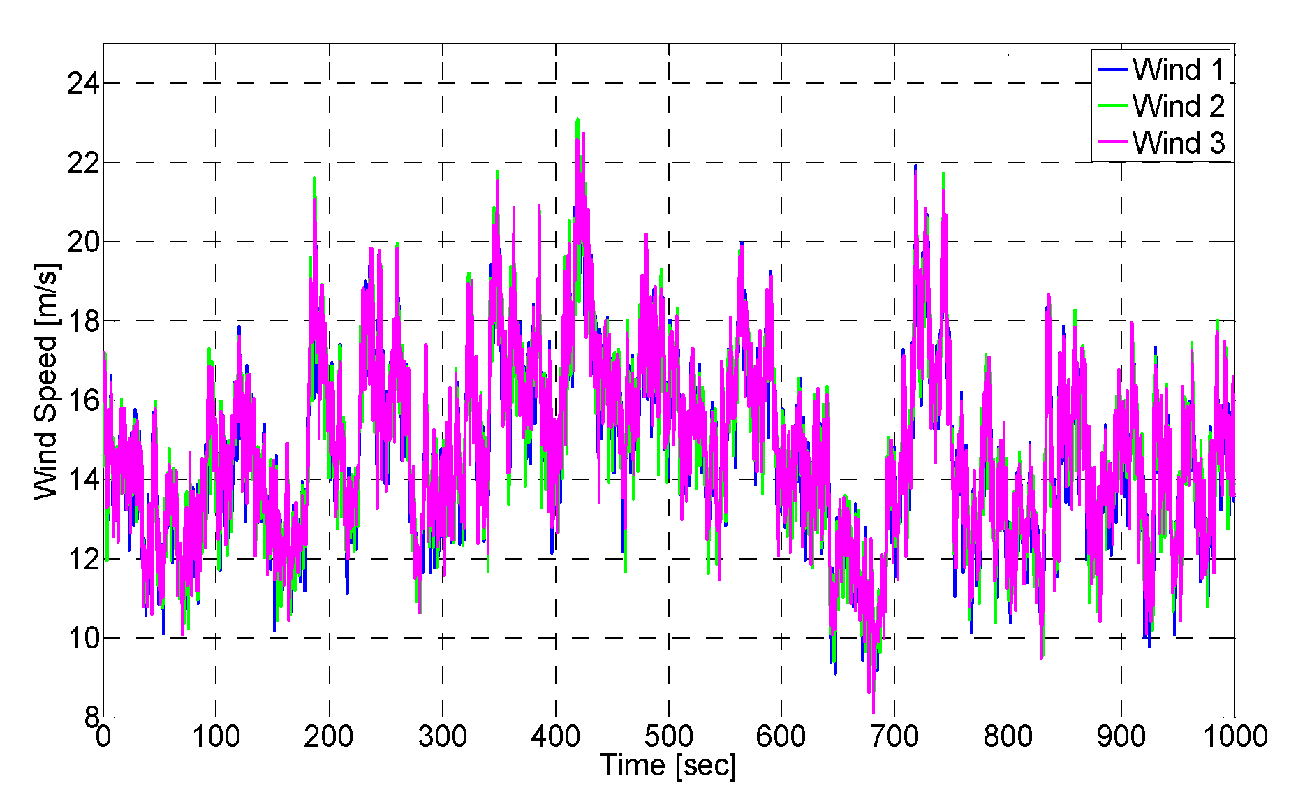
4.1. Wind Turbine Benchmark Model

The effectiveness of the proposed method is verified through simulations with the wind turbine benchmark model in both the nominal case and the fault case with a pitch fault. The wind turbine benchmark model, which is developed in the MATLAB/Simulink® (R2014A, MathWorks, Natick, MA, USA) programming environment, was introduced in the design competition by IFAC SAFEPROCESS [17]. In the benchmark model, a basic PI controller for pitch control is implemented with proportional gain of 4 and integrator gain of 1 [6]. To evaluate the performance of the proposed approach, sliding mode control (SMC) for a wind turbine is also implemented [23]. Simulations were performed for three cases, which are: (a) no FTC for the wind turbine system, FTC for the pitch system; and (b) FTC for both the pitch and the wind turbine system. The parameters and variables used in the wind turbine benchmark model and fault-tolerant MPC are summarized as follows:
SymbolDescription
β blade pitch angle for [°]
β ˙ change of pitch angle [°/s]
β s set-point of pitch angle for pitch controller [°]
β r e f reference of pitch angle for pitch system [°]
β ^ estimation of pitch angle [°]
ω ^ n estimation of natural frequency pitch system [rad/s]
ς ^ estimation of damping factor pitch system [rad/s]
f estimation of fault index for pitch system [rad/s]
P r e f rated power generation (4.8 × 10⁶) [W]
T r e f rated generator torque [Nm]
ω r e f rated generator angular speed (162) [rad/s]
P g current generated power [W]
P g , e error of generated power ( P r e f P g ) [w]
ω g current generator angular speed [rad/s]
ω g , e error of generator angular speed ( ω r e f ω g ) [rad/s]

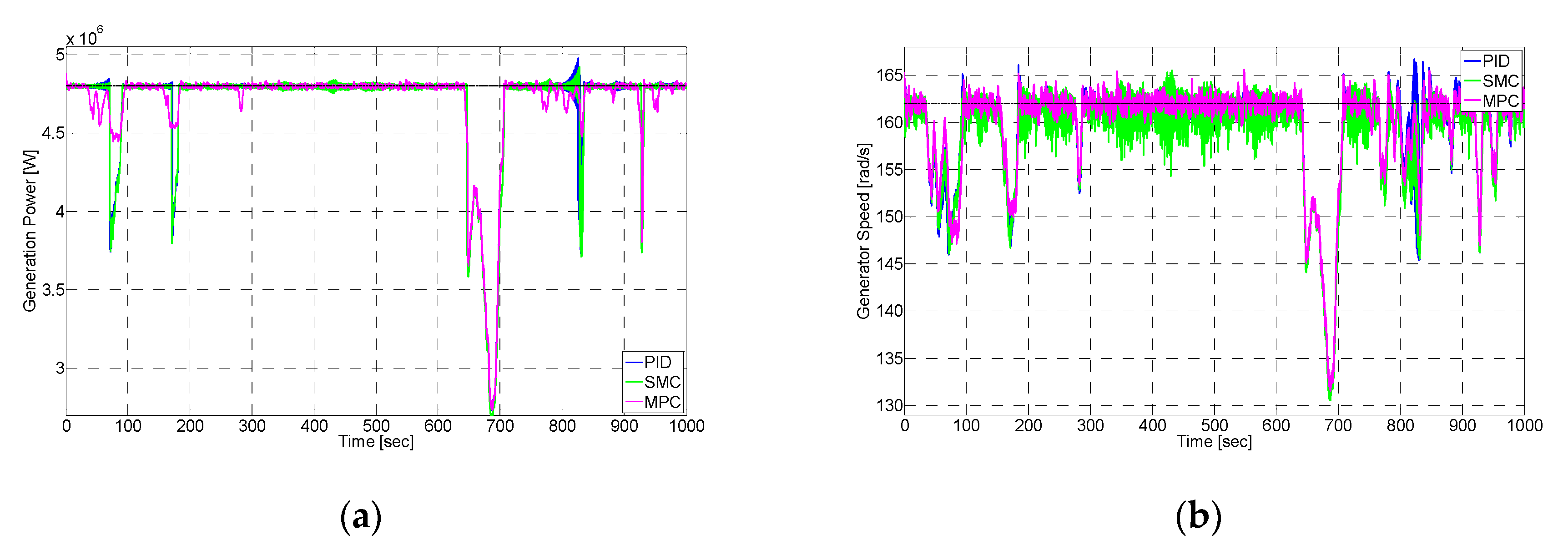
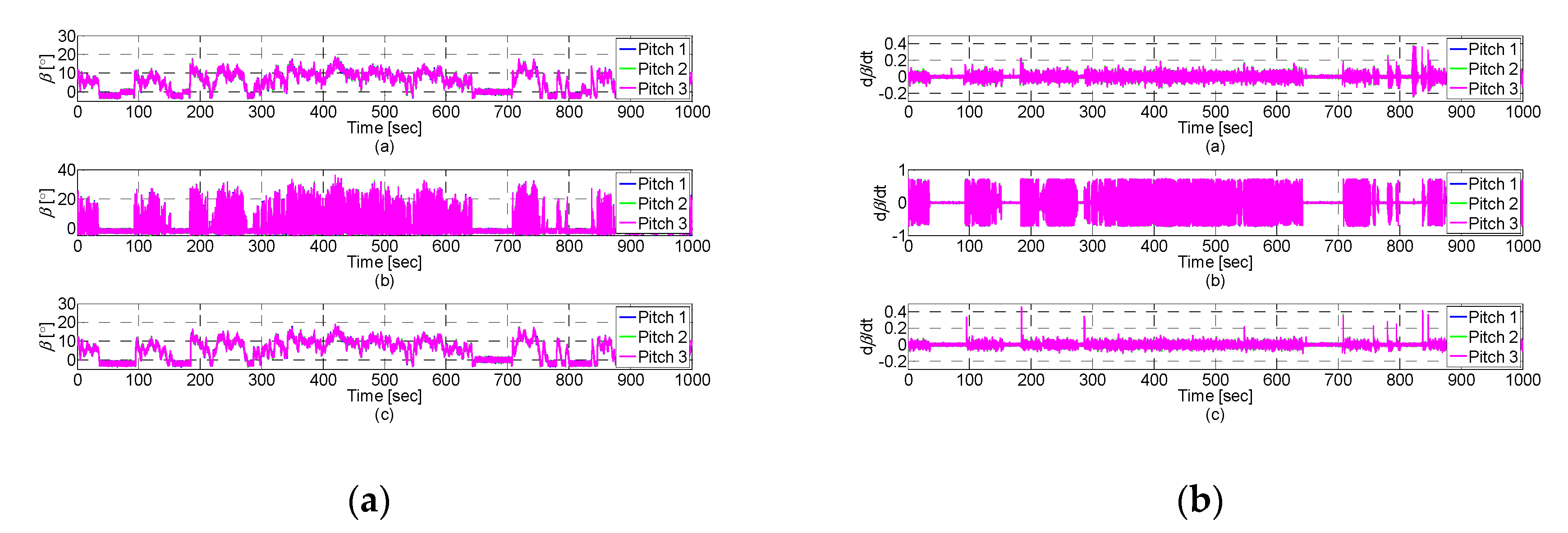
4.2. Simulations for Healthy/Fault-Free Condtion

Simulations are carried out to compare the performance of the reference PI controller and the proposed MPC for the healthy condition. The simulation is executed using the actual wind data that are provided with the benchmark model. Figure 3 is the actual wind profile of each blade (blade 1, blade 2, and blade 3) used throughout the simulations. For a more realistic model of aerodynamics, the wind profile includes the effects of tower shadow and wind shear. The simulation results are given in Figure 4 and Figure 5.
The responses with both controllers look similar. The power generation is well controlled near the rated power limit, which can be observed in Figure 4a. Table 2 summaries the simulation results. Three metrics are employed to compare the performance of the different control methods: (1) the sum of squared power generation error (Pg,e) = Pg,e Pg,e; (2) the sum of squared generator speed error (ωg,e); and (3) the sum of squared second blade pitch rate ( β ˙ 2 ) to measure the energy consumption by actuators. As shown in Table 2, the MPC shows a better performance than PI and SMC. The MPC is superior to PI in all performance indices, the power generation, and the energy consumption. In particular, the level of energy consumption with MPC shows an outstanding result.

4.3. Simulations for Faulty Condtion

The simulation results with faults of the pitch system are presented in Figure 6 and Figure 7. The fault occurs in the hydraulic pumps driving the pitch actuators for blades 2 and 3, and they occur abruptly at approximately t = 200 seconds. The same wind profile shown in Figure 3 is used. Note that PI and SMC controllers present the instability at t = 300 and 650 s, respectively. This behavior may be related to the relatively low wind speed at t = 300 s and the pitch actuation fault. Figure 6a shows the power generation curve. It can be observed that the power output with PI or SMC and MPC are quite different under the pitch actuation fault. In the results with SMC, it is obvious that the model uncertainties due to the pitch system fault are larger than the robust region of SMC. The power output with MPC tracks the rated value well, but there is a large variation in the power output curve for the PI and SMC controllers. These results are reflected in the generator speed curve, shown in Figure 6b. This is related to the sluggish response of the pitch system because of the fault and the decrease of the wind speed around t = 300 s. Finally, the proposed MPC outperforms the PI and SMC controllers with respect to the input actuation cost, as shown in Figure 7b. Although there is considerable activity in the pitch system in response to the fault, the PI and SMC controller do not work properly. Table 3 summarizes the performance metrics. As mentioned, PI and SMC show poor control performance. On the other hand, MPC shows a better performance than PI or SMC due to its intrinsic robustness.

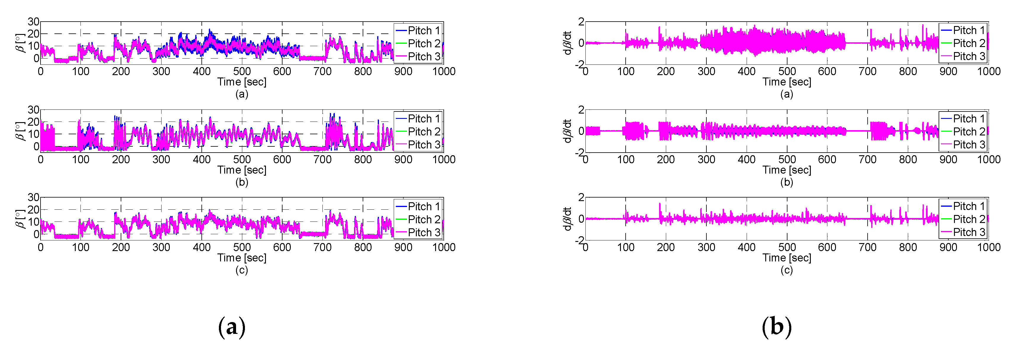
4.4. Simulations with Fault-Tolerant Control in Faulty Condtions

In this section, simulation results for fault-tolerant control in the pitch system fault are presented. The same fault scenario as described in the previous section is used to verify the effectiveness of the proposed fault-tolerant control strategy. In this section, two fault-tolerant strategies are evaluated, which are divided into FTC with the pitch system only and FTC with both the pitch system and the wind turbine system.

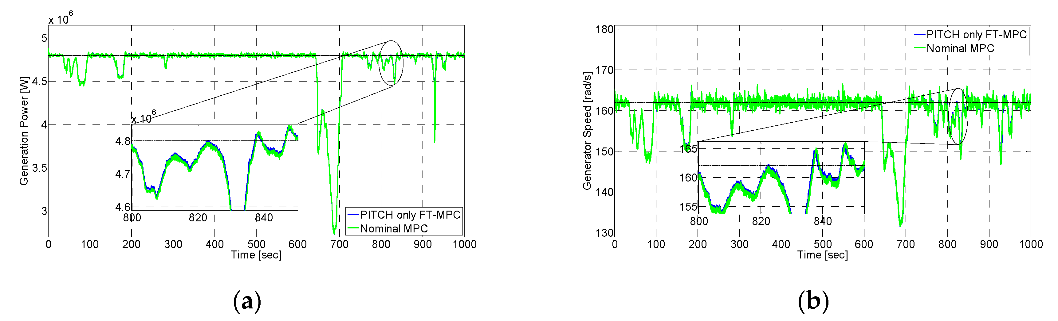
4.4.1. Fault-Tolerant Control with Pitch System Only

First, fault-tolerant control of the pitch system is considered. When the fault occurs, the change of parameter values due to the pitch system fault is estimated by using the adaptive fading Kalman filter. Then, MPC is re-synthesized based on the new set of pitch system parameters. The simulation results are given in Figure 8 and Figure 9. To highlight the effectiveness, the simulation results with and without FTC are compared. Unfortunately, fault-tolerant control with the pitch system only does not work effectively. As shown in Figure 8, the power generation curves and the generator speed curves for the two controllers are similar. There is only slight improvements when FTC is applied. Moreover, Table 4 shows that the improvements are achieved at the expense of pitch actuation energy. The overuse of the faulty pitch system may cause other problems, such as the reduction in remaining useful lifetime (RUL). Therefore, it is concluded that fault-tolerant control with the pitch system only is not reasonable.

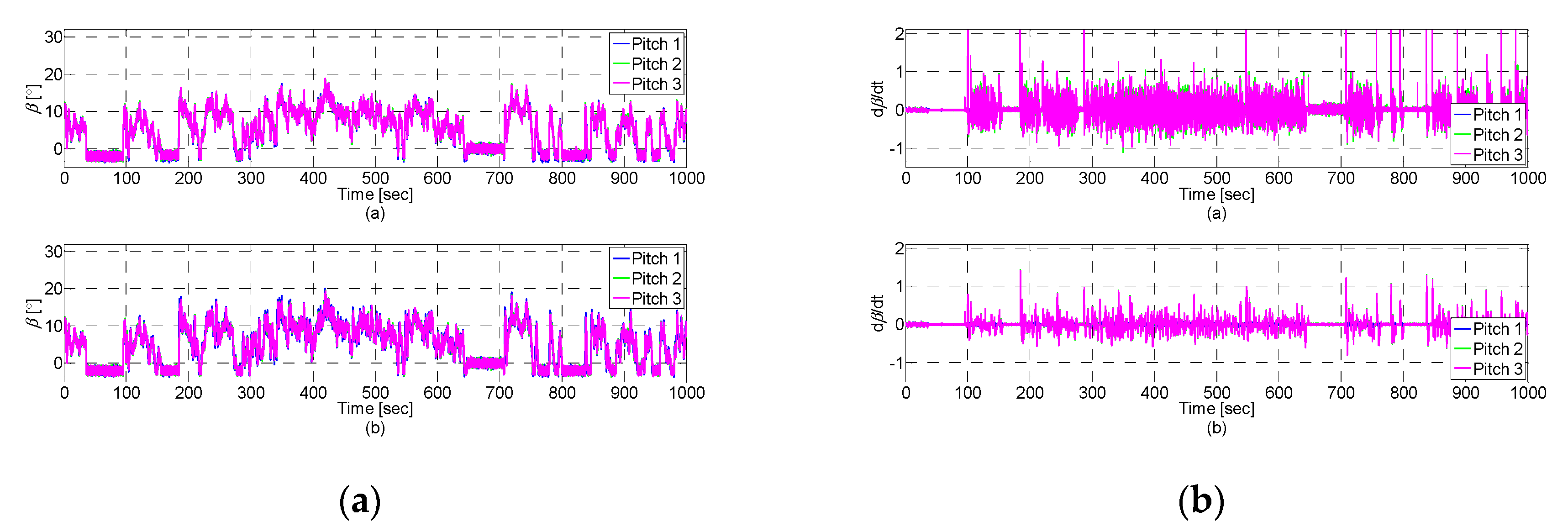
4.4.2. Fault-Tolerant Control with Pitch and Wind Turbine System

This section presents the simulation results of the proposed MPC with both the pitch system and the wind turbine system. The results are compared with and without reconfiguration. In Figure 10 and Figure 11, the power generation curves and the generator speed curves for the two controllers are similar. However, notice the important difference in Figure 11. Figure 11a shows the individual blade pitch angle without and with fault-tolerant control, respectively. A significant difference between the two control methods is evident. In the nominal MPC method, the three pitch actuators are used equally to control the aerodynamic force, even though blades 2 and 3 have faults. This difference occurs because the nominal MPC controller does not have any information about the pitch system condition.
In contrast, FTC with both the pitch system and the wind turbine system increases the movement of healthy blade 1 to regulate the power generation, instead of blades 2 and 3, which are faulty. Therefore, this approach is more reasonable than FTC with the pitch system only. The results are summarized in Table 4. All performance indices show the benefit of FTC with the pitch system and the wind turbine system. The power generation and the generator speed regulation are slightly better than FTC with the pitch system only. Notably, the pitch actuation energy cost of blade 2 is reduced by more than 50% compared with the nominal MPC method. It is expected that saving the pitch actuation energy cost of the faulty pitch system will extend its RUL, which will lead to the lower maintenance costs.

4.5. Discussion

As shown in Table 3 and Table 4, the proposed MPC shows better performance than existing methods in the case of a pitch system fault. Especially, the hierarchical (or two-stage) fault tolerant control strategy reduces the pitch actuation energy cost more than 50%. This will extend the remaining useful lifetime (RUL) of the pitch system, and thus reduce the maintenance costs. However, the large difference in pitch angles between the blades may cause a problem with asymmetric loads and fatigue. To tackle this problem, it is required to design a MPC optimization cost function covering the unbalanced load mitigation problem [24].

5. Conclusions

Wind turbines must satisfy a high degree of reliability to guarantee unrelenting power generation, while reducing the operational and maintenance costs. However, the harsh operating environments of wind turbines can cause failure of subsystems, including actuators and sensors. In this paper, a novel fault-tolerant control strategy for wind turbines has been proposed. The proposed strategy has a hierarchical structure, which consists of two fault tolerant controllers: one for the pitch system at the lower level, and another for the wind turbine system at the higher level. The proposed control strategy is based on the model predictive control (MPC) technique, thanks to its advantage in dealing with the model variations and the uncertainty caused by faults. A set of simulation results with a benchmark model demonstrated the performance of the proposed method in comparison with the existing PI and SMC controllers.

Author Contributions

Conceptualization, D.K.; methodology, D.K.; software, D.K.; writing—original draft preparation, D.K.; writing—review and editing, D.L.; supervision, D.L.; project administration, D.L.; funding acquisition, D.L.

Funding

This work was supported by the National Research Foundation of Korea (NRF) grant funded by the Korea government (MSIT) (No. NRF-2017R1C1B5076020 and NRF-2017R1A2B4003008).

Conflicts of Interest

The authors declare no conflict of interest.

References

  1. WindEuripe. Available online: https://windeurope.org/ (accessed on 10 June 2019).
  2. Kaldellis, J.K.; Zafirakis, D. The wind energy (r) evolution: A short review of a long history. Renew. Energy 2011, 36, 1887–1901. [Google Scholar] [CrossRef]
  3. Njiri, J.G.; Söffker, D. State-of-the-art in wind turbine control: Trends and challenges. Renew. Sustain. Energy Rev. 2016, 60, 377–393. [Google Scholar] [CrossRef]
  4. Burton, T.; Jenkins, N.; Sharpe, D.; Bossanyi, E. Wind Energy Handbook; John Wiley & Sons: Hoboken, NJ, USA, 2011. [Google Scholar]
  5. Ribrant, J.; Bertling, L. Survey of failures in wind power systems with focus on Swedish wind power plants during 1997–2005. IEEE Trans. Energy Convers. 2007, 22, 1–8. [Google Scholar] [CrossRef]
  6. Odgaard, P.F.; Stoustrup, J.; Kinnaert, M. Fault-tolerant control of wind turbines: A benchmark model. IEEE Trans. Control Syst. Technol. 2013, 21, 1168–1182. [Google Scholar] [CrossRef]
  7. Sloth, C.; Esbensen, T.; Stoustrup, J. Robust and fault-tolerant linear parameter varying control of wind turbines. Mechatronics 2011, 21, 645–659. [Google Scholar] [CrossRef]
  8. Lan, J.; Patton, R.; Zhu, X. Fault-tolerant wind turbine pitch control using adaptive sliding mode estimation. Renew. Energy 2018, 116, 219–231. [Google Scholar] [CrossRef]
  9. Badihi, H.; Zhang, Y.; Hong, H. Wind turbine fault diagnosis and fault-tolerant torque load control against actuator faults. IEEE Trans. Control Syst. Technol. 2015, 23, 1351–1372. [Google Scholar] [CrossRef]
  10. Badihi, H.; Zhang, Y.; Hong, H. Fuzzy Gain-Scheduled Active Fault-Tolerant Control of a Wind Turbine. J. Frankl. Inst. 2014, 351, 3677–3706. [Google Scholar] [CrossRef]
  11. Simani, S.; Castaldi, P. Active Actuator Fault-Tolerant Control of a Wind Turbine Benchmark Model. Int. J. Robust Nonlinear Control 2014, 24, 1283–1303. [Google Scholar] [CrossRef]
  12. Maciejowski, J. Predictive Control with Constraints; Prentice Hall: Upper Saddle River, NJ, USA, 2000. [Google Scholar]
  13. Maciejowski, J. The Implicit Daisy-Chaining Property of Constrained Predictive Control. Appl. Math. Comput. Sci. 1998, 8, 101–117. [Google Scholar]
  14. Yang, X.; Maciejowski, J. Fault-tolerant model predictive control of a wind turbine benchmark. In Proceedings of the 8th IFAC Symposium on Fault Detection, Supervision and Safety of Technical Processes (SAFEPROCESS), Mexico City, Mexico, 29–31 August 2012; pp. 337–342. [Google Scholar]
  15. Benlahrache, M.A.; Othman, S.; Sheibat-Othman, N. Faults Tolerant Control of Wind Turbine Based On Laguerre Model Predictive Compensator. In Proceedings of the 2015 European Control Conference (ECC), Linz, Austria, 15–17 July 2015; pp. 3653–3658. [Google Scholar]
  16. Shi, T.; Xiang, X.; Wang, L.; Zhang, Y.; Sun, D. Stochastic Model Predictive Fault Tolerant Control Based on Conditional Value at Risk for Wind Energy Conversion System. Energies 2018, 11, 193. [Google Scholar] [Green Version]
  17. Odgaard, P.; Stoustrup, J.; Kinnaert, M. Fault tolerant control of wind turbines—A benchmark model. IFAC Proc. Vol. 2009, 42, 155–160. [Google Scholar] [CrossRef]
  18. Esbensen, T.; Sloth, C. Fault Diagnosis and Fault-tolerant Control of Wind Turbines. Master’s Thesis, Faculty of Engineering, Aalborg University, Aalborg, Danmark, 2009. [Google Scholar]
  19. Bianchi, F.D.; Battista, H.; Mantz, R.J. Wind Turbine Control Systems: Principles, Modelling and Gain Scheduling Design; Springer: London, UK, 2007. [Google Scholar]
  20. Kim, J.; Kiss, B.; Lee, D. An adaptive unscented Kalman filtering approach using selective scaling. In Proceedings of the IEEE International Conference on Systems, Man and Cybernetics (SMC), Budapest, Hungary, 9–12 October 2016; pp. 784–789. [Google Scholar]
  21. Kim, K.; Lee, J.; Park, C. Adaptive Two-Stage Extended Kalman Filter for Fault-Tolerant INS-GPS Loosely Coupled System. IEEE Trans. Aerosp. Electron. Syst. 2009, 45, 125–137. [Google Scholar]
  22. Gao, Z.; Cecati, C.; Ding, S. A Survey of Fault Diagnosis and Fault-Tolerant Techniques-Part I: Fault Diagnosis with Model-Based and Signal-Based Approaches. IEEE Trans. Ind. Electron. 2015, 62, 3757–3767. [Google Scholar] [CrossRef]
  23. Lee, S.; Joo, Y.; Back, J.; Seo, J.; Choy, I. Sliding mode controller for torque and pitch control of PMSG wind power systems. J. Power Electron. 2011, 11, 342–349. [Google Scholar] [CrossRef]
  24. Liu, Y.; Patton, R.; Lan, J. Fault-tolerant Individual Pitch Control using Adaptive Sliding Mode Observer. In Proceedings of the 10th IFAC Symposium on Fault Detection, Supervision and Safety of Technical Processes (SAFEPROCESS), Warsaw, Poland, 29–31 August 2018; pp. 1127–1132. [Google Scholar]
Figure 1. Wind turbine control system model [18].
Energies 12 03097 g001
Figure 2. Hierarchical structure of the proposed fault-tolerant control.
Energies 12 03097 g002
Figure 3. Actual wind profile of each blade, including the effects of tower shadow and wind shear.
Energies 12 03097 g003
Figure 4. Simulation results with healthy conditions: (a) power generation; (b) generator speed.
Energies 12 03097 g004
Figure 5. Simulation results with healthy conditions: (a) pitch angle; (b) pitch angular rate (top: PI; mid: SMC; bottom: MPC).
Energies 12 03097 g005
Figure 6. Simulation results with fault conditions: (a) power generation; (b) generator speed.
Energies 12 03097 g006
Figure 7. Simulation results with faulty conditions: (a) pitch angle; (b) pitch angular rate (top: PI; mid: SMC; bottom: MPC).
Energies 12 03097 g007
Figure 8. Simulation results with fault-tolerant control with pitch system only: (a) power generation; (b) generator speed.
Energies 12 03097 g008
Figure 9. Simulation results with fault-tolerant control with pitch system only: (a) pitch angle; (b) pitch angular rate (top: fault-tolerant with MPC (FT-MPC); bottom: nominal MPC).
Energies 12 03097 g009
Figure 10. Simulation results with fault-tolerant control with pitch and wind turbine systems: (a) power generation; (b) generator speed.
Energies 12 03097 g010
Figure 11. Simulation results with fault-tolerant control with pitch and wind turbine systems: (a) pitch angle; (b) pitch angular rate (top: FT-MPC; bottom: nominal MPC).
Energies 12 03097 g011
Table 1. Model predictive control parameters for implementation.
ParametersNotationValue
Sampling Period-0.01
Prediction HorizonNp20
Control HorizonNu2
Output Constraint Min/Max β min / β max −2/90
Output Constraint Rate Up/Down Δ β min / Δ β max 8/−8
Input/Output WeightR/Q0.1/1
Table 2. Controller performance in healthy conditions (the numbers in parentheses denote normalized values with respect to the PI controller).
Controller ( P g , e ( t ) ) 2 d t   [ 10 16 ] ( ω g , e ( t ) ) 2 d t   [ 10 6 ] ( β ˙ 2 ( t ) ) 2 d t   [ 10 2 ]
PI1.0380
(1)
2.6868
(1)
1.2618
(1)
SMC1.1479
(1.11)
3.0746
(1.14)
79.2850
(62.8)
MPC0.97361
(0.938)
2.5886
(0.963)
0.5745
(0.455)
Table 3. Controller performance in faulty conditions (the numbers in parentheses denote normalized values with respect to the PI controller).
Controller ( P g , e ( t ) ) 2 d t   [ 10 16 ] ( ω g , e ( t ) ) 2 d t   [ 10 6 ] ( β ˙ 2 ( t ) ) 2 d t   [ 10 4 ]
PI1.3809
(1)
5.7436
(1)
1.0195
(1)
SMC1.7812
(1.29)
8.4175
(1.47)
0.8687
(0.852)
MPC0.9736
(0.705)
2.6120
(0.455)
0.3444
(0.338)
Table 4. Controller performance with and without fault-tolerant control (the numbers in parentheses denote normalized values with respect to the MPC).
Controller ( P g , e ( t ) ) 2 d t   [ 10 15 ] ( ω g , e ( t ) ) 2 d t   [ 10 6 ] ( β ˙ 2 ( t ) ) 2 d t   [ 10 3 ]
Nominal MPC9.7363
(1)
2.6120
(1)
3.4449
(1)
FTC with pitch system only9.7085
(0.997)
2.5649
(0.982)
6.2457
(1.81)
FTC with pitch and wind turbine systems9.6849
(0.995)
2.5407
(0.973)
1.6201
(0.470)

