Abstract
Biomass, as a renewable and clean energy resource, plays a vital role in energy security and greenhouse gas reduction across the world. This paper reports on our newly established technology: a downdraft fixed-bed biomass gasification system using nut shells (mainly apricot kernel shells) for electricity generation, heating and partially activated carbon production at the same time. Particularly, the key features of the gasification reactor will be presented in detail. In the commercial plant (3 MW scale) located in Hebei province, China, the typical energy conversion from apricot kernel shell gasification is as follows: 47% syngas, 44% char (partially activated carbon), 5% hot water, and 4% energy loss. The main gasification temperature is 600–800 °C, while the activation zone is 850–900 °C. The commercial system has currently been in operation for 4 years. Considering the partially activated carbon as a stable carbon carrier, the whole system features negative CO2 emissions.
1. Introduction
Gasification has been considered as a promising technological process for converting biomass into syngas consisting primarily of H2, CO, CO2, and CH4, which can be flexibly used for electricity generation in gas engines, used as building blocks to synthesize liquid fuels, or used as a hydrogen-rich gas for the refinery industry and fuel cells. Although intensive fundamental [1,2,3] and demonstrative studies [4,5] have been conducted in the past decades both in academic and industrial societies, there are still few reports on economic and reliable biomass gasification technologies at commercial scales. A few key barriers are responsible for the difficulties in developing and commercializing gasification technologies. (1) The preparation of biomass feedstock, including collection, drying, transportation, chipping, and even pelletizing, can be very expensive. Therefore, the cost related to biomass supply must firstly be considered before commencing to establish a biomass gasification plant; (2) The feeder, as the first key unit for the gasification system, has to be well-designed and pre-tested as biomass flowability is very poor, thus easily causing bridging and blocking issues; (3) The poor flowability of biomass inside the gasification reactor could also lead to gas channeling, localized high temperature, slag formation, and so on; (4) The purpose of gasification is to convert the carbonaceous materials into gaseous products as completely as possible. Therefore, the carbon residue should be kept to a minimum amount. The quick and complete carbon conversion could be significantly enhanced by increasing reaction temperature and pressure. The high reaction temperature would, however, more or less bring slagging issues; (5) The gas products at the exit of the gasifier normally contain significant amounts of dust (fly ash and char fines) and tarry materials, which have to be cleaned before the gas could be used as an end product.
Barriers 2 and 3 should be tackled by mechanical approaches, while barrier 4 can be coped with an appropriate gasifier design and optimal reaction conditions. Alternatively, the change in gasification concept may help to overcome the technological barrier. For example, the acceptance of carbon (char) production could not only ease the experimental condition and operation, but also have char as valuable products. Barrier 5 is probably the issue causing the most fouling which has been widely reported and addressed in the literature [5,6,7,8].
Wet scrubbing [9,10] was effective for tar removal, which will inevitably produce wastewater that needs to be treated. Thermal cracking and partial oxidation could reform the tarry materials into light gases and coke [11,12], although at a cost of reduction in cold gas efficiency. With respect to the catalytic tar-reforming [13,14,15,16,17], Ni-loaded catalysts seem to show better performance than others. The challenge with using Ni-based tar-reforming catalysts has mainly come from its coking intendancy. In recent years, chars (especially biomass chars) as tar-reforming catalysts are becoming very hot research areas even at a pilot scale [18,19]. Different from other inorganic-based catalysts, the spent char catalyst could easily be reused as feedstock for the gasification system, not to mention that the production of a char catalyst could be integrated as part of the whole gasification plant. However, there are still engineering issues to be tackled before the “green” char catalysts could be economically applied in a commercial scale plant. For example, it would be difficult to recycle the hot solid char from the catalytic reactor to a gasifier reactor, and the requirement of char catalysts as granules is probably another issue as some gasification chars are of either fine or mixed sizes of particles.
The newly proposed biomass gasification system [20] that uses the “dirty” gas coming out of the gasifier directly has demonstrated its effectiveness in a commercial plant. The key features of the gasification system and the gasifier reactor will be firstly introduced, followed by descriptions of its commercial performances, including the product distribution, economic, and environmental aspects. This poly-generation system has provided a new route for promoting the development of biomass gasification technology, thus contributing to the reduction of our carbon footprint.
2. Gasification System and Its Key Features
2.1. The Gasification System
As shown in Figure 1, the nut shell is gasified in a gasification reactor (which will be elucidated later) in the air-deficient reaction atmosphere. The proximate analysis (wt %) of the nutshell is as follows: moisture, 9.3; volatile matter, 80.2; fixed carbon, 19.1; and ash, 0.7. Using nut shell as feedstock is beneficial to the application of the resulting carbon because of its high mechanical strength. Initially, the reactor was commissioned and operated using apricot kernel shells as the local area is one of the largest bases for apricot tree plantations in China. Later on, other nut shells (e.g., coconut shells) and wood chips were also successfully trialed using the same processing system with slightly modified operating parameters (such as air/biomass ratio, etc.). The unconverted char as a main product was collected at the bottom of gasifier. The char was further activated by the hot steam coming from the boiler to prepare partially activated carbon materials. The gaseous products were taken by a centrifugal fan to a combustor where the “dirty syngas” is combusted to produce heat and hot steam. The hot steam was used to drive gas turbine for generating electricity. The flue gas contains <140 mg/Nm3 Nox and <30 mg/Nm3 Sox (as detected by a flue gas analyzer) after the combustor was discharged to the atmosphere through a chimney. Considering that the char could possibly stay as solid carbon in environment for a longer time than the regrowth of new plants, the overall greenhouse gas emission from this system may reach negative levels.
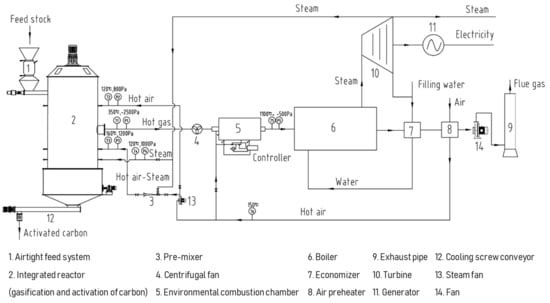
Figure 1.
A schematic diagram of the gasification system.
2.2. The Key Features
Compared to the traditional biomass gasification system, the main advantages of our new technology are summarized below.
As mentioned before, one of the barriers in developing (especially commercializing) a biomass gasification technology is the tar issue. Considering the maturity, reliability, and complexity, the most economic approach to eliminate tarry materials in the hot flue gas is still using a water scrubbing device, inevitably generating wastewater-containing fouling and poisoning volatile organic compounds (VOCs). Industries are nowadays reluctant to use water (or oil) scrubbers because of their potential pollution to the environment [21]. To cope with the tar-related problems, the gasifier in this technology is coupled with a two-stage combustor which burns the “dirty syngas” directly from the gasifier outlet without the need for gas cleaning.
The main product from traditional gasification technologies is just the syngas with ash/slag as byproducts and the contaminated water as waste. This technology system aims to produce solid char/partially activated carbon as one of its main outputs, which has greatly increased the economic viability and operation stability of the whole system. This system is actually a combination of gasification to produce syngas and carbonization to produce biochar.
The N-containing species in the volatiles are usually oxidized into Nox in a conventional combustion system. The utilization of a two-stage combustion unit has considerably enhanced the environmental performance of the gasification system. At the first stage, the hot flue gas was partially combusted in an oxygen-deficient atmosphere at a relatively low temperature, thus promoting the formation of N2 and suppressing Nox production. The second stage combustion chamber will then ensure the complete combustion of any remaining organic matter. The Nox emission level from this system is as low as 140 mg/Nm3, compared to ~250 mg/Nm3 from one-stage combustion technology.
Recuperation of heat from the tail gas to produce hot air could effectively increase the overall energy efficiency. The hot air is pumped into the gasifier via multiple inlets to initiate the char-air reactions that release heat for driving endothermic char-steam reactions. The hot steam used in the gasifier was mainly coming from the combustor. To control the reaction temperatures and the product distributions, the supply of hot steam and air has been accurately controlled, which will be introduced below.
2.3. The Gasification Reactor
The most important component in a gasification system is the gasifier where the biomass is thermochemically transformed into gaseous products, as well as the biochar/partially activated carbon in this work. The reliability and product distributions of a gasifier strongly depend on the internal structure of the reactor. To efficiently convert the nut shells to combustible gas, heat and biochar (partially activated carbon), our gasifier, as shown in Figure 2, was designed and fabricated to have the following features.
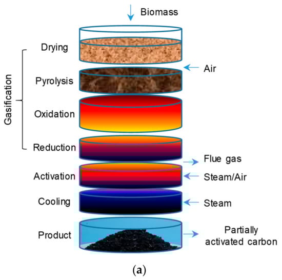
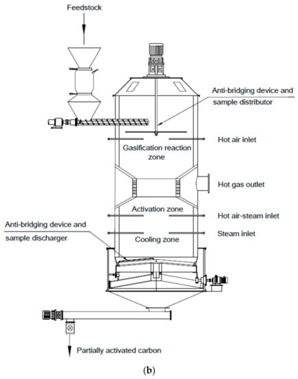
Figure 2.
The conceptual illustration (a) and the structure (b) of the commercialized gasification reactor.
(1) Sample distribution device: At the top of the gasifier, a bar installed horizontally could rotate to evenly distribute the upcoming biomass around the gasifier. At the same time, the bar could move up and down to detect the level of biomass inside the reactor, thus adjusting the biomass feeding rate.
(2) Carbon production: Different from a common gasifier that maximizes the syngas production and yields sole ash as a byproduct, our gasifier was designed to achieve a simultaneous production of biogas and biochar. Biochar is not only a valuable product, but also will play a vital role in mitigating greenhouse gas emission due to the fixation of carbon in solid state for extensive periods. Furthermore, to deliberately produce carbon as the key solid product rather than solely ash would eliminate the most fouling issues (e.g., slagging and discharging problems), which also allows the use of moderate temperatures in the gasifier.
(3) Three-stage gasifying agents supply: As shown in Figure 2a, in order to control the reaction temperature and thus the desired products, the supply of gasifying agents was separated into three stages. Air was provided to the top section to gasify the biomass and the volatiles from the initial decomposition of biomass. The air supply, at this stage, must be very carefully regulated to avoid the unexpected temperature increase. Subsequently, the pre-mixed air and steam was supplied into the middle area of the gasifier to gasify and partially activate the biochar. The dilution of air by steam demonstrated to be an effective way of controlling the reaction temperature. The third stage was called the “cooling zone”, where the retained char was further activated and cooled by reacting with steam before moving to the discharging area. The exact flow rates of air and steam were monitored and controlled by vortex flowmeters that indicate both the instantaneous flow rates and accumulative flow at all times.
(4) Char cooling and discharging device: Three ladder-shaped paddles, together with a shaft, constituted the basic structure of the rotating discharging device. On the top of the paddles, a circular stainless-steel tube with multiple holes was installed, releasing low temperature steam to further cool down the biochar (partially activated carbon). The iodine value of our biochar coming out of the gasifier was about six times of chars from other gasifiers, due to the novel arrangement of multiple reaction zones, especially the activation zone.
3. Performance at a Commercial Scale
3.1. Gasification Products and Its Durability
Figure 3 shows the syngas compositions and the operation durability for about nine months. The datum points were collected randomly when the system was continuously in operation. The CO and H2 concentrations were all between 10% and 15% by volume. The lower heating value (LHV) of product gas was generally over 4.5 MJ/Nm3. The stability of the system could also be well demonstrated by the trendline in Figure 3, although reasonable fluctuation of the system caused by the heterogeneous nature of biomass as well as inconstant feeding rate and pressure was also observed. As mentioned above, the second major product from the gasification system was solid char, which accounted for 25–30% (by mass) of the biomass feed on a dry basis. The proximate analysis (wt %) of the solid char is as follows: moisture, 0.4; volatile matter, 8.7; fixed carbon, 88.2; and ash, 3.1. The solid char partially being activated inside the gasifier with a surface area of around 500 m2/g could be further activated offline to gain commercial grade of activated carbon with surface area more than 1000 m2/g.
Figure 3.
The syngas compositions and low-heat value as a function of time.
3.2. The Energy Converting Flow from the Gasification System
The pie chart in Figure 4 clearly exhibited the typical energy flow and efficiency from our gasification system using nut shells as feedstock. Through the gasification reaction, 47% of biomass energy was transferred into syngas while 44% of the energy was still stored in solid char. The remaining 9% was in the form of hot water and heat loss. The energy converting efficiency from the syngas to electricity in this work was about 35%. Compared to other gasification technologies, the energy efficiency may not be very outstanding. Again, the key merits of this technology were its simplicity, stability, high biochar/partially activated carbon production and its environmental performance. Indeed, given the clear energy converting flow of the gasification system (thus, the product distribution), the economic advantages of this technology could be easily determined according to the prices of raw materials, operations and products (e.g., biochar and its derived products) in local markets. Currently, the economic benefit from this biomass converting system in China is about 2–3 times that of traditional thermal conversion technologies (such as combustion and pure gasification).
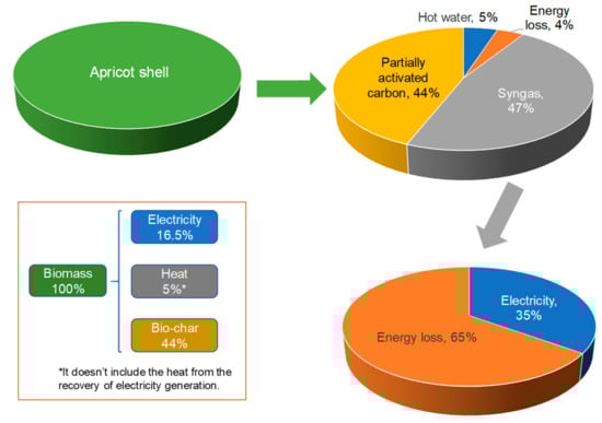
Figure 4.
The typical energy converting flow of this gasification system.
3.3. Performance of CO2 Emission
The potential excellent environmental performance is illustrated in Figure 5. It shows that 1.83 t carbon dioxide will be firstly taken from environment in order to form 1.0 t apricot kernel shell containing 50% C. When the shell is gasified, 0.88 t carbon dioxide (0.24 t carbon) will be released into atmosphere, while 0.26 t carbon will end up as solid carbon in biochar or partially activated carbon. Therefore, whenever consuming 1.0 t shell, 0.95 t carbon dioxide from air will be fixed into solid carbon, enabling the system to act as a CO2 absorber.
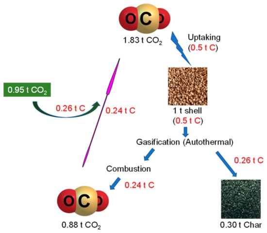
Figure 5.
A schematic diagram showing negative CO2 emission from the gasification process.
4. Conclusions
An advanced downdraft fixed-bed gasification system with integrated products of electricity, heat, and carbon has been proposed and commercialized in Chengde, China. With the specially designed internal structure inside the gasification reactor, the system could continuously operate for three years without requiring major maintenance. The difference from other gasification technologies is that this system not only produced syngas for electricity generation, but also co-produced heat and biochar (or partially activated carbon). Of these, the partially activated carbon, as one of the key outputs, has significantly benefits for the economic feasibility, as well as enabled the whole system to act as a greenhouse gas absorber.
Author Contributions
Conceptualization, J.Z.; methodology, J.Z. and S.Z.; validation, J.Z., S.Z. and H.M.; formal analysis, Y.H.; investigation, Y.Z. and H.M.; resources, J.Z.; data curation, Y.W. and S.L.; writing—original draft preparation, Y.H.; writing—review and editing, Y.H.; visualization, Y.H. and S.Z.; supervision, J.Z. and S.Z.; project administration, J.Z.; funding acquisition, J.Z., S.Z. and Y.H.
Funding
This research was funded by [National Natural Science Foundation of China] grant number [51876093] and [Start-up Fund for Scientific Research of NJFU] grant number [GXL2018033].
Acknowledgments
The authors gratefully acknowledge the financial support from National Natural Science Foundation of China (51876093) and Nanjing Forestry University (GXL2018033).
Conflicts of Interest
The authors declare no conflict of interest.
References
- Shen, Y.; Yoshikawa, K. Recent progresses in catalytic tar elimination during biomass gasification or pyrolysis—A review. Renew. Sustain. Energy Rev. 2013, 21, 371–392. [Google Scholar] [CrossRef]
- Sansaniwal, S.K.; Rosen, M.A.; Tyagi, S.K. Global challenges in the sustainable development of biomass gasification: An overview. Renew. Sustain. Energy Rev. 2017, 80, 23–43. [Google Scholar] [CrossRef]
- Feng, D.; Zhao, Y.; Zhang, Y.; Xu, H.; Zhang, L.; Sun, S. Catalytic mechanism of ion-exchanging alkali and alkaline earth metallic species on biochar reactivity during CO2/H2O gasification. Fuel 2018, 212, 523–532. [Google Scholar] [CrossRef]
- Susastriawan, A.A.P.; Saptoadi, H. Small-Scale downdraft gasifiers for biomass gasification: A review. Renew. Sustain. Energy Rev. 2017, 76, 989–1003. [Google Scholar] [CrossRef]
- Zhang, S.; Asadullah, M.; Dong, L.; Tay, H.L.; Li, C.Z. An advanced biomass gasification technology with integrated catalytic hot gas cleaning. Part II: Tar reforming using char as a catalyst or as a catalyst support. Fuel 2013, 112, 646–653. [Google Scholar] [CrossRef]
- Wang, Y.; Jiang, L.; Hu, S.; Su, S.; Zhou, Y.; Xiang, J.; Zhang, S.; Li, C.Z. Evolution of structure and activity of char-supported iron catalysts prepared for steam reforming of bio-oil. Fuel Process. Technol. 2017, 158, 180–190. [Google Scholar] [CrossRef]
- Świerczyński, D.; Libs, S.; Courson, C.; Kiennemann, A. Steam reforming of tar from a biomass gasification process over Ni/olivine catalyst using toluene as a model compound. Appl. Catal. B Environ. 2007, 74, 211–222. [Google Scholar] [CrossRef]
- Zhang, S.; Song, Y.; Song, Y.C.; Yi, Q.; Dong, L.; Li, T.T.; Zhang, L.; Feng, J.; Li, W.Y.; Li, C.Z. An advanced biomass gasification technology with integrated catalytic hot gas cleaning. Part III: Effects of inorganic species in char on the reforming of tars from wood and agricultural wastes. Fuel 2016, 183, 177–184. [Google Scholar] [CrossRef]
- Unyaphan, S.; Tarnpradab, T.; Takahashi, F.; Yoshikawa, K. An Investigation of Low Cost and Effective Tar Removal Techniques by Venturi Scrubber Producing Syngas Microbubbles and Absorbent Regeneration for Biomass Gasification. Energy Procedia 2017, 105, 406–412. [Google Scholar] [CrossRef]
- Phuphuakrat, T.; Namioka, T.; Yoshikawa, K. Absorptive removal of biomass tar using water and oily materials. Bioresour. Technol. 2011, 102, 543–549. [Google Scholar] [CrossRef] [PubMed]
- Wu, J.; Liu, Q.; Wang, R.; He, W.; Shi, L.; Guo, X.; Chen, Z.; Ji, L.; Liu, Z. Coke formation during thermal reaction of tar from pyrolysis of a subbituminous coal. Fuel Process. Technol. 2017, 155, 68–73. [Google Scholar] [CrossRef]
- Ahrenfeldt, J.; Egsgaard, H.; Stelte, W.; Thomsen, T.; Henriksen, U.B. The influence of partial oxidation mechanisms on tar destruction in TwoStage biomass gasification. Fuel 2013, 112, 662–680. [Google Scholar] [CrossRef]
- Quitete, C.P.B.; Souza, M.M.V.M. Application of Brazilian dolomites and mixed oxides as catalysts in tar removal system. Appl. Catal. A Gen. 2017, 536, 1–8. [Google Scholar] [CrossRef]
- Cao, J.P.; Liu, T.L.; Ren, J.; Zhao, X.Y.; Wu, Y.; Wang, J.X.; Ren, X.Y.; Wei, X.Y. Preparation and characterization of nickel loaded on resin char as tar reforming catalyst for biomass gasification. J. Anal. Appl. Pyrolysis 2017, 127, 82–90. [Google Scholar] [CrossRef]
- Ren, J.; Cao, J.-P.; Yang, F.-L.; Zhao, X.-Y.; Tang, W.; Cui, X.; Chen, Q.; Wei, X.-Y. Layered uniformly delocalized electronic structure of carbon supported Ni catalyst for catalytic reforming of toluene and biomass tar. Energy Convers. Manag. 2019, 183, 182–192. [Google Scholar] [CrossRef]
- Feng, D.; Zhang, Y.; Zhao, Y.; Sun, S. Catalytic effects of ion-exchangeable K+ and Ca2+ on rice husk pyrolysis behavior and its gas–liquid–solid product properties. Energy 2018, 152, 166–177. [Google Scholar] [CrossRef]
- Feng, D.; Zhao, Y.; Zhang, Y.; Zhang, Z.; Sun, S. Roles and fates of K and Ca species on biochar structure during in-situ tar H2O reforming over nascent biochar. Int. J. Hydrog. Energy 2017, 42, 21686–21696. [Google Scholar] [CrossRef]
- Wang, F.-J.; Zhang, S.; Chen, Z.-D.; Liu, C.; Wang, Y.-G. Tar reforming using char as catalyst during pyrolysis and gasification of Shengli brown coal. J. Anal. Appl. Pyrolysis 2014, 105, 269–275. [Google Scholar] [CrossRef]
- Huang, Y.; Gao, Y.; Zhou, H.; Sun, H.; Zhou, J.; Zhang, S. Pyrolysis of palm kernel shell with internal recycling of heavy oil. Bioresour. Technol. 2019, 272, 77–82. [Google Scholar] [CrossRef] [PubMed]
- Zhou, J.; Zhang, S.; Zhang, Y.; Zhang, Q.; Ma, H.; Lu, W.; Zhao, C. A downdraft gasification system for generating electricity and producing heat and activated carbon using nut biomass. Chinese Patent 105505466A, 20 April 2016. [Google Scholar]
- Koski, M.; Stedmon, C.; Trapp, S. Ecological effects of scrubber water discharge on coastal plankton: Potential synergistic effects of contaminants reduce survival and feeding of the copepod Acartia tonsa. Mar. Environ. Res. 2017, 129, 374–385. [Google Scholar] [CrossRef] [PubMed]


© 2019 by the authors. Licensee MDPI, Basel, Switzerland. This article is an open access article distributed under the terms and conditions of the Creative Commons Attribution (CC BY) license (http://creativecommons.org/licenses/by/4.0/).