Abstract
Low-temperature combustions (LTCs), such as homogeneous charge compression ignition (HCCI), could achieve high thermal efficiency and low engine emissions by combining the advantages of spark-ignited (SI) engines and compression-ignited (CI) engines. Robust control of the ignition timing, however, still remains a hurdle to practical use. A novel technology of jet-controlled compression ignition (JCCI) was proposed to solve the issue. JCCI combustion phasing was controlled by hot jet formed from pre-chamber spark-ignited combustion. Experiments were done on a modified high-speed marine engine for JCCI characteristics research. The JCCI principle was verified by operating the engine individually in the mode of JCCI and in the mode of no pre-chamber jet under low- and medium-load working conditions. Effects of pre-chamber spark timing and intake charge temperature on JCCI process were tested. It was proven that the combustion phasing of the JCCI engine was closely related to the pre-chamber spark timing. A 20 °C temperature change of intake charge only caused a 2° crank angle change of the start of combustion. Extremely low nitrogen oxides (NOx) emission was achieved by JCCI combustion while keeping high thermal efficiency. The JCCI could be a promising technology for dual-fuel marine engines.
1. Introduction
The internal combustion engine (ICE) is still the most important prime mover of vehicles and ships after more than 100 years of development. However, nowadays, it is confronted with restrictions of stringent emissions regulations and competition from electric mobility. ICEs can be separated into spark-ignited (SI) engines and compression-ignited (CI) engines. SI engines, such as gasoline engines and gas engines, usually use throttle to control intake air amount and low compression ratio to avoid knock, which produce pumping loss and low thermal efficiency. CI engines, mainly referring to diesel engines, have higher thermal efficiency than SI engines because of less pumping loss and higher compression ratio, but the NOx and soot emissions formed during high temperature diffusion combustion are the main concerns. Low-temperature combustion (LTC) modes, such as homogeneous charge compression ignition (HCCI) [1], hot premix of diesel combustion (HPDC) [2], partial premixed combustion (PPC) [3], and reactivity-controlled compression ignition (RCCI) [4,5,6], potentially offer ICEs low emissions and high thermal efficiency through lean charge combustion and low heat loss. Various fuels have been used in the research on LTC [7,8,9,10]. The common characteristics of these LTCs are the compression ignition of premixed charge and the ignition timing determined by chemical kinetics of the charge. Because the ignition timing is decoupled from the fuel injection and subject to factors of intake air temperature and pressure, fuel property and fuel-air mixture spatial distribution, the effective and accurate control of engine ignition timing is still the main hurdle to practical use. EGR (Exhaust Gas Recirculation) was widely used in LTC modes to retard ignition timing and control heat release rate. However, the transient response of EGR is not adequate for real-time ignition timing control because the EGR path is long and the EGR temperature stability is problematic, so EGR has to be combined with other technology for ignition timing control [11,12]. Technics of fast thermal management [13,14], variable compression ratio [14], fuel ratio and injection timing [15,16,17,18,19] were employed to control the ignition timing. However, costly cylinder pressure feedback was usually needed to control combustion phasing on a cycle-by-cycle basis [20]. Otherwise, the transient response could not be guaranteed because the in-cylinder thermodynamic condition was hard to estimate due to factors including engine thermal inertia and turbo charger lag.
Jet-controlled compression ignition (JCCI) was proposed to solve the above issue by the authors. In JCCI combustion mode, the ignition of premixed charge in cylinder is triggered directly by the jet. The jet could be a high temperature jet issued from a pre-chamber or high-pressure air jet or even diesel fuel jet [21,22,23,24]. In the thermal and chemical effects of the jet, the in-cylinder lean mixture ignites spontaneously. In this paper, the research focuses on pre-chamber hot jet JCCI. The working process is as follows: First, the engine has a small pre-chamber in which natural gas is fed independently, and main chamber diesel fuel and air mixture is formed by in-cylinder early injection during compression stroke; second, the engine effective compression ratio is low enough that only low temperature exothermic reaction will happen [6,25]; third, pre-chamber gas mixture is ignited by spark plug at close to compression top dead center (TDC), and hot flame jet formed leads to the onset of ignition of main chamber mixture. Murase and Hanada [26] had proposed similar pulsed flame jet (PFJ) to control the start of HCCI combustion, but the research was only performed on a rapid compression machine. The JCCI combustion needs both natural gas and diesel as fuel, so it could be applied to dual-fuel engines, especially in partial load conditions. Throttleless lean combustion could be realized by JCCI and high engine thermal efficiency and low NOx emission could be achieved.
It should be noted that the JCCI process is different from that of other pre-chamber type engines in which the combustion process is flame propagation in the cylinder [27]. For JCCI, diesel fuel is used for the main chamber. The fuel and air mixture is lean beyond flame propagation limit, and the combustion process is more like auto ignition reaction zone propagation in the charge after low-temperature oxidation [28]. Diesel fuel has a two-stage-ignition property, which could lead to more stable late-cycle auto ignition [29]. By retarding the auto ignition timing properly, in-cylinder peak pressure rise rate could be reduced due to the piston expansion, so engine mechanical stress could be alleviated, and higher load could be realized.
This study aims to investigate the combustion and emissions characteristics of the JCCI engine. The specific objectives are to verify the JCCI principle on the test engine and determine the effects of pre-chamber spark timing on main chamber ignition control and combustion process. Furthermore, robust control of the JCCI process under different intake charge temperatures is proven.
2. Experimental Methods
2.1. Engine Specifications
Experiments were done on a modified 8-cylinder marine diesel engine with only one cylinder activated and other cylinders motored. The detailed engine specifications are tabulated in Table 1. To realize JCCI combustion, a pre-chamber assembly with spark plug and gas fuel injector integrated was designed, and the assembly used for test is shown in Figure 1. The pre-chamber assembly mounting layout in the cylinder head is shown in Figure 2. The pre-chamber assembly consisted of an upper part and a lower part. The lower part with a 3 mm diameter orifice was flush mounted in the periphery of the cylinder head. The orifice axis was orientated toward the engine cylinder axis, and the include angle between the two axes was 45°. There was a sealing washer between the lower part and the upper part. The upper part with external thread was screwed into the pre-chamber mounting hole and pushed onto the sealing washer. A spark plug was installed in the upper part, and the spark plug electrode protrusion length could be changed by modifying the upper part height. A CH4 feeding tube was mounted beside the spark plug, and the CH4 metering valve was modified from a gasoline direct injection (GDI) injector. A very compact pressure sensor was also installed in the upper part to acquire the pre-chamber combustion pressure. Diesel and air pre-mixture was prepared by in-cylinder direct injection by a common rail injector with V-type intersecting holes nozzle [30]. The nozzle had six pair of holes and each pair of them comprised two sub holes of 0.14 mm intersecting at the outer surface of the nozzle with 40° angle. The intersecting holes structure is shown in Figure 3. It can enlarge fuel spray spatial distribution and significantly improve fuel atomization, especially under low ambient pressure. The spray included angle formed is about 90° so that the fuel can be kept within the piston cavity when injection advanced angle was less than 75° CA (Crank Angle) before top dead center (BTDC). In addition to low geometric compression ratio of 12, the Miller cycle was employed by retarding the intake valve close timing to 73.5° CA BTDC to avoid too early compression ignition. Compressed air from a buffer tank was used to simulate turbo-charged intake, and the air temperature was controlled by a heat exchanger. Engine exhaust was throttled by a back-pressure valve to maintain an equivalent pressure as before the turbo charger.

Table 1.
Engine specifications.
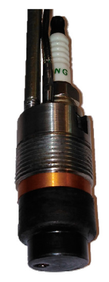
Figure 1.
Pre-chamber assembly used for test.
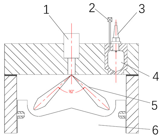
Figure 2.
Schematic of jet-controlled compression ignition (JCCI) combustion system. (1) diesel injector, (2) CH4 metering valve, (3) spark plug, (4) pre-chamber, (5) diesel spray, (6) piston.
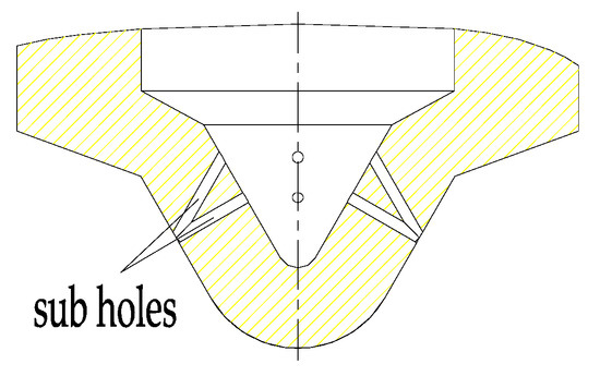
Figure 3.
V-type intersecting holes nozzle structure.
2.2. Instrumentations and Calculations
The main chamber pressure and pre-chamber pressure were measured individually by two Kistler 6054 piezoelectric sensors. The pressure signals were processed by a Kistler SCP amplifier, and the pressure data were recorded at 0.5° CA resolution by National Instruments Combustion Analysis System (CAS). Ensemble average pressure data of 100 cycles were post-processed using a first order Savitzky–Golay filter for further analysis and calculation. The apparent heat release rate (AHRR) is calculated by single-zone dual-transducer method as:
where and are the main chamber and pre-chamber pressures pegged using synchronous manifold absolute pressure measured at intake stroke bottom dead center (BDC), is the main chamber volume, is the pre-chamber volume and is the ratio of specific heats.
Combustion phasing angles of 10%, 50% and 90% of heat release (CA10, CA50 and CA90) are determined by integrating the AHRR. Crank angles between CA10 and CA90 (CA10–90) are calculated to analyze combustion duration. The main chamber diesel fuel mass flow rate was measured by an Emerson CFM Coriolis flow meter with a ±0.25% of rate precision. The pre-chamber CH4 flow rate was calculated based on injection pulse width and gas fuel valve calibration curve. Indicated thermal efficiency (ITE) is calculated:
where is the gross indicated work, and are the diesel mass injected per cycle and the lower heat value of diesel, and are the CH4 mass injected per cycle and the lower heat value of CH4.
Ringing intensity (RI) is chosen as the combustion noise metric and calculated as [31]:
where is the maximum pressure rise rate, is the maximum main chamber pressure, is the gas constant, is the maximum mass average temperature, is taken as a constant of 0.05. The RI limit was set to 5 during engine test.
The exhaust gas emissions were measured by Horiba MEXA 7100D/EGR analyzer which was manufactured by Horiba Instruments Inc. in Japan. The NOx emission was measured in NO mode. The engine and instruments set-up schematic is depicted in Figure 4.
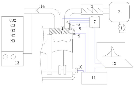
Figure 4.
Schematic of engine and instruments set-up. (1) air compressor, (2) buffer tank, (3) heat exchanger, (4) diesel injector, (5) CH4 metering valve, (6) spark plug, (7) ECU (Electronic Control Unit), (8) pre-chamber pressure sensor, (9) main chamber pressure sensor, (10) crank encoder, (11) combustion analysis system (CAS), (12) computer, (13) exhaust analyzer, (14) back pressure valve.
2.3. Experimental Procedure
Experiments were performed at mode 4 and mode 3 operating points according to ISO 8178-4 E3 cycle. The engine operating conditions are shown in Table 2. The engine speed was controlled by an AC dynamometer to set point. The engine was motored by the dynamometer under misfire conditions. The coolant outlet temperature was fixed at 85 °C. The intake temperature of the engine manifold was controlled by an intercooler and could vary from 50 °C to 90 °C.
Table 2.
Engine operating conditions.
The research consists of three experiments. First, the engine was operated respectively with and without CH4 injection and spark ignition in mode 4 and mode 3 as listed in Table 2 to verify the JCCI principle. Second, the spark timing was swept from 15° CA BTDC to top dead center (TDC) in operating mode 3 with 70 °C intake manifold air temperature to determine the effects on main chamber ignition control and combustion process. Finally, intake manifold air temperature was varied from 60 °C to 80 °C in operating mode 3 to prove the control robustness of JCCI process.
3. Results and Discussion
3.1. JCCI Principle Verification
The engine realized JCCI process at mode 4 operating point when CH4 feeding and spark in pre-chamber were employed. The PC (pre-chamber) and MC (main chamber) cylinder pressures and total AHRR calculated accordingly under different intake manifold air temperature are shown in Figure 5. The spark timing was fixed at 15° CA BTDC for all the three cases. The PC pressure curves have two humps. The first one occurs just after the spark ignition. It is caused by CH4 and air mixture combustion and heat release inside PC. After peak of the first hump, PC pressure drops as the incomplete combustion mixture busts into the MC and forms hot jet. Spontaneous mass combustion of the diesel fuel and air pre-mixture inside MC is triggered by the hot jet. The MC pressure increases quickly and exceeds PC pressure. Then the PC pressure increases along with MC pressure and forms the second hump as the MC mixture flows into the PC. The AHRR of both chambers together has only one hump, which is different from the heat release of conventional diesel diffusion combustion and indicates that premixed combustion is realized. The AHRR under higher intake manifold temperature is quicker and the peak is higher due to higher reaction speed of the mass pre-mixture in MC.
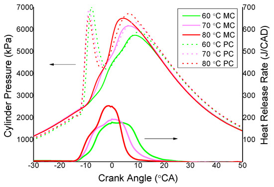
Figure 5.
Cylinder pressures and apparent heat release rate (AHRR) of JCCI at mode 4 operating point.
The engine was then operated in the same condition as above but without PC CH4 feeding and spark. The engine was dragged by the dynamometer in this case. As shown in Figure 6, the cylinder pressure and AHRR curves are quite different from the ones in Figure 5. The cylinder pressure of both chambers with 60 °C and 70 °C intake manifold temperature is close to the compression and expansion curves without combustion. Only a small amount of heat release occurs around TDC, which should be caused by low temperature reaction of the diesel and air pre-mixture. The low temperature heat release phasing advances as intake manifold temperature increases. When intake manifold temperature increases to 80 °C, the low temperature heat release phasing advances further, and a bigger amount of heat release occurs after TDC. The later heat release is caused by high temperature reaction, and it leads to MC and PC cylinder pressure rises.
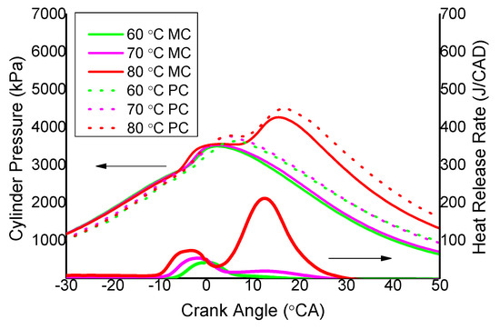
Figure 6.
Cylinder pressures and AHRR of without PC jet at mode 4 operating point.
At mode 3 operating point, the engine realized JCCI process successfully with CH4 feeding and spark in PC. The intake manifold temperature was fixed at 70 °C in the case. The MC and PC pressures and the heat release curves with different spark timing are shown in Figure 7. Similar to mode 4 JCCI process, the PC pressure curves have two humps except for the 0° CA spark timing case. The first hump is caused by the CH4 and air mixture combustion in PC, and the second hump is caused by the diesel and air pre-mixture combustion in MC. The second hump is very small in the 0° CA spark timing case because the MC combustion phasing is too late, and the PC pressure is always higher than MC pressure. It can be seen from the heat release curves that there is a small peak at the beginning of the whole heat release. It is caused by the CH4 and air mixture combustion inside of PC and hot jet ignited diesel and air pre-mixture combustion inside of MC. The small peak becomes higher as the spark timing retards because the low temperature reaction of the diesel and air pre-mixture inside MC has generated more heat release.
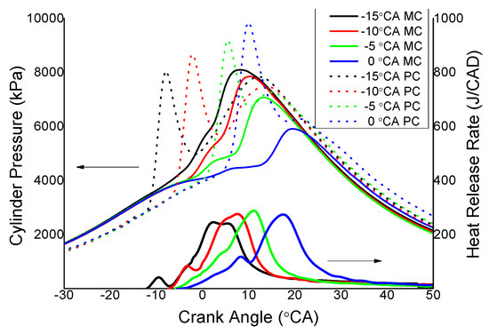
Figure 7.
Cylinder pressures and AHRR of JCCI at mode 3 operating point.
The engine cylinder pressures and heat release curves when running without CH4 feeding and spark in PC are shown in Figure 8. There is only low temperature heat release occurring around TDC for all the cases. The high temperature heat release, like in mode 4 with 80 °C intake manifold temperature, does not happen. The reason is that the engine speed is higher, and the piston moves down faster in mode 3, and the cylinder temperature decreases soon during expansion stroke, so the high temperature heat release is suppressed.
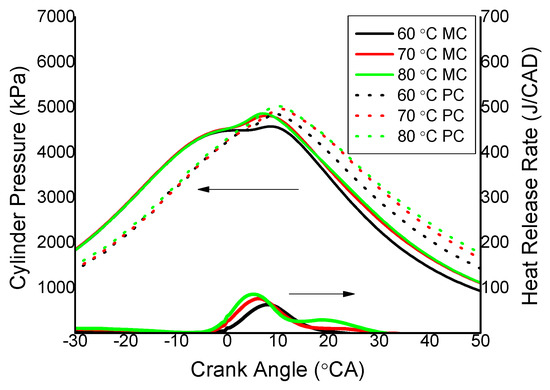
Figure 8.
Cylinder pressures and AHRR of without PC jet at mode 3 operating point.
The JCCI principle was verified based on the test results analysis above. High temperature heat release of the diesel and air pre-mixture with proper phase would not occur without PC ignition. When there was ignition and combustion inside PC, the hot jet formed consequently could quickly induce the high temperature heat release of the MC pre-mixture, so JCCI process could be realized.
3.2. JCCI Combustion Phasing Control
The mode 3 test above indicated that JCCI process was controlled effectively by the PC spark ignition and the hot jet generated consequently. The heat release phasing was close related to the spark timing. Taking CA10 and CA10–90 as the indexes of combustion starting phase and combustion duration, as can be seen in Figure 9, the CA10 phase retards from −2° CA to 7° CA when the spark timing changes from −15° CA to 0° CA, and they have basically a linear correlation. The CA50 phase and CA90 phase retard as well, but the CA50 phase retarding magnitude increases and the CA90 phase retarding magnitude decreases when the spark timing approaches 0° CA. The combustion duration of CA10–90 prolongs when spark timing changes from −15° CA to −5° CA, and it remains the same with spark timings ranging from −5° CA to 0° CA. Earlier spark timing away from TDC could generate hot jet from the PC and induce the MC mixture ignition earlier, which coupling with the cylinder compression speeds up the combustion of MC pre-mixture. Shorter combustion duration and quicker heat release lead to increasing RI. The RI with −15° CA spark timing is 4.6 MW/m2 when the CA50 is 5° CA. These RI and CA50 values are in the same level with the experimental data (with equivalence ratio of 0.4 and Pin = 1.8 bar and engine speed 1800 RPM) of Saxena et al. [14].
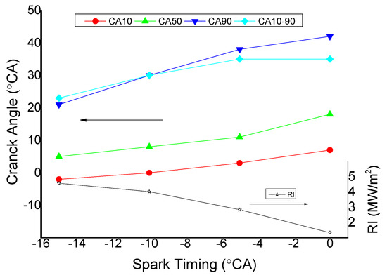
Figure 9.
Combustion phasing and ringing intensity (RI) with different spark timing.
The indicated thermal efficiency and indicated specific NO (ISNO) emission of the mode 3 test are shown in Figure 10. The ITE increases with spark timing advancing. ITE of 45.7% is achieved with −15° CA spark timing. Under this condition, the CA50 phase is 5° CA and the CA10–90 is 23° CA, as shown in Figure 9. Combustion phase center closer to TDC and shorter combustion duration contribute to the higher ITE. Compared with the experimental results of Saxena et al. [14], the correlation between ITE and spark timing and CA50 phase is quite consistent, but the ITE is higher by 16 percentage points. The reason might be that higher load (IMEP = 1000 kPa) achieved in this work has relatively low heat loss. The ITE of 45.7% achieved in this work is lower than the simulation results of Nieman et al. [16], who used natural gas and diesel as RCCI fuels and achieved ITE above 50%. To realize high load JCCI combustion, the test engine compression ratio was reduced to 12, which was much lower than that of Nieman simulation (compression ratio of 16.1) and was the main reason for lower ITE. Extremely low NO emission is realized by JCCI premixed combustion. The highest NO emission with −15° CA spark timing is only 0.25 g/kWh. The NOx emission (of which more than 95% is NO) without any after treatment can meet IMO Tier III regulation [32]. Figure 11 shows the indicated specific HC (ISHC) and CO (ISCO) emissions. The ISHC emission is below 1 g/kWh with spark timing from −15° CA to 0° CA, and it decreases very slightly with spark timing advancing. It is thought that the HC emission is formed mainly from unburned fuel film attached to combustion chamber wall. The fuel spray from the V-type intersecting holes nozzle distributes mainly in the piston cavity and evaporates quickly with finer droplets, so low HC emission could be achieved. The CO emission decreases significantly with spark timing advancing, and it achieves 6.96 g/kWh at −15° CA. The low premixed combustion temperature leads to incomplete oxidation of CO, which is responsible for the high CO emission level.
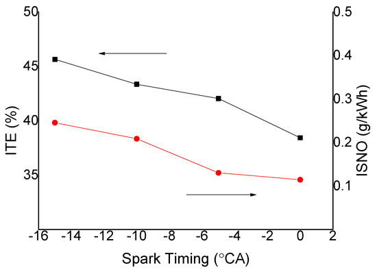
Figure 10.
Indicated thermal efficiency (ITE) and indicated specific NO (ISNO) with different spark timing at mode 3 operating point.
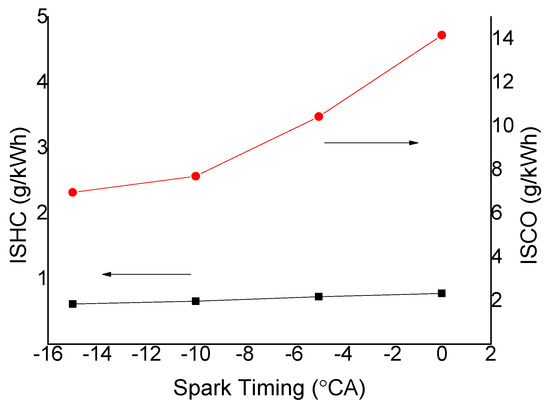
Figure 11.
Indicated specific HC (ISHC) and indicated specific CO (ISCO) with different spark timing at mode 3 operating point.
3.3. Effect of Intake Temperature on JCCI Combustion
Premixed compression ignition process is dominated by chemical dynamics, so the ignition timing is sensitive to pre-mixture thermal conditions. The JCCI combustion utilizes hot jet to trigger onset of ignition, which makes it more robust. Figure 12 shows the combustion phases and RI with spark timing of −15° CA at different intake manifold air temperatures at mode 3 operating point. When the intake manifold air temperature rises from 60 °C to 80 °C, the CA10 changes from −1° CA to −3° CA, while the CA50 changes from 4° CA to 11° CA and the CA90 changes from 13° CA to 27° CA. The intake manifold air temperature change has bigger influence on the combustion duration than on the start of combustion. The start of combustion still relates closely to the spark ignition in PC and the hot jet issued to MC. The higher intake air temperature could speed up the pre-mixture reaction, but too early high temperature mass heat release could be avoided, up to 80 °C intake air temperature. The low temperature reaction of diesel pre-mixture at the moment of PC hot jet issuing is more complete, so the combustion progress followed is more rapid at the onset of ignition. The RI increases to 5.8 MW/m2 at intake air temperature of 80 °C, and the audible combustion noise is sharper.
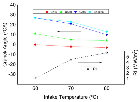
Figure 12.
Combustion phases and RI at different intake temperatures.
The ITE and emissions of NO, HC and CO are shown in Figure 13 and Figure 14. The ITE and NO emission increase with temperature rising, while the HC and CO emissions decrease with temperature rising. High ITE of 47.1% is achieved at intake air temperature of 80 °C, which is a consequence of shorter CA10–90, as shown in Figure 12. The HC emission decreases from 1.04 g/kWh to 0.61 g/kWh when intake temperature rises from 60 °C to 70 °C and decreases to 0.58 g/kWh when intake temperature rises to 80 °C. The CO emission decreases from 8.34 g/kWh to 6.96 g/kWh and 5.56 g/kWh when intake temperature rises from 60 °C to 70 °C and 80 °C. The CO emission is sensitive to intake temperature and resulting combustion temperature, which is important for CO oxidation. The HC emission is less sensitive to intake temperature because some HC is generated in the dead zones including space between cylinder liner and piston above first ring. The JCCI combustion process is more rapid and complete under higher intake air temperature condition. However, the resulting higher RI has a negative impact on the engine durability, and it should be checked by further tests.
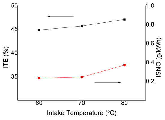
Figure 13.
ITE and ISNO at different intake temperatures.
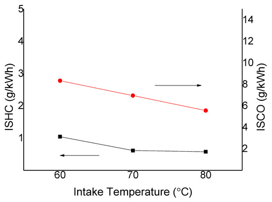
Figure 14.
ISHC and ISCO at different intake temperatures.
4. Conclusions
The present work has researched the characteristics of hot jet JCCI combustion process in a modified marine engine fueled with diesel and CH4. By introducing a PC with additional gas fuel feeding and spark ignition, the compression ignition of MC diesel and air pre-mixture is controlled effectively by the hot jet issued from the PC at low- and medium-load operating points. The mechanism of such JCCI is that the PC hot jet rich in radicals could trigger the high temperature reaction of the diesel and air pre-mixture during low temperature reaction phase.
In the experiments, the combustion phasing is related closely to the PC spark timing. The CA10 phase changes almost linearly with the spark timing. Earlier spark timing results in shorter combustion duration and higher ITE. ITE of 45.7% and NO emission of 0.25 g/kWh is achieved with −15° CA spark timing at medium load point of 1000 kPa IMEP. The HC and CO emissions decrease with spark timing advancing, however the CO emission is still high with −15° CA spark timing because the premixed combustion temperature is too low for CO oxidization. Considering that the NOx emission is much lower than the regulation limit, and the ITE could still be improved further, the engine compression ratio and PC spark timing need to be optimized further in future research.
The JCCI combustion shows robust control of combustion phasing under different intake air temperature conditions. The CA10 changes by only 2° CA when the intake manifold air temperature rises from 60 °C to 80 °C. Higher ITE and lower HC and CO emissions could be achieved with higher intake air temperature because of shorter combustion duration and higher combustion efficiency. However, the RI increases as well with higher intake air temperature, and the impact on engine durability should be checked further.
The characteristics of high thermal efficiency and extremely low NO emission of JCCI combustion make it promising for marine engines. The engine could operate in JCCI mode at low- and medium-load conditions to meet the IMO Tier III NO emission regulations with good economy and switch to lean burn gas engine mode at high load conditions to meet the power and emission requirements.
Author Contributions
Conceptualization and funding acquisition, W.L.; methodology, investigation and writing—original draft preparation, H.T.; software, H.T. and T.Y.; validation, J.C. and J.T.; writing—review and editing, Y.F.
Funding
This work was supported by High Technology Ship Program by the Ministry of Industry and Information Technology of China.
Conflicts of Interest
The authors declare no conflict of interest.
Nomenclature
| LTC | Low Temperature Combustion |
| HCCI | Homogeneous Charge Compression Ignition |
| SI | Spark Ignited |
| CI | Compression Ignited |
| JCCI | Jet Controlled Compression Ignition |
| NOx | Nitrogen Oxides |
| ICE | Internal Combustion Engine |
| HPDC | Hot Premix of Diesel Combustion |
| PPC | Partial Premixed Combustion |
| RCCI | Reactivity Controlled Compression Ignition |
| EGR | Exhaust Gas Recirculation |
| TDC | Top Dead Center |
| PFJ | Pulsed Flame Jet |
| GDI | Gasoline Direct Injection |
| CA | Crank Angle |
| BTDC | Before Top Dead Center |
| ATDC | After Top Dead Center |
| CAS | Combustion Analysis System |
| ECU | Electronic Control Unit |
| AHRR | Apparent Heat Release Rate |
| BDC | Bottom Dead Center |
| ITE | Indicated Thermal Efficiency |
| RI | Ringing Intensity |
| IMEP | Indicated Mean Effective Pressure |
| PC | Pre-Chamber |
| MC | Main Chamber |
| ISNO | Indicated Specific NO |
| ISHC | Indicated Specific HC |
| ISCO | Indicated Specific CO |
References
- Thring, R.H. Homogeneous Charge Compression Ignition (HCCI) Engines. In Proceedings of the 1989 SAE International Fall Fuels and Lubricants Meeting and Exhibition, Baltimore, MD, USA, 25–28 September 1989. [Google Scholar]
- Hu, G. New Strategy on Diesel Combustion Development. In Proceedings of the SAE International Congress & Exposition, Detroit, MI, USA, 26 February–2 March 1990. [Google Scholar]
- Noehre, C.; Andersson, M.; Johansson, B.; Hultqvist, A. Characterization of Partially Premixed Combustion. In Proceedings of the Powertrain & Fluid Systems Conference & Exhibition, Toronto, ON, Canada, 16–19 October 2006. [Google Scholar]
- Kokjohn, S.; Hanson, R.; Splitter, D.; Reitz, R. Experiments and Modeling of Dual-Fuel HCCI and PCCI Combustion Using In-Cylinder Fuel Blending. SAE Int. J. Engines 2010, 2, 24–39. [Google Scholar] [CrossRef]
- Kokjohn, S.; Hanson, R.; Splitter, D.; Reitz, R. Fuel reactivity controlled compression ignition (RCCI): A pathway to controlled high-efficiency clean combustion. Int. J. Eng. Res. 2011, 12, 209–226. [Google Scholar] [CrossRef]
- Saxena, S.; Bedoya, I.D. Fundamental phenomena affecting low temperature combustion and HCCI engines, high load limits and strategies for extending these limits. Prog. Energy Combust. Sci. 2013, 39, 457–488. [Google Scholar] [CrossRef]
- Liu, H.; Yao, M.; Zhang, B.; Zheng, Z. Influence of Fuel and Operating Conditions on Combustion Characteristics of a Homogenous Charge Compression Ignition Engine. Energy Fuels 2009, 23, 1422–1430. [Google Scholar] [CrossRef]
- Shi, L.; Qu, S.; Gui, Y.; Deng, K. Combustion and emission characteristics of diesel partial homogeneous charge compression ignition (p-HCCI) by adding fuel injection in negative valve overlap. Energy Fuels 2009, 23, 4966–4973. [Google Scholar] [CrossRef]
- Yang, D.B.; Wang, Z.; Wang, J.X.; Shuai, S. Experiment and chemical kinetics analysis of active atmosphere with different fuels in HCCI combustion. Energy Fuels 2010, 24, 4872–4878. [Google Scholar] [CrossRef]
- Li, Y.; Jia, M.; Chang, Y.; Xie, M.; Reitz, R.D. Towards a comprehensive understanding of the influence of fuel properties on the combustion characteristics of a RCCI (reactivity controlled compression ignition) engine. Energy 2016, 99, 69–82. [Google Scholar] [CrossRef]
- Iwabuchi, Y.; Kawai, K.; Shoji, T.; Takeda, Y. Trial of New Concept Diesel Combustion System-Premixed Compression-Ignited Combustion-. SAE Trans. 1999, 108, 142–146. [Google Scholar]
- Kodama, Y.; Nishizawa, I.; Sugihara, T.; Sato, N.; Iijima, T.; Yoshida, T. Full-Load HCCI Operation with Variable Valve Actuation System in a Heavy-Duty Diesel Engine. In Proceedings of the SAE 2007 World Congress, Detroit, MI, USA, 16–19 April 2007. [Google Scholar]
- Haraldsson, G.; Tunestål, P.; Johansson, B. Transient Control of a Multi Cylinder HCCI Engine During a Drive Cycle. In Proceedings of the SAE 2005 World Congress & Exhibition, Detroit, MI, USA, 11–14 April 2005. [Google Scholar]
- Saxena, S.; Chen, J.-Y.; Dibble, R. Maximizing Power Output in an Automotive Scale Multi-Cylinder Homogeneous Charge Compression Ignition (HCCI) Engine. In Proceedings of the SAE 2011 World Congress & Exhibition, Detroit, MI, USA, 12–14 April 2011. [Google Scholar]
- Dempsey, A.B.; Walker, N.R.; Reitz, R.D. Effect of Piston Bowl Geometry on Dual Fuel Reactivity Controlled Compression Ignition (RCCI) in a Light-Duty Engine Operated with Gasoline/Diesel and Methanol/Diesel. SAE Int. J. Engines 2013, 6, 78–100. [Google Scholar] [CrossRef]
- Nieman, D.E.; Dempsey, A.B.; Reitz, R.D. Heavy-Duty RCCI Operation Using Natural Gas and Diesel. SAE Int. J. Engines 2012, 5, 270–285. [Google Scholar] [CrossRef]
- Lim, J.H.; Reitz, R.D. High Load (21Bar IMEP) Dual Fuel RCCI Combustion Using Dual Direct Injection. In Proceedings of the ASME 2013 Internal Combustion Engine Division Fall Technical Conference, Dearborn, MI, USA, 13–16 October 2014. [Google Scholar]
- Najt, P.M.; Foster, D.E. Compression-Ignited Homogeneous Charge Combustion. In Proceedings of the SAE International Congress & Exposition, Detroit, MI, USA, 28 February–4 March 1983. [Google Scholar]
- Wissink, M.; Reitz, R.D. Direct Dual Fuel Stratification, a Path to Combine the Benefits of RCCI and PPC. SAE Int. J. Engines 2015, 8, 878–889. [Google Scholar] [CrossRef]
- Arora, J.K.; Shahbakhti, M. Real-Time Closed-Loop Control of a Light-Duty RCCI Engine During Transient Operations. In Proceedings of the SAE World Congress Experience, Detroit, MI, USA, 4–6 April 2017. [Google Scholar]
- Zhang, Q.; Long, W.; Tian, J.; Wang, Y.; Meng, X. Experimental and numerical study of jet controlled compression ignition on combustion phasing control in diesel premixed compression ignition systems. Energies 2014, 7, 4519–4531. [Google Scholar] [CrossRef]
- Long, W.; Meng, X.; Tian, J.; Tian, H.; Cui, J.; Feng, L. Effects of air jet duration and timing on the combustion characteristics of high-pressure air jet controlled compression ignition combustion mode in a hybrid pneumatic engine. Energy Convers. Manag. 2016, 127, 392–403. [Google Scholar] [CrossRef]
- Meng, X.; Zuo, M.; Long, W.; Tian, J.; Tian, H. Investigation of Effects of Air Jet Pressure and Temperature on High-Pressure Air Jet Controlled Compression Ignition Combustion Based on a Novel Thermodynamic Cycle. Energy Fuels 2016, 30, 674–683. [Google Scholar] [CrossRef]
- Long, W.; Li, B.; Cao, J.; Meng, X.; Tian, J.; Cui, J.; Tian, H. Effects of dual-direct injection parameters on performance of fuel Jet Controlled Compression Ignition mode on a high-speed light duty engine. Fuel 2019, 235, 658–669. [Google Scholar] [CrossRef]
- Liu, Y.D.; Jia, M.; Xie, M.Z.; Pang, B. Enhancement on a skeletal kinetic model for primary reference fuel oxidation by using a semidecoupling methodology. Energy Fuels 2012, 26, 7069–7083. [Google Scholar] [CrossRef]
- Murase, E.; Hanada, K. Control of the Start of HCCI Combustion by Pulsed Flame Jet. In Proceedings of the SAE Powertrain & Fluid Systems Conference & Exhibition, San Diago, CA, USA, 21–24 October 2002. [Google Scholar]
- Toulson, E.; Schock, H.J.; Attard, W.P. A Review of Pre-Chamber Initiated Jet Ignition Combustion Systems. In Proceedings of the SAE 2010 Powertrains Fuels & Lubricants Meeting, San Diago, CA, USA, 25–27 October 2010. [Google Scholar]
- Kuwahara, K. Reaction Zone Propagation by Spark Discharge in Homogeneous Lean Charge after Low-Temperature Oxidation. In Proceedings of the SAE 2015 World Congress & Exhibition, Detroit, MI, USA, 21–23 April 2015. [Google Scholar]
- Sjöberg, M.; Dec, J.E. Comparing late-cycle autoignition stability for single- and two-stage ignition fuels in HCCI engines. Proc. Combust. Inst. 2007, 31, 2895–2902. [Google Scholar] [CrossRef]
- Dong, Q.; Long, W.; Ishima, T.; Kawashima, H. Spray characteristics of V-type intersecting hole nozzles for diesel engines. Fuel 2013, 104, 500–507. [Google Scholar] [CrossRef]
- Eng, J. Characterization of Pressure Waves in HCCI Combustion. In Proceedings of the SAE Powertrain & Fluid Systems Conference & Exhibition, San Diago, CA, USA, 21–24 October 2002. [Google Scholar]
- International Maritime Organization. Revised MARPOL Annex VI: Regulations for the Prevention of Air Pollution from Ships and NOx Technical Code 2008, 2nd ed.; IMO Publishing: London, UK, 2009; ISBN 9789280142433. [Google Scholar]
© 2019 by the authors. Licensee MDPI, Basel, Switzerland. This article is an open access article distributed under the terms and conditions of the Creative Commons Attribution (CC BY) license (http://creativecommons.org/licenses/by/4.0/).