Article

Analysis and Control of Wind Power Grid Integration Based on a Permanent Magnet Synchronous Generator Using a Fuzzy Logic System with Linear Extended State Observer

1
School of Electrical and Electronic Engineering, Tianjin University of Technology, Tianjin 300384, China
2
School of Electrical and Information Engineering, Tianjin University, Tianjin 300072, China
*
Author to whom correspondence should be addressed.
Energies 2019, 12(15), 2862; https://doi.org/10.3390/en12152862
Submission received: 28 June 2019 / Revised: 22 July 2019 / Accepted: 23 July 2019 / Published: 25 July 2019
(This article belongs to the Special Issue Control Schemes for Wind Electricity Systems)

Abstract

:
Recently, wind energy conversion systems (WECSs) have attracted attention due to their effective application in renewable energy sources. It is a complex system with multi-variables, strong coupling, non-linearity, and variable parameters; however, traditional control systems are inadequate in answering the demands of complex systems. In order to solve the complexity and improve the transient stability during grid faults and power fluctuations, this paper proposes a fuzzy logic system with the linear extended state observer (FLS-LESO) applied to WECSs based on a permanent magnet synchronous generator (PMSG). The FLS-LESO consists of a fuzzy logic controller, a conventional PD controller, and the linear extended state observer (LESO). This paper analyzes the mathematical model of a wind power system and combines it with LESO to improve the estimation accuracy of the observer and further improve the control performance. In the simulation study, the control performance of the FLS-LESO was also tested under various operating conditions using the MATLAB/Simulink simulation platform to verify the correctness and effectiveness of the control system.

1. Introduction

Because of the abundant necessity of energy harvest and continuous depletion of fossil fuels, demands of renewable energy sources are gaining more attention [1,2]. There are many methods of generating electricity from renewable sources, such as the wind turbine and solar panel. Wind turbines, which convert wind energy into electrical energy, are the most important of these methods. Many types of generator are used in wind turbines [3,4]. A permanent magnet synchronous generator (PMSG) has recently begun to attract the attention of wind turbine manufacturers due to its superior features. The PMSG is supplied to the electrical grid system by means of the grid-side converter (GSC), machine-side converter (MSC), and control systems [5,6]. The fault ride-through (FRT) capability is one of the important issues for the operation system of the wind power system [7,8,9,10]. The grid connection requirements (GCRs) involve the operational condition control of the distributed power system [11]. The GCRs have to provide efficiency and reliability to the electrical grid system. The wind turbine (WT) must remain connected to the electrical grid system during grid faults [12]. The fault ride-through is depicted in three stages [13]:
  • In the first stage, a WT constantly supplies an electrical power grid system during grid fault time or machine-side power fluctuates during grid normal time;
  • In the second stage, the machine-side power and the network side power cannot maintain the balance, the surplus energy accumulates in the DC bus and causes its voltage fluctuation;
  • In the third stage, through the output of the control system, the power of both sides of the converter is rebalanced.
All these requirements must be considered in the design of the controller and power converter of the WECS. This design increases the stability of the WECS during a grid fault [14]. Therefore, it is of great practical significance to further study the control strategy to enhance the operation performance of wind power systems when grid-side voltage changes and machine-side power fluctuates.
Many methods are proposed in the literature for the FRT capability enhancement. The peak current limitation for a high-power PMSG was realized in Reference [15]. Maximum power point tracking (MPPT) was implemented in the GSC and MSC. An active crowbar is kept the DC link voltage value by using this method [16]. A superconducting fault current limiter (SFCL) was implemented for the FRT enhancement of a PMSG in Reference [17]. However, this requires additional circuit links, which not only increases the design difficulty of WECS, but also increases the upfront investment and maintenance cost. The static synchronous compensator (STATCOM) has been implemented to analyze a dynamic mechanism for a wind farm [18]. A coordinating control system for wind turbines was presented in Reference [18]. However, STATCOM has disadvantages, such as high cost and additional hardware needs. A braking chopper (BC) system was implemented for the FRT enhancement of a PMSG in Reference [19,20,21]. The presented method achieved reductions in the fault currents in DC systems. This method has some advantages, such as low cost and a simple control structure.
Recently, soft computing methods have started to develop rapidly with the development of computer technology. Soft computing methods are applied in real-world applications, such as renewable energy and automotive and motor control. Soft computing methods are widely implemented in wind power applications, such as for maximum power point tracking (MPPT) control, pitch control, fault diagnosis, wind power integration, wind turbine power control, and prediction of wind speed and power. Soft computing methods consist of four computing algorithms such as predictive method, genetic algorithm, artificial neural networks, and fuzzy logic controllers.
The fuzzy logic controller has a number of distinguishing advantages over conventional controllers. It is not so sensitive to variations of system structure, parameters and operation points and can be easily implemented in a large-scale nonlinear system. Furthermore, the fuzzy logic controller is a sophisticated technique that is easy to design and implement. In the past decade, many researchers have attempted to combine conventional proportional plus integral plus derivative (PID) controllers with fuzzy logic to improve controller performance [22,23,24]. The fuzzy logic controller has two input signals, and the output signal of the fuzzy logic controller is the input signal of the conventional PID controller. Through fuzzy reasoning, the parameters are adjusted adaptively, and the transient process of the system is improved. But in the actual system, the derivative element is usually not used because of the noise signal. The sampling time of fuzzy controller determines the control precision. Too huge sample interval worsens the transition process, and too short sample time greatly increase the computation and input cost. In addition, the fuzzy logic control is a type of soft computing method that overcomes the uncertainties of some systems [25]. Uncertainty is a natural part of intelligent systems in many applications. However, fuzzy logic control does not fully deal with the uncertainties of intelligent systems.
The LESO can be used to solve the core problem of the uncertainties of the model and disturbance observation in reference [26]. Using the idea of state observer, the disturbance which affects the output of the controlled object is expanded into a new state variable, and a state observer which can observe the extended disturbance is established by using a special feedback mechanism. This LESO can observe disturbances and obtain estimates without relying on the perturbation generating model or direct measurement.
This paper designs a fuzzy logic system with linear extended state observer (FLS-LESO) to improve the control performance of the WECS. On the one hand, by introducing LESO to observe and compensate the disturbance, the negative effects such as slow response, easy oscillation and saturation of control quantity caused by the use of integral element are avoided. Moreover, the derivative element can be used in the system to further improve the tracking performance of the system. On the other hand, the adjustment burden of fuzzy controller is reduced by integrating some known system information into LESO. The sampling time of fuzzy controller can be increased appropriately to reduce the input cost of microcomputer. All simulation results proved that the presented a FLS-LESO has the capability to improve the FRT capability of a PMSG.

2. Wind Energy Conversion System

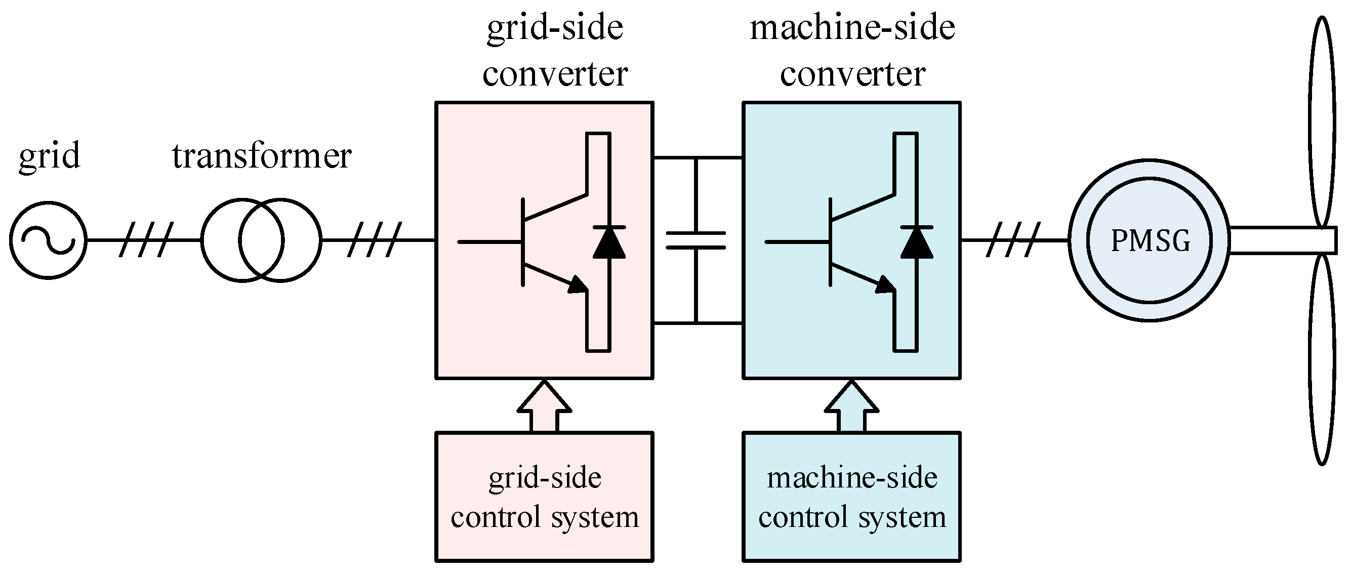
A WECS consists of a blade generator, control system, transformer, and power electronics components [27], as shown in Figure 1. Wind turbines convert wind energy into electrical energy. The direct-drive permanent magnet synchronous wind turbine is connected to the power grid through full power back-to-back converters. The machine-side converter controls the motor speed or torque to realize the maximum power tracking of wind energy [28,29]. The grid-side converter mainly stabilizes the DC bus voltage and controls the grid-connected power factor and power quality.
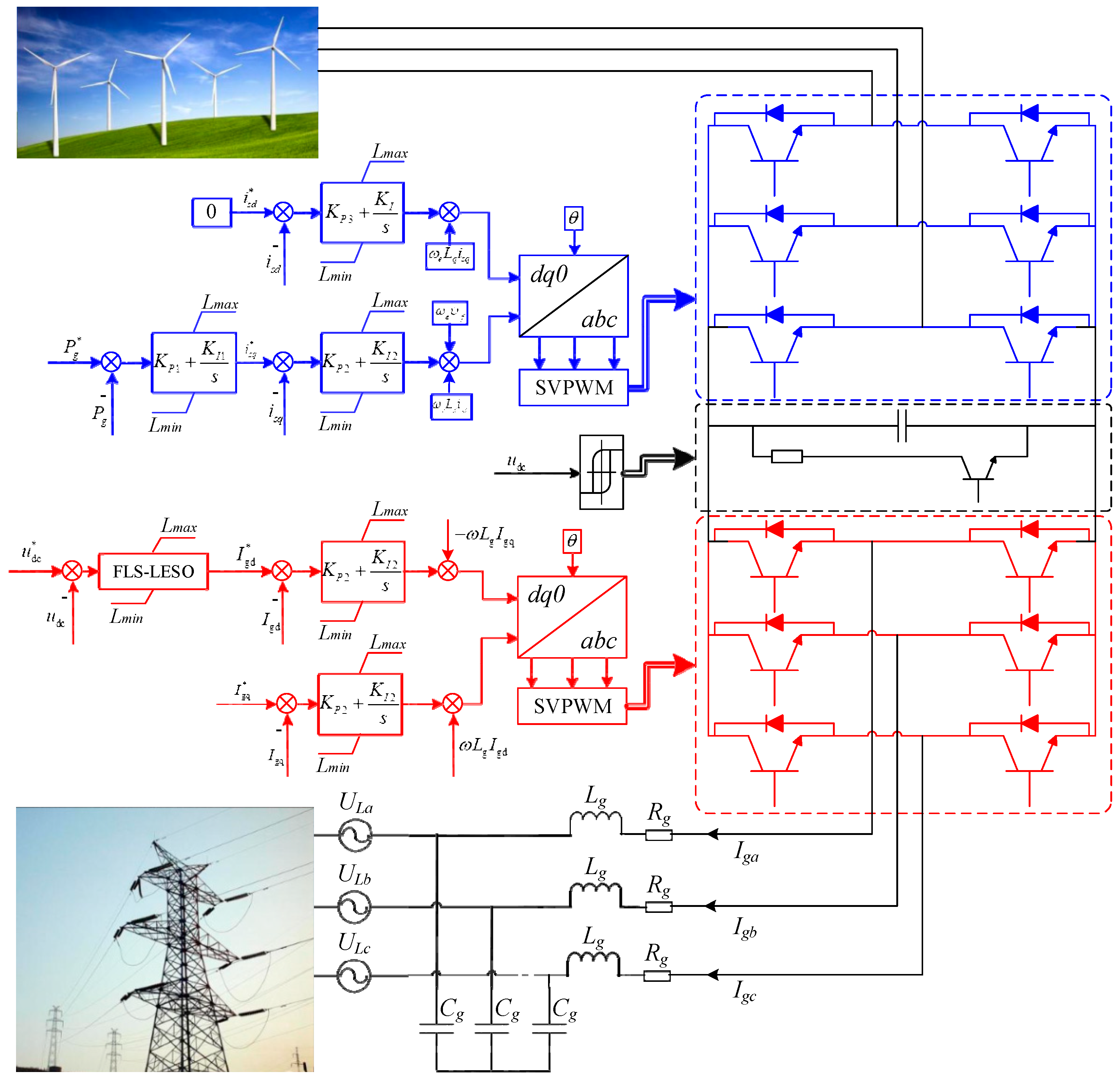
The topological structure of WECS is shown in Figure 2. The inverter circuit adopts full bridge AC/DC converter. Bidirectional switching devices use six common emitter insulated-gate bipolar transistor (IGBT) switch sequences. R g ,   L g and C g respectively represent the internal resistance, filter inductance and capacitance of the grid-side filter. The i d c is DC current and u d c is DC voltage. This system adopts the space vector modulation strategy. In order to improve disturbance immunity and meet the power quality requirements of smart grid, it is necessary to control the grid-connected inverter of wind power.
According to the topology shown in Figure 2, KVL three-phase voltage equation can be obtained [30,31,32]:
[ U g a U g b U g c ] = [ U L a U L b U L c ] + R g [ I g a I g b I g c ] + L g d d t [ I g a I g b I g c ]
where U g a ,   U g b and U g c are the inverter voltages of three-phase network side. U L a ,   U L b and U L c represent three-phase grid voltages. I g a ,   I g b and I g c depict three-phase grid-side inverter currents.
The transformation matrix from the three-phase static coordinate system to the two-phase static coordinate system is:
C 3 s / 2 s = 2 3 [ 1 1 2 1 2 0 3 2 3 2 ]
The transformation matrix from the two-phase static coordinate system to the two-phase rotating coordinate system is:
C 2 s / 2 r = 2 3 [ cos θ sin θ sin θ cos θ ]
After conversion:
[ U g d U g q ] = [ U L d U L q ] + R g [ I g d I g q ] + L g d d t [ I g d I g q ] + L g [ ω I g q ω I g d ]
where U g d and U g q are the voltages of the q and d loops in the inverter on the grid-side, respectively. The U L d and U L q depict the voltages of the d and q loops in the three-phase grid voltage, respectively. I g d and I g q represent d and q loops currents of the grid-side inverter, and ω is the electric angular of the grid. The Equation (4) shows that I g d and I g q are controlled by U g d and U g q , and are influenced by ω L g I g q and ω L g I g d , voltage drop R g I g d and R g I g q , and grid voltage U L d and U L q .
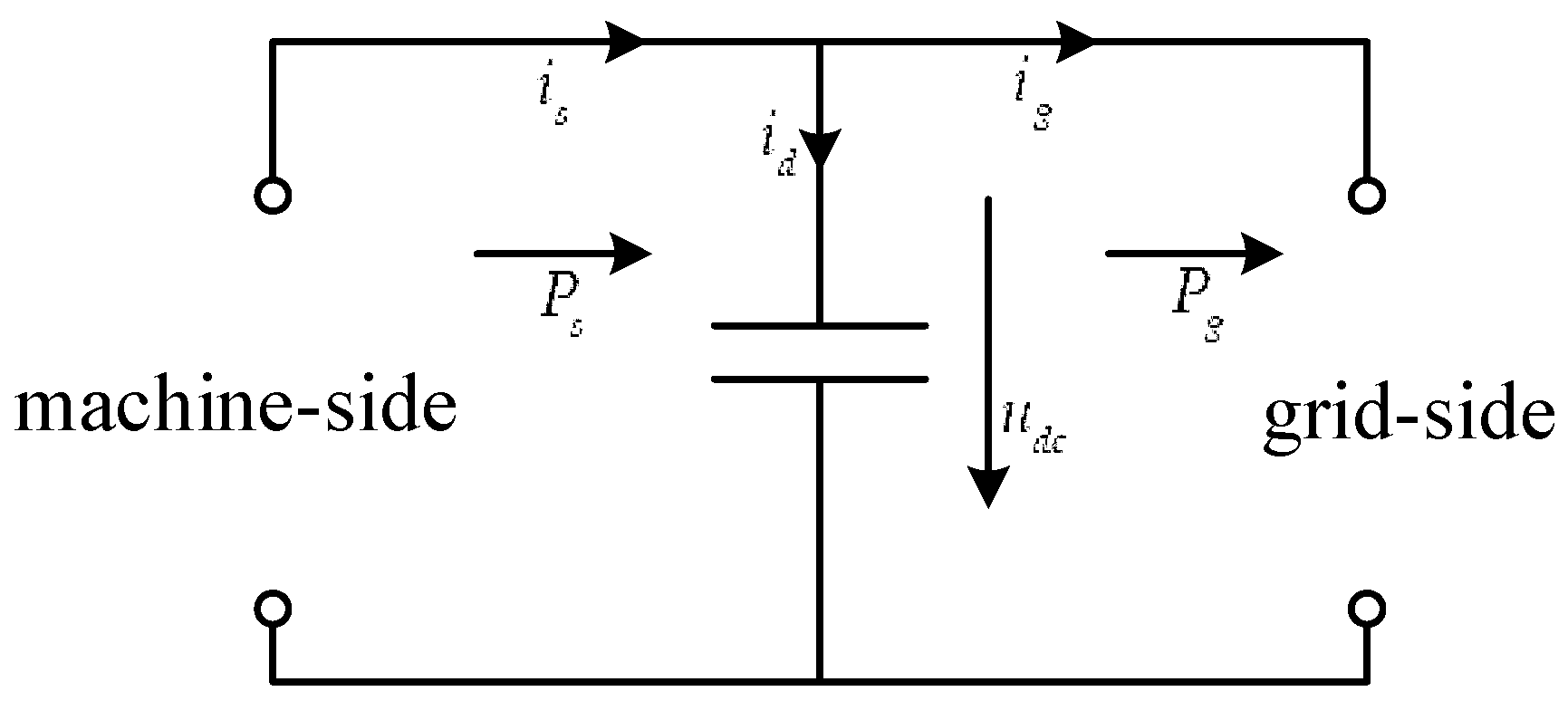
The PMSG adopts a full power converter structure to completely isolate the direct drive permanent magnet motor from the power grid. In the case of low voltage fault, it is more conducive to the stable operation of the protection system. This topology makes its FRT capability much higher than that of the doubly fed induction generator (DFIG) system. However, there are still some problems such as high DC side voltage and converter overcurrent. Grid faults will have a great impact on direct drive WECS. From the perspective of energy transmission, the transient characteristics of PMSG wind energy conversion system under the fault of instantaneous grid voltage drop are analyzed, as shown in Figure 3.
Through the machine-side converter, the permanent magnet synchronous generator (PMSG) input active power P s to the DC bus. Ignoring the machine-side converter loss, the output power of the converter is equal to that of the generator:
P s = u s d i s d + u s q i s q = u d c i s
where u s q and u s d are the voltages of the q and d loops in the stator, respectively. The voltages of the u s q and u s d are utilized to generate the reference three-phase sinusoidal voltage, and the i s d and i s q depict the currents of the d and q loops in the stator, respectively. The i s is the DC bus current of the machine-side converter, and u s d is the DC bus voltage of the DC side.
Then, the capacitive current id at the DC side is as follows:
i d = C d u d c d t = i s i g
where C is the DC bus capacitance, and i g is the DC bus current of the grid-side converter.
Ignoring the power loss of the power device, the input power of the grid-side converter is consistent with the input power of the power grid, as follows:
P g = u d c i g = u d g i d g + u q g i q g
where u d g and u q g are the voltages of the q and d loops in the grid-side, respectively. The i g d and i g q depict the currents of the d and q loops in the grid ride, respectively.
During normal operation, the power on both sides of the converter keeps balance ( P s = P g ). The u d c is stable at a certain value, as follows:
C u d c d u d c d t = u d c i s u d c i g
C u d c d u d c d t = P s P g = Δ P
According to the electrical theory, the storage energy of bus capacitor C in the intermediate DC link can is illustrated in the Equation (10), as follows:
W = 1 2 C u d c 2
Therefore, from the Equation (8), during normal operation of the power grid, Δ P is 0 and u d c is a constant value. From the Equation (7), the active power P g sent by the converter to the power grid decreases when the power grid voltage falls in fault sags. During this period, assuming that the wind speed is constant, then the active power P s emitted by the machine-side is constant. The active power generated on the machine-side cannot be transmitted to the grid in time, resulting in Δ P > 0 . From Equations (5), (7), (9) and (10), the excess energy will build up on the DC side capacitor, causing the voltage to rise and the current flowing through the bus capacitor and the grid-side converter to increase rapidly. Excessive voltage and current can damage capacitors and other devices if not handled properly. In order to avoid losses and meet the requirements of smart grid on power quality, it is necessary to control the grid-connected inverter of wind power.

3. Structures of Fuzzy Logic System with Linear Extended State Observer

3.1. Fuzzy Controller

With the complexity of the control system and the controlled object, it is manifested by strong coupling, time-varying parameters and nonlinear characteristic of the control system. The more prominent problem is that the information quantity obtained from the system object is relatively reduced, while the requirement for control performance is increasingly higher. Many times, it is difficult or impossible to establish an accurate mathematical model of the controlled object. The experience of manual control is described in language and a series of conditional statements are formed, that is, control rules. Using fuzzy theory, fuzzy language variables and fuzzy logic reasoning, the fuzzy control rules are upgraded to numerical operations, and the computer USES programs to realize these control rules. In this way, computer simulation can be used to automatically control the controlled object [22,23].
The composition of the fuzzy logic controller is shown in Figure 4, which is comprised of four main components: the fuzzification, the fuzzy inference, the knowledge base and the defuzzification [24]. In the step of input expansion and transfer, discrete input can be scaled appropriately. Fuzzification converts the exact amount of input into a fuzzy value. After fuzzy reasoning according to certain fuzzy rules, the appropriate control action is determined by querying the previously established rule table, and finally the fuzzy control quantity is transformed into the precise quantity.
The fuzzy controller can be divided into single variable fuzzy controller and multi-variable fuzzy controller. We usually use univariate fuzzy controller, which has one-dimensional, two-dimensional and multidimensional fuzzy controller. The dimension here refers to the number of input variables for the controller, as shown in Figure 5.
The one-dimensional controller is the simplest, but not widely applicable. The control rules of multidimensional controller are complex, and the algorithm is difficult to implement in engineering applications. So a two-dimensional fuzzy controller is widely used in a large number of fuzzy control systems.
In this study, a fuzzy PID controller with double input was proposed to improve the control performance of the WECS. This fuzzy PID controller is composed of a traditional PID controller and a fuzzy logic controller, connected in series, as presented in Figure 6. The fuzzy logic controller has two input signals, namely, DC bus voltage error (e) and its derivative ( e ), and then the output signal ( K P , K I , K D ) of the fuzzy logic controller is the input signal of the conventional PID controller. Finally, the output signal from the traditional PID controller, called the control signal (u), is used for stabilizing the WECS.
In order to improve the response speed of the control system, an improved fuzzy controller is used in the WECS. The controller originally controlled the three parameters K P ,   K I and K D . The improved controller controls the increment of K P ,   K I and K D , namely Δ K P ,   Δ K I and Δ K D . The incremental change is relatively small, requiring significantly less computation than KP, KI and KD. After the fuzzy controller, there is a retainer, which preserves the values of K P ,   K I and K D last time, namely K P , K I and K D . Then, they add the output value of the fuzzy controller and apply it to the control object [33], as follows (11). The initial value of the retainer is set according to experience.
{ K P = K P + Δ K P K I = K I + Δ K I K D = K D + Δ K D

3.2. The Introduction of Linear Extended State Observer

Fuzzy PID control strategy can realize adaptive adjustment of controller parameters to system model changes through fuzzy reasoning process; however, it does not fully deal with the uncertainties of wind energy conversion systems. In addition, there are usually noise signals in the actual system, and the derivative element amplifies the noise. Therefore, the traditional closed-loop control generally eliminates the derivative element and adopts the proportional—integral control strategy. The removal of the derivative element will increase the overshoot and shocks of the system, which will affect the system performance. Both the traditional PID controller and the fuzzy PID controller are a control strategy based on error elimination. The method to eliminate the static error of the system is to make the error zero after the system enters the steady state through integral action. However, the integral effect often makes the system stability decline and the dynamic response slow down.
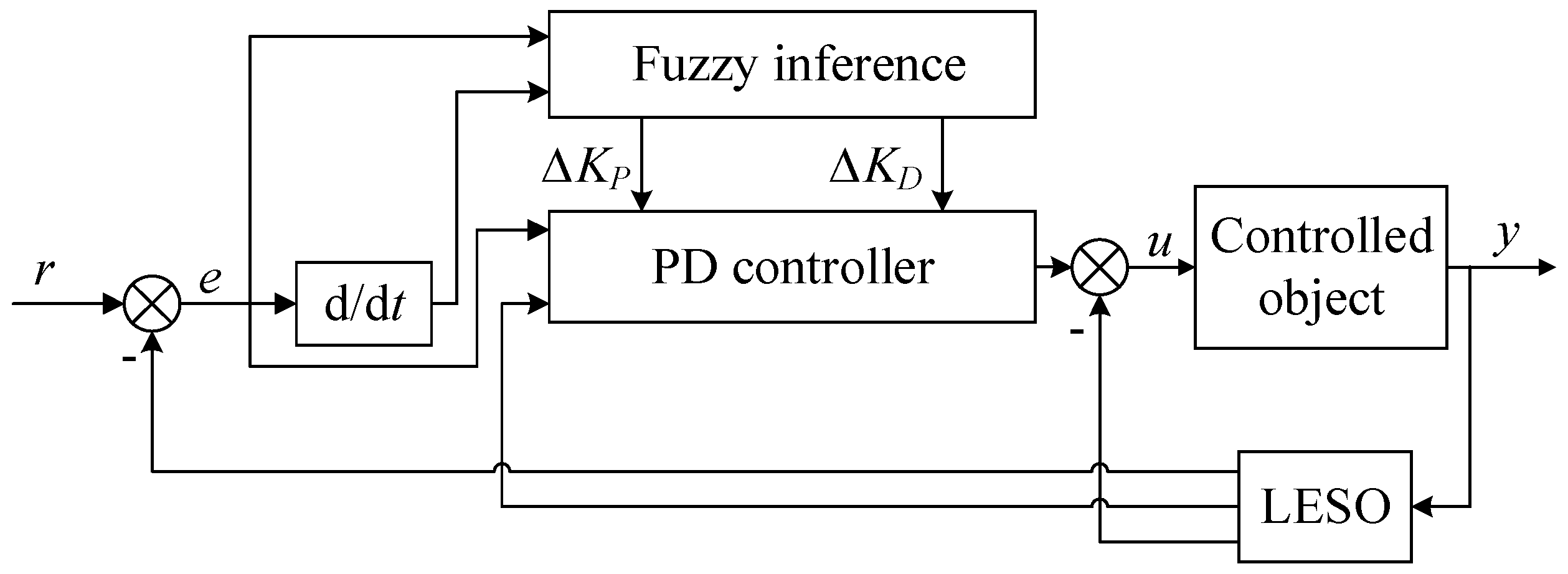
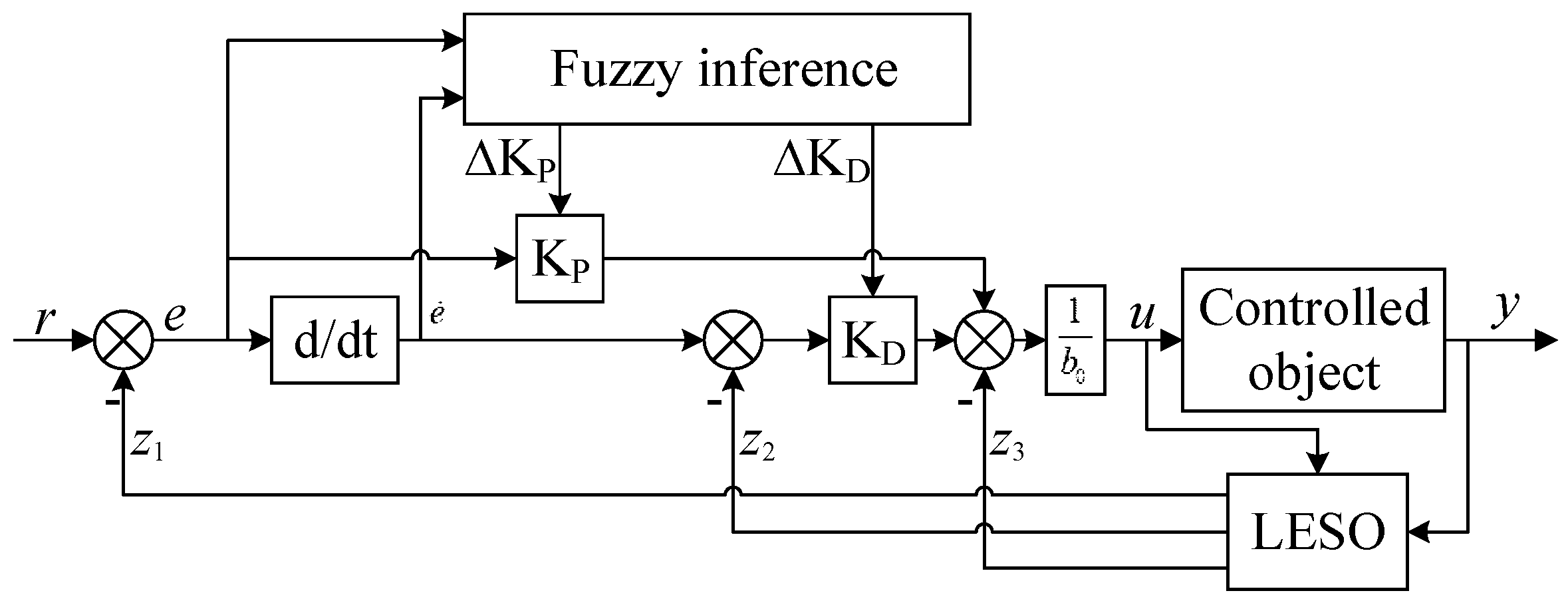
The LESO expands the disturbance which affects the output of the controlled object into a new state variable. A special feedback mechanism is used to establish an observer which can observe the extended state, that is, the extended state observer of perturbation. This LESO can observe, estimate and compensate disturbances without relying on the perturbation generating model or direct measurement. Under the disturbance compensation effect of LESO, the noise signal is effectively suppressed, and the static difference is effectively compensated. Therefore, the derivative element can be added to the controller and the integral element eliminating static error can be replaced by LESO. The introduction of LESO not only avoids problems such as slow response, easy oscillation and control quantity saturation caused by the integration link, but also inhibits the oscillation and overshoot in the transient process. The controller structure is shown in Figure 7.
Without relying on the precise mathematical model of the system, LESO is able to estimate the various order state variables and generalized disturbance real time values of the controlled object and make compensation to simplify the controlled object. Express n-order system with differential equation, as follows:
y ( n ) = f ( t , y , y ˙ , , y ( n 1 ) , u , u ˙ , , u ( n 1 ) , w ) + b u
where u and y depict the input and output of the controlled object; w represents the unknown disturbance. The f is the generalized disturbance of the unmodeled part of the WECS, the external disturbance and the estimation error, including all the uncertain terms in the WECS. The b is the input control gain, and b can be estimated, assuming that the estimated value is b 0 .
Suppose x 1 = y , x 2 = y ˙ , , x ( n ) = y ( n 1 ) , x ( n + 1 ) = f , X = [ x 1 x 2 x ( n + 1 ) ] T , the f is differentiable. The dynamic model of LESO is [34,35,36]:
{ X ˙ = A X + B u + E f ˙ y = C X A = [ 0 0 1 0 0 1 0 0 0 0 0 1 0 0 0 0 ] ( n + 1 ) × ( n + 1 ) , B = [ 0 0 b 0 0 ] ( n + 1 ) × 1 , C = [ 1 0 0 0 ] 1 × ( n + 1 ) , E = [ 0 0 0 1 ] ( n + 1 ) × 1
The generalized disturbance term f in the WECS, namely the state variable x n + 1 , can be estimated by the extended state observer, as follows:
{ Z ˙ = A X + B u + L ( y y ^ ) y ^ = C Z
where Z is the state variable matrix of the extended state observer, and Z ˙ depicts the state variable derivative matrix. L represents the state observer gain matrix to be designed, as follows:
L = [ l 1 l 2 l n l n + 1 ] T
The observer bandwidth is introduced to set the parameter L. In the equation, l 1 ,   l 2 ,     ,   l n ,   l n + 1 are the parameter of matrix L, which can be parameterized to make the observer characteristic polynomial be:
s n + 1 + l 1 s n + + l n s + l n + 1 = ( s + ω 0 ) n + 1
When the system is asymptotically stable, the observer’s state variable z i ( i = 1 , 2 , 3 , , n + 1 ) will track the system state variable x 1 , that is: z 1 y , z 2 y ˙ , z 3 y ¨   , , z n + 1 f .

4. Design of a Controller for a Wind Energy Conversion System

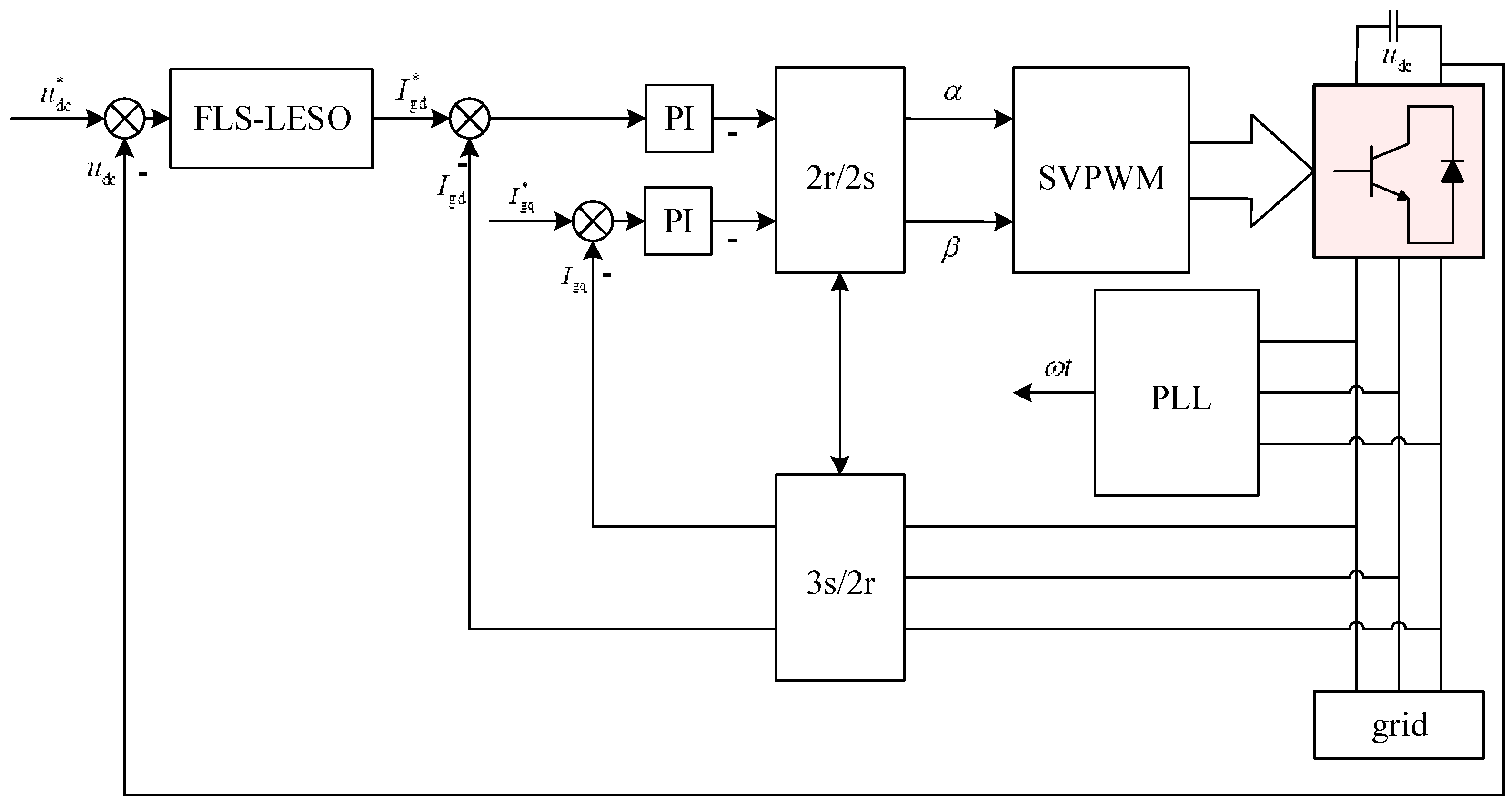
The fuzzy control algorithm is used to design the wind turbine grid connection control strategy with parameter adaptive ability, and LESO is introduced into the wind power grid connection technology to solve the problem of voltage and power instability. The control diagram of output voltage and output current of the converter is shown in Figure 8.
Under the traditional single closed-loop control strategy, feed-forward decoupling is often used to deal with the coupling term. Because this decoupling method increases the difficulty of controller design and the uncertainty of parameters, it is hindered in practical application. When inputs and outputs are in one-to-one correspondence, cross-effects (coupling) between channels are estimated by the LESO and eliminated as disturbances in each single input single output loop. In other words, the cross coupling is naturally decoupled, so the FLS-LESO has naturally decoupling characteristic. Due to the complexity and uncertainty of transient process dynamics, it is impossible for the process model to be completely accurate and reliable. Due to its natural decoupling capability, the FLS-LESO far outperforms PID and other model-based methods in controlling coupled systems, and its controller structure is shown in Figure 9.
Figure 9. FLS-LESO structure.
Energies 12 02862 g009
where z 1 is the observed value of output, z 2 is the observed value of the first derivative of output, and z 3 is the observed value of the total disturbance.
For this WECS, we can obtain partial model information of wind power system. Integrating some of the known information into LESO can reduce the bandwidth of LESO or improve the estimation accuracy of disturbance without reducing the bandwidth of LESO. The LESO integrated system information has its particularity and uniqueness.
Where T f is the equivalent time constant of sampling and filtering links, the 2T represents the equivalent time constant of current inner ring, and K c is the conversion link coefficient (0.75). The C depicts the capacitance parameter of DC bus. From the Figure 10, The open-loop transfer function without control can be obtained, as follows:
G ( s ) = K C C s ( T f s + 1 ) ( 2 T s + 1 )
Since T f and T are both small, small inertial element can be combined to simplify, as follows:
G ( s ) = K C C s [ ( T f + 2 T ) s + 1 ]
Carry out inverse Laplace transform to get the equivalent differential equation of the system. Assuming that w is unknown and b 0 is a known part of b, as follows:
y ¨ = a 1 y ˙ a 0 y + ( b b 0 ) u + w + b 0 u
with a 0 = 0 , a 1 = 1 / ( 2 T + T f ) and b 0 = K C / C ( 2 T + T f ) used as substitutions.
Suppose the total disturbance of actual unknown, as follows:
f = ( b b 0 ) u + w
where f is the sum of the unknown total disturbance.
The sum of the unknown total disturbance and the known object information is regarded as the expansion of the disturbance and denoted as f, as follows:
f = a 1 y ˙ a 0 y + f
Select the state variable: x 1 = y , x 2 = y ˙ , x 3 = f , then x = [ y y ˙ f ] T is the expansion state including disturbance, which is transformed into the continuous state space description, as follows:
[ x ˙ 1 x ˙ 2 x ˙ 3 ] X ˙ = [ 0 1 0 0 0 1 0 a 0 a 1 ] A [ x 1 x 2 x 3 ] X + [ 0 b 0 a 1 b 0 ] B u + [ 0 0 1 ] E f ˙ y = [ 1 0 0 ] C [ x 1 x 2 x 3 ] X
where A R 3 × 3 , B R 3 × 1 , C R 1 × 3 , E R 3 × 1 are LESO matrices.
Corresponding continuous LESO is, as follows:
{ Z ˙ = A X + B u + L ( y y ^ ) y ^ = C Z
where, ZX, Z is the state vector of the observer, and L represents the observer gain matrix to be designed. Since f ˙ 1 is unknown and can be estimated by correction, f ˙ 1 is omitted. Rewrite the observer equation, as follows:
{ Z ˙ = [ A L C ] Z + [ B L ] U c Y c = C Z
where U c = [ u y ] T depicts the combined input, and Y c is the output.
After parameterization, all the observer poles are configured at ω 0 , as follows:
λ ( s ) = | s I ( A L C ) | = ( s + ω 0 ) 3
where ω 0 is the observer bandwidth. The observer gain matrix is calculated, as follows:
L = [ l 1 l 2 l 3 ] = [ 3 ω 0 a 1 3 ω 0 2 3 a 1 ω 0 a 0 + a 1 2 ω 0 3 3 a 1 ω 0 2 + 3 ( a 1 2 a 0 ) + 2 a 0 a 1 a 1 3 ]
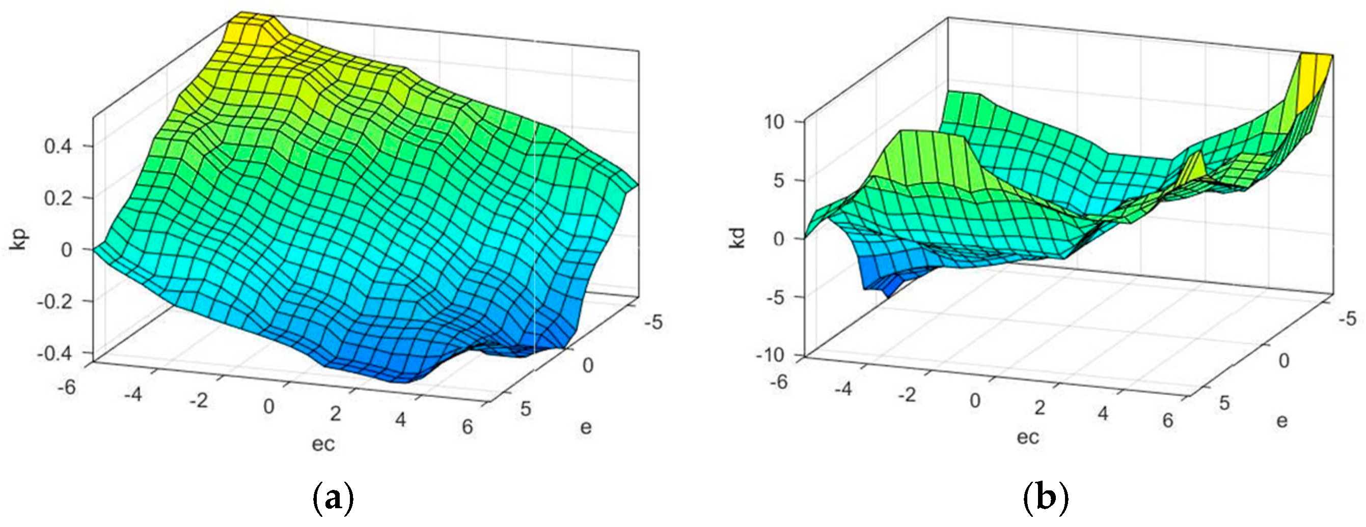
The FLS-LESO replaces the traditional control strategy to improve the output of the system in the outer ring of the converter. The two inputs of the fuzzy PD controller are the error ( e ( t ) = u d c * u dc ( t ) ) of the DC bus voltage, and the error derivative ( Δ e ( t ) = e ( t + 1 ) e ( t ) ) of the DC bus voltage. Δ K P and Δ K D are the output language variable, and the range of variation is defined as the basic domain on fuzzy set. The basic domain of the two inputs e and e ˙ is [−6,6], and their fuzzy sets are {NB, NM, NS, ZO, PS, PM, PB}. The basic domain of the two outputs Δ K P and Δ K D is [−0.6,0.6] and [−12,12], respectively. Their fuzzy sets are {NB, NM, NS, ZO, PS, PM, PB}. The elements in the subset represent negative big, negative middle, negative small, zero, positive small, positive middle and positive big. The quantity of continuous change in the basic domain is discretized and fuzzy processing is carried out. Set the range of variation of DC bus voltage deviation e and deviation derivative e ˙ as [−6,6]. If not within this range, a continuous quantity with a value between [a,b] can be converted to [−6,6] by linear transformation.
y = 12 b a ( x a + b 2 )
In this paper, the control rules and membership functions are determined based on the trial and error and the designer experience. the membership functions are composed of three memberships functions (two-inputs and one-output) and each membership function has seven triangular memberships. For this case, controller rules are used as shown in Table 1.
From the Equation (19), the general expression of the state space of the system can be obtained, as follows:
{ x ¨ = a 1 x ˙ a 0 x + u y = x
PD control, as follows:
{ e = r 0 x u = K P e + K D e ˙
From Equations (28) and (29), the closed-loop system is obtained:
{ e ˙ 0 = e , e 0 ( 0 ) = 0 e ˙ = ( K P + a 0 ) e ( K D + a 1 ) e ˙ , e ( 0 ) = r 0
After Laplace transform, the following relations are obtained according to Routh criterion:
{ K P + a 0 > 0 K D + a 1 > 0
From Equation (31), the range of PD parameters can be obtained, and the upper and lower limits of the fuzzy PD controller can be designed to ensure the stability of the system operation. The output surface of fuzzy controller is shown in Figure 11.

5. Simulation Study

The simulations in this study were realized in Matlab/Simulink to verify the effectiveness and analysis of the presented method. The sampling time of the presented Simulink system was modeled at 1 × 10⁻⁶ s. The parameters of the PMSG and power converter systems are given in Table A1, respectively. An open source FLCWR toolbox in Matlab/Simulink was used in this study. The rules of the FLS-LESO system were designed to maximize the wind energy conversion system. The fuzzy rules were adjusted to generate the optimized gains for the power performance of the wind system based on the PMSG. An FLS-LESO control system was implemented for the analysis of four different cases of grid-side and machine-side fault. The different types of symmetrical and asymmetrical faults were implemented separately at the proper time on the grid-side of the PMSG. The simulated fault conditions were as follows:
(i)
The 50% symmetrical fault was implemented at t = 2.0 s and was cleared at t = 2.5 s;
(ii)
The asymmetrical fault was implemented at t = 2.0 s and was cleared at t = 2.5 s;
(iii)
The 30% increase in wind turbine power at t = 2.0 s and was cleared at t = 2.5 s;
(iv)
The 30% decrease in wind turbine power at t = 2.0 s and was cleared at t = 2.5 s.
The generator with the proposed control method was connected to the grid during all grid fault types. The simulation results illustrate that the FLS-LESO gives an appropriate performance for the power generation of the wind system using a PMSG for different scenarios. The rated value of the DC link was 1070 V, the rated value of voltage was 1 p.u., and the rated value of the current was 1 p.u. in the study.
Scenario 1
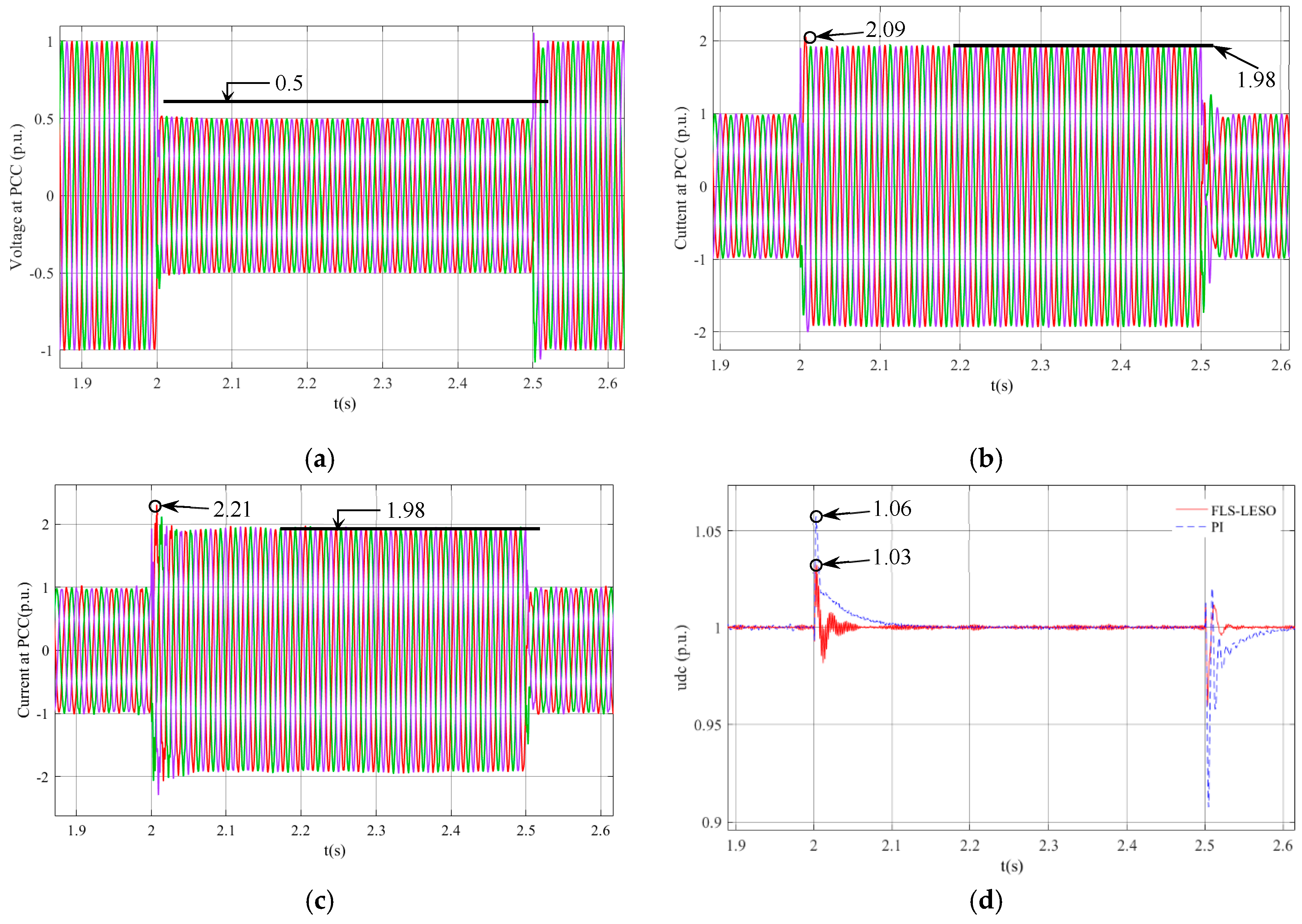
The 50% symmetrical fault was implemented at t = 2.0 s, and then it was cleared at t = 2.5 s, as shown in Figure 12a. The 50% symmetrical fault was the severer fault type used. Therefore, the control of this fault type is vital. The FLS-LESO and PI controller were separately implemented in the WECS. The parameters of the WECS that were measured were the DC link ( u d c ), grid voltage ( U a b c ), and grid current ( I a b c ). The maximum value of the current at the point of common coupling (PCC) with the PI controller was 2.09 p.u., and it fluctuates around 1.98 p.u., as shown in Figure 12b. However, the maximum value of the current at the PCC with the FLS-LESO was 2.21 p.u., and it also fluctuates around 1.98 p.u., as shown in Figure 12c. The DC link voltage of the system is given in Figure 12d. The DC link peak voltage value using a PI controller was 1.06 p.u. during the grid fault, while the DC link peak voltage value with the FLS-LESO was 1.03 p.u. The oscillation of the DC link voltage value with the PI controller was higher than the proposed control system even after the grid fault time. The oscillation of the DC link voltage value with the PI controller was higher than the proposed control system even after the grid fault time.
Scenario 2
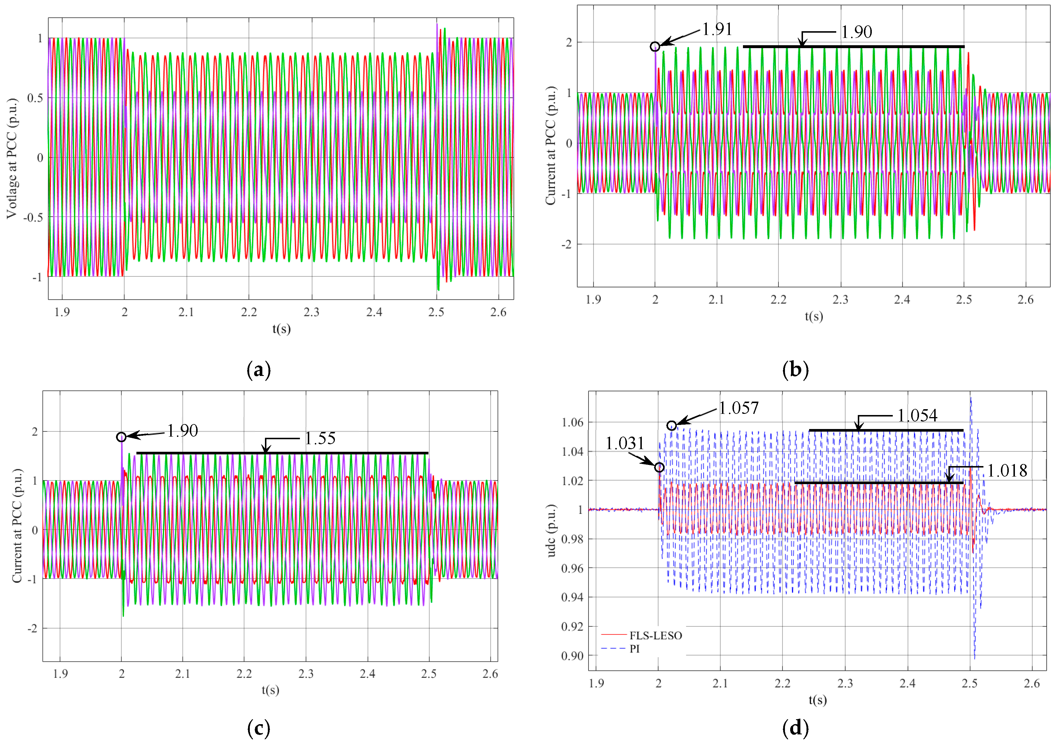
The asymmetrical fault was implemented at t = 2.0 s, and then it was cleared at t = 2.5 s, as shown in Figure 13a. The asymmetrical fault was also severer fault type. The FLS-LESO and traditional PI controller were separately implemented in the system during the asymmetrical fault, as shown in Figure 13a. The DC link, grid voltage, and grid current of the system with the FLS-LESO are given in Figure 13b–d, respectively. The current at the PCC with the traditional PI controller system increased to 1.91 p.u., and it fluctuates around 1.90 p.u., as shown in Figure 13b. However, the maximum value of the current at the PCC with the FLS-LESO was 1.90 p.u., and it fluctuates around 1.55 p.u., as shown in Figure 13c. The overshoot value of the DC link with the traditional PI controller system was 1.057 p.u., as shown in Figure 13d. The overshoot value of the DC link voltage with the FLS-LESO was 1.031 p.u., and the overshoot in the DC link voltage was greatly reduced by the FLS-LESO. The ripples in the DC link voltage value with the traditional PI controller system were higher than the proposed control system even after the grid fault time.
Scenario 3
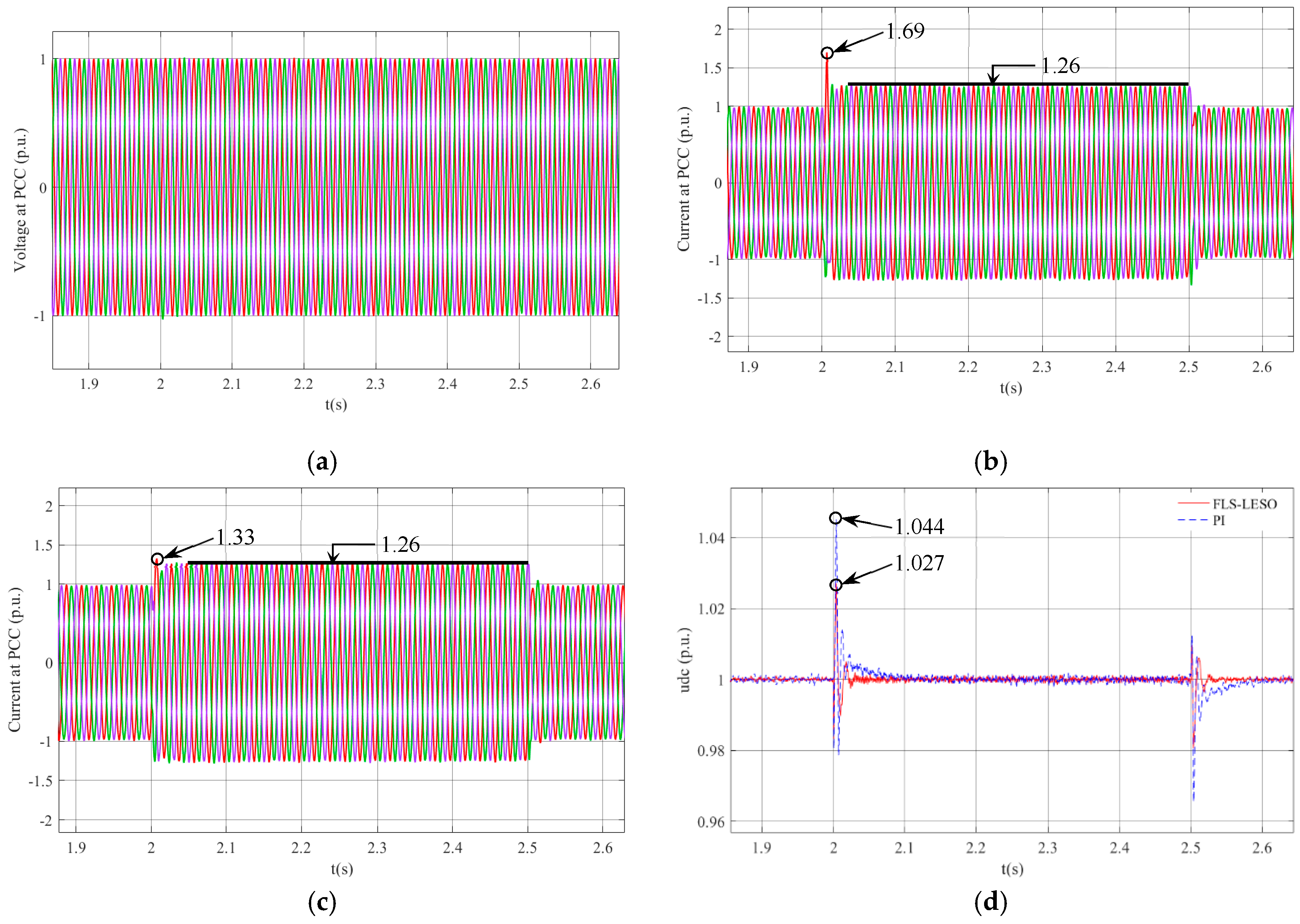
The 30% increase in wind turbine power at t = 2.0 s and was cleared at t = 2.5 s, as shown in Figure 14a. The wind turbine power fluctuation was lighter than the other fault types. However, the power fluctuation is the most common type of turbine side disturbance. Therefore, the control of this fault type is vital. The parameters of the WECS that were measured were the DC link, grid voltage, and grid current. The maximum value of the current at the point of common coupling (PCC) with the PI controller was 1.69 p.u., and it fluctuates around 1.26 p.u., as shown in Figure 14b. However, the maximum value of the current at the PCC with the FLS-LESO was 1.33 p.u., and it also fluctuates around 1.26 p.u., as shown in Figure 14c. The DC link voltage of the system is given in Figure 14d. The DC link peak voltage value using a PI controller was 1.044 p.u., and the DC link peak voltage value with the FLS-LESO was 1.027 p.u. The overshoot value of the current at PCC and the DC link were greatly reduced by the FLS-LESO.
Scenario 4
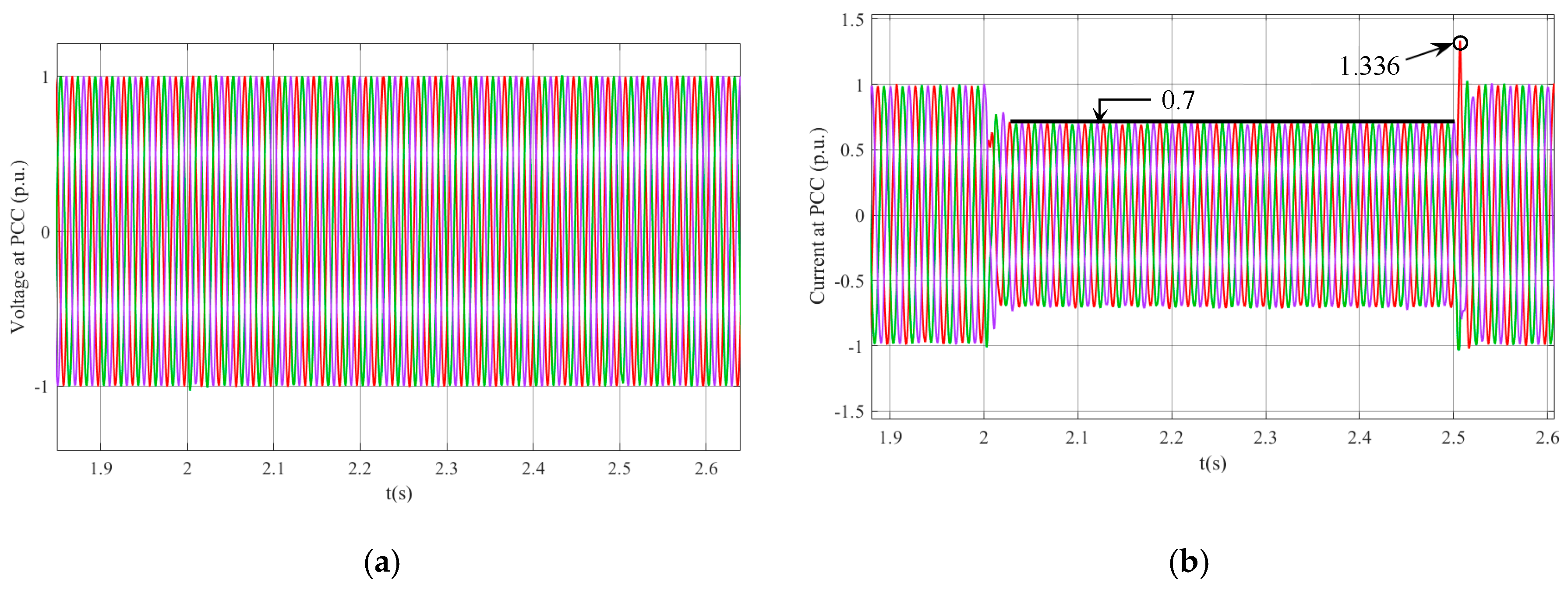
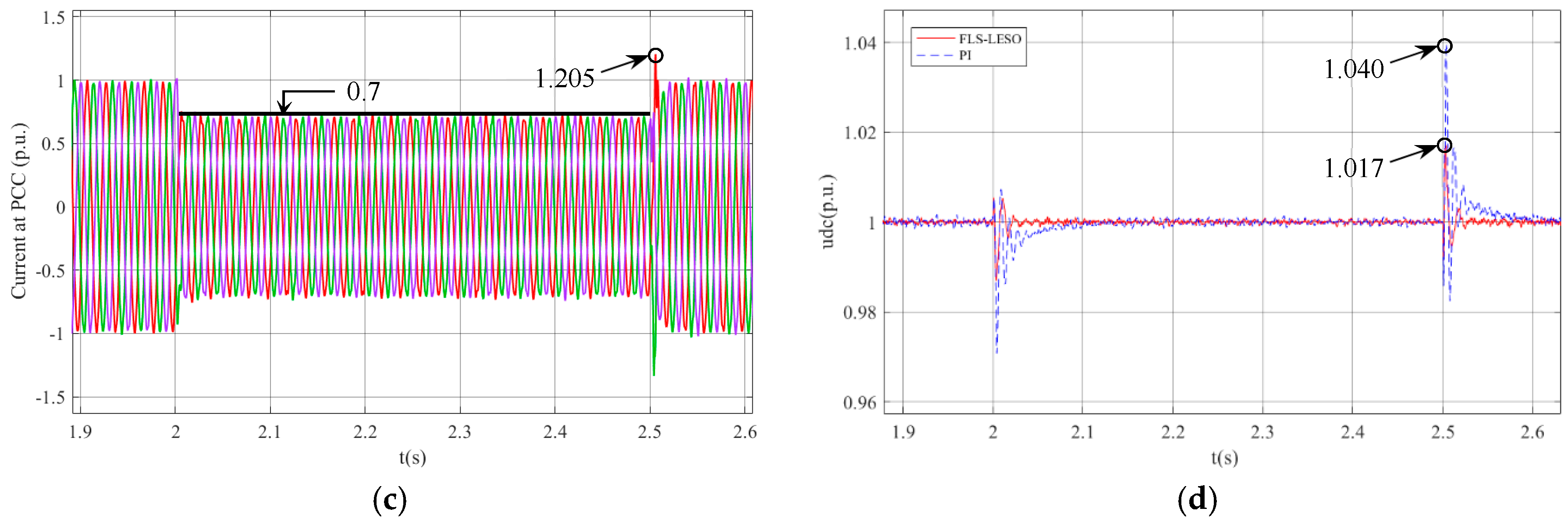
The 30% decrease in wind turbine power at t = 2.0 s and was cleared at t = 2.5 s. The grid voltage remains constant during this period, as shown in Figure 15a. The parameters of the WECS that were measured were the DC link, grid voltage, and grid current. The current at the PCC with the traditional PI controller system increased to 1.336 p.u., and it fluctuates around 0.7 p.u., as shown in Figure 15b. However, the maximum value of the current at the PCC with the FLS-LESO was 1.205 p.u., and it also fluctuates around 0.7 p.u., as shown in Figure 15c. The DC link peak voltage value using a PI controller was 1.040 p.u. during the grid fault, while the DC link peak voltage value with the FLS-LESO was 1.017 p.u., as shown in Figure 15d The overshoot value of the current at PCC and the DC link were greatly reduced by the FLS-LESO.
The parameters with the proposed control system settled to the rated value within comparatively less time than with the traditional PI controller. The proposed control system reduced the ripples of all the parameters in the system due to the appropriate selection of FLS-LESO parameters.

6. Conclusions

The FRT capability of wind turbines is a vital issue for the electrical energy generated from wind energy and contributes to reliable grid integration. This paper proposes a new control approach using the FLS-LESO method that is implemented in the WECS based on a PMSG to improve the transient stability during grid faults and wind turbine power fluctuation. The main contributions of this work are:
(i)
The FLS-LESO was designed to enhance the fault ride-through performance of the WECS in order to obtain effective results during grid faults;
(ii)
The proposed control system was applied to control the GSC of the PMSG;
(iii)
It was observed by measurements that the proposed control system protects the power of electronic devices from the harmful effect of overvoltage during grid faults;
(iv)
The simulation results have confirmed that the proposed control system can effectively reduce the ripples of the parameters in the system.
The parameters of the system that were observed were the DC link, grid voltage, and grid current. The DC link of the system with the FLS-LESO had near nominal values. All the parameters of the system with the FLS-LESO closely tracked the rated values during and after the grid faults. All the parameters with the proposed control system settled to the rated value within comparatively less time than the traditional PI system. All the simulation results proved that the presented FLS-LESO scheme has the capability to improve the FRT capability of the WECS and performs better than the traditional PI system in all aspects.
In the future, the other rule evaluation method should be applied to the system. In addition, different fuzzy logic control systems, such as the interval fuzzy logic control with LESO, can be adapted to improve the FRT performance of WECSs, and the results can be compared with the results in this paper.
Author Contributions

All authors participated at the paper through a wide and balanced cooperation. They all worked at the mathematical model, the simulation set-up, the experiments and writing the manuscript. All authors have read and approved the manuscript.

Funding

This work was funded by National Natural Science foundation of China (NO. 51877152) and Natural Science Foundation of Tianjin of China (NO. 18JCZDJC97300).

Acknowledgments

The authors are thankful to National Natural Science foundation of China (NO. 51877152), Natural Science Foundation of Tianjin of China (NO. 18JCZDJC97300) and Tianjin University of Technology for their support.

Conflicts of Interest

The authors declare no conflict of interest.

Nomenclature

PgRated generator power
ω e electric angular of the PMSG
ψ f flux linkage in the permanent magnets
isd, isqgenerator dq frame currents
Ld, Lqstator inductances in the dq frame
Igq, Igdgrid dq frame currents
LgFilter grid-side inductance
ω electric angular of the grid
Abbreviations
AcronymDefinition
FLS-LESOFuzzy logic system with the linear extended state observer
WECSWind energy conversion system
LESOLinear extended state observer
PMSGPermanent magnet synchronous generator
BCBraking chopper
FRTFault ride-through
GSCGrid-side converter
MSCMachine-side converter
GCRGrid connection requirement
STATCOMStatic synchronous compensator
SFCLSuperconducting fault current limiter
MPPMaximum power point tracking
DFIGDoubly fed induction generator
WTWind turbine

Appendix A

Table A1. Main parameters of the wind energy conversion system.
ParameterSymbolValueUnit
Base powerPb1.5MW
Base voltageVb690V
Base frequencyfb50Hz
Rated generator powerPg1pu
Pole pairs of PMSG np12
Stator phase resistanceRs0.0009Ω
Flux linkageϕ1.49V.s
Stator inductanceLd, Lq0.573, 0.874mH
Machine-side filter resistanceRls0.0002Ω
DC capacitanceC0.024F
DC link voltage u d c 1070V
Grid-side filter resistanceRg0.0009Ω
Grid-side filter inductanceLg0.12mH
Grid-side filter capacitanceCg0.0015F

References

  1. Huenteler, J.; Niebuhr, C.; Schmidt, T.S. The effect of local and global learning on the cost of renewable energy in developing countries. J. Clean. Prod. 2016, 128, 6–21. [Google Scholar] [CrossRef]
  2. Singaravel, M.M.R.; Daniel, S.A. MPPT with Single DC-DC Converter and Inverter for Grid Connected Hybrid Wind-Driven PMSG-PV System. IEEE Trans. Ind. Electron 2015, 62, 4849–4857. [Google Scholar] [CrossRef]
  3. Zhang, Z.; Wang, F.; Wang, J.; Rodríguez, J.; Kennel, R. Nonlinear Direct Control for Three-Level NPC Back-to-Back Converter PMSG Wind Turbine Systems: Experimental Assessment with FPGA. IEEE Trans. Ind. Inform. 2017, 13, 1172–1183. [Google Scholar] [CrossRef]
  4. Yuan, Y.H.; Wu, F. Short-Circuit Current Analysis for DFIG Wind Farm Considering the Action of a Crowbar. Energies 2018, 11, 425. [Google Scholar] [CrossRef]
  5. Abdelrahem, M.; Hackl, M.C.; Kennel, R. Simplified model predictive current control without mechanical sensors for variable-speed wind energy conversion systems. Electr. Eng. 2017, 99, 367–377. [Google Scholar] [CrossRef]
  6. Gencer, A. Analysis and control of low-voltage ride-through capability improvement for PMSG based on an NPC converter using an interval type-2 fuzzy logic system. Elektron. Elektrotech. 2019, 25, 63–70. [Google Scholar] [CrossRef]
  7. Zhu, Y.; Zhu, C.; Song, C.; Li, Y.; Chen, X.; Yong, B. Improvement of reliability and wind power generation based on wind turbine real-time condition assessment. Int. J. Electr. Power Energy Syst. 2019, 113, 344–354. [Google Scholar] [CrossRef]
  8. Nian, H.; Xu, Y.; Chen, L.; Li, G. Frequency coupling characteristic modeling of grid-connected inverter and system stability analysis. Proc. CSEE 2019, 39, 1421–1431. [Google Scholar]
  9. Zeng, X.; Yao, J.; Chen, Z.; Hu, W.; Chen, Z.; Zhou, T. Co-Ordinated Control Strategy for Hybrid Wind Farms With PMSG and FSIG Under Unbalanced Grid Voltage Condition. IEEE Trans. Sustain. Energy 2016, 7, 1100–1110. [Google Scholar] [CrossRef] [Green Version]
  10. Ghatikar, G.; Mashayekh, S.; Stadler, M.; Yin, R.; Liu, Z. Distributed Energy Systems Integration and Demand Optimization for Autonomous Operations and Electric Grid Transactions. Appl. Energy 2016, 167, 432–448. [Google Scholar] [CrossRef]
  11. Alepuz, S.; Calle, A.; Busquets, M.S.; Kouro, S.; Wu, B. Use of Stored Energy in PMSG Rotor Inertia for Low-Voltage Ride-Through in Back-to-Back NPC Converter-Based Wind Power Systems. IEEE Trans. Ind. Electron 2013, 60, 1787–1796. [Google Scholar] [CrossRef]
  12. Hossain, M.E. A non-linear controller based new bridge type fault current limiter for transient stability enhancement of DFIG based Wind Farm. Electr. Power Syst. Res. 2017, 152, 466–484. [Google Scholar] [CrossRef]
  13. Pulido, A.B.; Romero, J.; Enriquez, H.C. Robust Active Disturbance Rejection Control for LVRT capability enhancement of DFIG-based wind turbines. Control Eng. Pract. 2018, 77, 174–189. [Google Scholar] [CrossRef]
  14. Jerin, A.R.A.; Kaliannan, P.; Subramaniam, U. Improved fault ride through capability of DFIG based wind turbines using synchronous reference frame control based dynamic voltage restorer. ISA Trans. 2017, 70, 465–474. [Google Scholar] [CrossRef] [PubMed]
  15. Nasiri, M.; Mohammadi, R. Peak Current Limitation for Grid-side Inverter by Limited Active Power in PMSG-Based Wind Turbines during Different Grid Faults. IEEE Trans. Sustain. Energy 2017, 8, 3–12. [Google Scholar] [CrossRef]
  16. Gencer, A. Analysis and Control of Fault Ride Through Capability Improvement PMSG Based on WECS Using Active Crowbar System During Different Fault Conditions. Elektron. Elektrotech. 2018, 24, 64–69. [Google Scholar] [CrossRef]
  17. Yehia, D.M.; Mansour, D.A.; Yuan, W. Fault Ride-Through Enhancement of PMSG Wind Turbines with DC icrogrids Using Resistive-Type SFCL. IEEE Trans. Appl. Supercond. 2018, 28, 1–5. [Google Scholar]
  18. Geng, H.; Liu, L.; Li, R. Synchronization and Reactive Current Support of PMSG-Based Wind Farm during Severe Grid Fault. IEEE Trans. Sustain. Energy 2018, 9, 1596–1604. [Google Scholar] [CrossRef]
  19. Conroy, J.F. Watson Low-voltage ride-through of a full converter wind turbine with permanent magnet generator. IET Renew. Power Gener. 2007, 1, 182–189. [Google Scholar] [CrossRef]
  20. Yang, S.; Zhou, T.; Sun, D.; Xie, Z.; Zhang, X. A SCR crowbar commutated with power converter for DFIG-based wind turbines. Int. J. Electr. Power Energy Syst. 2016, 1, 87–103. [Google Scholar] [CrossRef]
  21. Nasiri, M.; Milimonfared, J.; Fathi, S.H. A review of low-voltage ride-through enhancement methods for permanent magnet synchronous generator based wind turbine. Renew. Sustain. Energy Rev. 2015, 4, 399–415. [Google Scholar] [CrossRef]
  22. Han, X.; Ma, Y. Finite-time extended dissipative control for fuzzy systems with nonlinear perturbations via sampled-data and quantized controller. ISA Trans. 2019, 89, 31–44. [Google Scholar] [CrossRef] [PubMed]
  23. Mohammadikia, R.; Aliasghary, M. A Fractional Order Fuzzy Pid for Load Frequency Control of Four-area Interconnected Power System Using Biogeography-based Optimization. Int. Trans. Electr. Energy Syst. 2019, 29. [Google Scholar] [CrossRef]
  24. Gaidhane, P.J.; Nigam, M.J.; Kumar, A.; Pradhan, P.M. Design of interval type-2 fuzzy precompensated PID controller applied to two-DOF robotic manipulator with variable payload. ISA Trans. 2019, 89, 169–185. [Google Scholar] [CrossRef] [PubMed]
  25. Zadeh, L.A. The concept of a linguistic variable and its application to approximate reasoning. Inf. Sci 1975, 8, 43–80. [Google Scholar] [CrossRef]
  26. Shao, X.; Wang, L.; Li, J.; Liu, J. High-order ESO based output feedback dynamic surface control for quadrotors under position constraints and uncertainties. Aerosp. Sci. Technol. 2019, 89, 288–298. [Google Scholar] [CrossRef]
  27. Li, Y.; Xu, Z.; Wong, K.P. Advanced Control Strategies of PMSG-Based Wind Turbines for System Inertia Support. IEEE Trans. Power Syst. 2017, 32, 3027–3037. [Google Scholar] [CrossRef]
  28. Priyadarshi, N.; Ramachandaramurthy, V.; Padmanaban, S.; Azam, F. An ant colony optimized MPPT for standalone hybrid PV-wind power system with single Cuk converter. Energies 2019, 12, 167. [Google Scholar] [CrossRef]
  29. Lee, S.W.; Chun, K.H. Adaptive Sliding Mode Control for PMSG Wind Turbine Systems. Energies 2019, 12, 595. [Google Scholar] [CrossRef]
  30. Lind, P.G.; VeraTudela, L.; Wächter, M.; Kühn, M.; Peinke, J. Normal behaviour models for wind turbine vibrations: Comparison of neural networks and a stochastic approach. Energies 2017, 10, 1944. [Google Scholar] [CrossRef]
  31. Li, S.; Haskew, T.A.; Xu, L. Conventional and novel control designs for direct driven PMSG wind turbines. Electr. Power Syst. Res. 2010, 80, 328–338. [Google Scholar] [CrossRef]
  32. Yanghong, T.; Haixia, Z.; Ye, Z. A Simple-to-Implement Fault Diagnosis Method for Open Switch Fault in Wind System PMSG Drives without Threshold Setting. Energies 2018, 11, 2571. [Google Scholar] [CrossRef]
  33. AbouOmar, M.S.; Zhang, H.J.; Su, Y.X. Fractional Order Fuzzy PID Control of Automotive PEM Fuel Cell Air Feed System Using Neural Network Optimization Algorithm. Energies 2019, 12, 1435. [Google Scholar] [CrossRef]
  34. Gao, Z. Active disturbance rejection control: A paradigm shift in feedback control system design. In Proceedings of the American Control Conference, Minneapolis, MN, USA, 14–16 June 2006; pp. 2399–2405. [Google Scholar]
  35. Herbst, G. A simulative study on Active Disturbance Rejection Control (ADRC) as a control tool for practitioners. Electronics 2013, 2, 246–279. [Google Scholar] [CrossRef]
  36. He, T.; Wu, Z.; Shi, R.; Li, D.; Sun, L.; Wang, L.; Zheng, S. Maximum sensitivity-constrained data-driven active disturbance rejection control with application to airflow control in power plant. Energies 2019, 12, 231. [Google Scholar] [CrossRef]
Figure 1. Schematic diagram of the direct-drive permanent-magnet wind generator.
Energies 12 02862 g001
Figure 2. Topology and control structure of wind energy conversion system.
Energies 12 02862 g002
Figure 3. Schematic diagram of energy flow.
Energies 12 02862 g003
Figure 4. Fuzzy controller structure.
Energies 12 02862 g004
Figure 5. (ac). fuzzy controller with different dimensions.
Energies 12 02862 g005
Figure 6. Fuzzy controller with different dimensions.
Energies 12 02862 g006
Figure 7. Fuzzy logic system with linear extended state observer.
Energies 12 02862 g007
Figure 8. Control system structure.
Energies 12 02862 g008
Figure 10. Traditional PI control block diagram.
Energies 12 02862 g010
Figure 11. Output surface: (a) KP surface and (b) KD surface.
Energies 12 02862 g011
Figure 12. (ad). Dynamic response of a 1.5 MW permanent magnet synchronous generator (PMSG) with the traditional PI controller and fuzzy logic system with linear extended state observer (FLS-LESO) during a 50% symmetrical fault; (a) Voltage at PCC; (b) Current at PCC with the PI controller; (c) Current at PCC with the FLS-LESO; (d) DC link voltage.
Energies 12 02862 g012
Figure 13. (ad). Dynamic response of a 1.5 MW permanent magnet synchronous generator (PMSG) with the traditional PI controller and fuzzy logic system with linear extended state observer (FLS-LESO) during an unsymmetrical fault; (a) Voltage at PCC; (b) Current at PCC with the PI controller; (c) Current at PCC with the FLS-LESO; (d) DC link voltage.
Energies 12 02862 g013
Figure 14. (ad). Dynamic response of a 1.5 MW permanent magnet synchronous generator (PMSG) with the traditional PI controller and fuzzy logic system with linear extended state observer (FLS-LESO) during the 30% increase in wind turbine power; (a) Voltage at PCC; (b) Current at PCC with the PI controller; (c) Current at PCC with the FLS-LESO; (d) DC link voltage.
Energies 12 02862 g014
Figure 15. (ad). Dynamic response of a 1.5 MW permanent magnet synchronous generator (PMSG) with the traditional PI controller and fuzzy logic system with linear extended state observer (FLS-LESO) during the 30% decrease in wind turbine power; (a) Voltage at PCC; (b) Current at PCC with the PI controller; (c) Current at PCC with the FLS-LESO; (d) DC link voltage.
Energies 12 02862 g015aEnergies 12 02862 g015b
Table 1. Fuzzy rules.
Δ K P / Δ K D e
NBNMNSZOPSPMPB
e ˙ NBPB/PSPB/NSPM/NBPM/NBPS/NMZO/PSZO/PS
NMPB/PSPB/NSPM/NBPS/NMPS/NSZO/ZONS/PB
NSPM/ZOPM/NSPM/NMPS/NSZO/NSNS/ZONS/PB
ZOPM/ZOPM/NSPS/NSZO/NSNS/NSNM/ZONM/PB
PSPS/ZOPS/ZOZO/ZONS/ZONS/ZONM/ZONM/PS
PMPS/PBZO/NSNS/PSNM/PSNM/PSNM/PBNB/PS
PBZO/PBZO/PMNM/PMNS/PSNM/PSNM/PBNS/PB