Investigations of AC Microgrid Energy Management Systems Using Distributed Energy Resources and Plug-in Electric Vehicles

 ,
, 
 ,
,  ,
,  and
and 
Abstract
1. Introduction
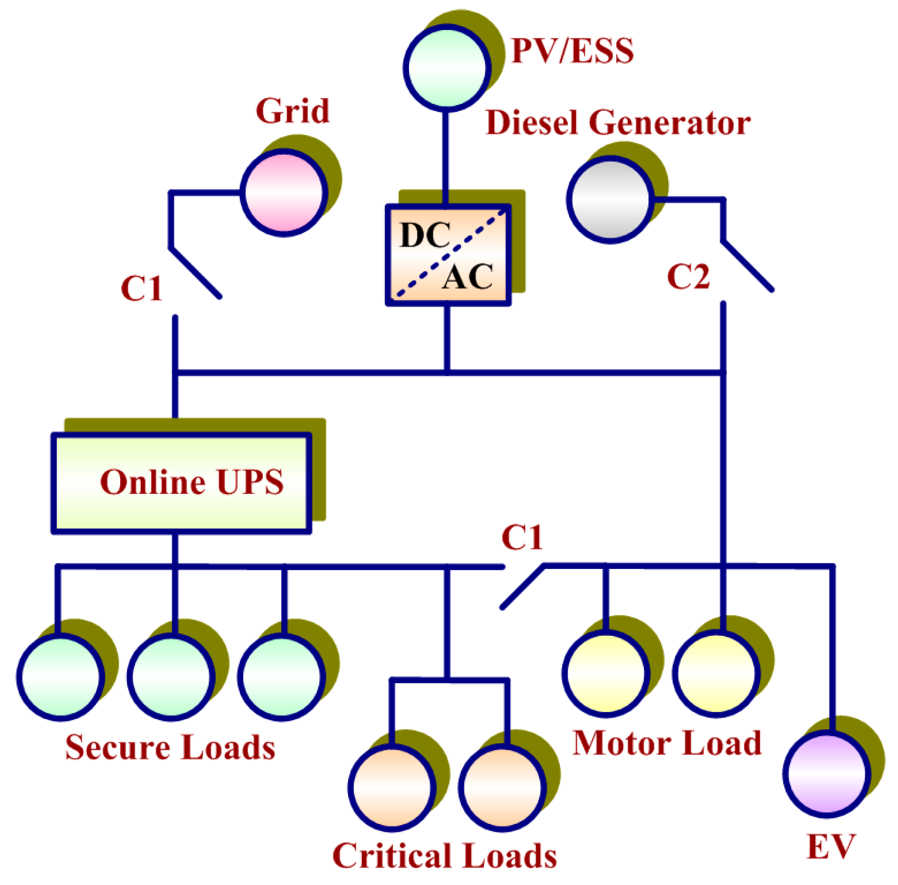
2. System Configuration
2.1. Grid
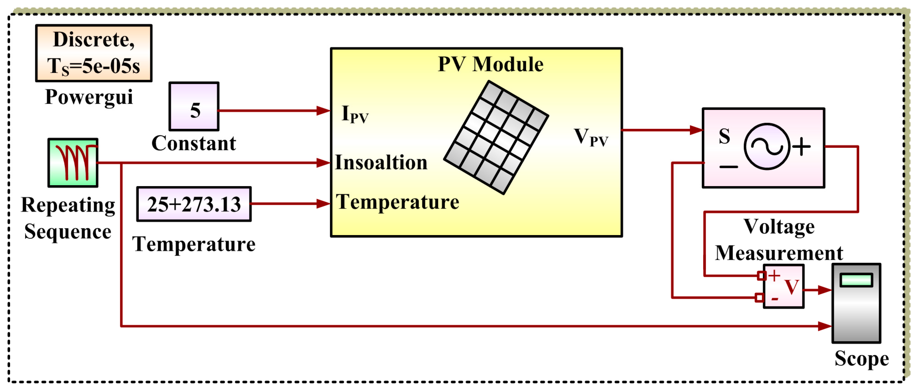
2.2. PV System
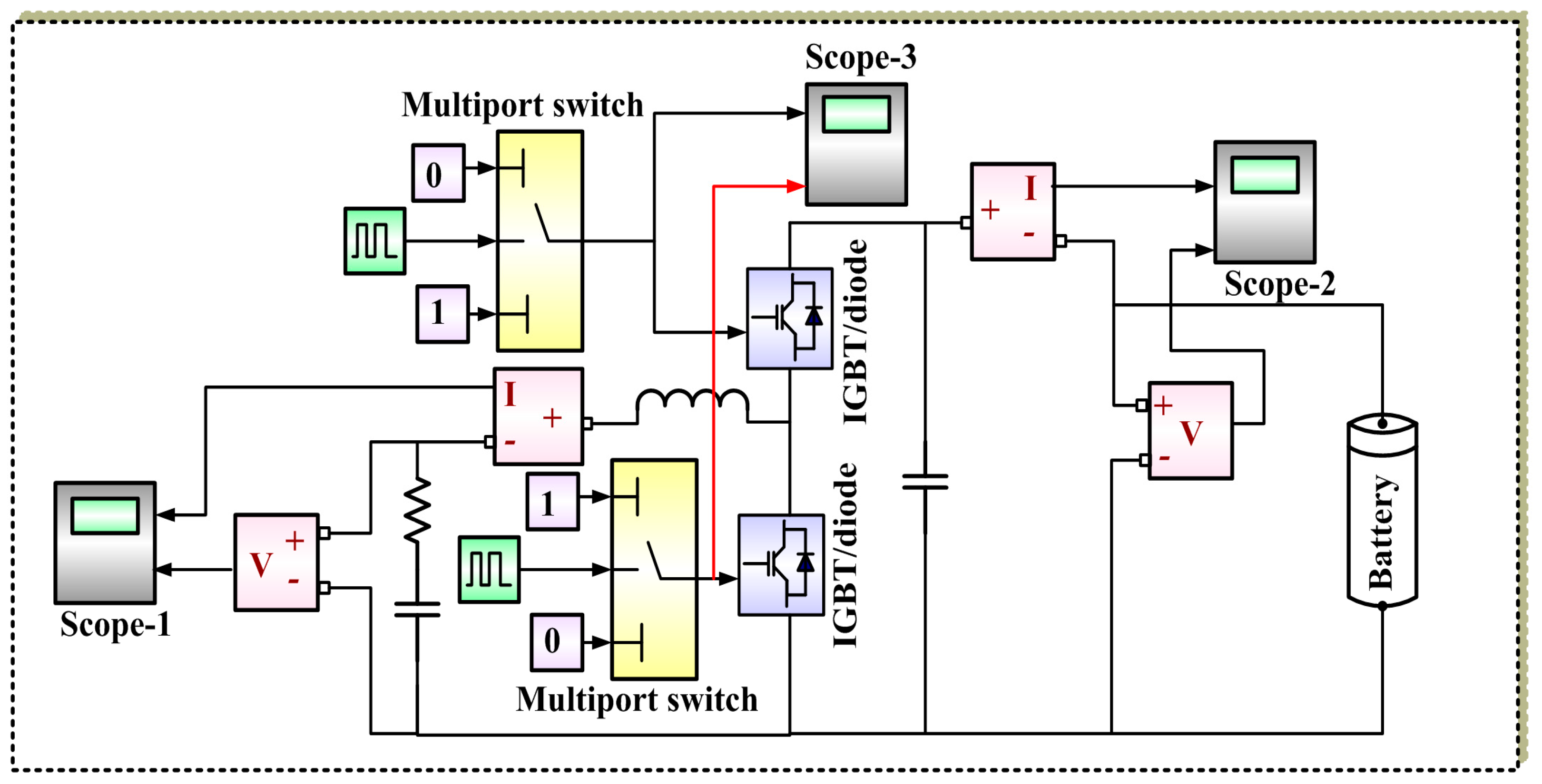
2.3. Energy Storage System
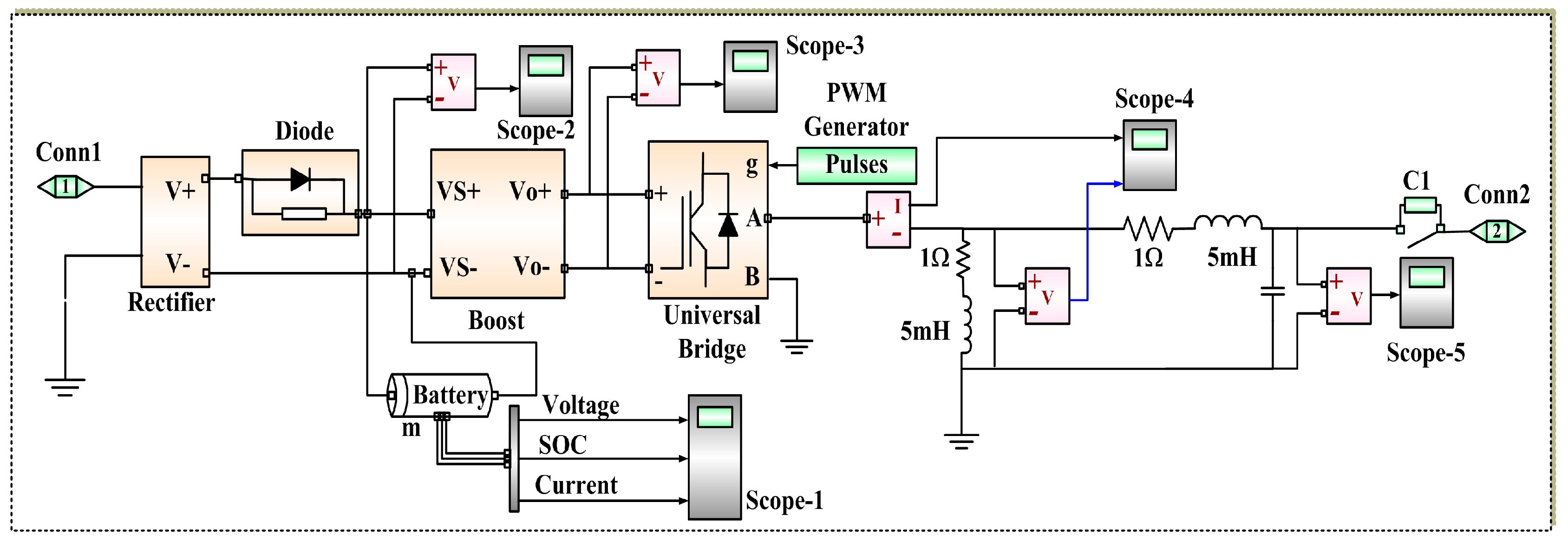
2.4. Online UPS
2.5. Loads
3. Principle States: Simulation Results
3.1. Mode I
3.2. Mode II
3.3. Mode III
3.4. Mode IV
3.5. Mode V
3.6. Mode VI
3.7. Mode VII
3.8. Mode VIII
4. Sub-States—Simulation Results
4.1. Mode I
4.2. Mode II
4.3. Mode III
4.4. Mode IV
4.5. Mode V
4.6. Mode VI
5. Conclusions
Author Contributions
Funding
Acknowledgments
Conflicts of Interest
References
- Vavilapalli, S.; Padmanaban, S.; Subramaniam, U.; Mihet-Popa, L. Power Balancing Control for Grid Energy Storage System in Photovoltaic Applications—Real Time Digital Simulation Implementation. Energies 2017, 10, 928. [Google Scholar] [CrossRef]
- Kanchev, H.; Lu, D.; Colas, F.; Lazarov, V.; Francois, B. Energy Management and Operational Planning of a Microgrid with a PV-Based Active Generator for Smart Grid Applications. IEEE Trans. Ind. Electron. 2011, 58, 4583–4592. [Google Scholar] [CrossRef]
- Ganesan, S.; Padmanaban, S.; Varadarajan, R.; Subramaniam, U.; Mihet-Popa, L. Study and Analysis of an Intelligent Microgrid Energy Management Solution with Distributed Energy Sources. Energies 2017, 10, 1419. [Google Scholar] [CrossRef]
- Chen, C.; Duan, S.; Cai, T.; Liu, B.; Hu, G. Smart energy management system for optimal microgrid economic operation. IET Renew. Power Gener. 2011, 5, 258–267. [Google Scholar] [CrossRef]
- Bhaskar, M.S.; Meraj, M.; Iqbal, A.; Padmanaban, S.; Maroti, P.K.; Alammari, R. High Gain Transformer-Less Double-Duty-Triple-Mode DC/DC Converter for DC Microgrid. IEEE Access 2019, 7, 36353–36370. [Google Scholar] [CrossRef]
- Ganesan, S.; Ramesh, V.; Umashankar, S.; Sanjeevikumar, P. Fuzzy-Based Microgrid Energy Management System Using Interleaved Boost Converter and Three-Level NPC Inverter with Improved Grid Voltage Quality. In Advances in Smart Grid and Renewable Energy; Lecture Notes in Electrical Engineering Book Series; Springer: Singapore, 2018; Volume 435, pp. 325–337. [Google Scholar]
- Gaurav, S.; Birla, C.; Lamba, A.; Umashankar, S.; Ganesan, S. Energy Management of PV—Battery Based Microgrid System. Procedia Technol. 2015, 21, 103–111. [Google Scholar] [CrossRef]
- Chandramohan, K.; Padmanaban, S.; Kalyanasundaram, R.; Bhaskar, M.S.; Mihet-Popa, L. Grid Synchronization of a Seven-Phase Wind Electric Generator Using d-q PLL. Energies 2017, 10, 926. [Google Scholar] [CrossRef]
- Singh, S.; Singh, M.; Kaushik, S.C. Optimal power scheduling of renewable energy systems in microgrids using distributed energy storage system. IET Renew. Power Gener. 2016, 10, 1328–1339. [Google Scholar] [CrossRef]
- Lin, R.; Yang, M.; Li, H. Analysis of Parallel Photovoltaic Inverters with Improved Droop Control Method. In Proceedings of the 2015 International Conference on Modeling, Simulation and Applied Mathematics, Phuket, Thailand, 23–24 August 2015. [Google Scholar]
- Adhikari, S.; Li, F. Coordinated V-f and P-Q Control of Solar Photovoltaic Generators with MPPT and Battery Storage in Microgrids. IEEE Trans. Smart Grid 2014, 5, 1270–1281. [Google Scholar] [CrossRef]
- Hosseinzadeh, M.; Salmasi, F.R. Power management of an isolated hybrid AC/DC micro-grid with fuzzy control of battery banks. IET Renew. Power Gener. 2015, 9, 484–493. [Google Scholar] [CrossRef]
- Kim, S.; Jeon, J.; Cho, C.; Ahn, J.; Kwon, S. Dynamic Modeling and Control of a Grid-Connected Hybrid Generation System With Versatile Power Transfer. IEEE Trans. Ind. Electron. 2008, 55, 1677–1688. [Google Scholar] [CrossRef]
- Pota, H.R.; Hossain, M.J.; Mahmud, M.A.; Gadh, R. Control for microgrids with inverter connected renewable energy resources. In Proceedings of the 2014 IEEE PES General Meeting | Conference & Exposition, National Harbor, MD, USA, 27–31 July 2014; pp. 1–5. [Google Scholar]
- Hossain, E.; Perez, R.; Padmanaban, S.; Siano, P. Investigation on the Development of a Sliding Mode Controller for Constant Power Loads in Microgrids. Energies 2017, 10, 1086. [Google Scholar] [CrossRef]
- L-Nussairi, M.K.A.; Bayindir, R.; Padmanaban, S.; Mihet-Popa, L.; Siano, P. Constant Power Loads (CPL) with Microgrids: Problem Definition, Stability Analysis and Compensation Techniques. Energies 2017, 10, 1656. [Google Scholar] [CrossRef]
- Yang, H.-T.; Liao, J.-T. Hierarchical energy management mechanisms for an electricity market with microgrids. IET J. Eng. 2014, 2014, 477–486. [Google Scholar] [CrossRef]
- Guo, Z.; Sha, D.; Liao, X. Energy management by using point of common coupling frequency as an agent for islanded microgrids. IET Power Electron. 2014, 7, 2111–2122. [Google Scholar] [CrossRef]
- Kouro, S.; Malinowski, M.; Gopakumar, K.; Pou, J.; Franquelo, L.G.; Wu, B.; Rodriguez, J.; Perez, M.; Leon, J. Recent Advances and Industrial Applications of Multilevel Converters. IEEE Trans. Ind. Electron. 2010, 57, 2553–2580. [Google Scholar] [CrossRef]
- Padmanaban, S.; Grandi, G.; Blaabjerg, F.; Wheeler, P.; Siano, P.; Hammami, M. A Comprehensive Analysis and Hardware Implementation of Control Strategies for High Output Voltage DC-DC Boost Power Converter. Int. J. Comput. Intell. Syst. 2017, 10, 140–152. [Google Scholar] [CrossRef]
- Ganesan, S.; Ramesh, V. Performance Improvement of Micro Grid Energy Management System using Interleaved Boost Converter and P&O MPPT Technique. Int. J. Renew. Energy Res. 2016, 6, 663–671. [Google Scholar]


| Parameter | Value |
|---|---|
| Nominal Voltage | 100 V |
| Rated Capacity | 6.5 Ah |
| Fully Charged Voltage | 108.8816 V |
| Nominal Discharge Current | 1.3 A |
| Environment | State Name | Grid | PV | UPS | VS | ESS | Genset (DG) | Secure Loads | D (Critical) | E | A | EV | C1 | C2 | C3 | C4 |
|---|---|---|---|---|---|---|---|---|---|---|---|---|---|---|---|---|
| ON-GRID | On-Grid storage | Full | To grid/ESS | Online | Charging | Charging | Off | Grid | Grid | Grid | Grid | Grid | Close | Open | Open | Close |
| Auto-consumption | Partial | To Grid + Load | Online | Off | Supplying | Off | Grid | Grid + ESS | Grid + ESS | Grid + ESS | Grid + ESS | Close | Open | Open | Close | |
| On-Grid Quality | Full | To Load | Online | Supplying | Supplying/Consuming | Off | Grid | Grid + ESS | Grid + ESS | Grid + ESS | Grid + ESS | Close | Open | Open | Close | |
| Erasing | Partial | To Grid + Load | Supplying | Off | Supplying | Off | UPS | ESS | Shed | Shed | No sale | Close | Open | Open | Open | |
| OFF-GRID | Transient-Islaneded | Nil | To Load | Supplying | Off | Off | Off | UPS | Shed | Shed | Shed | Idle | Open | Open | Open | Close |
| Vital-Islanded | Nil | To ESS + Load | Supplying | Supplying | Charging from PV | Off | UPS | VS | Shed | Shed | Idle | Open | Open | Open | Close | |
| Power-Islanded (No DG) | Nil | To Load | Supplying | Supplying | Supplying | Off | UPS | ESS | ESS/Curtailed | ESS/Curtailed | Sell or Buy | Open | Open | Open | Close | |
| Power-Islanded (No ESS) | Nil | To ESS + Load | Supplying | Supplying | Charging from PV | Supplying | UPS | DG | DG/Curtailed | DG/Curtailed | Sell or Buy | Open | Close | Open | Close | |
| ON-GRID/OFF-GRID | Isolated | Off | Off | Off | Off | Off | Off | Shed | Shed | Shed | Shed | Idle | Open | Open | Open | Open |
| Environment | State Name | Grid | PV | UPS | VS | ESS | DG | Secure Loads | D (Critical) | E | A | EV | C1 | C2 | C3 | C4 |
|---|---|---|---|---|---|---|---|---|---|---|---|---|---|---|---|---|
| ON-GRID | On-Grid Storage (UPS Fault) | Full | To grid/ESS | Off | Charging | Charging | Off | Grid | Grid | Grid | Grid | Grid | Close | Open | Open | Close |
| Auto-consumption (No ESS) | Partial | To Load | Online | Off | Off | Off | Grid | Grid | Grid | Shed | Shed | Close | Open | Open | Close | |
| On-Grid Quality (No ESS) | Full | Supplying to ESS | Online | Supplying | Charging from PV | Off | Grid | Grid | Shed | Shed | Shed | Open | Open | Open | Open | |
| OFF-GRID | Power-Islanded (VS SOC Low, ESS On) | Nil | Supplying to VS | Supplying and V-f reference to ESS | Charging from PV | Supplying | Off | UPS | ESS | ESS | Shed | Shed | Open | Open | Close for V-f reference from UPS | Close |
| Power-Islanded (VS fault, ESS On) | Nil | Supplying to Load | Supplying and V-f reference to ESS | Off | Supplying | Off | UPS | ESS | ESS | Shed | Shed | Open | Open | Close for V-f reference from UPS | Close | |
| Power-Islanded (VS SOC Low, DG On) | Nil | To VS | Supplying and V-f reference to DG | Charging from PV | Off | On | UPS | DG | DG | Shed | Shed | Open | Close | Close for V-f reference from UPS | Close | |
| Power-Islanded (VS fault, DG On) | Nil | Supplying to ESS | Supplying and V-f reference to DG | Off | Charging from PV | On | UPS | DG | DG | Completely Shedded | Completely Shedded | Open | Close | Close for V-f reference from UPS | Close |
© 2019 by the authors. Licensee MDPI, Basel, Switzerland. This article is an open access article distributed under the terms and conditions of the Creative Commons Attribution (CC BY) license (http://creativecommons.org/licenses/by/4.0/).
Share and Cite
Subramaniam, U.; Ganesan, S.; Bhaskar, M.S.; Padmanaban, S.; Blaabjerg, F.; Almakhles, D.J. Investigations of AC Microgrid Energy Management Systems Using Distributed Energy Resources and Plug-in Electric Vehicles. Energies 2019, 12, 2834. https://doi.org/10.3390/en12142834
Subramaniam U, Ganesan S, Bhaskar MS, Padmanaban S, Blaabjerg F, Almakhles DJ. Investigations of AC Microgrid Energy Management Systems Using Distributed Energy Resources and Plug-in Electric Vehicles. Energies. 2019; 12(14):2834. https://doi.org/10.3390/en12142834
Chicago/Turabian StyleSubramaniam, Umashankar, Swaminathan Ganesan, Mahajan Sagar Bhaskar, Sanjeevikumar Padmanaban, Frede Blaabjerg, and Dhafer J. Almakhles. 2019. "Investigations of AC Microgrid Energy Management Systems Using Distributed Energy Resources and Plug-in Electric Vehicles" Energies 12, no. 14: 2834. https://doi.org/10.3390/en12142834
APA StyleSubramaniam, U., Ganesan, S., Bhaskar, M. S., Padmanaban, S., Blaabjerg, F., & Almakhles, D. J. (2019). Investigations of AC Microgrid Energy Management Systems Using Distributed Energy Resources and Plug-in Electric Vehicles. Energies, 12(14), 2834. https://doi.org/10.3390/en12142834