Article

Experimental Study on the Thermal and Electrical Characteristics of an Air-Based Photovoltaic Thermal Collector

1
Zero Energy Building Laboratory, Graduate School of Energy Systems Engineering, Kongju National University, Cheonan 31080, Korea
2
Green Energy Technology Research Center, Kongju National University, Cheonan 31080, Korea
3
Department of Architectural Engineering, Kongju National University, Cheonan 31080, Korea
*
Author to whom correspondence should be addressed.
Energies 2019, 12(14), 2661; https://doi.org/10.3390/en12142661
Submission received: 8 May 2019 / Revised: 5 July 2019 / Accepted: 8 July 2019 / Published: 11 July 2019
(This article belongs to the Special Issue Hybrid Solar Photovoltaic / Thermal (PVT) Collectors)

Abstract

:
A photovoltaic thermal (PVT) system is a technology that combines photovoltaics (PV) and a solar thermal collector to produce thermal energy and generate electricity. PVT systems have the advantage that the energy output per unit area is higher than the single use of a PV module or solar thermal collector, since both heat and electricity can be produced and used simultaneously. Air-based PVT collectors use air as the heat transfer medium and flow patterns are important factors that affect the performance of the PVT collector. In this study, the thermal and electrical performance and characteristics of an air-based PVT collector were analyzed through experiments. The PVT collector, with bending round-shaped heat-absorbing plates, which increase the air flow path, has been developed to improve the thermal performance. The experiment was done under the test conditions of ISO 9806:2017 for the thermal performance analysis of an air-based PVT collector. The electrical performance was analyzed under the same conditions. In the results, it can be found that the inlet flow rate of the PVT collector considerably affects the thermal efficiency. It was analyzed that as the inlet flow rate increased from 60 to 200 m3/h, the thermal efficiency increased from 29% to 42%. Then, the electricity efficiency was also analyzed, where it was determined that it was improved according to operating condition of PVT collector.

Graphical Abstract

1. Introduction

Recently, building-integrated photovoltaics (BIPVs) have attracted a great deal of attention as part of efforts to apply photovoltaic systems to buildings. The BIPV system has the advantage that it can reduce the construction cost and space required for PV installation by integrating the PV modules as building envelope components. However, the BIPV system is more likely to increase the temperature of PV modules when compared to a standalone system which is installed in an open area. Accordingly, there are concerns about PV power generation. At the PV module temperature of 25 °C, each time the temperature of the PV module rises by 1 °C, the power generation of the PV module decreases by about 0.4–0.5% [1]. Depending on the type of PV module and the installation method, about 12–18% of the incoming incidental solar radiation on a PV module is converted into electricity, and the remaining solar energy is converted into heat, raising the temperature of the PV module, which leads to a reduction in the power generation of the PV system. In the case of BIPVs, which are applied to building envelopes, the temperature of PV modules can easily rise due to the difficulty in dissipating the generated heat. A building-integrated photovoltaic thermal (BIPVT) system has been developed as an alternative to the power reduction problem, arising from the increase in the PV temperature in typical BIPV systems.
The BIPVT system combines PV modules and a solar thermal collector. The BIPVT system produces electricity through the PVs of the collector, and at the same time it can be used as a thermal energy system for space heating and domestic hot water (DHW) by using the heat generated from the PV modules. The PVT system can help to control the temperature rise tendency of PVs by actively using the heat at the backside of the PVs. In addition, it has a higher energy efficiency per unit area than the BIPV system because it can generate not only electricity but also solar thermal energy. PVT systems are divided into air, liquid, and hybrid types, depending on the heat transfer medium. Air-based PVT systems use air as a heat transfer medium, and this has advantages such as an ease of application for buildings, as well as a lower operating cost compared to other PVT types. In addition, the air-based PVT systems can use warm air to heat indoor areas using fans without any additional equipment, and there is no system damage due to freezing or leakage because it uses air [2]. Numerical studies and experiments on PVT systems have been reported in the literature. Euh et al. analyzed the performance and efficiency of a PV, solar thermal collector, and PVT system through experiments. The results showed that the energy storage efficiency of the PVT system was 90.8%, which was the higher than the rate of solar energy storage per unit area than the solar thermal collector (71.5%) and PVs (40.9%) [3]. Jia et al. conducted a review on the appropriate environmental conditions and applications for different kinds of PVT systems. Various technologies, like flat-plate PVT systems and concentrator type PVT systems, use different kinds of working fluids under a variety of environmental conditions, and these were summarized. In addition, the potential advantages and disadvantages of PVT systems and suggestions on how to improve PVT technologies were mentioned [4]. Kim et al. experimentally investigated an air-based PVT collector with a monocrystalline PV module. It was confirmed that exhausting the heated air on the PV backside was necessary to prevent a reduction of efficiency [5]. Mellor et al. concluded that for hybrid PVT collectors to remain competitive with other types of solar energy converters, the former must offer high performance at fluid outlet temperatures above 60 °C, as is required for space heating and domestic hot water provision [6]. Riffat et al. carried out a comprehensive review of the parameters affecting the performance of PVT systems, such as the optimum flow rate, packing factor, collector design, and configuration, among other parameters [7]. Hasan et al. proposed a technique to improve the thermal performance of PVT collectors by arranging various shapes of baffles inside air-based PVT collectors [8].
Also, Hu et al. developed a numerical model for predicting the internal air flow and heat transfer characteristics by studying a solar thermal collector with internal baffles [9]. Based on an iterative method, Singh et al. considered effect of different absorber plate shapes and the mass flow rate on the electrical, thermal, and exergy efficiency of PVT systems. Their predictions showed that curved shape grooves in absorber plates improve the efficiency of PVT systems over V-groove shapes [10]. Slimani et al. comparatively studied four solar device configurations, namely a PV module (PV-I), a conventional hybrid solar air collector (PV/T-II), a glazed hybrid solar air collector (PV/T-III), and a glazed double-pass hybrid solar air collector (PV/T-IV). Their results showed that the glazed double-pass PVT air collector had the highest energy efficiency [11]. In another study, a BIPVT system with a glazed air collector and multiple inlets was experimentally studied, and it was found that multiple inlets could improve the thermal efficiency of the BIPVT system [12]. Dubey and Tay evaluated two types of PVT modules with different heat flows, concluding that the electrical efficiency of the PVT module was higher than that of the general PV module. Additionally, heat flow patterns had a pronounced influence on the thermal and electrical efficiencies [13]. Some other published literature has focused on the combination of a PVT collector and drying system, building application and water-based hybrid PVT systems [14,15,16]. All in all, it is essential to consider the design of air-based PVT collectors to actively collect the air heat source and improve the power generation performance. In addition, as it is a facility to produce heat and electricity simultaneously, it is necessary to analyze the power generation performance under the heat collecting operating conditions of the collector. Moreover, it should be evaluated based on the test standard of the existing solar thermal and photovoltaic system. For instance, Guarracino et al. analyzed the thermal and electrical characteristics of PVT collectors at both steady state and with dynamic test methods based on the EN 12975-2 standard. The thermal contact between the PV layer and the rear absorber was found to be a significant factor, affecting both thermal and electrical performance [17].
For this study, a new type of air PVT collector was designed and developed to improve the heat collection and power generation performance. The developed PVT collector was tested based on the thermal performance test condition of ISO 9806:2017, named ‘Solar energy—Solar thermal collectors—Test methods’, for the evaluation of the thermal performance [18]. In addition, the electrical performance of the PVT collector was measured under the same experimental conditions of the thermal performance analysis. The thermal and electrical characteristics of air-based PVT systems can be affected by parameters such as solar radiation, the air flow rate, and the inlet temperature. So, the thermal and electrical characteristics were also analyzed according to the inlet flow rate, PV temperature and solar radiation.

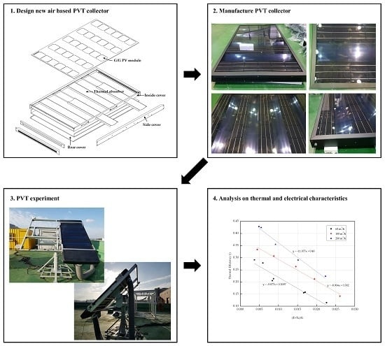
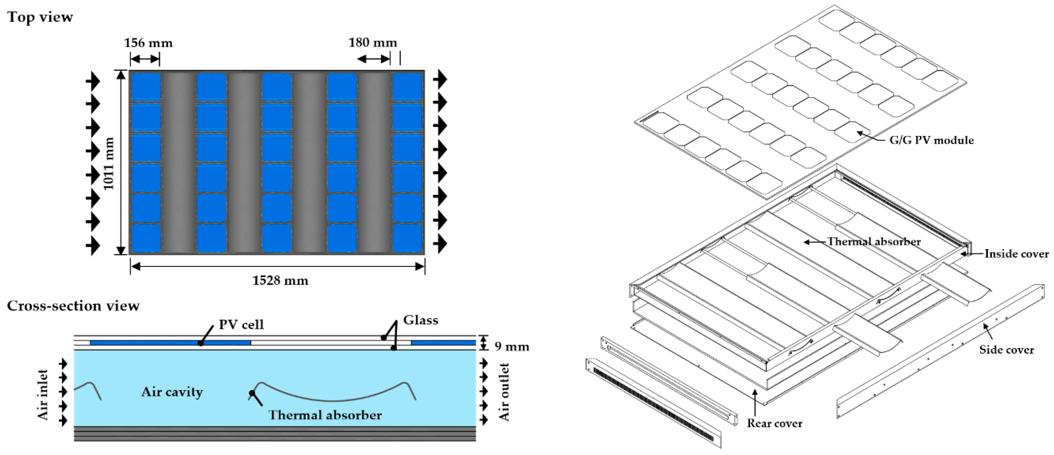
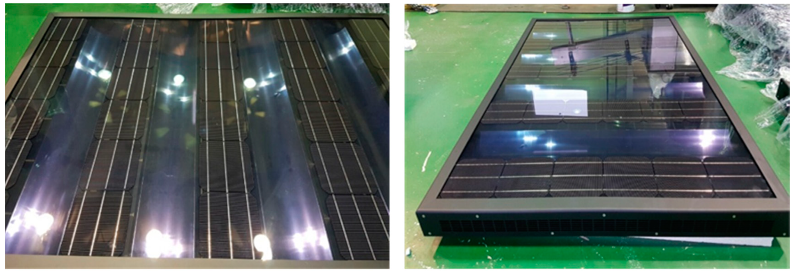
2. New Air PVT Collector

In previous studies, PVT collectors consisted of PV cells throughout the front side [3,5,19]. Also, baffles were fitted inside the collector, mainly to extend the flow path of the heat medium to increase the thermal performance. In this study, a new air-based PVT collector was proposed and designed to address one of the challenges of PVT collector performance between thermal and electrical yield, as shown in Figure 1 and Figure 2. The glass-to-glass type PV module was attached to the front of the PVT collector and was also designed to capture more solar heat inside the collector by maintaining a constant gap between the PV cells. Inside the PVT collector, four equally spaced heat absorbing plates with high thermal conductivity were installed between the PV cells. The plates were made of aluminum (with a length of 980 mm and a width of 194 mm) with a highly selective blue coating and were designed to directly harness solar radiation coming in through the glass surface. The heat absorbing plate installed inside the PVT collector was designed as a round shape to obtain more solar radiation by increasing the area of the absorber, such that the internal temperature of the collector could be increased to improve the thermal performance. The plates were located in the air cavity behind the glass-to-glass PV module, such that air could circulate above and below the thermal absorbers. Moreover, the bending shaped plate was considered to act as a baffle, lengthening the air flow path inside the collector and creating turbulence in the collector. Consequently, the heat transfer of the collector increases and the surface temperature of the PV module reduces. By maintaining a lower temperature for the PV module, the degradation of PV power from temperature rise can be prevented. The area of the PVT collector was 1.63 m2 and detailed specifications of the attached PV module are shown in Table 1.

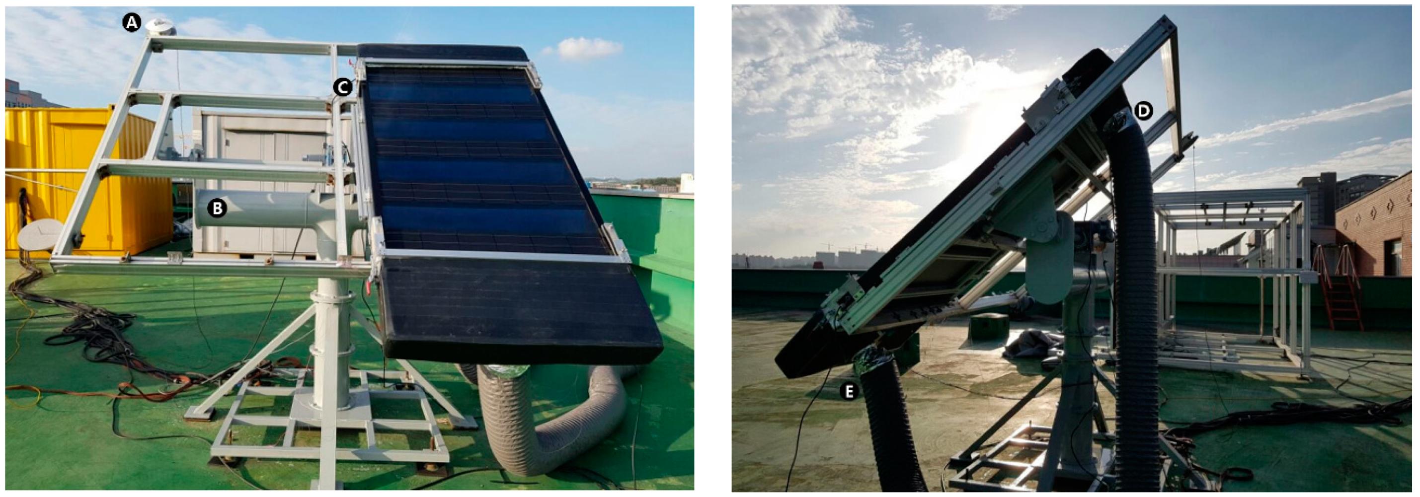
3. Experimental Setup

The developed PVT collectors were evaluated based on ISO 9806:2017, as mentioned before. The collectors were installed on a 2-axis tracker with horizontal (0 to 160°) and vertical (15 to 90°) angle adjustments (see Figure 3) in Cheonan, Republic of Korea (36.815° N, 127.114° E). The tracker was set such that the PVT was always directly normally aligned with the sun. To evaluate the thermal performance of the air-based PVT collector, parameters such as the temperature and flow rate at the inlet and outlet, the solar irradiance, and the outdoor temperature were measured at 10 s intervals. Further, to analyze the electrical performance of the collector, the PV power, maximum and open-circuit voltage, and the current were also measured. The experiment was conducted at a solar radiation amount of 700 W/m2 or more, in accordance with the test method of ISO 9806:2017. The experiment was conducted from November to December in 2017. The data were collected when the solar radiation amount, the flow rate, the temperature at the inlet and outlet, the outdoor temperature and the surrounding air speed were in steady state. The data were measured when the steady-state conditions within the ranges given in Table 2 were met [18]. The specifications and uncertainty values of the instruments used are presented in Table 3.

4. Result and Analysis

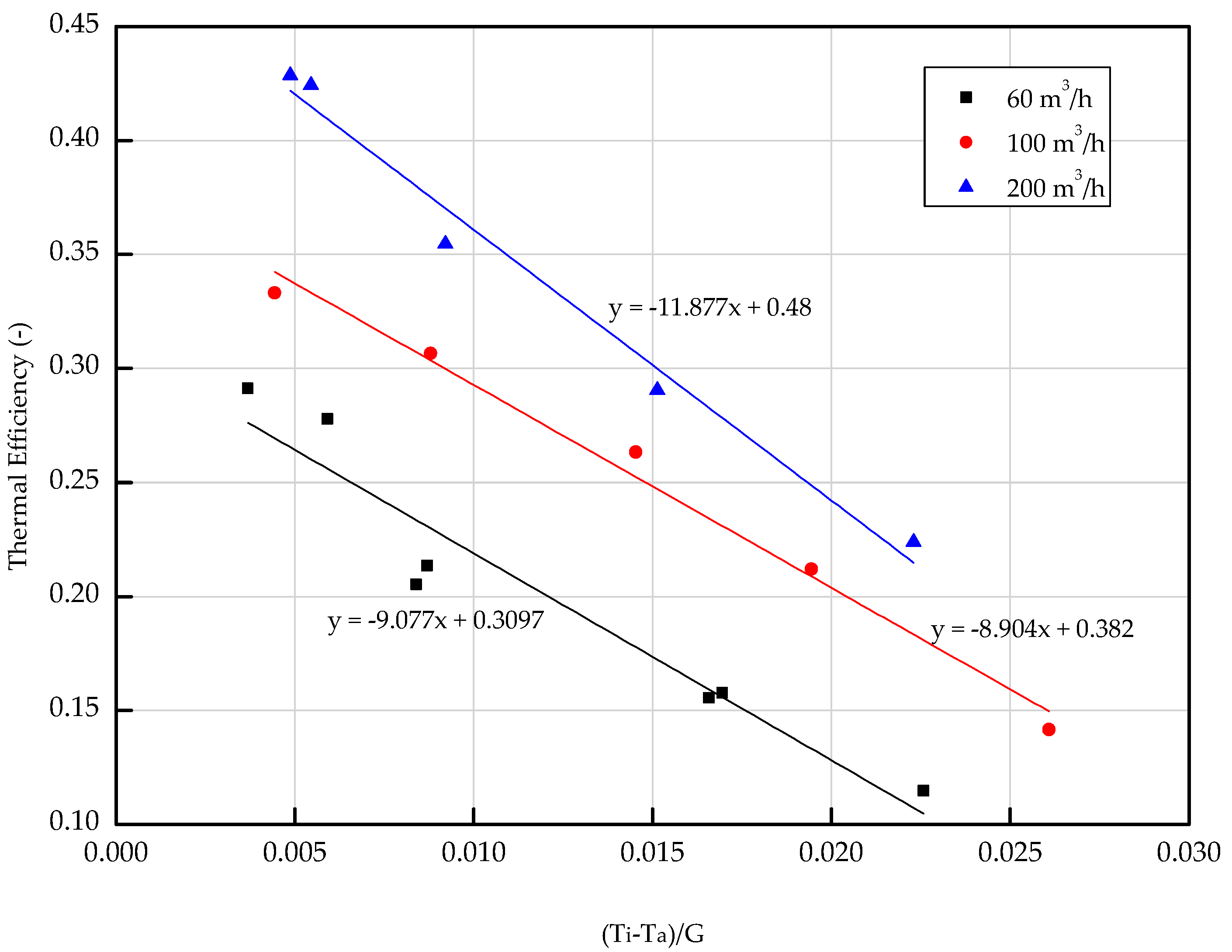
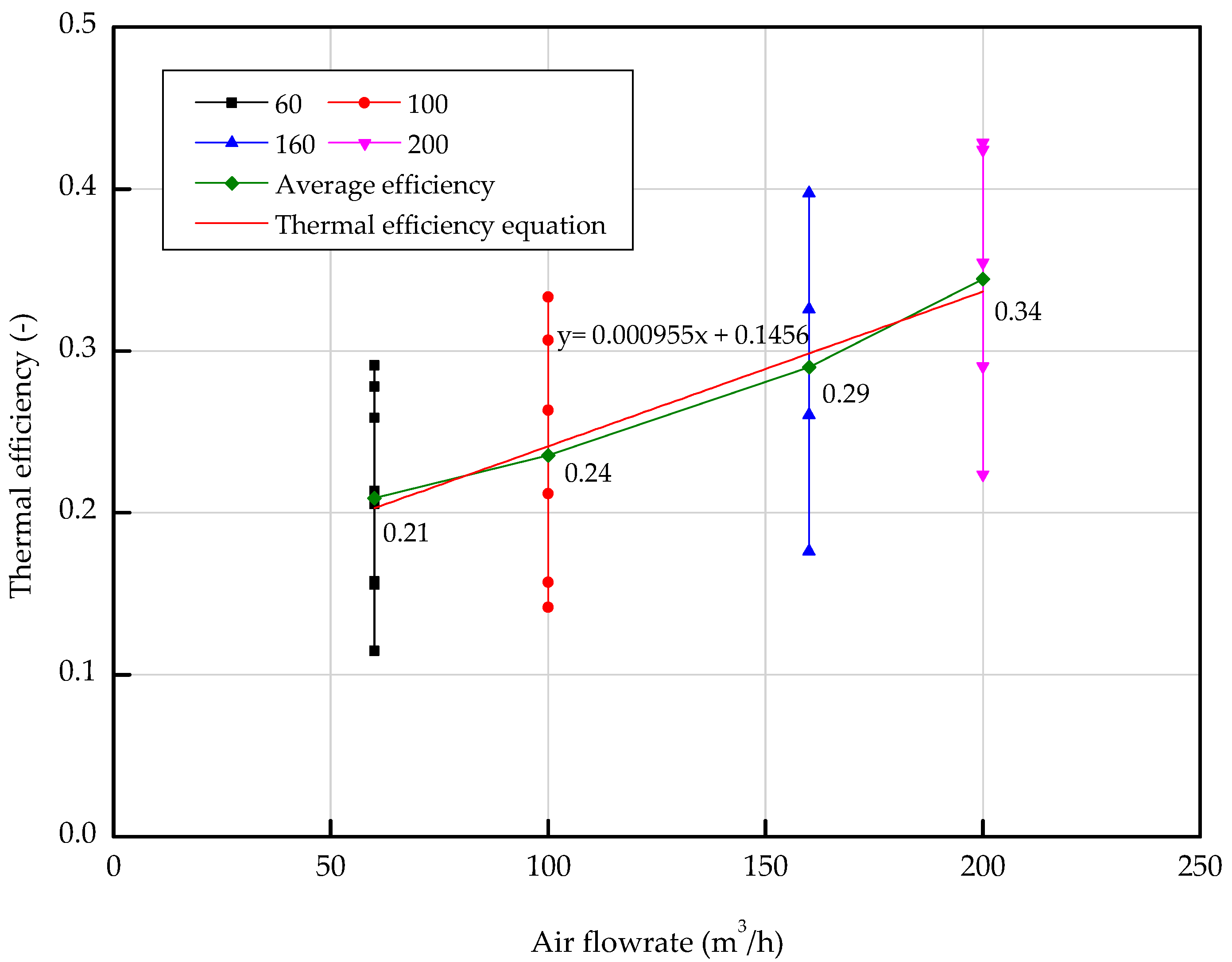
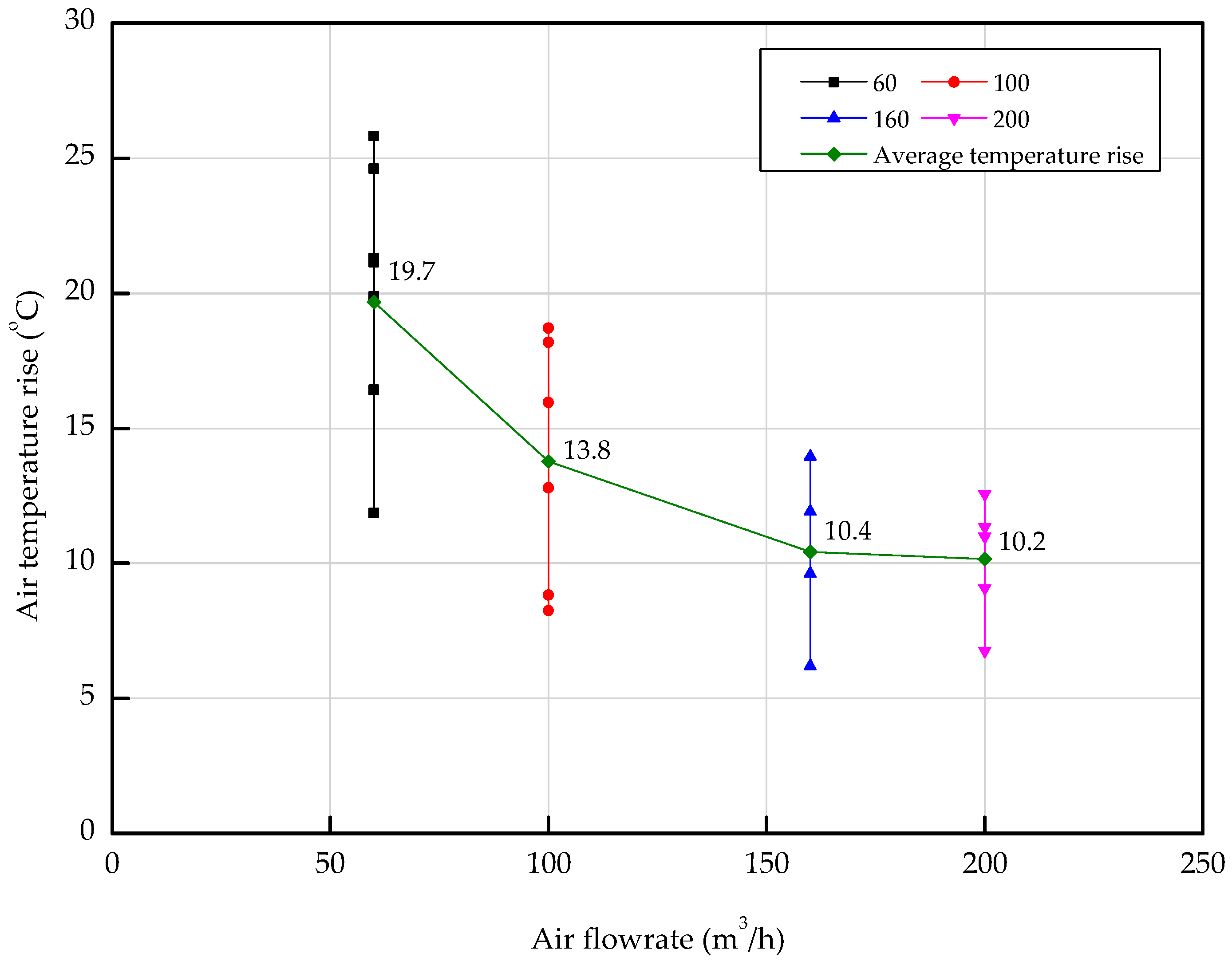
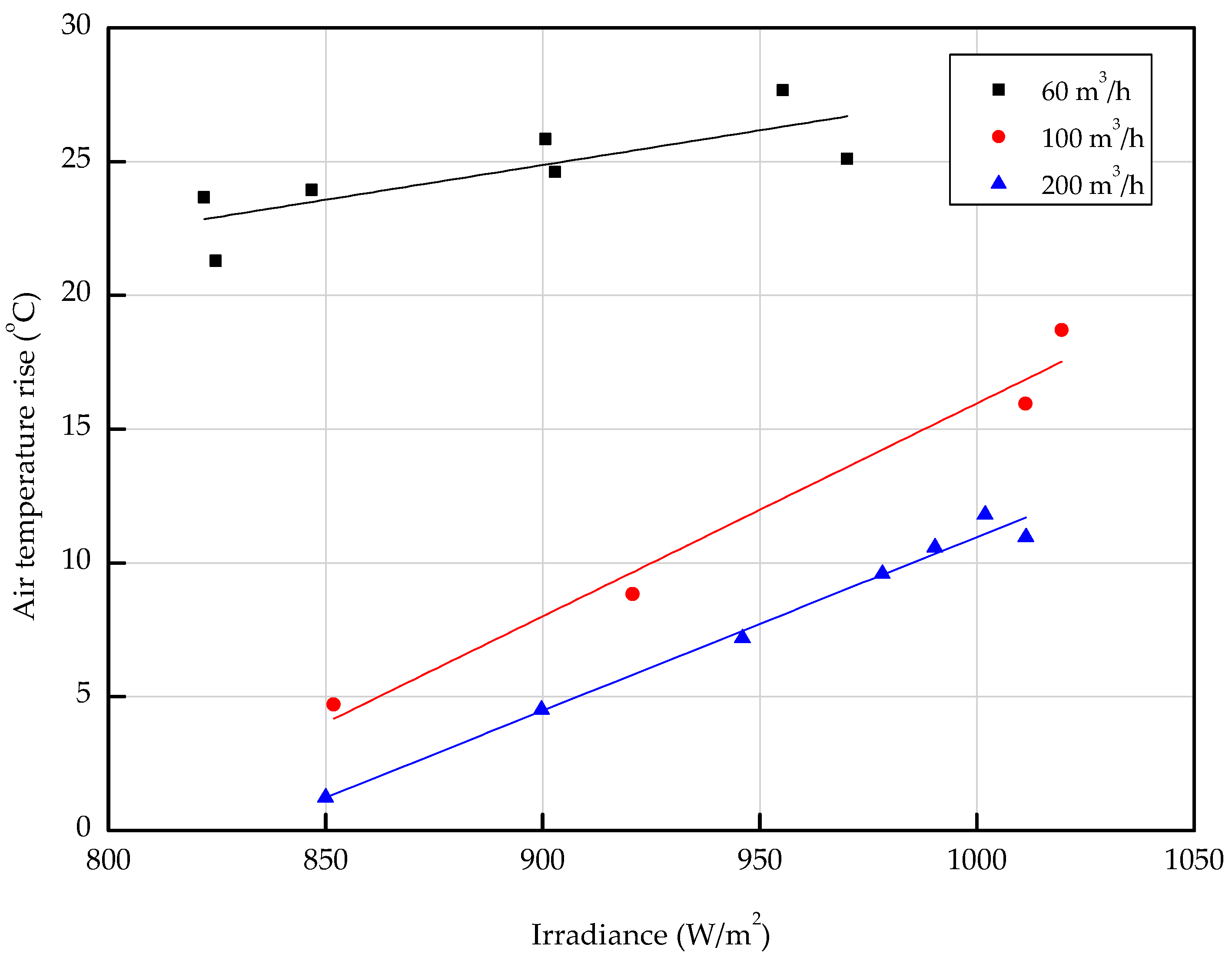
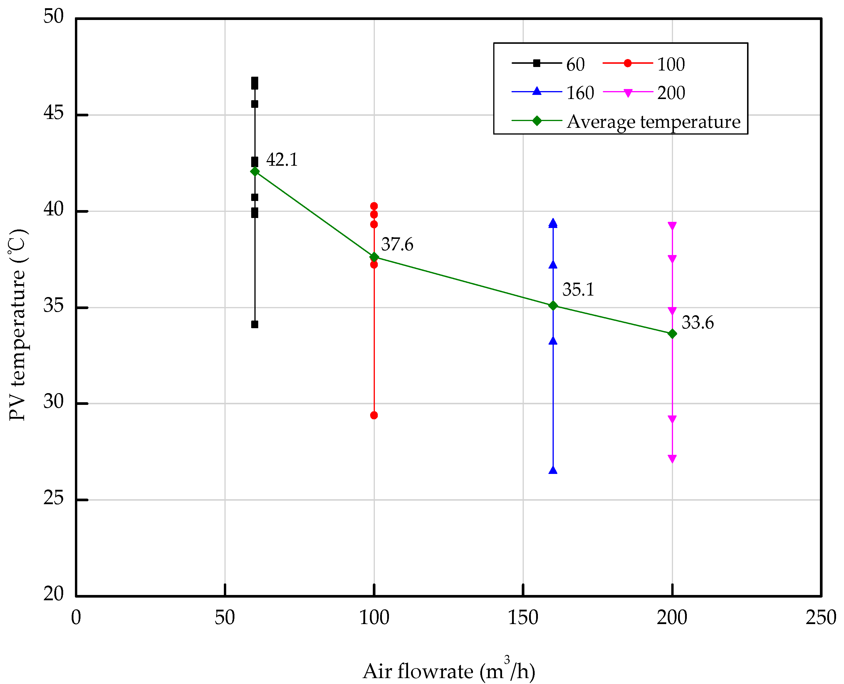
4.1. Thermal Characteristics

The thermal efficiency was estimated by Equation (1) to evaluate the thermal performance [18]:
η t h =   m C p ( T o T i ) A p v t G
In Equation (1), η t h , m , C p , T o , T i , A p v t , and G are thermal efficiency (-), flow rate (m3/h), specific heat (−J/kg∙K), outlet temperature (°C), inlet temperature(°C), area of PVT collector (m2) and global solar radiation (W/m2), respectively. The experimental data were measured at an average solar radiation and outdoor temperature of 956 W/m2 and 0.2 °C, respectively. The thermal characteristics of the air-based PVT collector were analyzed by the thermal efficiency and air temperature rise between the inlet and outlet with respect to the flow rate. The thermal efficiency for various air flow rates is depicted in Figure 4. The thermal efficiency decreased with increasing air inlet flow rate. The maximum thermal efficiencies were 48%, 38.2%, and 30.97% for 60 m3/h, 100 m3/h, and 200 m3/h air flow rates, respectively. Figure 5 presents the relationship of thermal efficiency according to the inlet flow rate. The graph shows different points of thermal efficiency on the same flow rate. These resulted from different inlet air temperatures. In the experiment, the inlet temperature of the air was set up in the range of 0–25 °C, and a lower inlet temperature caused higher thermal efficiency for the same flow rate. Even though the inlet flow rate was the same, different inlet temperatures affected the thermal efficiency of the PVT collector. The different inlet temperatures also affected the temperature rise between the inlet and outlet. The results showed that the average thermal efficiency gradually increased to 21%, 22%, 29%, and 34% as the inlet air flow rate increased to 60 m3/h, 100 m3/h, 160 m3/h, and 200 m3/h, correspondingly. When the flow rate of the collector increased to 60–200 m3/h, the maximum thermal efficiency increased to about 29–42%, which represented a 13% increase in thermal efficiency. Also, the thermal efficiency of the PVT collector was different, even though the flow rate was same according to the inlet temperature, outdoor temperature and the solar radiation. Figure 6 depicts the air temperature rise between the inlet and outlet of the PVT collector, according to the inlet air flow rate. When the inlet flow rates of the PVT collector were 60 m3/h, 100 m3/h, 160 m3/h, and 200 m3/h, the average air temperature rise was 19.7 °C, 13.8 °C, 10.4 °C, and 10.2 °C, correspondingly. The rise in air temperature between the inlet and outlet of the PVT collector decreased as the inlet flow increased. Thus, trends for air temperature rise with air flow rate, in contrast with the relationship of thermal efficiency with the air flow rate. Figure 7 shows a graph of the rise in air temperature at both the inlet and outlet of the PVT collector due to solar radiation, and is plotted according to inlet flow rates of 60 m3/h, 100 m3/h, and 200 m3/h. The graph shows that the higher the solar radiation, the higher the air temperature rise of the PVT collector. At similar solar irradiance, a lower inlet flow rate of the PVT collector resulted in a higher air temperature rise. It can be deduced that higher solar radiation enabled more heat acquisition for the PVT collector. Also, the lower the inlet flow rate, the slower the flow velocity, which resulted in the higher temperature of air passing through the PVT collector.

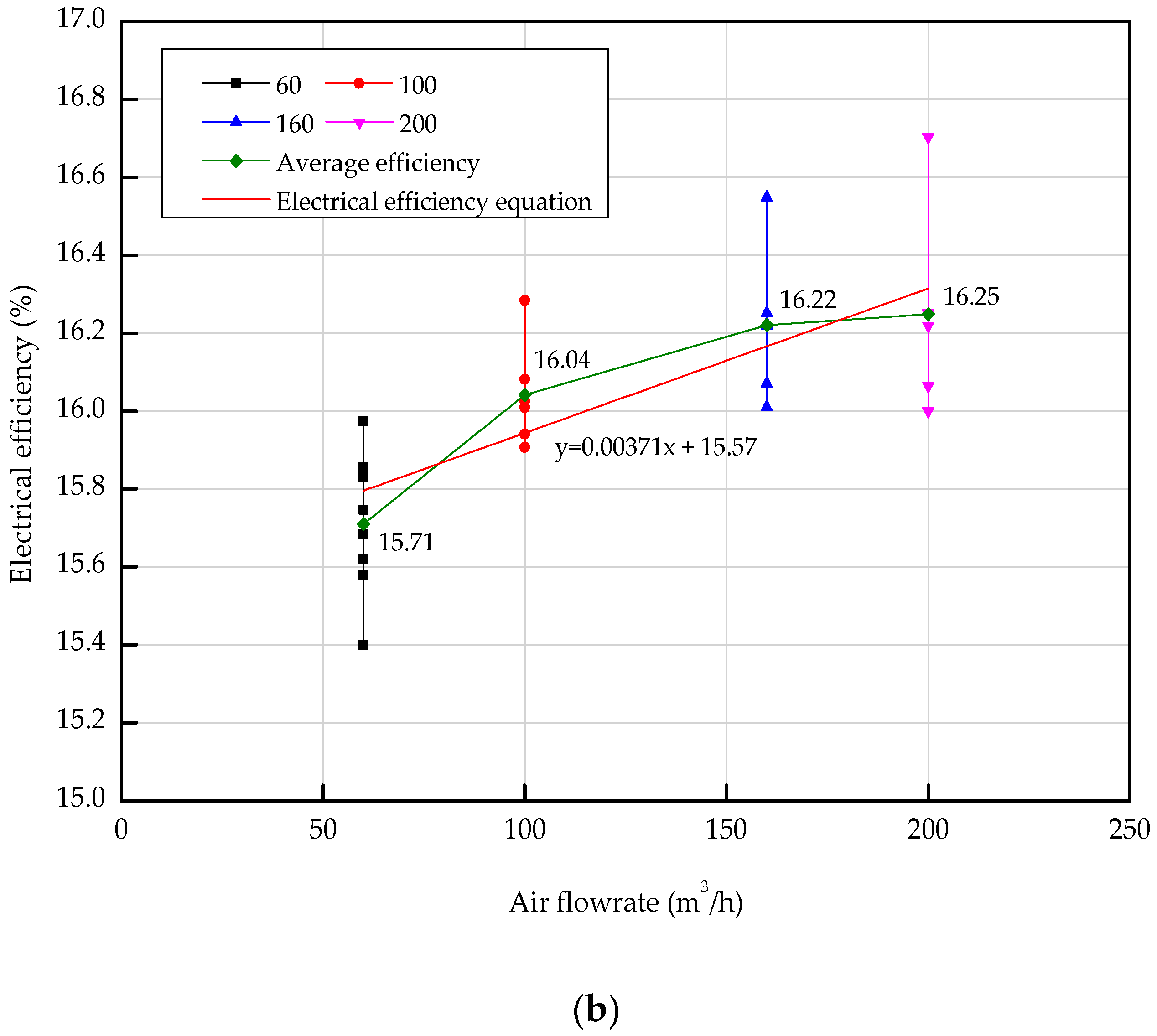
4.2. Electrical Characteristics

Figure 8 illustrates the effect of solar radiation on the PV module power and surface temperature. The graph shows that the air-based PVT collector increased the output of the PV module as the solar irradiance increased, like a normal PV module. In the case of a PV module, the surface temperature of the PV module increases when solar radiation increases [19]. On the other hand, for the PVT collector, the surface temperature of the PV module was maintained or reduced, depending on the operating conditions, even if the solar radiation was increased. Figure 9 shows a graph of PV power and solar radiation with the PV module surface temperature. From Figure 9, the PV power decreased as PV module temperature increased. Figure 10 shows a graph showing the open-circuit voltage and maximum voltage according to the temperature of the PV module. Figure 10 indicates the reason for power reduction due to the temperature rise of the PV module. The results show that the higher the temperature of the PV module, the lower the PV voltage. As the temperature of the PV module increased, the PV voltage decreased, and in effect the PV power generation decreased. Figure 9 shows that the PV temperature was maintained well below 30 °C when the solar radiation was more than 1000 W/m2 and the PV power generation was about 120 W. Even when the PV module power was close to the standard test condition (STC) condition of 123.3 W, the PV temperature was kept below 30 °C. In the case of a normal PV system, the nominal operating cell temperature (NOCT), which is an index indicating the temperature of the PV module, is 40 °C or higher when a general PV module operates (with a solar radiation of 800 W/m2, outdoor temperature of 20 °C, and wind speed of 1 m/s) [20,21]. In the PVT system, the temperature of the PV module was analyzed to be about 10 °C lower than NOCT of the general PV module, depending on the given operation condition. The experimental results show that the air-based PVT collector has a different surface temperature and power generation than that of the PV module, depending on the operating conditions of the fluid temperature. Therefore, it can be inferred that the PVT system can prevent the increase of the surface temperature of PV module according to the operating conditions, thereby preventing the power decrease due to the temperature rise.
The electrical efficiency of the PVT collector can be derived using the following mathematical equation [22]:
η e l = I m V m A p v G
where η e l , I m , V m , A p v , and G are the electrical efficiency (-), maximum current (A), maximum voltage (V), area of the PV cell (m2), and global solar radiation (W/m2), respectively. The electrical efficiency of the PVT collector was confirmed by the decreasing trend as the PV temperature rose, as shown in Figure 11a. The increase in PV temperature caused the reduction in PV electrical efficiency. Figure 11b shows the effect of flow rate on the electrical efficiency of the PVT collector. From the graph, the electrical efficiency and inlet flow rate of the PVT increase concurrently. When the flow rate was 60 m3/h, the average electrical efficiency of the PVT collector was 15.7%, but the average electrical efficiency increased to about 16.3% at an inlet flow rate of 200 m3/h. The reason why the electrical efficiency increased with the increase of the inlet flow of the PVT collector can be deduced from Figure 12, which shows a temperature graph of the PV module against the inlet flow rate of the PVT collector. Figure 12 shows that the average temperature of the PV module decreased to 42.07–33.64 °C as the inlet flow rate of the PVT collector increased to 60–200 m3/h. When the inlet flow rate of the PVT collector increased to 60–200 m3/h, the temperature of the PV module decreased by 8.43 °C, and the electrical efficiency increased by 0.6%. Subsequently, the increased inlet flow rate of the PVT collector in turn increased the internal flow velocity, causing the decreased temperature of the PV module. The experimental results thoroughly confirm that the flow rate and temperature of the inlet can affect not only thermal performance, but also the electrical performance of the PVT collector.

5. Conclusions

In this study, a new type of PVT collector was designed and fabricated, and its thermal and electrical performance was analyzed through experiments. The thermal and electrical characteristics of the air-based PVT collector, according to the collector inlet flow rate, solar radiation, and PV temperature were investigated. The key results can be summarized as follows:
(1)
The air-based PVT collector was found to have a thermal efficiency of about 26–45% when the inlet flow rate increased to 60–200 m3/h at an average solar irradiance of 950 W/m2 and an outdoor temperature of 0 °C. As the inlet flow rate of the air-based PVC collector increased, the inlet and outlet temperature rise of the PVT collector gradually decreased to 11.4–25.8 °C. The thermal efficiency of an air-based PVT collector is proportional to the flow rate of the heat medium that transfers the heat and the temperature difference between inlet and outlet of collector. In particular, the flow rate of the heat medium has a greater effect on the thermal efficiency increase of the air-based PVT collector.
(2)
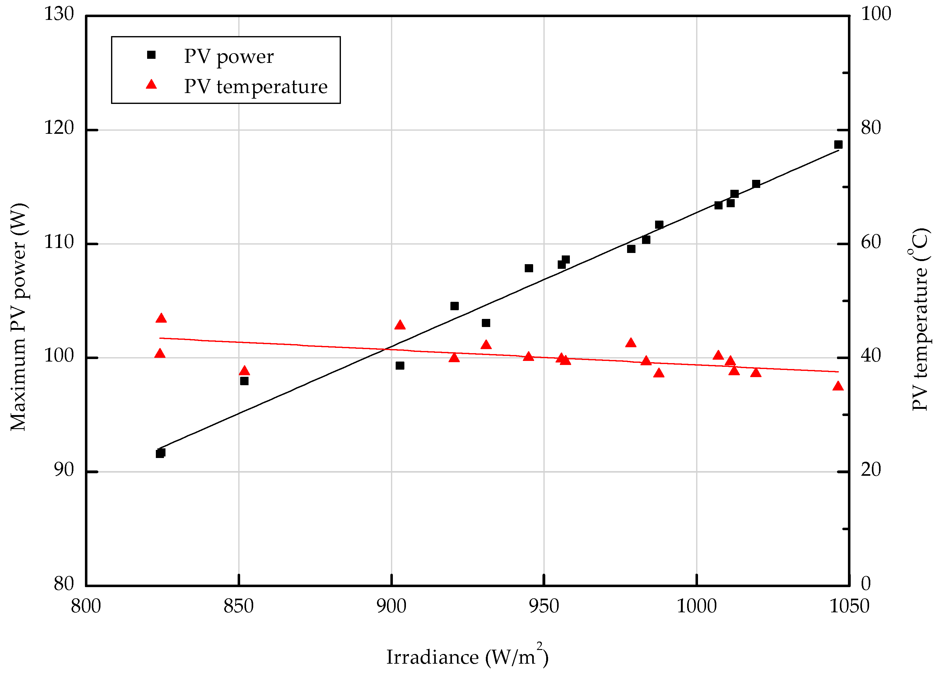
For the air-based PVT collector, the power generation increased as the solar radiation increased. However, it was confirmed that the surface temperature of the PV module does not increase even if the solar radiation increases according to the operating conditions of the air-based PVT collector. The system did not show a significant increase in PV temperature during the production of electricity while producing heat, depending on the heat collection characteristics. It was confirmed that the PV temperature was kept below 30 °C under the maximum power generation conditions.
(3)
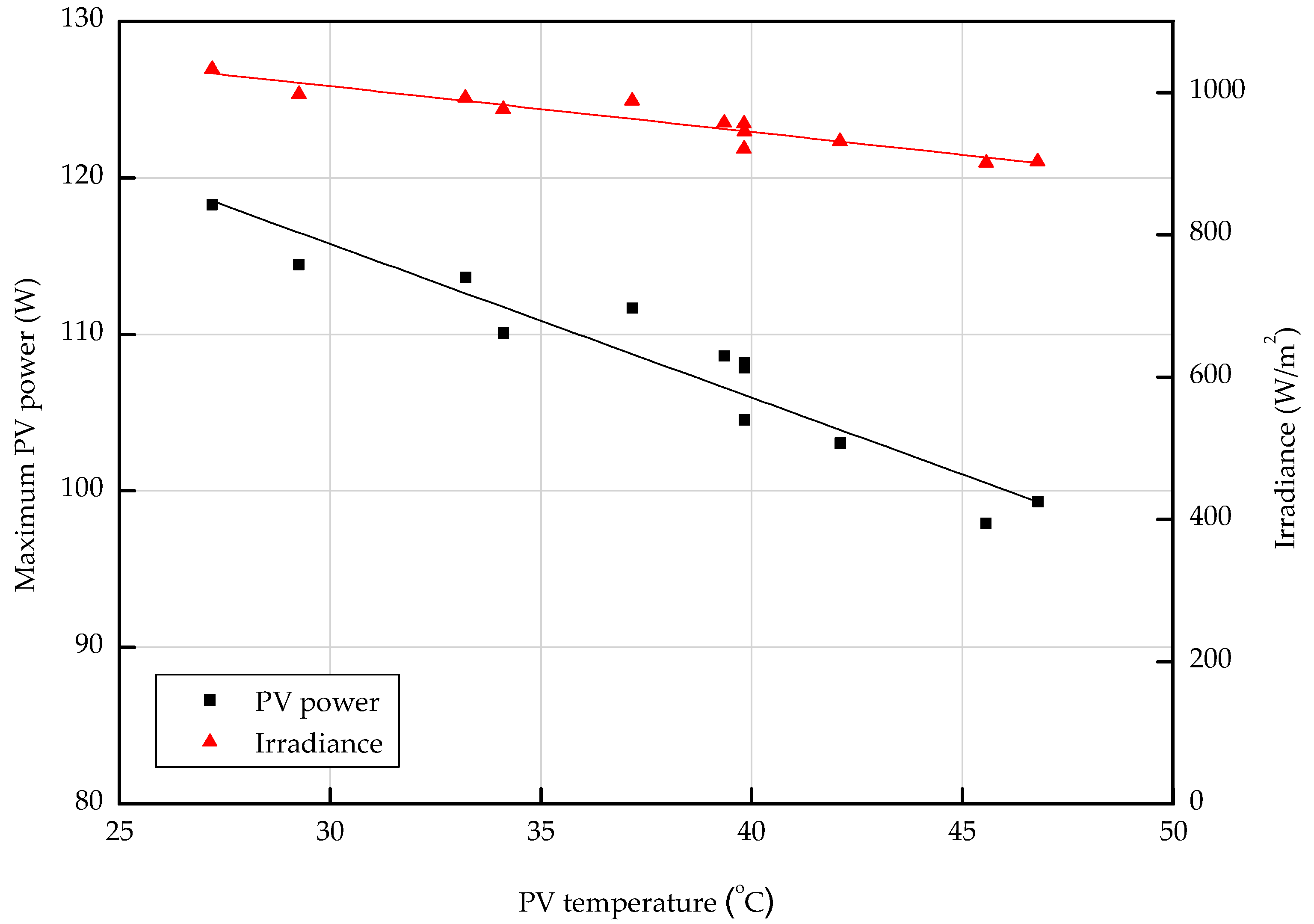
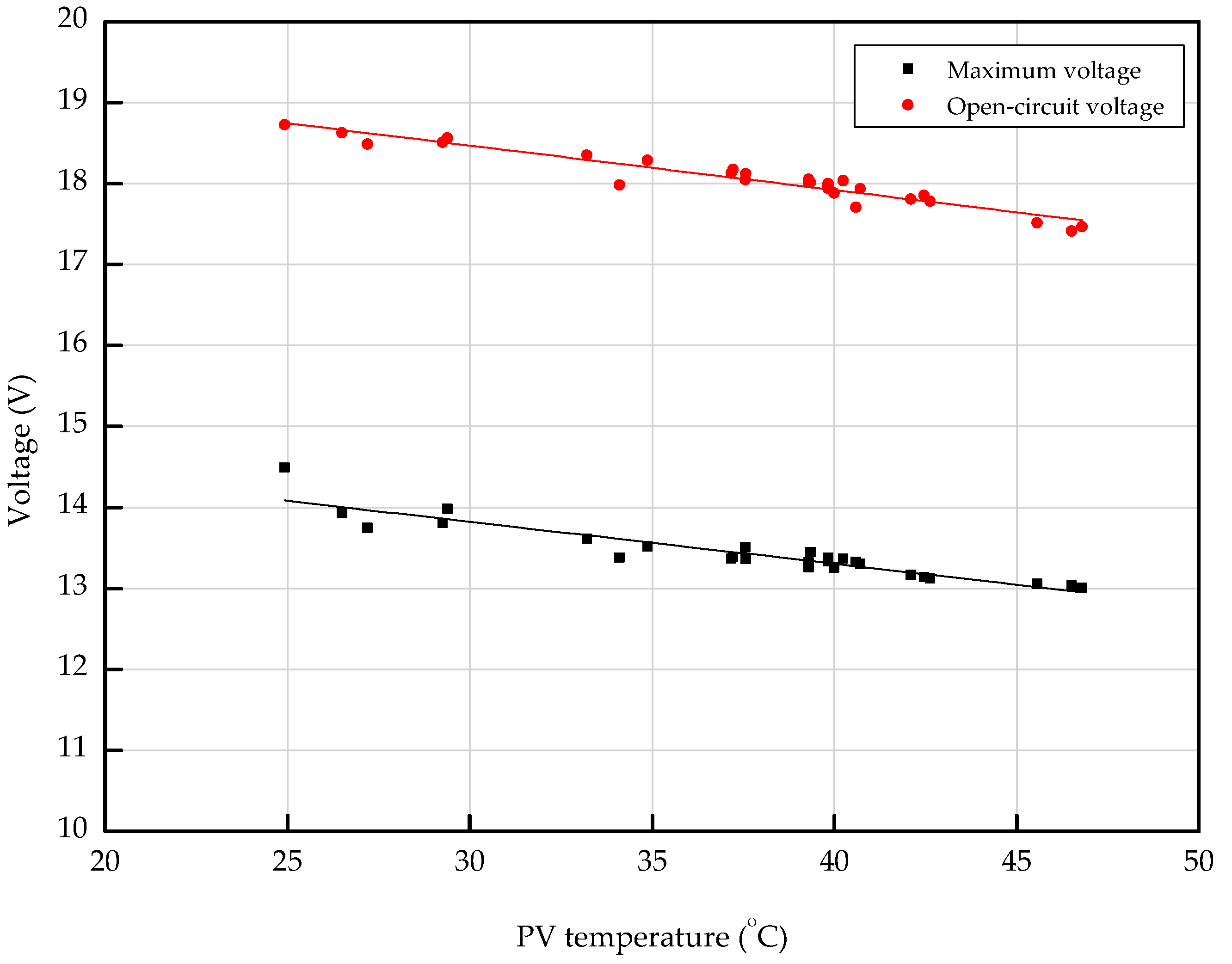
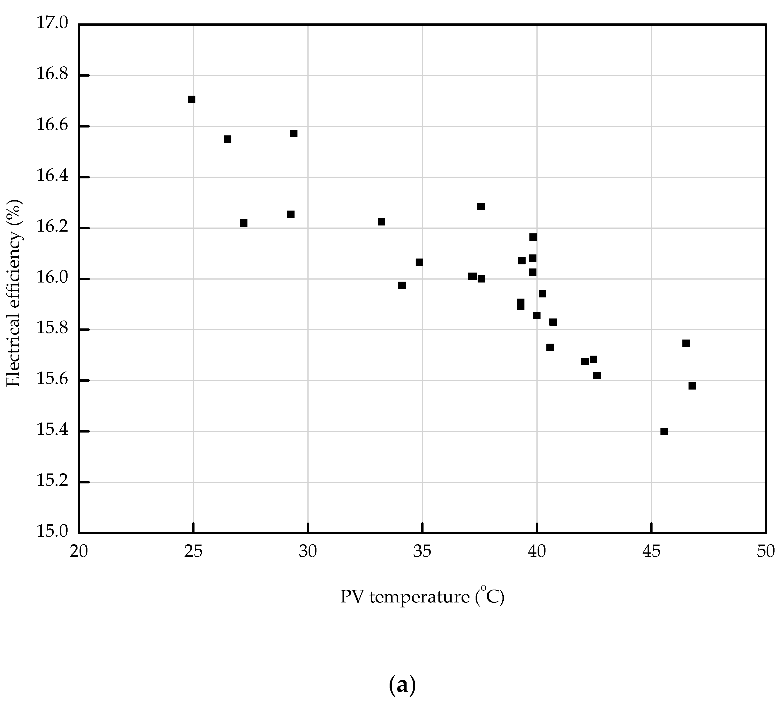
The results proved that the temperature of the PV module decreased as the inlet flow rate increased, thereby preventing the power reduction of the PV module due to temperature rise and consequently improving the electrical efficiency.
Through these results, it can be seen that the design and operation of air-based PVT collectors needs to consider the supply temperature and the flow rate required for heating in the building when combined with the building system, and it is expected this study can be used as a foundation for further study on the optimum operation of PVT systems.

Author Contributions

Conceptualization, J.-T.K., and J.-H.K.; methodology, J.-H.K., and S.-M.K.; software, S.-M.K.; validation, J.-T.K., J.-H.K. and S.-M.K.; formal analysis, S.-M.K.; investigation, J.-H.K. and S.-M.K.; resources, J.-T.K.; data curation, J.-H.K. and S.-M.K.; writing—original draft preparation, S.-M.K.; writing—review and editing, J.-T.K., J.-H.K. and S.-M.K.; visualization, J.-H.K. and S.-M.K.; supervision, J.-T.K.; project administration, S.-M.K.; funding acquisition, J.-T.K. and J.-H.K.

Funding

This research was funded by the Korea Institute of Energy Technology Evaluation and Planning (KETEP) and the Ministry of Trade, Industry and Energy (MOTIE) of the Republic of Korea, grant number 20188550000480 and 20173010013420.

Conflicts of Interest

The authors declare no conflict of interest.

Nomenclature

A p v Area of PV cell, m2
A p v t Area of PVT, m2
C p Specific heat, J/kg∙K
G Global solar radiation, W/m2
I m Maximum current, A
T a Ambient temperature, °C
T i Inlet temperature, °C
T o Outlet temperature, °C
V m Maximum voltage, V
m Air flow rate, m3/h
η e l Electrical efficiency, (-)
η t h Thermal efficiency, (-)

References

  1. Sathe, T.M.; Dhoble, A.S. A review on recent advancements in photovoltaic thermal techniques. Renew. Sustain. Energy Rev. 2017, 76, 645–672. [Google Scholar] [CrossRef]
  2. Kim, J.H.; Kim, J.T. A Literature Review on Hybrid PV/Thermal Air Collector in terms of its Design and Performance. J. Korean Sol. Energy Soc. 2014, 34, 30–41. [Google Scholar] [CrossRef]
  3. Euh, S.H.; Lee, J.B.; Choi, Y.S.; Kim, D.H. The performance and Efficiency Analysis of a PVT System Compared with a PV module and a Solar collector. J. Korean Sol. Energy Soc. 2012, 32, 1–10. [Google Scholar] [CrossRef]
  4. Jia, Y.; Alva, G.; Fang, G. Development and applications of photovoltaic-thermal systems: A review. Renew. Sustain. Energy Rev. 2019, 102, 249–265. [Google Scholar] [CrossRef]
  5. Kim, J.H.; Park, S.H.; Kim, J.T. Experimental Performance of a Photovoltaic-thermal Air Collector. Energy Procedia 2014, 48, 888–894. [Google Scholar] [CrossRef] [Green Version]
  6. Mellor, A.; Alvarez, D.A.; Guarracino, I.; Ramos, A.; Lacasta, A.R.; Llin, L.F.; Murrell, A.J.; Paul, D.J.; Chemisana, D.; Markides, C.N.; et al. Roadmap for the next-generation of hybrid photovoltaic-thermal solar energy collector. Sol. Energy 2018, 174, 386–398. [Google Scholar] [CrossRef]
  7. Riffat, S.B.; Cuce, E. A review on hybrid photovoltaic/thermal collectors and systems. Int. J. Low-Carbon Technol. 2011, 6, 212–241. [Google Scholar] [CrossRef] [Green Version]
  8. Hasan, M.A.; Sumathy, K. Photovoltaic thermal module concepts and their performance analysis: A review. Renew. Sustain. Energy Rev. 2010, 14, 1845–1859. [Google Scholar] [CrossRef]
  9. Hu, J.; Sun, X. Numerical analysis of mechanical ventilation solar air collector with internal baffles. Energy Build. 2013, 62, 230–238. [Google Scholar] [CrossRef]
  10. Singh, H.P.; Jain, A.; Singh, A.; Arora, S. Influence of absorber plate shape factor and mass flow rate on the performance of the PVT system. Appl. Therm. Eng. 2019, 156, 692–701. [Google Scholar] [CrossRef]
  11. Slimani, M.E.A.; Amirat, M.; Kurucz, I.; Bahria, S.; Hamidat, A.; Chaouch, W.B.; Slimani, M.E.A. A detailed thermal-electrical model of three photovoltaic/thermal (PV/T) hybrid air collectors and photovoltaic (PV) module: Comparative study under Algiers climatic conditions. Energy Convers. Manag. 2017, 133, 458–476. [Google Scholar] [CrossRef]
  12. Yang, T.; Athienitis, A.K. A study of design options for a building integrated photovoltaic/thermal (BIPV/T) system with glazed air collector and multiple inlets. Sol. Energy 2014, 104, 82–92. [Google Scholar] [CrossRef]
  13. Dubey, S.; Tay, A.A. Testing of two different types of photovoltaic–thermal (PVT) modules with heat flow pattern under tropical climatic conditions. Energy Sustain. Dev. 2013, 17, 1–12. [Google Scholar] [CrossRef]
  14. Tiwari, S.; Agrawal, S.; Tiwari, G.N. PVT air collector integrated greenhouse dryers. Renew. Sustain. Energy Rev. 2018, 90, 142–159. [Google Scholar] [CrossRef]
  15. Herrando, M.; Pantaleo, A.M.; Wang, K.; Markides, C.N. Solar combined cooling, heating and power systems based on hybrid PVT, PV or solar-thermal collectors for building applications. Renew. Energy 2019, 143, 637–647. [Google Scholar] [CrossRef]
  16. Sakellariou, E.; Axaopoulos, P. An experimentally validated, transient model for sheet and tube PVT collector. Sol. Energy 2018, 174, 709–718. [Google Scholar] [CrossRef]
  17. Guarracino, I.; Freeman, J.; Ramos, A.; Kalogirou, S.A.; Ekins-Daukes, N.J.; Markides, C.N. Systematic testing of hybrid PV-thermal (PVT) solar collectors in steady-state and dynamic outdoor conditions. Appl. Energy 2019, 240, 1014–1030. [Google Scholar] [CrossRef]
  18. International Organization for Standard. BS EN ISO 9806:2017 Solar Energy-Solar Thermal Collectors-Test Methods; BSI: London, UK, 2017; ISBN 978 0 580 93683 8. [Google Scholar]
  19. Kang, J.G.; Kim, J.H.; Kim, J.T. A Study on the Performance Comparisons of Air Type BIPVT Collector Applied on Roofs and Facades. J. Korean Sol. Energy Soc. 2010, 30, 56–62. [Google Scholar]
  20. Kamuyu, W.C.L.; Lim, J.; Won, C.; Ahn, H. Prediction Model of Photovoltaic Module Temperature for Power Performance of Floating PVs. Energies 2018, 11, 447. [Google Scholar] [CrossRef]
  21. Kim, K.S.; Kang, G.H.; Yu, G.J.; Yoon, S.G. Roof-attached Crystalline Silicon Photovoltaic Module’s Thermal Characteristics. J. Korean Sol. Energy Soc. 2012, 32, 11–18. [Google Scholar] [CrossRef]
  22. International Electrotechnical Commission. IEC 61215:2016, Crystalline Silicon Terrestrial Photovoltaic (PV) Modules—Design Qualification and Type Approval; International Electrotechnical Commission: London, UK, 2016. [Google Scholar]
Figure 1. Prototype design and schematic diagram of new photovoltaic thermal (PVT) collector.
Energies 12 02661 g001
Figure 2. Designed PVT collector.
Energies 12 02661 g002
Figure 3. Experimental set up of the air-based PVT collector. (A) Pyrometer. (B) Tracker. (C) PVT collector. (D) Outlet. (E) Inlet.
Energies 12 02661 g003
Figure 4. Thermal efficiency for different air flow rates.
Energies 12 02661 g004
Figure 5. Effect of the air flow rate on the thermal efficiency.
Energies 12 02661 g005
Figure 6. Effect of the air flow rate on the rise in air temperature between inlet and outlet.
Energies 12 02661 g006
Figure 7. Effect of solar irradiance on air temperature rise between inlet and outlet for different air flow rates.
Energies 12 02661 g007
Figure 8. Effect of solar radiation on PV power and temperature.
Energies 12 02661 g008
Figure 9. Effect of PV temperature on PV power and temperature.
Energies 12 02661 g009
Figure 10. Effect of PV temperature on voltage.
Energies 12 02661 g010
Figure 11. Effect of (a) PV temperature and (b) air flow rate on electrical efficiency.
Energies 12 02661 g011aEnergies 12 02661 g011b
Figure 12. Effect of air flow rate on PV temperature.
Energies 12 02661 g012
Table 1. PVT module specification.
Cell TypeMonocrystalline Silicon
Photovoltaic (PV) cell efficiency17.29%
Maximum power123.3 W
Maximum voltage15.08 V
Maximum current8.18 A
Open voltage19.05 V
Short current8.61 A
Collector size1584 × 1031 × 84.5 mm
Table 2. Permitted deviation of the measured parameters during the measurement period.
ParameterPermitted Deviation from the Mean Value
Liquid Heating CollectorAir Heating Collector
Hemispherical solar irradiance±50 W/m2
Thermal irradiance (WISC * only)±20 W/m2
Ambient air temperature±1.5 K
Fluid mass flow rate±1%±2%
Fluid temperature at the collector inlet±0.1 K±1.5 K
Fluid temperature at the collector outlet±0.4 K±1.5 K
Surrounding air speed±1.0 m/s deviation from set value
* WISC—wind and irradiance sensitive collectors.
Table 3. Specifications of the measuring equipment.
ParameterSpecification
Solar irradianceInstrument: Pyranometer
Model: Albedometer
Operating temperature: −40 °C to 80 °C
Measurement range: 0–2000 W/m2
Non-linearity: ±1.2% at <1000 W/m2
Directional response: ± 20 W/m2 at 1000 W/m2
Flow rate (inlet and outlet)Instrument: Insertion Mass Flow Meter
Model: Steel Mass 640 S
Operating temperature: −20 °C to 50 °C
Measurement range: 0–200 m3/h
Accuracy: ±1% of reading +0.5% of full scale
Temperature and relative humidity
(inlet and outlet duct, outdoor)
Instrument: Humidity and temperature transmitter
Model: Humidity Transmitter HF 5
Operating temperature: −40 °C to 60 °C/0–100% rh
Measurement range: −50 °C to 100 °C/0–100% rh
Accuracy: ±0.8% rh/0.1 K at 23 °C
PVT temperature
(inlet and outlet of PVT, PVT module)
Instrument: Thermocouple
Manufacture: Omega T type thermocouple
Measurement range: −250 °C to 350 °C
Accuracy: ±0.5 °C

