Input Disturbance Suppression for Unidirectional Matrix Converter with a Stability-Enhancing Modulation Scheme


Abstract
:
1. Introduction
2. Modulation Schemes for the UMC
2.1. Traditional Modulation Scheme
2.2. Stability-Enhancing Modulation Scheme
3. Proposed Feedback Control Strategy and Stability Analysis
3.1. Feedback Control of Output Current Amplitude
3.2. Stability Analysis
4. Experimental Verification
5. Conclusions
Author Contributions
Funding
Conflicts of Interest
Appendix A
References
- Empringham, L.; Kolar, J.W.; Rodriguez, J.; Wheeler, P.W.; Clare, J.C. Technological Issues and Industrial Application of Matrix Converters: A Review. IEEE Trans. Ind. Electron. 2013, 60, 4260–4271. [Google Scholar] [CrossRef]
- Rząsa, J. An Alternative Carrier-Based Implementation of Space Vector Modulation to Eliminate Common Mode Voltage in a Multilevel Matrix Converter. Electronics 2019, 8, 190. [Google Scholar] [CrossRef]
- Song, W.; Liu, J.; Sun, X.; Wu, F.; Gao, D.; Wang, Y. Research on Commutation and Coordination Control Strategy of Excitation Power Supply Based on Bidirectional Reduced Matrix Converter for Ion Accelerator. Energies 2018, 11, 3396. [Google Scholar] [CrossRef]
- Merchan-Villalba, L.; Lozano-Garcia, J.; Gutierrez-Torres, D.; Avina-Cervantes, J.; Pizano-Martinez, A. Four-Step Current Commutation Strategy for a Matrix Converter Based on Enhanced-PWM MCU Peripherals. Electronics 2019, 8, 547. [Google Scholar] [CrossRef]
- Szczesniak, P. Challenges and Design Requirements for Industrial Applications of AC/AC Power Converters without DC-Link. Energies 2019, 12, 1581. [Google Scholar] [CrossRef]
- Kolar, J.W.; Schafmeister, F.; Round, S.D.; Ertl, H. Novel Three-Phase AC–AC Sparse Matrix Converters. IEEE Trans. Power Electron. 2007, 22, 1649–1661. [Google Scholar] [CrossRef]
- Xia, C.; Li, S.; Yan, Y.; Shi, T. Research on Linear Output Voltage Transfer Ratio for Ultrasparse Matrix Converter. IEEE Trans. Power Electron. 2016, 31, 1811–1815. [Google Scholar] [CrossRef]
- Shi, T.; Zhang, X.; An, S.; Yan, Y.; Xia, C. Harmonic Suppression Modulation Strategy for Ultra-Sparse Matrix Converter. IET Power Electron. 2016, 9, 589–599. [Google Scholar] [CrossRef]
- Bozorgi, A.M.; Hakemi, A.; Farasat, M.; Monfared, M. Modulation Techniques for Common-Mode Voltage Reduction in the Z-Source Ultra Sparse Matrix Converters. IEEE Trans. Power Electron. 2019, 34, 958–970. [Google Scholar] [CrossRef]
- Rodriguez, J.; Rivera, M.; Kolar, J.W.; Wheeler, P.W. A Review of Control and Modulation Methods for Matrix Converters. IEEE Trans. Ind. Electron. 2012, 59, 58–70. [Google Scholar] [CrossRef]
- Li, S.; Xia, C.; Yan, Y.; Shi, T. Space-Vector Overmodulation Strategy for Ultrasparse Matrix Converter Based on the Maximum Output Voltage Vector. IEEE Trans. Power Electron. 2017, 32, 5388–5397. [Google Scholar] [CrossRef]
- Nguyen, H.; Lee, H. An Effective SVM Method for Matrix Converters with a Superior Output Performance. IEEE Trans. Ind. Electron. 2018, 65, 6948–6958. [Google Scholar] [CrossRef]
- Tsoupos, A.; Khadkikar, V. A Novel SVM Technique with Enhanced Output Voltage Quality for Indirect Matrix Converters. IEEE Trans. Ind. Electron. 2019, 66, 832–841. [Google Scholar] [CrossRef]
- Lei, J.; Zhou, B.; Qin, X.; Wei, J.; Bian, J. Active Damping Control Strategy of Matrix Converter Via Modifying Input Reference Currents. IEEE Trans. Power Electron. 2015, 30, 5260–5271. [Google Scholar] [CrossRef]
- Casadei, D.; Serra, G.; Tani, A.; Trentin, A.; Zarri, L. Theoretical and Experimental Investigation on the Stability of Matrix Converters. IEEE Trans. Ind. Electron. 2005, 52, 1409–1419. [Google Scholar] [CrossRef]
- Sato, I.; Itoh, J.; Ohguchi, H.; Odaka, A.; Mine, H. An Improvement Method of Matrix Converter Drives Under Input Voltage Disturbances. IEEE Trans. Power Electron. 2007, 22, 132–138. [Google Scholar] [CrossRef]
- Sun, Y.; Su, M.; Li, X.; Wang, H.; Cui, W. A General Constructive Approach to Matrix Converter Stabilization. IEEsE Trans. Power Electron. 2013, 28, 418–431. [Google Scholar] [CrossRef]
- Cardenas, R.; Pena, R.; Tobar, G.; Clare, J.; Wheeler, P.; Asher, G. Stability Analysis of a Wind Energy Conversion System Based on a Doubly Fed Induction Generator Fed by a Matrix Converter. IEEE Trans. Ind. Electron. 2009, 56, 4194–4206. [Google Scholar] [CrossRef]
- Lei, J.; Zhou, B.; Qin, X.; Bian, J.; Wei, J. Stability Improvement of Matrix Converter by Digitally Filtering the Input Voltages in Stationary Frame. IET Power Electron. 2016, 9, 743–750. [Google Scholar] [CrossRef]
- Lei, J.; Feng, S.; Zhou, B.; Cao, W.; Zhao, J. Evaluation and Improvement of Active Stabilization Method for Matrix Converter under Input Voltage Disturbances. IEEE J. Emerg. Sel. Top. Power Electron. 2019, 7, 1116–1125. [Google Scholar] [CrossRef]


| Term | Value |
|---|---|
| Input Filter Inductor, Lf | 1.1 mH |
| Input Filter Capacitor, Cf | 5.0 μF |
| Resistance of Lf | 0.01 Ω |
| Output Inductor, Lo | 10.6 mH |
| Output Resistor, Ro | 10.0 Ω |
| Output Current Amplitude Reference, iom* | 8.0 A |
| Input Frequency | 50 Hz |
| Output Frequency, fo | 60 Hz |
| Sampling Frequency, fs | 30 kHz |
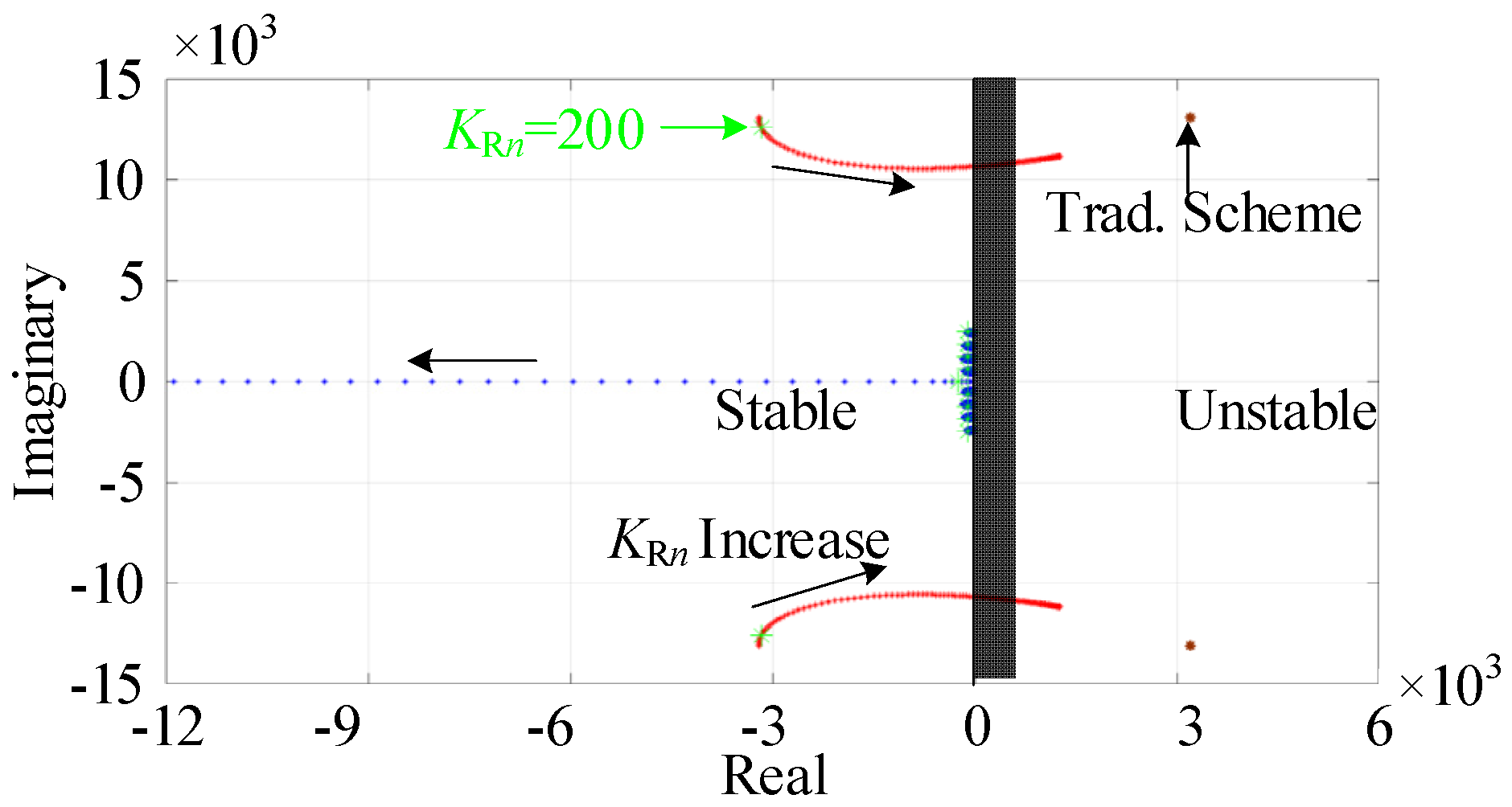
| Static Gain, KRn, of Each RC | 200 |
© 2019 by the authors. Licensee MDPI, Basel, Switzerland. This article is an open access article distributed under the terms and conditions of the Creative Commons Attribution (CC BY) license (http://creativecommons.org/licenses/by/4.0/).
Share and Cite
Lei, J.; Wei, C.; Feng, S. Input Disturbance Suppression for Unidirectional Matrix Converter with a Stability-Enhancing Modulation Scheme. Energies 2019, 12, 2625. https://doi.org/10.3390/en12132625
Lei J, Wei C, Feng S. Input Disturbance Suppression for Unidirectional Matrix Converter with a Stability-Enhancing Modulation Scheme. Energies. 2019; 12(13):2625. https://doi.org/10.3390/en12132625
Chicago/Turabian StyleLei, Jiaxing, Chaofan Wei, and Shuang Feng. 2019. "Input Disturbance Suppression for Unidirectional Matrix Converter with a Stability-Enhancing Modulation Scheme" Energies 12, no. 13: 2625. https://doi.org/10.3390/en12132625
APA StyleLei, J., Wei, C., & Feng, S. (2019). Input Disturbance Suppression for Unidirectional Matrix Converter with a Stability-Enhancing Modulation Scheme. Energies, 12(13), 2625. https://doi.org/10.3390/en12132625