Abstract
Vertical axis wind turbines (VAWTs) exhibit many advantages and great application prospect as compared with horizontal ones. However, large-scale VAWTs are rarely reported, and the codes and guidelines for designing large-scale VAWTs are lacking. Designing a large-scale composite blade requires precise finite element (FE) modeling and stress analysis at the lamina level, while precise modeling of an entire VAWT is computationally intensive. This study proposes a comprehensive fatigue and ultimate strength analysis framework for VAWTs. The framework includes load determination, finite element (FE) model establishment, and fatigue and ultimate strength analyses. Wind load determination has been presented in the companion paper. In this study, laminated shell elements are used to model blades, which are separately analyzed by ignoring the influence of the tower and arms. Meanwhile, beam elements are used to model an entire VAWT to conduct a structural analysis of other structural components. A straight-bladed VAWT in Yang Jiang, China, is used as a case study. The critical locations of fatigue and ultimate strength failure of the blade, shaft, arms, and tower are obtained.
1. Introduction
Vertical axis wind turbines (VAWTs) have received increasing interest in recent years [1,2,3,4,5,6]. Compared with horizontal axis wind turbines (HAWTs), VAWTs exhibit several advantages. For example, the generator and gearbox of a VAWT can be placed near the ground, which is convenient for maintenance and repair. VAWTs are insensitive to wind direction; therefore, the yaw system is not necessary, thereby greatly decreasing machine complexity [1]. In addition, VAWTs can operate well under high turbulent intensity conditions [2,3,4] and can be placed more compactly in a wind farm [5,6], although different conclusions have been reported [7,8]. Without cantilevered blades, the fatigue problem of VAWTs is less severe than HAWTs [1]. Hence, VAWTs have great potential on the large-scale wind turbine market. However, large-scale VAWTs are seldom studied and reported, and engineering experiences in the design and manufacturing of large-scale VAWTs are lacking. Therefore, the framework for the structural analysis of large-scale VAWTs is required.
Blades are one of the highly important components of VAWTs and account for approximately 20% of the total cost [9]. Wind turbine collapse due to blade failure has been reported in many references [10]. Fatigue and ultimate strength analyses are needed to improve the design of wind turbine blades. In addition, the critical locations of fatigue and ultimate strength failure need to be determined. Thus, a precise finite element (FE) model of the blade should be established. However, precise wind turbine modeling is computationally intensive. In a HAWT analysis, the blade is usually regarded as a cantilever, and the vibration of other components is neglected [11,12,13,14,15]. A similar approach can be applied to the blade of a VAWT.
For the analysis of other structural components, such as the tower, shaft, and hub, an ensemble model of the entire turbine is required because the influence of blades cannot be ignored. In contrast to composite blades, the tower, hub, and arms are usually made of steel or reinforced concrete, which can be modeled by beam elements. The FE method and multibody dynamics are usually used to simulate the rotation of HAWTS rotors [16,17,18,19]. A rotating frame method has been used to eliminate the rigid motion of VAWTs rotors, and centrifugal and Coriolis forces are added [20,21,22,23,24]. However, the tower response was not obtained. Hence, the tower response needs to be further studied when using this method, especially when tower strains are required.
In this study, a comprehensive structural analysis framework of VAWTs is proposed, using a real straight-bladed VAWT as an example. The VAWT developed by Hopewell Holdings Limited of Hong Kong is in Yang Jiang City, Guangdong Province, China. The tower of the VAWT is made of reinforced concrete with a height of 24 m and a diameter of 5 m. The thickness of the reinforced concrete wall of the tower is 250 mm. The tower supports a vertical rotor with a height of 26 m and a diameter of 40 m fitted with the rotating parts of the VAWT. The three blades of the rotor are equally arranged at an interval angle of 120°. The blades are of the NACA0018 type with a chord length of 2 m and a vertical height of 26 m. Each blade is made of glass fiber-reinforced plastic laminate materials and supported by a Y-type steel arm connected to the tower via the main shaft at the top of the tower (the hub height). Details can be found in the companion paper (Part I) [25].
The wind load simulation was proposed in the companion paper [25]. This study focuses on the fatigue and ultimate strength analyses. First, a precise 3D FE model of the laminated composite blade is established using laminated shell elements, and the numerical simulations under different load conditions are conducted. Stress and strain time histories in each ply of the blade are calculated, and fatigue and ultimate strength analyses of the laminated blade are performed. Second, an FE model of the entire VAWT is established using beam elements. The rotating frame method is used to analyze fatigue damage and the ultimate strength of all components of the VAWT except the blades and tower. The tower responses are obtained by a two-step method. The fatigue and ultimate strength analyses of the entire turbine (including the rotor and tower) under normal and extreme wind conditions, respectively, are conducted.
2. Analysis Framework
The structural analysis framework consists of two parts, as shown in Figure 1. The first part is to determine the design loads on all of the structural components of the VAWT, including the aerodynamic, inertial, and gravity forces. Wind loads can be obtained by the method proposed in the companion paper [25]. The second part is to establish the FE models and conduct the structural analysis of blades and other components. The proposed framework can provide information on fatigue and ultimate strength failure to facilitate the structural design of VAWTs. The lift-type straight-bladed VAWT introduced in the companion paper [25] is taken as an example.
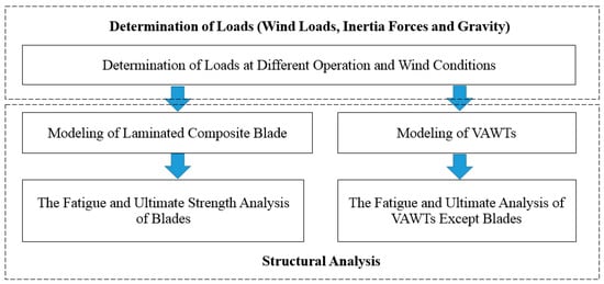
Figure 1.
Structural analysis framework of vertical axis wind turbines (VAWTs).
3. External and Operational Conditions in Analyses
In its service life, a wind turbine will be exposed to different operational and external conditions. The load cases and analysis type (i.e., fatigue or ultimate strength) are determined by the combination of the operational and external conditions.
The operational condition of a modern grid-connected wind turbine is divided into many types by IEC61400-1 [26] and Germanischer Lyoyd (GL) guideline [27]. The classification is for HAWTs, and some requirements of IEC61400-1 may be unsuitable to VAWTs. For example, the wind load is non-sensitive to wind direction for VAWTs. Hence, only the conditions of power production and standing still, which occupy a large proportion of the service life, are considered in this study in order to simplify the analysis. The influences of other conditions (i.e., startup, normal shut down, and idling) are ignored because the proportion of these conditions in the service life is small.
For external conditions, only the normal and extreme wind speeds are considered in this study. In the case of extreme wind speed, the ultimate strength analysis will be conducted while the fatigue analysis can be ignored as its possibility is very low. In the case of normal wind speeds ranging from 5 to 21 m/s, the blades are subjected to inertia and aerodynamic forces, thus fatigue damage will be calculated. As the wind speed is over 21 m/s, the VAWT is parked and the blades are subjected to the aerodynamic force only, which is not as significant as the combined force in the case of the normal wind speeds. For detailed load characteristics under operational and parking conditions, refer to the companion paper [25].
For the fatigue analysis, the annual mean wind speed distribution is required, which can be described by the Weibull model as in Equation (1)
where u is the mean wind speed and k and λ are the shape and scale parameters, respectively. For the VAWT under study, k = 2.0, λ = 8.1, the rotational speed of the blade is 2.1 rad/s (20 rpm), and the cut-in and cut-out wind speeds are 5 and 21 m/s, respectively. This mean wind speed region is divided into eight equal bins with an interval of 2 m/s. The centers of these bins are 6, 8, 10, 12, 14, 16, 18, and 20 m/s. The probability of the mean wind speed in one of wind speed bins can be calculated by Equation (1). The turbulence and wind profile are introduced in the companion paper [25]. Therefore, the fatigue damages experienced at the centers of wind speed bins in a short time can be extended to the total fatigue damage in 20 years. In the ultimate strength analysis, the extreme wind speed with a 50-year return period is considered. The wind speed, profile, and load simulation have been introduced in the companion paper [25]. Other loads (gravity and inertial forces) are introduced in the following sections.
4. Modeling and Structural Analysis of a Laminated Blade
4.1. FE Modeling of a Laminated Blade
The FE model of a blade is shown in Figure 2. This blade is of the NACA0018 foil type. The outer shell and shear webs of the blade are composed of three layers, as shown in Figure 2a. The first and third layers are made of plain weave fiber reinforced plastic (PW-FRP), and the middle one is made of unidirectional fiber reinforced plastic (UD-FRP). PW-FRP and UD-FRP are made of E-glass and polyester resin. E-glass is used as a fiber, and polyester resin is used as the matrix. The blade is manufactured by a pultrusion technique. These three layers are bonded together by latex.
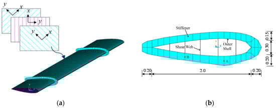
Figure 2.
Finite element (FE) model of the blade: (a) Top view; (b) Side view (unit: m).
Material coordinates are given in Figure 2a to define the elastic constants of UD-FRP and PW-FRP. From the view of macromechanics, UD-FRP is transversely isotropic, and PW-FRP is orthotropic. The elastic constants of UD-FRP can be represented by five independent constants (i.e., Ex, Ey, Gyx, Gyz, and νyx). Here “x” is the direction of the fibers, and “y” is in the plane and perpendicular to “x”. The elastic constants of PW-FRP can be represented by nine independent constants (i.e., Ex, Ey, Ez, Gyx, Gyz, Gzx, νyx, νyz, and νzx. Here, “x” and “y” are the directions of the warp and weft fibers; “z” is the direction normal to the xy-plane. The material properties of UD-FRP and PW-FRP are listed in Table 1.

Table 1.
Material properties of unidirectional fiber reinforced plastic (UD-FRP) and plain weave fiber reinforced plastic (PW-FRP).
The blade is modeled by element type Shell 91 in ANSYS [28] and shown in Figure 2a, and the side view of the blade model is illustrated in Figure 2b. Shell 91 exhibited eight nodes, each consisting of six degree-of-freedoms (DOFs) (i.e., translational displacement in X, Y, and Z and rotational along X, Y, and Z). Two identical steel brackets are used to fasten the blades near its two ends. The bracket is made of a steel stiffener and flange. The stiffener is welded to the middle of the flange by butt weld in a T shape. The stiffener and flange are 15 and 30 mm thick and 150 and 200 mm wide, respectively. The flange of the bracket was assumed to have a good contact with the blade. The flange and blade are simulated with one and three layers of shell elements, respectively. The connection between the stiffener and the flange is rigid. The blade is actually supported by the upper and lower arms through pin joints at A and B. Rayleigh damping is used in this study, and the damping ratio is 0.5%. The FE model consists of 7927 elements and 22,752 nodes, thereby resulting in 136,512 DOFs in total.
The blade rotates around the tower, thereby making the simulation challenging. A simplified approach is employed by attaching a rotating frame XYZ to the blade, which will be detailed in Section 5. The blade is regarded as a structure without any rigid motion as the frame and blade rotate around the tower together. Consequently, the inertial forces and simulated wind pressures are applied to the FE model. The responses of the blade can be obtained by solving the dynamic equation
where M, C, and K are the mass, Rayleigh damping, and stiffness matrices, respectively; u is the displacement vector composed of all displacements and rotations of all nodes in the rotating frame XYZ; is the velocity vector; is the acceleration vector; FW is the wind load; FG is the gravity; and FI is the initial force, including the centrifugal and Coriolis forces. Equation (2) is solved using the conventional average acceleration method offered by ANSYS (V16.2, ANSYS Inc., Pittsburgh, PA, USA). The strain can be extracted from the calculated displacement u.
4.2. Fatigue Analysis
The fatigue analysis of a laminated fiber reinforced plastic (FRP) blade is similar to that of a blade made of steel material. However, strain rather than stress time history is used to evaluate the fatigue damage [27,29]. The rain-flow counting method is applied to the strain time history, and the number of strain cycles in different strain range levels can be obtained. A cumulative damage model, such as the Palmgren–Miner’s rule, is used to evaluate the fatigue damage of the blade. The fatigue damage is defined as follows:
where ni is the cycle number of the equivalent zero-mean stress range εr,j in a given time period; Ni is the number of cycles to failure at the strain range εr,j; and D is defined as the fatigue damage. The composite is regarded as failed when D ≥ 1.
The number of cycles to failure at each strain range level can be estimated by the ε–N curve [27,29]. The Goodman diagram is required to equivalently convert the strain range with non-zero mean strain to that with a zero mean strain [27,29]. The diagram can be expressed by Equation (4).
where εt is the tensile ultimate strain, εc is the compressive ultimate strain, = (εmax + εmin)/2 is the mean strain, εr = εmax − εmin is the strain range, γ1 and γ2 are partial safety factors of the material and set to 2.64 and 1.96, respectively, according to the GL rules [27]. In this study, εt = 2.4%, εc = 2.4%, and m = 9. The strain in Equation (4) is the concerned laminar normal strain (either εx or εy), and the influence of the other strains is ignored. This simplified method is used in the present fatigue design of wind turbine blades [14,30,31]. Although the influence of multi-axial loading has been considered by some other researchers, the results are still limited [32,33].
Although the service life of a wind turbine is more than 20 years, conducting a numerical simulation over such a long period is unrealistic. An alternative method is adopted as follows: First, the operational mean wind speed range is discretized into several wind speed bins; second, the fatigue damage in a short term (e.g., 10 min) at the center of each bin is obtained by numerical simulation; finally, the proportion of these short term damages in the total fatigue damage for the designated time period is evaluated by the mean wind speed distribution. In this way, the final fatigue damage can be calculated. For this method, the mean wind speed distribution during the designated time period must first be available. As IEC 61400—1 [26] requires, the calculation of fatigue damage should be based on six 10-min or 1 h time history responses, which is computationally intensive and time consuming. In this study, only one 10-min time history of each bin was used to unveil the critical fatigue locations in this. This short time history simulation (10 min) can induce uncertainties when extrapolated to 20 years of damage [31,34]; these are not taken into account in the present analysis.
Furthermore, the fatigue-critical locations, which have large fatigue damage, should be determined for two reasons: (1) the fatigue life of a wind turbine blade is governed by these locations; and (2) it enables the improvement of blade design. The fatigue-critical locations can be determined by calculating the fatigue damage in 20 years. A total of six typical locations are selected as follows and as illustrated in Figure 3:
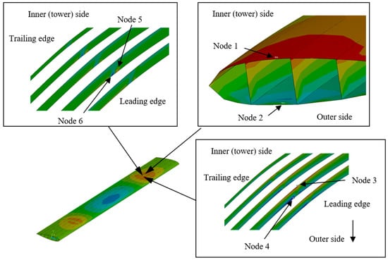
Figure 3.
Fatigue-critical sections.
- (1)
- The node of the largest εx range with positive mean at the lower support, which is located at the thickest portion of the blade section in the tower side, is defined as Node 1.
- (2)
- The node of the largest εx range with negative mean at the lower support, which is located at the thickest portion of the blade section in the outer side, is defined as Node 2. Nodes 1 and 2 are on the outer shell of the blade.
- (3)
- The node of the largest εx range with positive mean value in the shear web, which is at the lower support, is denoted as Node 3.
- (4)
- The node of the largest strain range with a negative mean value in the shear web, which is also at the shear web, is denoted as Node 4. Node 3 is adjacent to Node 1, and Node 4 is adjacent to Node 2.
- (5)
- For εy, the largest strain ranges with positive and negative mean values occur at the bond joint connecting the shear web to the outer shell of the blade at the lower support. Node 5 is defined as the node of the largest εy range with positive strain, which is at the bond joint connecting the shear web to the outer shell of the blade at the lower support.
- (6)
- The node of the largest negative strain range, which is also at the bond joint connecting the shear web to the outer shell of the blade at the lower support and near Node 5, is defined as Node 6.
By taking 14 m/s as an example, the strain time histories at Nodes 1–6 are shown in Figure 4, in which Nodes 1–4 and 5–6 are εx and εy, respectively.
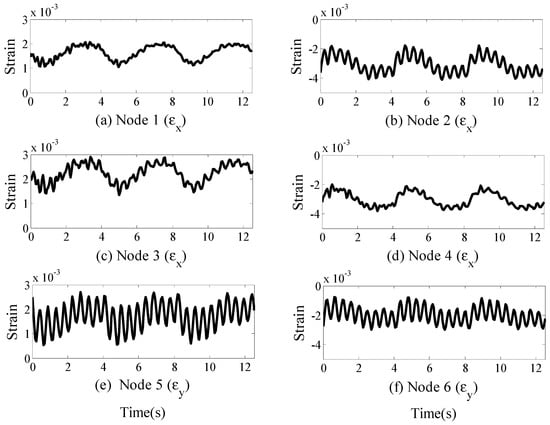
Figure 4.
Strain time histories of Nodes 1–6 (a–f).
For other wind speed bins, the strain time histories in 10 min are also calculated. The cycle numbers of different strain ranges and mean values of Nodes 1–6 are obtained by the rain-flow method. The numbers of cycles in 20 years were obtained by dividing them by 10 min and multiplying the time length of the mean wind speed within the corresponding wind speed bin, as shown in Figure 5. Strain cycles can be categorized into two groups: one with a scattering mean strain and narrow strain ranges and the other with a centralized mean strain and wide strain ranges. In addition, the strain ranges of Nodes 2, 5, and 6 are larger than the other three nodes.
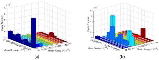
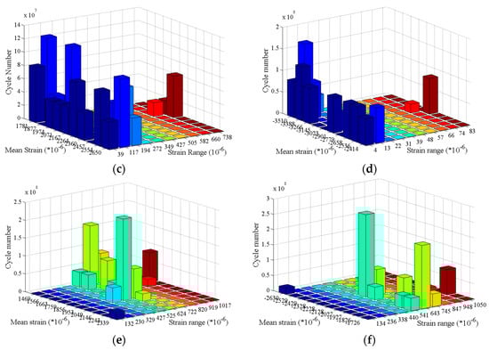
Figure 5.
Rain-flow counting matrix plot: (a) Node 1; (b) Node 2; (c) Node 3; (d) Node 4; (e) Node 5; (f) Node 6.
The fatigue damage of these nodes is calculated by Equations (3) and (4). Meanwhile, the fatigue damage of different mean strains and strain ranges is shown in Figure 6, and the total fatigue damage of these six nodes in 20 years is listed in Table 2. A comparison of Figure 5 and Figure 6 shows that the fatigue damage of the large strain ranges is dominant even though the cycle number of small strain ranges is much larger than that of the large ones. Table 2 shows that the fatigue life of this blade is controlled by the compressive fatigue damage at Node 2. This phenomenon is different from metals, for which the fatigue problem in the compressive stress is obscured. Previous studies have found that the reduction in the resistance to the fatigue of FRP at the compressive strain state is due to micro-buckling, fiber crushing, splitting of the matrix, buckling delamination of a surface layer, and shear band formation [35,36]. Although the fatigue damage of Node 2 is only 0.1020, conclusions cannot safely be drawn because the fatigue mechanism of composite materials is complicated, and the uncertainty of the fatigue design of composite materials is high. Although the cycles with small strain ranges cause negligible fatigue damage, they have an influence on determining the largest strain range.
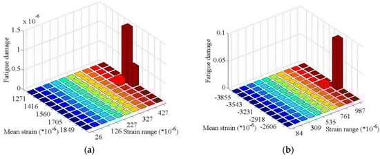
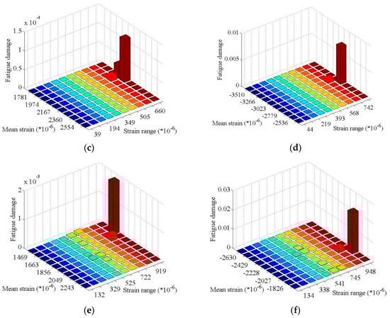
Figure 6.
Matrix plot of fatigue damage of different mean strains and strain ranges: (a) Node 1; (b) Node 2; (c) Node 3; (d) Node 4; (e) Node 5; (f) Node 6.
Table 2.
Fatigue damage of Nodes 1–6 in 20 years.
4.3. Ultimate Strength Analysis
Under the extreme wind speed condition, the VAWT is parked, and only wind pressures are applied on the blade. The design wind speed is defined in the companion paper [25] in accordance with the suggestions of IEC61400-1. The influence of turbulence is considered in the equivalent static wind load. The extreme wind loads at different azimuth angles are applied on the blade to study the influence of wind direction. Then, the adverse azimuth angle and failure-critical locations of the blade are obtained.
The Tsai–Wu strength index [37] is used to evaluate the failure-critical locations as follows
where P is the strength index; F1 = 1/T1 − 1/C1; F2 = 1/T2 − 1/C2; F12 = −1/; F11 = 1/(T1C1); F22 = 1/(T2C2); ; σi (i = 1, 2, 3) is the normal stress in three directions of anisotropy; τ12 is the in plane shear stress; and “T”, “C”, and “S” represent the ultimate tensile, compressive, and shear stress, respectively. The Tsai–Wu criterion is applied to the failure analysis of each lamina of the laminated blade. The blade is regarded as failed when the failure index is equal to or larger than one. The larger the index, the more likely a failure is to occur.
As described earlier, the blade is made of a three-layer laminated FRP: the first and third layers are PW-FRP, and the second one is UD-FRP. The ultimate strength of the composite material is from the Department of Energy/Montana State University (DOE/MSU) database [38]. Specifically, the T1, C1, T2, C2, and S12 of the UD-FRP are selected as 773, −653, 26, −123, and 106 MPa, respectively, where “1” is the fiber direction of the UD-FRP. The T1, C1, T2, C2, and S12 of the PW-FRP are set as 380, −240, 380, 240, and 97 MPa, where “1” and “2” are the directions of the warp and weft, respectively.
The blade responses at different azimuth angles are obtained. Here, the azimuth angles considered are 0°, 30°, 60°, 90°, 120°, 150°, 180°, 210°, 240°, 270°, 300°, and 330°. At each azimuth angle, the stresses in each lamina of the blade can be obtained, and the P value is calculated as in Equation (15). The results show that the failure critical locations (with large P values) for different azimuth angles are the same and are located at the supports and the mid-span of the blades. The largest Tsai–Wu strength index appears at the upper support of the blade. By taking 90° as an example, the Tsai–Wu strength indices P in the three laminas are shown in Figure 7, in which the largest index in each lamina (Pmax) is given.
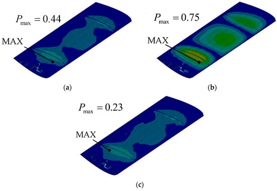
Figure 7.
Tsai–Wu strength index P: (a) First lamina (Pmax = 0.44); (b) Second lamina (Pmax = 0.75); (c) Third lamina (Pmax = 0.23).
The graph of Pmax versus azimuth angle is shown in Figure 8. Pmax in the second lamina is generally larger than those in the first and third laminae. Pmax exhibited two peaks: one is in the upwind side (in the range between 60° and 90°), and the other is in the backwind side (near 240°). The former is highly unfavorable.
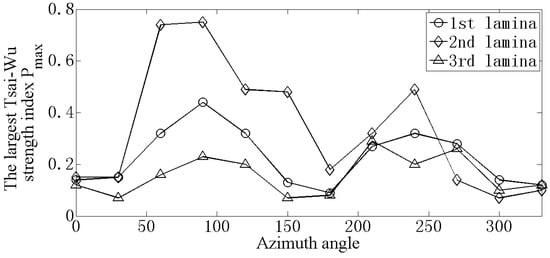
Figure 8.
Largest strength index for different azimuth angles.
5. Modeling and Structural Analysis of the Entire VAWT
5.1. FE Modeling of a Straight-Bladed VAWT
The global FE model of the VAWT is shown in Figure 9a. The tower and hub are modeled by 26 and eight beam elements, respectively; the shaft by 20 elements; each main, upper, and lower arm by 20, 28, and 28 elements, respectively; and each link and blade by 27 and 50 elements, respectively. The FE model of the VAWT consists of 519 elements, 673 nodes, and 4020 DOFs in total. The connections between different components are shown in Figure 9b. The hub is connected to the top of the tower by a rigid joint. The shaft is connected to the hub by two hinge joints (i.e., one at the top of the hub and the other at the bottom). The main arms link the top of the shaft and the upper and lower arms by rigid joints. The links and blades are connected to the upper and lower arms by hinge joints. The material properties of the components are listed in Table 3.
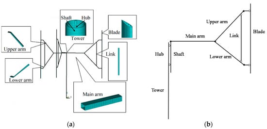
Figure 9.
FE model of a straight-bladed VAWT: (a) FE model; (b) Connections.
Table 3.
Material properties of the components of the FE model.
Modern large wind turbines are all grid-connected and generally operated at a specific rotational speed. The rotational mode of the rotor will differ slightly depending on the generator type: a synchronous generator is precisely operated at a given rotational speed and an asynchronous generator at varying wind speeds but is subject to a maximum of 5% variation. If the rotational speed of the rotor is assumed to be constant, the rotating frame method can be used to analyze the structural responses of a VAWT [20,21,22,23,24]. The rotating frame rotates at the same speed as the rotor. Therefore the rigid motion of the VAWT can be eliminated, and only the inertial forces and wind loads need to be considered.
The rotating frame XYZ is established as shown in Figure 10. The origin is set at the bottom of the tower, the Z-axis is along the VAWT tower, and the other two axes (X and Y) are normal to the tower. The frame rotates with the rotor of the VAWT at the same rotational speed along the Z-axis. The reference frame XoYoZo and the origin are fixed at the bottom of the tower. At the azimuth angle of 0°, these two frames coincide with each other (Figure 10a). When the rotor rotates to an azimuth angle of θ, the frame XYZ also rotates around the tower by θ (Figure 10b).
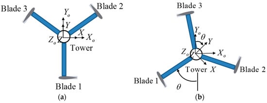
Figure 10.
Rotating and reference frames: (a) At the azimuth of 0°; (b) At the azimuth of θ.
In the frame XYZ, the VAWT can be regarded as a structure without any rigid body displacement, and only non-inertial forces can act on the rotor. The dynamic equation of the rotor and tower in XYZ can be rewritten as follows:
where FE and FC are the carrier inertial (centrifugal) and Coriolis forces on the rotor.
In the actual situation (in XoYoZo), the rotor is rotating, and the tower is stationary. However, in XYZ, the rotor is static, and the tower rotates around the Z-axis in the opposite direction. The bending stiffness would remain constant during rotation due to the axial symmetry of the tower. Therefore the interaction between the rotor and the tower would not be influenced by disregarding the rotation of the tower in XYZ. However, the tower response cannot be directly obtained from Equation (6) because a static point of the tower in XYZ is actually rotating in XoYoZo. In this regard, a two-step method is proposed here to obtain the tower responses. First, the rotor responses are obtained by solving Equation (6). Then, the tower is independently calculated in the frame XoYoZo. The interaction forces by the rotor can be calculated from Equation (6). The dynamic equation of the tower in XoYoZo can be written as follows:
where the subscript T represents the items related to the tower and hub, FRo is the reaction force from the shaft described in XoYoZo, FWo is the wind load on the tower described in XoYoZo, and FGT is the gravity force of the tower.
5.2. Fatigue Analysis
In this section, the VAWT responses in the operational wind speed range are simulated, and the fatigue analysis is conducted. This section focuses on the shaft, the main, upper, and lower arms, and the tower, because the blade has been analyzed in Section 4.
The S–N curve for steel is determined by the GL rule, as shown below:
where ND = 5 × 10⁶; ΔσD is the stress range corresponding to ND in the case of R = σmax/σmin = −1 (σmax and σmin are the maximum and minimum stresses, respectively, similar to a stress cycle); and Δσ is the stress range corresponding to the case of a zero-mean. For the mean stress = (σmax + σmin)/2, the equivalent stress range can be obtained by the Goodman diagram as follows:
where σs is the ultimate tensile strength.
For concrete, the S–N curve for the compressive load is given by DIN 1045-1 and EN 1992-1-1 [39,40] as
where Smax = σck,max/fck,fat and Smin = σck,min/fck,fat; σck,max and σck,min are the magnitudes of the maximum and minimum concrete compression stress, fck,fat = 0.85fck(1−fck/250), and fck is the characteristic compressive strength. In this study, C40 concrete is used, and fck = 26.8 MPa.
The fatigue-critical locations are the positions that suffer from the largest fatigue damage during the service life. Three critical sections (i.e., A, B, and C) of the main arm and shaft are selected, as shown in Figure 11. Sections A and B are located at the two ends of the main arm. The former is at the root of the main arm, and the latter is at the connection between the main and the upper and lower arms. Section C is on the shaft, at the height of the main arms. In Sections A and B, the normal stresses due to vertical (σx,vA and σx,vB) and horizontal (σx,hA and σx,hB) bending are extracted at points A1, B1, A2, and B2 (Figure 11b). The normal stresses due to the bending of the shaft in Section C (σx,C1 and σx,C2) are also obtained at points C1 and C2, as shown in Figure 11c. Here, the subscript x means that the stress direction is normal to the cross-section.
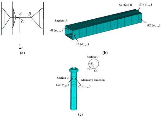
Figure 11.
Fatigue-critical locations of the VAWT: (a) Critical sections; (b) Critical locations on the main arm; (c) Critical locations on the shaft.
The stress time histories at the fatigue-critical locations at the mean wind speeds of the center of each bin (6, 8, 10, 12, 14, 16, 18, and 20 m/s) are calculated. The result of σx,vA is shown in Figure 12. The amplitude of σx,vA increases as the wind speed increases. When the 10-min stress time histories at A1, A2, B1, B2, C1, and C2 under different mean wind speeds are obtained, the cycle numbers for different stress ranges and mean values are acquired by the rain-flow method. Then, these cycle numbers during the 10-min time history are extended to the numbers in 20 years by the wind speed distribution function. The fatigue damage during 20 years at these six points are calculated and listed in Table 4. Two large fatigue damages occur in Section A, one being caused by the vertical bending normal stress and the other by the horizontal one. The shaft exhibited minimal damage. Therefore, the fatigue life of the typical VAWT considered in this study is dominated by fatigue damage at the root of the main arms. Although the fatigue damage of the shaft is small, fatigue in this location should not be ignored because misalignment of the rotor and eccentric mass are not considered in this study.
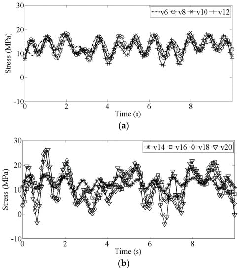
Figure 12.
Time histories of σx,vA at different mean wind speeds: (a) Mean wind speed of 6–12 m/s; (b) Mean wind speed of 14–20 m/s.
Table 4.
Fatigue damage at the fatigue-critical locations in 20 years.
The forces on the tower consist of the gravity force, wind load, and reaction forces from the shaft. The gravity force is the uniform volume force; the wind load is horizontal and distributed along the tower; and the forces from the shaft provided by the rotor are acted at the top of the tower. Under these forces, the bottom of the tower is the fatigue-critical location subjected to the largest stress and stress range. Therefore, the cyclic stress at the bottom of the tower is considered.
Section D at the bottom of tower is selected, as shown in Figure 13a. Two typical points under compressive stresses, D1 and D2 (Figure 13b), are selected in this section and the stresses (σZo,D1 and σZo,D2) at D1 and D2 are extracted. Although the windward point (opposite D1 in Figure 13b) has the same fluctuating stress amplitude as D1, its mean stress is smaller than D1 because the tensile stress is cancelled out by the self weight of the structure. Consequently, the windward point is not selected for the fatigue analysis. The stresses σZo,D1 and σZo,D2 are calculated in XoYoZo along the Zo direction. The simulated stress time histories of σZo,D1 and σZo,D2 at the mean wind speed of 14 m/s are shown in Figure 14. The mean of σZo,D1 is larger than that of σZo,D2 because D1 is at the leeward side of the tower. Thus, the bending moment caused by the mean wind induces an extra stress component at point D1.
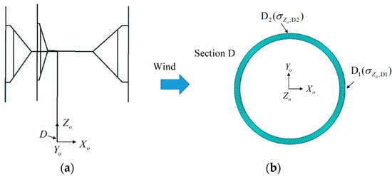
Figure 13.
Fatigue-critical points of the tower: (a) Position of Section D; (b) Critical points in Section D.
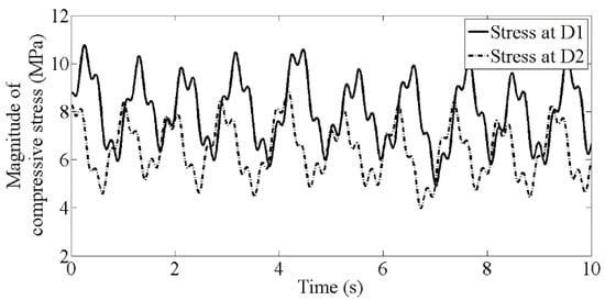
Figure 14.
Vertical stresses at D1 and D2 at a mean wind speed of 14 m/s.
The fatigue damages at D1 and D2 over 20 years obtained using Miner’s rule and the S–N curve of concrete given by Equation (10) are 0.1017 and 0.0029, respectively. D1 suffered larger fatigue damage than D2 due to its larger compressive stress. Although the stress ranges are the same, a large mean stress would decrease the cycle number to failure, thereby increasing the fatigue damage.
5.3. Ultimate Strength Analysis
Wind turbines are parked under extreme wind speed conditions. As explained earlier, only the ultimate strength analysis is conducted under the aforementioned condition. The failure-critical locations are determined according to von Mises stress.
The wind direction influences the wind load and the magnitude of the von Mises stress as the VAWT is parked. Therefore, four azimuth angles (i.e., 0°, 30°, 60°, and 90°) are considered. Notably, for the entire VAWT, the 120° azimuth angle coincides with 0°.
The blades have been analyzed in Section 4. Only the arms and shaft are studied in this section. The fatigue-critical locations, that is, A1, A2, B1, B2, C1, C2, D1, and D2 (Figure 11 and Figure 13), have large von Mises stresses, which are shown in Figure 15 with respect to different azimuth angles. For the main arm (Sections A and B), a large stress occurs at the azimuth angle of 60° and 240° (in the front and back wind side, respectively). σv,vA at A1 and σv,vB at B1, caused by vertical bending, are larger than σv,hA at A2 and σv,hB at B2, caused by horizontal bending. For the shaft, σv,C1 and σv,C2 exhibit three peaks in a cycle due to the three-blade structure, and the peaks occur at the 30°, 150°, and 270° azimuth angles. The von Mises stresses of the tower (σv,D1 and σv,D2) also demonstrate three peaks in a cycle. The peaks of σv,D1 and σv,D2 occur at 60°, 180°, and 300° and 30°, 150°, and 270°, respectively. σv,D2 is much smaller than σv,D1 due to the influence of the mean wind direction. Hence, the critical failure location of the tower is dominated by σv,D1. In summary, the unfavorable azimuth angles under extreme wind speed conditions are 60° and 240° for the main arms, 30°, 150°, and 270° for the shaft, and 60°, 180°, and 300° for the tower.
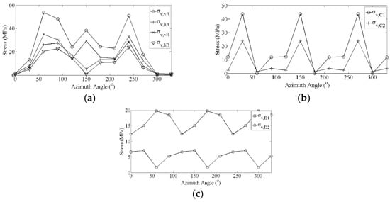
Figure 15.
Von Mises stresses at fatigue-critical locations: (a) At A1, A2, B1, and B2; (b) At C1 and C2; (c) At D1 and D2.
6. Conclusions
In this study, a structural analysis framework of VAWTs has been proposed. The framework includes the determination of loads and structural analyses of different components of VAWTs. First, the loads under different operation and wind speed conditions were determined. The important wind load was simulated in the companion paper [25]. Then, the FE models of the laminated composite blade and the entire VAWT were established. Finally, fatigue and ultimate strength analyses of the blade and other components were conducted. The following conclusions can be drawn:
- (1)
- The fatigue-critical locations of the blades under power production and normal turbulent wind conditions were determined. Locations at the supports and the mid-span of the blade exhibited larger fatigue damage than other positions. The largest fatigue damage occurred at the cross-section of the lower support, where compressive loads demonstrated larger fatigue damage than tensile cyclic loads.
- (2)
- The ultimate strength analysis of the blade under extreme wind speed conditions was also considered. In this case, the wind turbine was parked. The influence of the wind direction on the responses of the blade was studied. The highly unfavorable azimuth angle is in the upwind side, which is in the range between 60° and 90°. The failure-critical location is in the cross-section of the upper support. The locations with large inter-laminar stresses, besides the critical-failure ones predicted by the Tsai–Wu criteria, were also determined.
- (3)
- The fatigue analysis was conducted on the basis of the FE model and rotating frame method. The largest fatigue damage occurred at the root of the main arms. Although the fatigue damage of the shaft was small for this typical VAWT, it cannot be ignored, because the misalignment of the rotor and eccentric mass were not considered here. The fatigue-critical location of the tower was at the bottom, and the fatigue damage of the tower was calculated. Significant fatigue damage occurred at the leeward side of the tower.
- (4)
- An ultimate strength analysis of the rotor and tower was conducted. The von Mises stresses of the rotor and tower were calculated. The largest stress on the components occurred at the fatigue-critical locations.
Author Contributions
Conceptualization, Y.-l.X.; Methodology, Y.-l.X. and J.L.; Software, J.L.; Validation, J.L. and Y.X.; Formal analysis, J.L.; Investigation, J.L.; Resources, Y.-l.X.; Data curation, J.L.; Writing—original draft preparation, J.L. and Y.-l.X.; Writing—review and editing, Y.X.; Visualization, J.L. and Y.X.; Supervision, Y.-l.X.; Project administration, Y.-l.X.; Funding acquisition, Y.-l.X.
Funding
This research was funded by the CII-HK/PolyU Research Fund, grant number 5-ZJE7.
Acknowledgments
The authors are grateful to G.Y.S.W. and L.K.K.L. from Hopewell Holdings Limited of Hong Kong for allowing us to use their innovative vertical axis wind turbine as a case study.
Conflicts of Interest
The authors declare no conflict of interest. The funder had no role in the design of the study, in the collection, analyses, or interpretation of data, in the writing of the manuscript, or in the decision to publish the results.
References
- Ashwill, T.D.; Sutherland, H.J.; Berg, D.E. A Retrospective of VAWT Technology; Technical Reports; Sandia National Laboratories: Albuquerque, NM, USA, 2012. [Google Scholar]
- Kooiman, S.J.; Tullis, S.W. Response of a Vertical Axis Wind Turbine to Time Varying Wind Conditions found within the Urban Environment. Wind. Eng. 2010, 34, 389–402. [Google Scholar] [CrossRef]
- Peng, H.; Lam, H. Turbulence effects on the wake characteristics and aerodynamic performance of a straight-bladed vertical axis wind turbine by wind tunnel tests and large eddy simulations. Energy 2016, 109, 557–568. [Google Scholar] [CrossRef]
- Ahmadi-Baloutaki, M.; Carriveau, R.; Ting, D.S.-K. Performance of a vertical axis wind turbine in grid generated turbulence. Sustain. Technol. Assess. 2015, 11, 178–185. [Google Scholar] [CrossRef]
- Dabiri, J.O. Potential order-of-magnitude enhancement of wind farm power density via counter-rotating vertical-axis wind turbine arrays. J. Renew. Sustain. Energy 2011, 3, 43104. [Google Scholar] [CrossRef]
- Ryan, K.J.; Coletti, F.; Elkins, C.J.; Dabiri, J.O.; Eaton, J.K. Three-dimensional flow field around and downstream of a subscale model rotating vertical axis wind turbine. Exp. Fluids 2016, 57, 38. [Google Scholar] [CrossRef]
- Albers, A. Turbulence and shear normalization of wind turbine power curve. In Proceedings of the EWEC 2010, Warsaw, Poland, 20–23 April 2010; Volume 6, pp. 4116–4123. [Google Scholar]
- Pagnini, L.C.; Burlando, M.; Repetto, M.P. Experimental power curve of small-size wind turbines in turbulent urban environment. Appl. Energy 2015, 154, 112–121. [Google Scholar] [CrossRef]
- International Renewable Energy Agency. Wind Power, Renewable Energy Technologies: Cost Analysis Series; International Renewable Energy Agency: Abu Dhabi, United Arab Emirates, 2012; Volume 1, Power Sector, Issue 5. [Google Scholar]
- Gipe, P. Wind Energy—The Breath of Life or the Kiss of Death: Contemporary Wind Mortality Rates. Available online: http://www.wind-works.org/articles/BreathLife.html (accessed on 10 February 2005).
- Castelli, M.R.; Monte, A.D.; Quaresimin, M.; Benini, E. Numerical evaluation of aerodynamic and inertial contributions to Darrieus wind turbine blade deformation. Renew. Energy 2013, 51, 101–112. [Google Scholar] [CrossRef]
- Jensen, F.; Falzon, B.; Ankersen, J.; Stang, H.; Falzon, B. Structural testing and numerical simulation of a 34m composite wind turbine blade. Compos. Struct. 2006, 76, 52–61. [Google Scholar] [CrossRef]
- Jung, S.N.; Dhadwal, M.K.; Kim, Y.W.; Kim, J.H.; Riemenschneider, J. Cross-sectional constants of composite blades using computed tomography technique and finite element analysis. Compos. Struct. 2015, 129, 132–142. [Google Scholar] [CrossRef]
- Peeters, M.; Santo, G.; Degroote, J.; Van Paepegem, W. Comparison of Shell and Solid Finite Element Models for the Static Certification Tests of a 43 m Wind Turbine Blade. Energies 2018, 11, 1346. [Google Scholar] [CrossRef]
- Song, S.H.; Kang, S.I.; Hahm, N.K. Optimization design, modeling and dynamic analysis for composite wind turbine blade. Procedia Eng. 2011, 16, 369–375. [Google Scholar] [CrossRef]
- Kang, N.; Park, S.C.; Park, J.; Atluri, S.N. Dynamics of flexible tower-blade and rigid nacelle system: Dynamic instability due to their interactions in wind turbine. J. Vib. Control 2016, 22, 826–836. [Google Scholar] [CrossRef]
- Kessentini, S.; Choura, S.; Najar, F.; Franchek, M. Modeling and Dynamics of a Horizontal Axis Wind Turbine. J. Vib. Control 2010, 16, 2001–2021. [Google Scholar] [CrossRef]
- Luo, T.; Tian, D.; Wang, R.Y.; Liao, C.C. Stochastic Dynamic Response Analysis of a 10 MW Tension Leg Platform Floating Horizontal Axis Wind Turbine. Energies 2018, 11, 3341. [Google Scholar] [CrossRef]
- Saravia, C.M.; Machado, S.P.; Cortínez, V.H. A composite beam finite element for multibody dynamics: Application to large wind turbine modeling. Eng. Struct. 2013, 56, 1164–1176. [Google Scholar] [CrossRef]
- Berg, D.E. Structural Design of the Sandia 34-m Vertical-Axis Wind Turbine; Nasa Sti/recon Technical Report N,85; Sandia National Laboratories: Albuquerque, NM, USA, 1985. [Google Scholar]
- Lobitz, D.W.; Ashwill, T. Aeroelastic Effects in the Structural Dynamic Analysis of Vertical Axis Wind Turbines; Sandia National Labs.: Albuquerque, NM, USA, 1986. [Google Scholar]
- Popelka, D. Aeroelastic Stability Analysis of a Darrieus Wind Turbine; Sandia National Laboratories: Albuquerque, NM, USA, 1982. [Google Scholar]
- Carne, T.; Lobitz, D.; Nord, A.; Watson, R. Finite element analysis and modal testing of a rotating wind turbine. In Proceedings of the 23rd Structures, Structural Dynamics and Materials Conference, New Orleans, LA, USA, 10–12 May 1982. [Google Scholar]
- Thresher, R.W.; Mirandy, L.P.; Carne, T.G.; Lobitz, D.W.; James, G.H. Structural Dynamic Behavior of Wind Turbines Wind Turbine Technology: Fundamental Concepts in Wind Turbine Engineering, 2nd ed.; ASME Press: Fairfield, NJ, USA, 2009. [Google Scholar]
- Lin, J.H.; Xu, Y.L.; Xia, Y.; Li, C. Structural Analysis of Large-Scale Vertical-Axis Wind Turbines I: Wind Load Simulation. Energies 2019. submitted for publication. [Google Scholar]
- International Electrotechnical Commission. IEC 61400-1: Wind Turbines Part 1: Design Requirements. Ed 3.; IEC: Geneva, Switzerland, 2015. [Google Scholar]
- Germanischer, Lloyd. Guideline for the Certification of Wind Turbines; Germanischer Lloyd Industrial Services GmbH: Hamburg, Germany, 2010. [Google Scholar]
- ANSYS Inc. Programmer’s Manual for ANSYS; ANSYS Inc.: Pittsburgh, PA, USA, 2007. [Google Scholar]
- Burton, T.; Jenkins, N.; Sharpe, D.; Bossanyi, E. Wind Energy Handbook; John Wiley & Sons: Somerset, NJ, USA, 2001. [Google Scholar]
- Kong, C.; Bang, J.; Sugiyama, Y. Structural investigation of composite wind turbine blade considering various load cases and fatigue life. Energy 2005, 30, 2101–2114. [Google Scholar] [CrossRef]
- Sutherland, H.J. On the Fatigue Analysis of Wind Turbines; Sandia National Laboratories: Albuquerque, NM, USA, 1999. [Google Scholar]
- Quaresimin, M. 50th Anniversary Article: Multiaxial Fatigue Testing of Composites: From the Pioneers to Future Directions. Strain 2015, 51, 16–29. [Google Scholar] [CrossRef]
- Quaresimin, M.; Susmel, L.; Talreja, R. Fatigue behaviour and life assessment of composite laminates under multiaxial loadings. Int. J. Fatigue 2010, 32, 2–16. [Google Scholar] [CrossRef]
- Repetto, M.P.; Torrielli, A. Long term simulation of wind-induced fatigue loadings. Eng. Struct. 2017, 132, 551–561. [Google Scholar] [CrossRef]
- Brøndsted, P.; Lilholt, H.; Lystrup, A. COMPOSITE MATERIALS FOR WIND POWER TURBINE BLADES. Annu. Rev. Mater. Res. 2005, 35, 505–538. [Google Scholar] [CrossRef]
- Budiansky, B.; Fleck, N. Compressive failure of fibre composites. J. Mech. Phys. Solids 1993, 41, 183–211. [Google Scholar] [CrossRef]
- Tsai, S.W.; Wu, E.M. A General Theory of Strength for Anisotropic Materials. J. Compos. Mater. 1971, 5, 58–80. [Google Scholar] [CrossRef]
- Mandell, J.F.; Samborsky, D.D. DOE/MSU Composite Material Fatigue Database. Version, 18; Montana State University: Bozeman, MT, USA, 2009. [Google Scholar]
- De Normalisation, C.E. Eurocode 2: Design of Concrete Structures: Part 1: General Rules and Rules for Buildings; European Committee for Standardization: Brussels, Belgium, 1991. [Google Scholar]
- German Institute for Standardization. DIN 1045-1; German Institute for Standardization: Berlin, Germany, 2003. [Google Scholar]


© 2019 by the authors. Licensee MDPI, Basel, Switzerland. This article is an open access article distributed under the terms and conditions of the Creative Commons Attribution (CC BY) license (http://creativecommons.org/licenses/by/4.0/).