Article

An Investigation of the Influence of Gas Injection Rate Shape on High-Pressure Direct-Injection Natural Gas Marine Engines

1
State Key Laboratory of Engines, Tianjin University, Tianjin 300072, China
2
China Ship Power Research Institute Co., Ltd., Shanghai 200120, China
*
Author to whom correspondence should be addressed.
Energies 2019, 12(13), 2571; https://doi.org/10.3390/en12132571
Submission received: 10 May 2019 / Revised: 22 June 2019 / Accepted: 1 July 2019 / Published: 4 July 2019

Abstract

:
High-pressure direct-injection (HPDI) natural gas marine engines are widely used because of their higher thermal efficiency and lower emissions. The effects of different injection rate shapes on the combustion and emission characteristics were studied to explore the appropriate gas injection rate shapes for a low-speed HPDI natural gas marine engine. A single-cylinder model was established and the CFD model was validated against experimental data from the literature; then, the combustion and emission characteristics of five different injection rate shapes were analyzed. The results showed that the peak values of in-cylinder pressure and heat release rate profiles of the triangle shape were highest due to the highest maximum injection rate, which occurred in a phase close to the top dead center. The shorter combustion duration of the triangle shape led to higher indicated mean effective pressure (IMEP) and NOx emissions compared with other shapes. The higher initial injection rates of the rectangle and slope shapes had a negative effect on the ignition delay periods of pilot fuel, which resulted in lower in-cylinder temperature and NOx emissions. However, due to the lower in-cylinder temperature, the engine power output was also lower. Otherwise, soot, unburned hydrocarbon (UHC), and CO emissions and indicated specific fuel consumption (ISFC) increased for both rectangle and slope shapes. The trapezoid and wedge shapes achieved a good balance between fuel consumption and emissions.

1. Introduction

In recent years, oil shortages and environmental pollution have generated interest in reducing emissions from marine engines and clean, new alternative energies. The combustion of heavy oil produces CO2 emissions, which is directly associated with combustion efficiency. Further, the reduction of emissions is also associated with combustion efficiency and fuel consumption. The common emissions of marine engines are CO2, hydrocarbon (HC), CO, sulfur, NOx, and soot. CO2 is a greenhouse gas and is directly associated with engine fuel consumption, while the other emissions are harmful to the environment. Increasingly restrictive regulations have limited the emissions of marine engines [1]. Sulfur emissions have been controlled by the International Maritime Organization (IMO) since 2005 and are therefore no longer an issue for marine engines when low-sulfur fuel is used [2]. However, the NOx–soot trade-off makes it difficult to simultaneously reduce NOx and soot emissions in conventional diesel engines fueled with heavy oil [3]. Since it is very difficult to simultaneously make NOx and soot emissions meet emission regulations by only improving the combustion process, other abatement technology must be applied.
To reduce NOx emissions, technical solutions such as selective catalytic reduction (SCR), dual-fuel (DF)/gas engines, exhaust gas recirculation (EGR), and so forth have been applied [4]. These technologies have their advantages and disadvantages. Considering the current main study and application state, SCR, EGR, and dual-fuel engines are appropriate technologies to be used in the near future [5,6,7,8]. The employment of an SCR system can satisfy regulations for NOx emissions. However, the high cost of the SCR system is an issue that needs to be addressed and operational problems of the SCR system arise when the exhaust temperature is low [9,10]. NOx emissions can be reduced below regulation limits when high an EGR rate is applied [11,12], but soot emissions increase rapidly and the thermal efficiency decreases sharply. Therefore, the application of EGR cannot be used as a separate technical solution to reduce emissions. As a gas engine operating with a low carbon/hydrogen ratio, a natural gas engine is also a technical solution due to the cleaner combustion characteristics and plentiful reserves of natural gas. In addition, the high-octane value and antiknock properties permit a high compress ratio, therefore achieving high thermal efficiency [13,14]. Moreover and more importantly, nowadays, natural gas can be produced from various biomass feedstocks [15,16], thus increasing its eco-friendly merits, with this gas called bio-methane, bio-compressed natural gas (CNG), or “green gas”. Previous studies showed that natural gas engines could reduce NOx emissions by approximately 50–80% while producing almost zero soot emissions [17]. CO2 emissions are also relatively low compared with traditional gasoline or diesel engines due to the lower carbon/hydrogen ratio of natural gas. Therefore, natural gas engines have the potential to be widely applied all over the world in future.
With the development of natural gas engines, their utilization has also been extended to heavy-duty and marine engines, where good power performance is in great demand [18,19,20,21,22]. Nowadays, there are primarily three kinds of operating modes for natural gas engines. The first mode is a pure natural gas engine, and the natural gas is ignited by a spark plug. In the second mode, the engine operates with premixed natural gas and direct-injection pilot diesel, where the natural gas is introduced into intake air during the intake stroke (low-pressure dual-fuel engines). In this type of engine, a homogenous natural gas/air mixture is compressed rapidly below its autoignition condition and it is ignited by the injection of an amount of pilot diesel near top dead center. The engine load is only controlled by changing the amount of natural gas. At a medium or high load, the emissions of low-pressure dual-fuel engines are relatively low. However, at a light load, unburned HC (UHC) emissions sharply increase. In addition, due to the limitation of engine knocking, the engine power and efficiency are also challenges of low-pressure dual-fuel engines. In the third mode, natural gas and pilot diesel are both directly injected into the cylinder near top dead center, and these are generally called high-pressure direct-injection (HPDI) dual-fuel engines. In this type of engine, pilot diesel is injected into the cylinder prior to high-pressure natural gas [14]. When the natural gas is injected into the cylinder, the diesel is spontaneously ignited. The natural gas is entrained into the pilot flame and ignited. Due to the slower flame propagation speed of natural gas, pure natural gas engines are suitable for small-scale engines, while dual-fuel engines are usually used for heavy duty and marine engines [2]. Recently, the natural gas dual-fuel marine engine has been widely studied [23,24,25,26,27,28], and typical studies have been done by engine companies such as MAN B&W and Wärtsilä. The advantage of HPDI natural gas engines is the higher thermal efficiency and engine power due to their mixed controlled combustion rate as well as antiknock characteristics. However, the challenge is the higher NOx and soot emissions compared with low-pressure dual-fuel engines.
With the application of a high-pressure common-rail (HPCR) fuel injection system, the injection strategies of a diesel engine can be flexibly improved. The HPCR fuel injection system allows the adjustment of injection pressure, fuel injection amount, injection timing, and injection pulse number in each cycle [29,30,31]. Therefore, optimized injection strategies can improve in-cylinder combustion for high thermal efficiencies and low emissions. It can also provide different injection rate shapes, which represent a potential technique to reduce engine emissions. Injection rate shape variations induce different degrees of fuel–air mixing and then further affect the subsequent combustion and emission performance of engines [29,32,33,34,35,36,37,38], which has been studied by many researchers worldwide. The initial injection rate is quite important for ignition delay, whereas some physical and chemical preparation processes occur before combustion, such as atomization, evaporation, diffusion, and mixing with air during the ignition delay period. Therefore, the ignition delay directly affects the level and phase of premixed combustion and determines the peak of cylinder pressure, the peak of pressure rise rate, and the combustion noise [29,34]. A higher injection rate of diesel results in a shorter ignition delay. When the injection rate shape is varied, the injection duration and the total injected mass usually remains constant, whereas the maximum injection pressure and the duration of the maximum injection pressure are varied. A higher maximum injection pressure results in a better fuel–air mixture. Thus, the subsequent combustion process is improved; however, NOx emissions increase due to the higher combustion temperature [32,33,35,36,37]. The duration of maximum injection pressure is also important for fuel–air mixing, and an increase in the duration of maximum injection pressure leads to more fuel within the flammable range. Therefore, the combustion process is enhanced [38]. Desantes et al. [39,40] demonstrated that a boot shape injection rate length increase reduces NOx emissions but increases soot emissions and fuel consumption. Shuai et al. [38] used a CFD model to study the effect of seven different injection rate shapes on low-temperature combustion. The results showed that the injection rate shape is less important for initial injection than late injection. The rectangle shape and boot shape can reduce the emissions of soot, CO, and HC. Luckhchoura [41] studied the effects of different injection rate shapes on combustion and emission performance on a diesel engine. The results showed that the boot and hat shapes have the potential to reduce combustion noise, soot, and CO emissions.
There have been many investigations of the effect of injection strategies (including injection rate and injection rate shape) on combustion and emission characteristics of diesel engines [29,32,33,34,35,36,37,38,39,40,41], and the gas jet characteristics are different from those of diesel spray. The shapes of the injection rate in HPDI natural gas marine engines are more complicated. Both the pilot diesel and natural gas are directly injected into the cylinder near top dead center, and the in-cylinder turbulence is different from traditional diesel engines. The large spatial scale and long time scale may also affect the fuel–air mixing process and combustion process. Therefore, the effects of injection rate and injection rate shape may be different than traditional diesel engine. Furthermore, the effects of injection rate shapes on combustion and emission characteristics of HPDI natural gas marine engines have been seldom reported. Therefore, in the current study, an HPDI natural gas marine engine was simulated to analyze the effects of injection rate shape on the combustion and emissions characteristics, which has significance for controlling the gas injection rate.

2. Numerical Simulation Model

2.1. Test Engine

Computational investigations were conducted on the MAN Diesel & Turbo 4T50ME-GI research engine, which is a four-cylinder, low-speed, two-stroke, uniflow-scavenged marine engine, with an electronically controlled exhaust valve and a fuel injection system modified from the 4T50ME-X engine to introduce natural gas combustion [23]. Table 1 presents the main specifications for the research engine with a large cylinder bore of 500 mm. Besides, the engine had a geometric compression ratio of 18.14 to improve the fuel economy. The engine speed at full load conditions (also called maximum continuous rating, MCR) was 123 rpm, which decreased as a function of load according to a simulated propeller curve [42]. Two groups of injectors were symmetrically equipped on the cylinder head to accomplish the flexible injection strategies fueled with gas/diesel. The majority of the energy was supplied by the oxidation of natural gas, and the calorific value of the injected diesel only made up 3.4% of the total calorific value.

2.2. Numerical Simulation Model
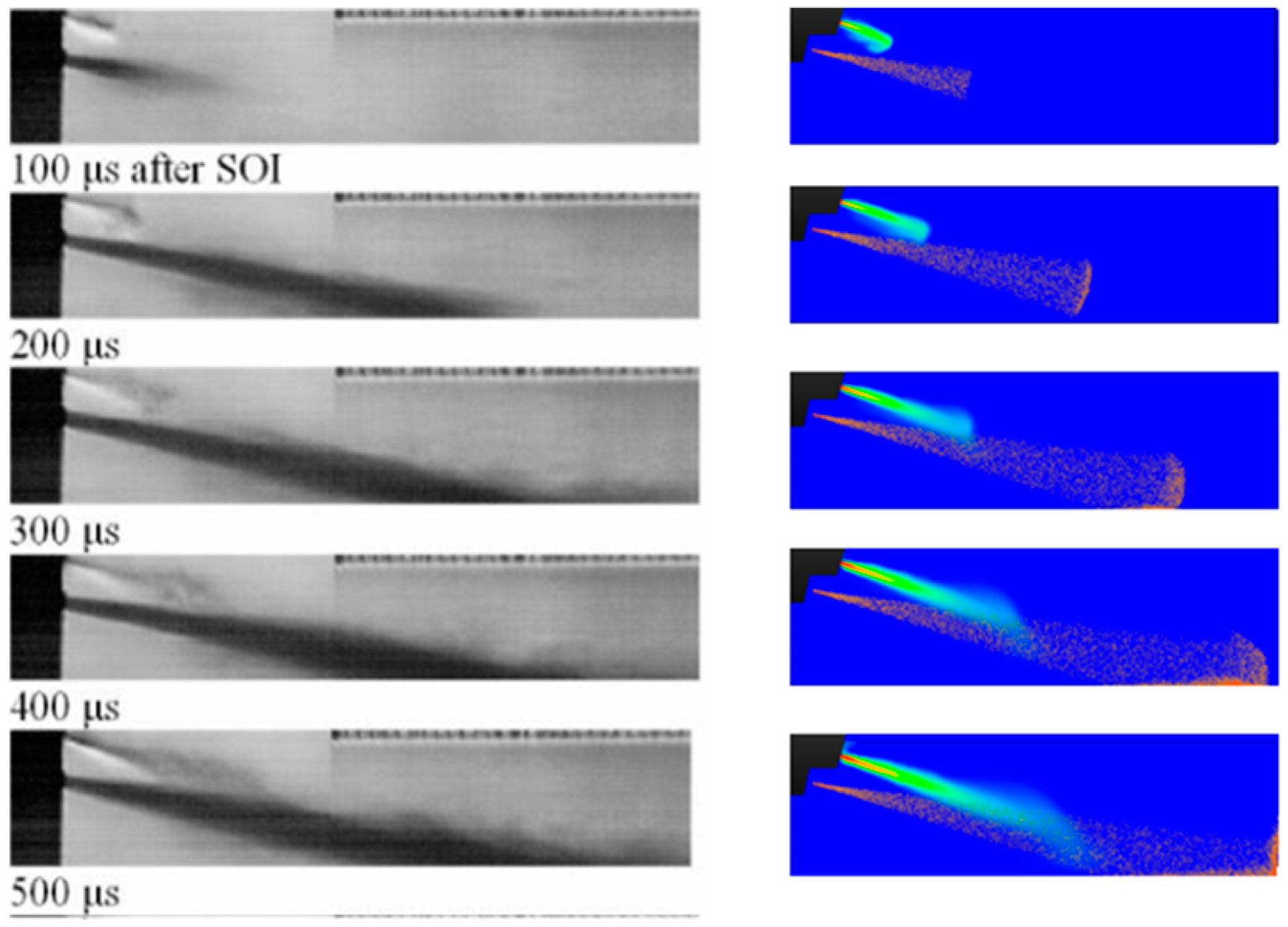
The simulation code used was 3D CFD software COVERGE [43]. It is a finite-volume CFD code capable of simulating three-dimensional incompressible or compressible reacting fluid flows in complex geometries with stationary or moving boundaries. CONVERGE uses an innovative modified cut cell Cartesian method for grid generation with the possibility of adding local refinement and adaptive mesh refinement (AMR) [43,44]. The AMR technique enables local mesh refinement in regions of high temperature and velocity gradients. It is critical to include AMR to capture important flow features without requiring unrealistically large cell counts. As mentioned before, nowadays, natural gas can be produced from various biomass feedstocks [15,16]; moreover, the process of converting biogas into biomethane can be industrialized [45]. Whether it is biomethane or natural gas from fossil energy, its main component is methane [15,16,45,46]. Therefore, methane was used to represent natural gas, whereas n-heptane was used to represent diesel. The physical properties of liquid diesel were represented by those of tetradecane (C14H30). A reduced n-heptane mechanism consisting of 109 species and 334 reactions was used to represent the combustion chemistries of n-heptane and natural gas. Table 2 shows the list of submodels applied for simulation. Additionally, the no-time-counter (NTC) collision method by Schmidt and Rutland was used to describe the droplet collision effects [47]. The spray-wall interaction was simulated using the O’Rourke model [48], and the Kelvin–Helmholtz/Rayleigh–Taylor (KH-RT) model was applied for the spray atomization and breakup simulation [49]. In addition, the mass flow rate was considered to be the boundary condition for the gas fuel injection [50]. The Reynolds-averaged Navier–Stokes (RANS)-based renormalization group (RNG) κ-ε submodel [51] was used to simulate the in-cylinder turbulence. The SAGE solver was adopted to simulate the combustion process [52]. The extended Zeldovich model [53] and Hiroyasu soot model [54] were used to simulate the NOx and soot emissions, respectively. Given that the instantaneous mass flow rate has not been experimentally measured, an assumed injection profile was adopted. As referenced in the works of Scarcelli and colleagues [55,56,57], the injection profile was trapezoidal and the mass flow rate was assumed to be constant with a 1° crank angle (CA) ramp-up and 1° CA ramp-down.
Since CONVERGE does not include a gas injection model, defining the INFLOW boundary method was used to characterize the natural gas injection rate. The injection rate shape of the base case was an isosceles trapezoid.
To validate whether the INFLOW boundary could be used for high-pressure gas injection, the interaction between the gas jet and diesel spray from CFD was compared with results from experiments (Figure 1) [58]. The view chosen to represent the numerical results was in a two-dimensional slice taken through the center of the computational domain. This was, therefore, the same plane upon which lay the axes of both the gas and diesel nozzles. The particles displayed in the slice represented the area density of diesel. Given that the droplets were so finely atomized, light was able to bend enough between the test region and the camera to effectively cover the shadow caused by the droplet. The frames and penetrations of the diesel spray and gas jet for the simulated results were in reasonable agreement with experimental data.
For the engine simulation, the mesh was generated automatically by using an adaptive generation method, with up to 1,500,000 grids.

2.3. Validation

Mesh grid size can significantly affect the computational time and accuracy. Before the CFD model was validated, the mesh grid needed to be selected. Adaptive mesh was adopted to save simulation time and ensure accuracy. The grid can be refined by adjusting the base grid, fixed embedding, and AMR. In this paper, the mesh analysis method was similar to Sun et al. [59]. The exhaust valve, cylinder, scavenge port, and injection were embedded. Given that the calculation time would increase significantly if more refined mesh were used, the base grid of 0.01 m and the AMR of 0.0025 m were adopted to simultaneously maintain the computational accuracy and efficiency.
Figure 2 shows the comparison between the calculated and measured in-cylinder pressure and heat release rate profiles. As seen in the figure, generally good agreement between simulation and experiment was obtained. Detailed comparisons of the main combustion characteristics are presented in Table 3. The maximum error for the maximum in-cylinder pressure (Pmax) phasing was 5.6%, while the simulated combustion phasing (CA50), indicating the specific fuel consumption, and NOx and CO emissions were all very close to those of the experimental data, indicating that the model setup was reasonable and reliable.

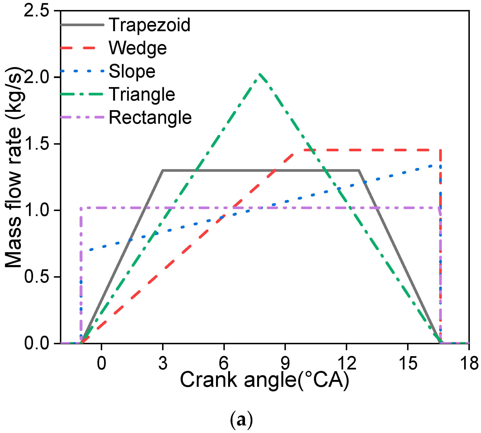
3. Results and Discussion

In this study, five different natural gas injection rate shapes were selected to evaluate the effects of different injection rate shapes on combustion and emission characteristics. Figure 3a shows five different injection rate shapes of natural gas, and Figure 3b shows the cumulative mass flow rate of the corresponding injection rate shapes, wherein the trapezoid shape was the base case.

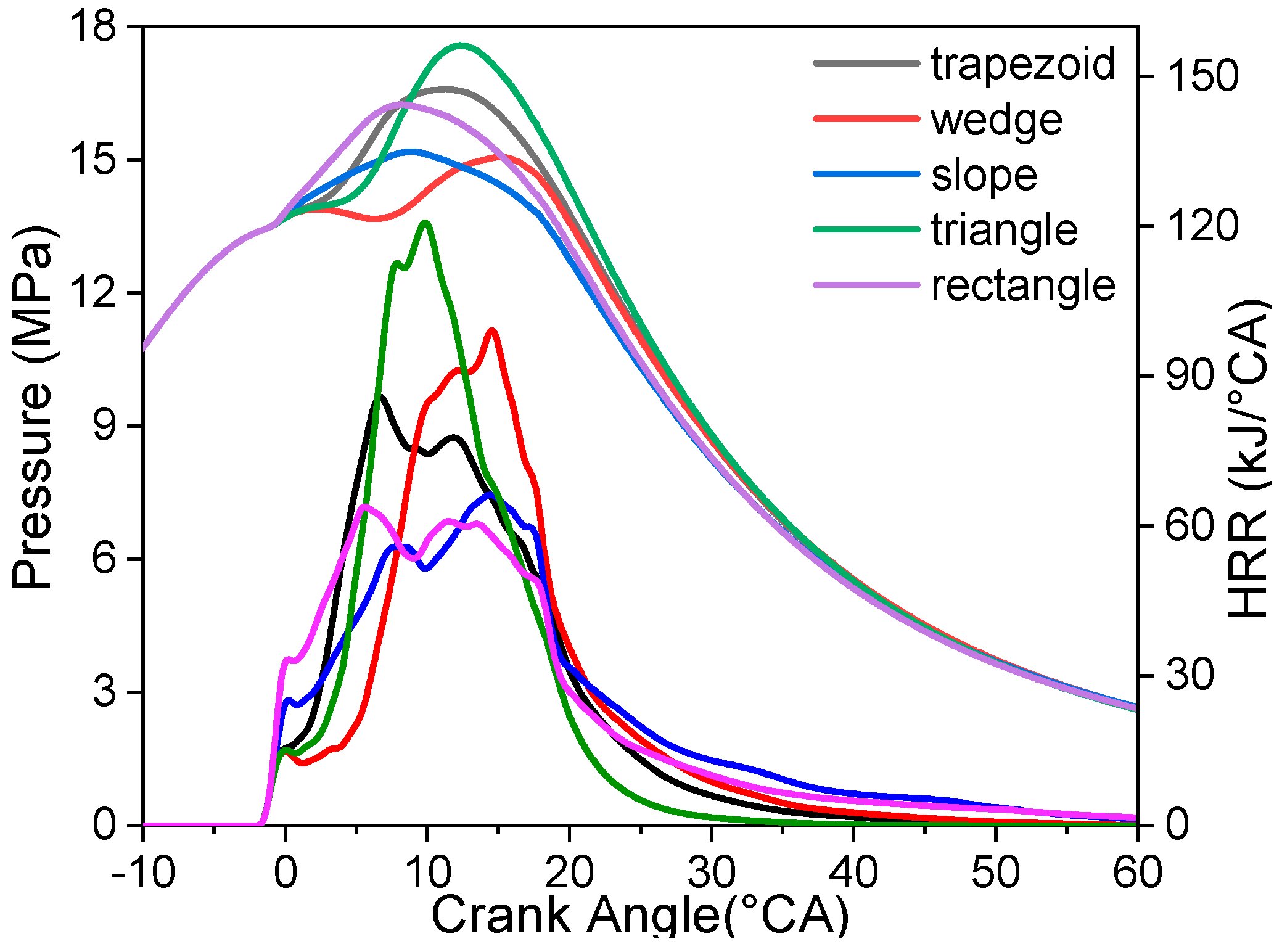
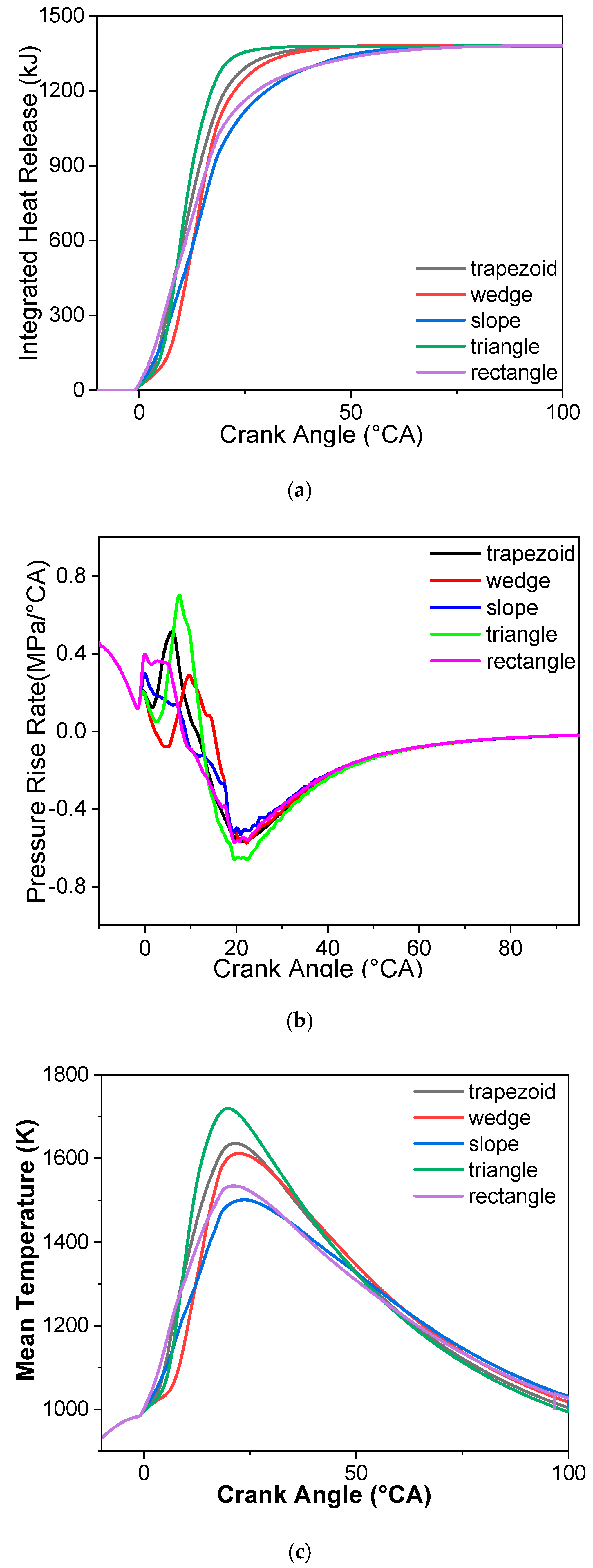
3.1. Combustion Characteristics

The in-cylinder pressure and heat release rate profiles for five different injection rate shapes are shown in Figure 4. It can be seen that the injection rate shape had a significant influence on the heat release rate. Compared with the base case (trapezoid shape), the initial injection rates of the rectangular and sloped shapes were higher, hence the initial heat release rates and initial pressure rise rates also being higher. However, the peaks of in-cylinder pressure profiles were lower and the combustion duration was longer due to the lower maximum injection rates. Since the initial injection rates of the slope shape and rectangle shape were higher compared with the base case, more natural gas was entrained into the diesel–air mixture, and more natural gas was consumed in the initial combustion duration. Therefore, the initial pressure rise and initial heat release rate were higher, while the combustion phase was retarded due to the longer ignition delay periods. Since their initial injection rates were higher, more low-temperature natural gas was entrained into the diesel fuel mixture, the ambient temperature surrounding the diesel was lower, and natural gas consumed OH, thus prolonging the ignition delay periods. Therefore, the peaks of the in-cylinder pressure profile for the slope and rectangle shapes took place in a later phase. The in-cylinder pressure profile illustrated two peak values when adopting a wedge injection rate shape (the initial injection rate was relatively low), where the first peak was a consequence of the end of the compression stroke and the combustion of a small amount of fuel, whereas the second peak induced by the heat released from most of the natural gas occurred after a drop caused by the downward movement of the piston in the expansion stroke. The peaks of the heat release rate profiles for the triangle and wedge shapes were higher than the base case due to their higher maximum injection rates. The highest maximum injection rate of the triangle shape led to the highest peak values of heat release rate and in-cylinder pressure profiles.
The cumulative heat release rate, in-cylinder pressure rise rate, and mean in-cylinder temperature profiles of five different injection rate shapes are shown in Figure 5. It can be seen from the cumulative heat release rate profile that the start of combustion for the triangle shape was later than that of the base case, but it ended earlier, indicating that the combustion duration of the triangle shape was shorter than that of the base case, while the combustion durations of the rectangle and slope shapes were longer than that of the base case (Figure 5a). A short combustion duration results in a reduction of the heat and time losses, resulting in higher thermal efficiency (i.e., lower fuel consumption). An excessively long combustion duration results in lower indicated power and higher indicated specific fuel consumption (ISFC). Figure 6 shows that the slope and rectangle shapes exhibited a lower indicated mean effective pressure (IMEP) and higher ISFC due to their longer combustion duration. The trends of the mean in-cylinder temperature and in-cylinder pressure rise rate profiles were consistent with that of the in-cylinder pressure profiles. The peaks of the mean in-cylinder temperature of all injection rate shapes appeared at about 20° CA ATDC, but the peak values were greatly different. The peak values of the mean in-cylinder temperature and in-cylinder pressure profiles for the triangle shape were the highest, and the peak took place in the earliest phase. The fluctuation ranges of the pressure rise rate profile for the slope shape were minimal in the five injection rate shapes. Since the main combustion process deviated from top dead center, the release of heat took place in a larger volume, and the pressure rise rate was lower. In addition, the trend of ISFC was the opposite of that of IMEP. The triangle shape illustrated a higher IMEP and lower ISFC. This was because the combustion duration of the triangle shape was shorter and the combustion phase was closer to top dead center, which led to a higher mean in-cylinder temperature, while the slope and rectangle shapes exhibited a higher ISFC and a lower IMEP. The ISFCs and IMEPs of the wedge shape and base case were moderate.
The in-cylinder temperature and equivalence ratio distributions from 0.5° to 20.5° CA ATDC are shown in Table 4. The temperature distribution is shown on the left of each slice, and the equivalence ratio distribution is shown on the right. A higher injection rate means a higher gas jet velocity, as well as an enhanced turbulence flow in cylinder, which is beneficial for fuel–air mixing. Moreover, higher gas jet velocity also strengthens in-cylinder turbulence intensity, then accelerates the entrainment process of the unburned mixture into the burning region. Correspondingly, the high-temperature combustion region is larger. As shown in Table 4, the higher initial injection rates of the rectangle and slope shapes led to more low-temperature natural gas being entrained into the burning region or suitable for diesel spontaneous ignition regions; then, the combustion or ignition of pilot diesel was suppressed. Thus, the high equivalence ratio region was wider and the high-temperature region almost disappeared at 0.5° CA ATDC (natural gas was just injected into the cylinder at this moment). On the contrary, the high equivalence ratio regions of the wedge and triangle shapes were concentrated near the nozzle due to lower initial injection rate. Therefore, the initial combustion processes of pilot diesel were almost not affected and high-temperature regions were larger. At 5.5° CA ATDC, the equivalence ratio distribution of the rectangle shape was widest, and the high-temperature combustion region was largest. At this moment, the injection rate of the base case was higher than the rectangle case, and the combustion region was similar to that of the rectangle shape. However, the equivalence ratio distribution and high-temperature combustion region were smaller than those of the rectangle case. At 10.5° CA ATDC, the equivalence ratio distribution of the triangle shape was wider due to its higher maximum injection rate, hence the high-temperature combustion region of the triangle shape being larger than those of the other cases. However, more NOx formed in the larger high-temperature region. In the late stage of gas injection, the wedge, slope, and rectangle shapes still maintained a higher injection rate. The high equivalence ratio regions were exhibited near the natural gas injector. Therefore, the combustion processes were more intense than those of the other two cases. However, the intense combustion was not conducive to power output because the combustion phase deviated from top dead center. In addition, the air flow (in the black circle) outside of the gas jet was less affected by the gas jet, and the fuel–air mixing was worse. In other words, the fuel was concentrated in a relatively small region, which was not suitable for combustion; hence, the UHC emissions were higher.

3.2. Emissions

Since Tier III emission regulations were implemented in 2016, the emissions of marine engines are further limited [60]. Therefore, the emissions of HPDI natural gas marine engines are an important indicator for evaluating these engines. The common emissions of five different injection shapes are compared in Figure 7. The NOx emissions of HPDI natural gas marine engines can meet Tier II emission regulations without any optimized strategy, which is better than traditional diesel engines. However, the NOx–ISFC trade-off is not eliminated. NOx formation is mainly related to high temperature, oxygen concentration, and high-temperature duration. The high-temperature region of the triangle shape was the largest, and it maintained a long duration; hence, the NOx emissions were the highest. The NOx emissions of the rectangle and slope shapes were lower due to their lower mean in-cylinder temperatures. The NOx and soot emissions of the wedge shape were slightly lower than those of the base case, while ISFC was just slightly higher than that of the base case. The potential of the wedge shape to reduce NOx emissions can be further explored. The soot emissions of the HPDI natural gas marine engine are much lower than those of a traditional diesel engine. However, the NOx–soot trade-off is unmitigated. The soot emissions of the rectangle shape were the highest, and those of trapezoid, wedge, and triangle shapes were lower. On one hand, the higher initial injection rate of the rectangle had a negative effect on the combustion of pilot diesel and the subsequent combustion temperature was lower. On the other hand, the higher initial injection rate resulted in a high equivalence ratio region, which was suitable for soot generation in moderate-temperature high equivalence ratio regions. Additionally, the whole combustion temperature of the rectangle shape was relatively low, which was not conducive to oxidation of soot; thus, soot emissions were higher for the rectangle shape. Table 5 shows the soot (left) and NOx (right) distributions at 0.5°, 10.5°, 20.5°, and 30.5° CA ATDC for the five injection rate shapes. The temperature and equivalence ratio distributions in Table 4 show that the high equivalence ratio regions of the trapezoid, wedge, and triangle shapes were relatively smaller at the initial injection stage; thus, the initial combustion regions were smaller. However, the combustion temperatures of pilot diesel in these three cases were higher. Therefore, the NOx emissions were higher than the other two cases, whereas the soot emissions were lower. A higher gas jet velocity promotes natural gas–air mixing, and the equivalence ratio distribution suitable for combustion is larger. Meanwhile, the high injection rate enhances in-cylinder turbulence flow, and the higher turbulence intensity promotes the entrainment effect of the unburned mixture into the burning regions. Therefore, a better combustion process is achieved. Hence, the NOx distribution of the triangle shape was the highest. The oxidations of soot for the rectangle and slope shapes were slow due to their lower combustion temperature in the late combustion stage. Therefore, the soot concentrated near the cylinder wall for the rectangle and slope shapes at 20.5° CA ATDC due to their lower temperature near the wall.
CO and HC are the intermediate species of the oxidation of fuel, and their fluctuations are consistent with soot emissions. The CO + HC emissions of the rectangle shape were highest owing to its lowest mean in-cylinder temperature and lower maximum injection rate. The lowest mean in-cylinder temperature indicated that the in-cylinder reaction rates were slower, and the lower injection rate led to fuels concentrating in a small region. More fuels were consumed in incomplete combustion as a consequence of the above two effects; thus, CO + HC emissions were higher. The CO + HC emissions of the triangle shape were the lowest due to its highest maximum injection rate and highest peak value of mean in-cylinder temperature profile. The maximum injection rate and the peak values of mean in-cylinder temperature profiles for the trapezoid and wedge shapes were slightly lower than those of the triangle shape but higher than those of the other two cases. Therefore, CO + HC emissions were slightly higher than the triangle shape but lower than the other two cases. Methane (CH4) is a greenhouse gas, which has a greater effect than CO2. Since CH4 is the primary component of natural gas, CH4 emissions are directly related to ISFC. The trend of CH4 emissions was associated with the emissions of soot and CO + HC. The CH4 emissions of the triangle shape were relatively low, and the CH4 emissions of the wedge shape and base case were just slightly higher than those of the triangle shape. It should be noted that the impact of natural gas leakage was not considered in the simulation. CH4 emissions are derived from unburned methane in the excessively lean equivalence ratio regions. The flammability limit of methane is relatively wide [61], hence the calculated CH4 emissions being lower than the experiment (2 g/kW·h). Figure 8 compares the formation of the main intermediate species of the rectangle shape (a) and the triangle shape (b). C7, C5, and C4 of the rectangle shape were higher. Since lower alkanes are difficult to combine into higher alkanes, the C7, C5, and C4 were mainly derived from the oxidation of diesel. Due to higher initial injection rate of the rectangle shape, more low-temperature natural gas was entrained into the burning region, which had a negative effect on combustion. The intermediate species with a high carbon number increased, which was consistent with combustion analysis discussed in Section 3.1. Therefore, a lower initial gas injection rate is beneficial for reducing CO + HC emissions.

4. Conclusions

The injection rate shape has a great influence on the combustion and emissions of dual-fuel marine engines. In the current study, numerical investigations were conducted to study the influences of different injection rate shapes on the combustion and emission characteristics of a large-bore two-stroke natural gas/diesel dual-fuel marine engine. The major results can be summarized as follows:
(1) Compared with the trapezoid shape, the triangle shape had a higher peak value of in-cylinder pressure and heat release rate profiles due to its highest peak value of gas injection rate, and the phase of the peak value was close to top dead center. Meanwhile, the mean in-cylinder temperature and IMEP were higher. Conversely, the ISFC was lower. However, the higher combustion temperature of the triangle shape also led to higher NOx emissions.
(2) The lower NOx emissions of the rectangle and slope shapes were beneficial due the lower combustion temperature, but their ISFCs increased. The emissions of soot, CO + HC, and CH4 of the rectangle and slope shapes were higher.
(3) The wedge and trapezoid shapes achieved a good balance between ISFC and emissions. However, other abatement technology must be applied to meet Tier III emission regulations.

Author Contributions

Data curation, J.W.; Funding acquisition, J.D., B.L. and C.W.; Investigation, J.L. and H.L.; Methodology, J.W., Y.Y. and H.W.; Resources, C.W., J.D. and C.W.; Writing—original draft, J.L.; Writing—review & editing, H.L.

Funding

his work was supported by the high-tech Ship Research Program of MIIT, which is a prototype research study of 400 mm natural gas dual-fuel marine engines (phase I of the Marine Low-Speed Engine Project).

Conflicts of Interest

The authors declare no conflict of interests.

References

  1. IMO, A.V. 73/78 Regulations for the Prevention of Air Pollution from Ships and NOx Technical Code; International Maritime Organization: London, UK, 1998. [Google Scholar]
  2. Krivopolianskii, V.; Valberg, I.; Stenersen, D.; Ushakov, S.; Æsøy, V. Control of the combustion process and emission formation in marine gas engines. J. Mar. Sci. Technol. 2018, 24, 593–611. [Google Scholar] [CrossRef]
  3. Shen, Z.; Cui, W.; Ju, X.; Liu, Z.; Wu, S.; Yang, J. Numerical Investigation on Effects of Assigned EGR Stratification on a Heavy Duty Diesel Engine with Two-Stage Fuel Injection. Energies 2018, 11, 515. [Google Scholar] [CrossRef]
  4. Dnv, G. IMO NOx Tier III Requirements to Take Effect on 1 January 2016. Available online: https://www.dnvgl.com/news/imo-nox-tier-iii-requirements-to-take-effect-on-january-1st-2016-51970 (accessed on 17 December 2015).
  5. Kim, D.; Lee, C. SCR Performance Evaluations in Relation to Experimental Parameters in a Marine Generator Engine. J. Mar. Sci. Eng. 2019, 7, 67. [Google Scholar] [CrossRef]
  6. Wu, Y.Y.; Jang, C.T. Combustion Analysis of Homogeneous Charge Compression Ignition in a Motorcycle Engine Using a Dual-Fuel with Exhaust Gas Recirculation. Energies 2019, 12, 847. [Google Scholar] [CrossRef]
  7. Mahmoudzadeh, A.A.; Pesyridis, A.; Esfahanian, V.; Said, M.F.M. Combustion and Emission Enhancement of a Spark Ignition Two-Stroke Cycle Engine Utilizing Internal and External Exhaust Gas Recirculation Approach at Low-Load Operation. Energies 2019, 12, 609. [Google Scholar] [CrossRef]
  8. Chala, G.; Abd Aziz, A.; Hagos, F. Natural Gas Engine Technologies: Challenges and Energy Sustainability Issue. Energies 2018, 11, 2934. [Google Scholar] [CrossRef]
  9. Brynolf, S.; Magnusson, M.; Fridell, E.; Andersson, K. Compliance possibilities for the future ECA regulations through the use of abatement technologies or change of fuels. Transp. Res. Part D Transp. Environ. 2014, 28, 6–18. [Google Scholar] [CrossRef]
  10. Briggs, J.; McCarney, J. Field experience of Marine SCR. In Proceedings of the CIMAC Congress 2016, Helsinki, Finland, 6–10 June 2016. [Google Scholar]
  11. Zamboni, G. Influence of Fuel Injection, Turbocharging and EGR Systems Control on Combustion Parameters in an Automotive Diesel Engine. Appl. Sci. 2019, 9, 484. [Google Scholar] [CrossRef]
  12. Park, S.; Lee, K.; Park, J. Parametric Study on EGR Cooler Fouling Mechanism Using Model Gas and Light-Duty Diesel Engine Exhaust Gas. Energies 2018, 11, 3161. [Google Scholar] [CrossRef]
  13. Zheng, J.; Hu, E.; Huang, Z.; Ning, D.; Wang, J. Combustion and emission characteristics of a spray guided direct-injection spark-ignition engine fueled with natural gas-hydrogen blends. Int. J. Hydrogen Energy 2011, 36, 11155–11163. [Google Scholar] [CrossRef]
  14. Xu, M.; Cheng, W.; Zhang, H.; An, T.; Zhang, S. Effect of diesel pre-injection timing on combustion and emission characteristics of compression ignited natural gas engine. Energy Convers. Manag. 2016, 117, 86–94. [Google Scholar] [CrossRef]
  15. Papagiannakis, R.; Rakopoulos, D.; Rakopoulos, C. Evaluation of the Air Oxygen Enrichment Effects on Combustion and Emissions of Natural Gas/Diesel Dual-Fuel Engines at Various Loads and Pilot Fuel Quantities. Energies 2018, 11, 3028. [Google Scholar] [CrossRef]
  16. Gaikwad, M.S.; Jadhav, K.M.; Kolekar, A.H.; Chitragar, P.R. Combustion characteristics of biomethane–diesel dual-fueled CI engine with exhaust gas recirculation. Biofuels 2018. [Google Scholar] [CrossRef]
  17. Abdelaal, M.M.; Hegab, A.H. Combustion and emission characteristics of a natural gas-fueled diesel engine with EGR. Energy Convers. Manag. 2012, 64, 301–312. [Google Scholar] [CrossRef]
  18. Chen, Z.; Zhang, F.; Xu, B.; Zhang, Q.; Liu, J. Influence of methane content on a LNG heavy-duty engine with high compression ratio. Energy 2017, 128, 329–336. [Google Scholar] [CrossRef]
  19. Liu, J.; Zhang, X.; Wang, T.; Zhang, J.; Wang, H. Experimental and numerical study of the pollution formation in a diesel/CNG dual fuel engine. Fuel 2015, 159, 418–429. [Google Scholar] [CrossRef]
  20. Liu, J.; Wang, J.; Zhao, H. Optimization of the injection parameters and combustion chamber geometries of a diesel/natural gas RCCI engine. Energy 2018, 164, 837–852. [Google Scholar] [CrossRef]
  21. Zhang, Q.; Li, M.; Shao, S. Combustion process and emissions of a heavy-duty engine fueled with directly injected natural gas and pilot diesel. Appl. Energy 2015, 157, 217–228. [Google Scholar] [CrossRef]
  22. Liu, J.; Zhao, H.; Wang, J.; Zhang, N. Optimization of the injection parameters of a diesel/natural gas dual fuel engine with multi-objective evolutionary algorithms. Appl. Therm. Eng. 2019, 150, 70–79. [Google Scholar] [CrossRef]
  23. Juliussen, L.; Kryger, M.; Andreasen, A. Man B&W Me-Gi engines. recent research and results. In Proceedings of the International Symposium of Marine Engineering, Kobe, Japan, 17–21 October 2011. [Google Scholar]
  24. Juliussen, L.; Mayer, S.; Kryger, M. The MAN ME-GI engine: From initial system considerations to implementation and performance optimization. In Proceedings of the CIMAC Congress 2016, Helsinki, Finland, 6–10 June 2016. [Google Scholar]
  25. Klausner, J.; Trapp, C.; Schaumberger, H. The gas engine of the future–innova-tive combustion and high compression ratios for highest efficiencies. In Proceedings of the CIMAC Congress 2010, Bergen, Norway, 14–17 June 2010. [Google Scholar]
  26. Nylund, I.; Ott, M. Development of a Dual Fuel technology for slow-speed engines. In Proceedings of the CIMAC Congress 2013, Shanghai, China, 13–16 May 2013. [Google Scholar]
  27. Redtenbacher, C.; Kiesling, C.; Wimmer, A.; Sprenger, F.; Fasching, P.; Eichelseder, H. Dual Fuel Brennverfahren-Ein Zukunftsweisendes Konzept Vom PKW-Bis Zum Großmotorenbereich? In Proceedings of the 37th International Vienna Motor Symposium, Vienna, Austria, 28–29 April 2016; pp. 403–428. [Google Scholar]
  28. Eder, L.; Ban, M.; Pirker, G.; Vujanovic, M.; Priesching, P.; Wimmer, A. Development and Validation of 3D-CFD Injection and Combustion Models for Dual Fuel Combustion in Diesel Ignited Large Gas Engines. Energies 2018, 11, 643. [Google Scholar] [CrossRef]
  29. He, Z.; Xuan, T.; Xue, Y.; Wang, Q.; Zhang, L. A numerical study of the effects of injection rate shape on combustion and emission of diesel engines. Therm. Sci. 2014, 18, 67–78. [Google Scholar] [CrossRef] [Green Version]
  30. Rohani, B.; Bae, C. Effect of exhaust gas recirculation (EGR) and multiple injections on diesel soot nano-structure and reactivity. Appl. Therm. Eng. 2017, 116, 160–169. [Google Scholar] [CrossRef]
  31. Hinkelbein, J.; Sandikcioglu, C.; Pischinger, S.; Lamping, M.; Körfer, T. Control of the diesel combustion process via advanced closed loop combustion control and a flexible injection rate shaping tool. SAE Int. J. Fuels Lubr. 2010, 2, 362–375. [Google Scholar] [CrossRef]
  32. Bai, F.; Zhang, Z.; Du, Y.; Zhang, F.; Peng, Z. Effects of injection rate profile on combustion process and emissions in a diesel engine. J. Combust. 2017. [Google Scholar] [CrossRef]
  33. Mohan, B.; Yang, W.; Yu, W.; Tay, K.L.; Chou, S.K. Numerical investigation on the effects of injection rate shaping on combustion and emission characteristics of biodiesel fueled CI engine. Appl. Energy 2015, 160, 737–745. [Google Scholar] [CrossRef]
  34. Macian, V.; Payri, R.; Ruiz, S.; Bardi, M.; Plazas, A.H. Experimental study of the relationship between injection rate shape and Diesel ignition using a novel piezo-actuated direct-acting injector. Appl. Energy 2014, 118, 100–113. [Google Scholar] [CrossRef]
  35. Shuai, S.; Abani, N.; Yoshikawa, T.; Reitz, R.D.; Park, S.W. Evaluation of the effects of injection timing and rate-shape on diesel low temperature combustion using advanced CFD modeling. Fuel 2009, 88, 1235–1244. [Google Scholar] [CrossRef]
  36. Hountalas, D.T.; Kouremenos, D.A.; Pariotis, E.G.; Schwarz, V.; Binder, K.B. Using a phenomenological multi-zone model to investigate the effect of injection rate shaping on performance and pollutants of a DI heavy duty diesel engine. SAE Trans. 2002, 111, 358–375. [Google Scholar]
  37. Benajes, J.; Payri, R.; Molina, S.; Soare, V. Investigation of the influence of injection rate shaping on the spray characteristics in a diesel common rail system equipped with a piston amplifier. J. Fluids Eng. 2005, 127, 1102–1110. [Google Scholar] [CrossRef]
  38. Kohketsu, S.; Tanabe, K.; Mori, K. Flexibly controlled injection rate shape with next generation common rail system for heavy duty DI diesel engines. SAE Trans. 2000, 109, 459–468. [Google Scholar]
  39. Desantes, J.M.; Benajes, J.; Molina, S.; Gonzalez, C.A. The Modification of the Fuel Injection Rate in Heavy-Duty Diesel Engines, Part 1: Effects on Engine Performance and Emissions. Appl. Therm. Eng. 2004, 24, 2701–2714. [Google Scholar] [CrossRef]
  40. Desantes, J.M.; Benajes, J.; Molina, S.; Gonzalez, C.A. The Modification of the Fuel Injection Rate in Heavy-Duty Diesel Engines, Part 2: Effects on Combustion. Appl. Therm. Eng. 2004, 24, 2715–2726. [Google Scholar] [CrossRef]
  41. Luckhchoura, V. Modeling of Injection-Rate Shaping in Diesel Engine Combustion. Ph.D. Thesis, RWTH Aachen University, Aachen, Germany, 2010. [Google Scholar]
  42. Turbo, M.D. Basic Principles of Ship Propulsion. Available online: https://marine.man-es.com/propeller-aftship/basicprinciples-of-propulsion (accessed on 17 October 2018).
  43. Richards, K.J.; Senecal, P.K.; Pomraning, E. CONVERGE Manual (Version 2.3); Convergent Science Inc.: Madison, WI, USA, 2016. [Google Scholar]
  44. Senecal, P.K.; Richards, K.J.; Pomraning, E.; Yang, T.; Dai, M.Z.; McDavid, R.M.; Shethaji, T. A new parallel cut-cell Cartesian CFD code for rapid grid generation applied to in-cylinder diesel engine simulations. SAE Tech. Pap. 2007, 1, 159. [Google Scholar]
  45. Ashok, B.; Nanthagopal, K. Eco friendly biofuels for CI engine applications. In Advances in Eco-Fuels for a Sustainable Environment; Azad, K., Ed.; Woodhead Publishing: Amsterdam, The Netherlands, 2019; pp. 407–440. [Google Scholar]
  46. Golimowski, W.; Krzaczek, P.; Marcinkowski, D.; Gracz, W.; Wałowski, G. Impact of Biogas and Waste Fats Methyl Esters on NO, NO2, CO, and PM Emission by Dual Fuel Diesel Engine. Sustainability 2019, 11, 1799. [Google Scholar] [CrossRef]
  47. Schmidt, D.P.; Rutland, C.J. A new droplet collision algorithm. J. Comput. Phys. 2000, 164, 62–80. [Google Scholar] [CrossRef]
  48. O’Rourke, P.J.; Amsden, A.A. A spray/wall interaction submodel for the KIVA-3 wall film model. SAE Trans. 2000, 109, 281–298. [Google Scholar]
  49. Beale, J.C.; Reitz, R.D. Modeling spray atomization with the Kelvin-Helmholtz/Rayleigh-Taylor hybrid model. At. Sprays 1999, 9. [Google Scholar] [CrossRef]
  50. Le Moine, J.; Senecal, P.K.; Kaiser, S.A.; Salazar, V.M.; Anders, J.W.; Svensson, K.I.; Gehrke, C.R. A Computational Study of the Mixture Preparation in a Direct–Injection Hydrogen Engine. J. Eng. Gas Turbines Power 2015, 137, 111508. [Google Scholar] [CrossRef]
  51. Yakhot, V.; Orszag, S.A. Renormalization group analysis of turbulence. I. Basic theory. J. Sci. Comput. 1986, 1, 3–51. [Google Scholar] [CrossRef]
  52. Dukowicz, J.K. A particle-fluid numerical model for liquid sprays. J. Comput. Phys. 1980, 35, 229–253. [Google Scholar] [CrossRef]
  53. Maroteaux, F.; Saad, C. Combined mean value engine model and crank angle resolved in-cylinder modeling with NOx emissions model for real-time Diesel engine simulations at high engine speed. Energy 2015, 88, 515–527. [Google Scholar] [CrossRef]
  54. Paykani, A.; Kakaee, A.H.; Rahnama, P.; Reitz, R.D. Effects of diesel injection strategy on natural gas/diesel reactivity controlled compression ignition combustion. Energy 2015, 90, 814–826. [Google Scholar] [CrossRef]
  55. Scarcelli, R.; Wallner, T.; Matthias, N.; Salazar, V.; Kaiser, S. Mixture formation in direct injection hydrogen engines: CFD and optical analysis of single-and multi-hole nozzles. SAE Int. J. Engines 2011, 4, 2361–2375. [Google Scholar] [CrossRef]
  56. Scarcelli, R.; Wallner, T.; Matthias, N.; Salazar, V.; Kaiser, S. Numerical and optical evolution of gaseous jets in direct injection hydrogen engines. SAE Tech. Pap. 2011, 1, 675. [Google Scholar]
  57. Scarcelli, R.; Wallner, T.; Obermair, H.; Salazar, V.M.; Kaiser, S.A. CFD and optical investigations of fluid dynamics and mixture formation in a DI-H2ICE. In Proceedings of the ASME 2010 Internal Combustion Engine Division Fall Technical Conference, San Antonio, TX, USA, 12–15 September 2010; American Society of Mechanical Engineers: New York, NY, USA, 2010; pp. 175–188. [Google Scholar]
  58. White, T.R. Simultaneous Diesel and Natural Gas Injection for Dual-Fueling Compression-Ignition Engines; University of New South Wales: Sydney, Australia, 2006. [Google Scholar]
  59. Sun, X.; Liang, X.; Shu, G.; Wang, Y.; Wang, Y.; Yu, H. Effect of different combustion models and alternative fuels on two-stroke marine diesel engine performance. Appl. Therm. Eng. 2017, 115, 597–606. [Google Scholar] [CrossRef]
  60. Emission Standards. IMO Marine Engine. Available online: http://www.DieselNet.com/standards (accessed on 13 August 2011).
  61. Chen, Z. Effects of radiation and compression on propagating spherical flames of methane/air mixtures near the lean flammability limit. Combust. Flame 2010, 157, 2267–2276. [Google Scholar] [CrossRef]
Figure 1. Comparison of interaction between gas jet and diesel spray: experimental data on the left and simulation result on the right.
Energies 12 02571 g001
Figure 2. Comparisons between the calculated and measured in-cylinder pressure and HRR traces.
Energies 12 02571 g002
Figure 3. Five different gas injection rate shapes (a) and their corresponding cumulative flow (b).
Energies 12 02571 g003aEnergies 12 02571 g003b
Figure 4. The in-cylinder pressure and HRR profiles for different injection rate shapes.
Energies 12 02571 g004
Figure 5. The effects of different injection rate shapes on (a) integrated heat release, (b) pressure rise rate, (c) and in-cylinder mean temperature.
Energies 12 02571 g005
Figure 6. The effects of different injection rate shapes on indicated mean effective pressure (IMEP) and indicated specific fuel consumption (ISFC).
Energies 12 02571 g006
Figure 7. The effects of injection rate shapes on (a) NOx, soot, hydrocarbon (HC), and (b) CH4 emissions.
Energies 12 02571 g007
Figure 8. The trace comparison of main intermediate species for the rectangle (a) and triangle (b) shapes.
Energies 12 02571 g008
Table 1. Main specifications of the 4T50ME-GI research engine [23].
ParametersValue
Type4T50ME-GI
Number of cylinders4
Bore/stroke500/2200 mm
Connecting rod2885 mm
Geometric compression ratio18.14
Engine speed @ MCR123 rpm
Power @ MCR7050 kW
IMEP @ MCR20 bar
TurbochargerMAN TCA55-VTA
Table 2. List of submodels used in the simulation.
PhenomenonModelReference
Droplet collisionNTC collision method[47]
Spray–wall interactionO’Rourke model[48]
Spray atomization and breakupHybrid KH-RT[49]
Gas injectionInflow boundary[50]
TurbulenceRNG κ-ε model[51]
CombustionSAGE[52]
NOxExtended Zeldovich model[53]
SootHiroyasu soot model[54]
Table 3. Comparison between the calculated and measured parameters.
ExperimentSimulationError
Pmax (MPa)16.8216.7640.33%
Pmax phase (°CA ATDC)11.4410.85.6%
CA50(°CA)11.511.22.6%
λ2.452.42%
ISFC(g/kWh)163.2162.2540.58%
Power output(kW)53315390.5671%
NOx (g/kWh)11.911.6212.3%
CO (g/kWh)0.190.1921%
Table 4. The in-cylinder temperature (left) and equivalent ratio (right) distributions for different gas injection rate shapes.
ATDCTrapezoidWedgeSlopeTriangleRectangle
0.5° CA Energies 12 02571 i001 Energies 12 02571 i002 Energies 12 02571 i003 Energies 12 02571 i004 Energies 12 02571 i005
5.5° CA Energies 12 02571 i006 Energies 12 02571 i007 Energies 12 02571 i008 Energies 12 02571 i009 Energies 12 02571 i010
10.5° CA Energies 12 02571 i011 Energies 12 02571 i012 Energies 12 02571 i013 Energies 12 02571 i014 Energies 12 02571 i015
15.5° CA Energies 12 02571 i016 Energies 12 02571 i017 Energies 12 02571 i018 Energies 12 02571 i019 Energies 12 02571 i020
20.5° CA Energies 12 02571 i021 Energies 12 02571 i022 Energies 12 02571 i023 Energies 12 02571 i024 Energies 12 02571 i025
Energies 12 02571 i026
Table 5. The distribution of soot (left) and NOx (right) distributions at 0.5°, 10.5°, 20.5°, and 30.5° CA ATDC for different injection rate shapes.
ATDCTrapezoidWedgeSlopeTriangleRectangle
0.5
deg
Energies 12 02571 i027 Energies 12 02571 i028 Energies 12 02571 i029 Energies 12 02571 i030 Energies 12 02571 i031
10.5
deg
Energies 12 02571 i032 Energies 12 02571 i033 Energies 12 02571 i034 Energies 12 02571 i035 Energies 12 02571 i036
20.5
deg
Energies 12 02571 i037 Energies 12 02571 i038 Energies 12 02571 i039 Energies 12 02571 i040 Energies 12 02571 i041
30.5
deg
Energies 12 02571 i042 Energies 12 02571 i043 Energies 12 02571 i044 Energies 12 02571 i045 Energies 12 02571 i046
Energies 12 02571 i047

