Article

Study on Size Design of Shaft Protection Rock/Coal Pillars in Thick Soil and Thin Rock Strata

1
State Key Laboratory for Geomechanics and Deep Underground Engineering, China University of Mining and Technology, Xuzhou 221116, Jiangsu Province, China
2
School of Mechanics and Civil Engineering, China University of Mining and Technology, Xuzhou 221116, Jiangsu Province, China
*
Authors to whom correspondence should be addressed.
Energies 2019, 12(13), 2553; https://doi.org/10.3390/en12132553
Submission received: 28 May 2019 / Revised: 28 June 2019 / Accepted: 1 July 2019 / Published: 2 July 2019
(This article belongs to the Special Issue Green Coal Mining Techniques)

Abstract

:
To prevent serious shaft deflection disasters under asymmetric mining conditions, it is urgent to solve the problem of designing shaft protection rock pillar (SPRP) sizes in thick soil and thin rock strata. In this paper, based on the parallel mining model and the perpendicular mining model, a dynamic prediction model that can describe the horizontal movement of the shaft was established by the probability integration method and the Knothe time function. Next, according to the measured data of the shaft deflection in the Guotun Coal Mine, a back analysis was used to calculate the prediction parameters that were suitable for the deep soil strata. Based on the mining model, the variation law of the horizontal deflection displacement of the shaft and SPRP size was obtained. The results showed that the final displacements of the shaft under the two ideal mining models were equal, while the parallel mining model was superior to the perpendicular mining model at the initial stage of mining. The horizontal displacement of the shaft head had a nonlinear negative correlation with the SPRP, and the SPRP size in thick soil and thin rock strata calculated by the parallel mining model was more reasonable. For the Guotun Coal Mine, when the soil movement angle was 57.8% of the actual value, the horizontal displacement of the main shaft head was reduced by 87%. The results have important theoretical and practical value in preventing shaft deflection in thick soil and thin rock strata.

1. Introduction

Since 2002, a large number of vertical shafts have been built in deep soil strata in China. There are 71, 28, 4, and 3 shafts with soil thicknesses greater than 400, 500, 600, and 700 m, respectively, and the maximum soil thickness is 754.98 m (the main shaft of the Wanfu Coal Mine in Shandong Province). Additionally, vertical shafts with soil thicknesses exceeding half the total depth account for 86% of the 71 shafts (see Figure 1). As the shaft is the “throat” of a coal mine, its safety is vital to the survival of the entire mine. However, underground mining activities may cause the shaft to deflect and subside, which significantly affects hoisting safety and poses a great threat to lining safety. To protect the shaft from the effects of mining activities, a shaft protection coal pillar (SPCP) or shaft protection rock pillar (SPRP) must be retained. The design methods for SPCPs are basically similar, and existing SPCPs are mostly designed by experience or angles. Due to the large size of SPCPs designed by empirical methods, the boundary angle or the movement angle has been used to design SPCPs in European coal mines [1] and is stipulated in existing criteria [2] and manuals [3] in China. Much research has been carried out on the design of SPCPs. Zeenke et al. studied the shape and size of SPCPs in the Ostrava–Karvin Coal Mine and discussed the combination of the SPCP boundary delineated by the pillar angle under different dip angles [4]. Haupt et al. calculated the SPCP size under single or multiple seam mining conditions using the Elhart–Shaoer method with predetermined boundary values [5]. Kratzsch believed that an insufficient SPCP size is the main cause of shaft damage during mining and proposed some measures based on different mining conditions and lining types, such as setting a sliding layer, separating seam, and compressible wood cushion in the shaft lining [6]. Considering the predicted shaft deformation insurance coefficient, Sroka determined the movement angles by using the critical deformation value and obtained a formula for calculating the SPCP based on observation data of SPCP mining in Germany and Poland [7]. Wei et al. studied the influence factors and change law of SPCP size and obtained a more realistic nonlinear formula for calculating SPCP size [8]. In addition, based on the vertical section method, Wei et al. analyzed the shortcomings of the existing graphic method and established an analytical mathematical model of designing SPCPs [9]. With comprehensive analysis of a large number of field observation data and mining slip mechanisms and sliding vectors, He et al. established a mathematical model for estimating the SPCP that is suitable for mountainous areas [10]. However, the above research was conducted under thin soil strata conditions. In addition, the existing movement angles both in China and internationally are the observations in the case of thin soil strata [11]. As seen in Table 1, for different mining conditions, the movement angles of some mine areas in China are basically unchanged. The result is that the SPRP size designed by existing movement angles is obviously insufficient in deep soil strata, resulting in the shaft being within the range of mining influence, and mining activity causes the soil around the shaft at different depths to produce different displacement values. Under asymmetric mining conditions, the shaft will be deflected as same as that in the Guotun Coal Mine. To prevent serious shaft deflection disasters, it is urgent to solve the problem of designing SPRP sizes in thick soil and thin rock strata.
We addressed this issue in this study by, first, establishing two more ideal mining models than actual mining according to the general mining law. Based on this, a dynamic prediction model that can describe the horizontal movement of the shaft was obtained by combining the probability integral method with the Knothe time function. Second, for the main shaft deflection in the Guotun Coal Mine, a back analysis was adopted to calculate prediction parameters that are suitable for deep soil strata. Finally, the relationship between the SPRP size and the deflection displacement of the main shaft was obtained by using the ideal mining model. By analyzing their relationships, a more reasonable SPRP size than that from the specification design was obtained. The results have important guiding significance for protecting lining safety and preventing shaft deflection disasters, and they can also provide a scientific and theoretical basis for mining SPCPs.

2. Project Case

The main shaft, the auxiliary shaft, and the air shaft of the Guotun Coal Mine in Shandong Province are located to the side of the coal-free area. The design parameters are as follows: The width of the enclosure belt is 20 m, and the movement angles of the soil and the rock are 45° and 70°, respectively. Therefore, the minimum distance from the main shaft to the coal pillars is approximately 858 m. The auxiliary shaft is 92 m ES49° away from the main shaft. The shafts in the Guotun Coal Mine have unexpectedly experienced serious deflections within the soil section (see Table 2). This proves that the movement angles specified in the current code are not suitable for the design of SPRPs in thick soil and thin rock strata.

3. Models and Methods

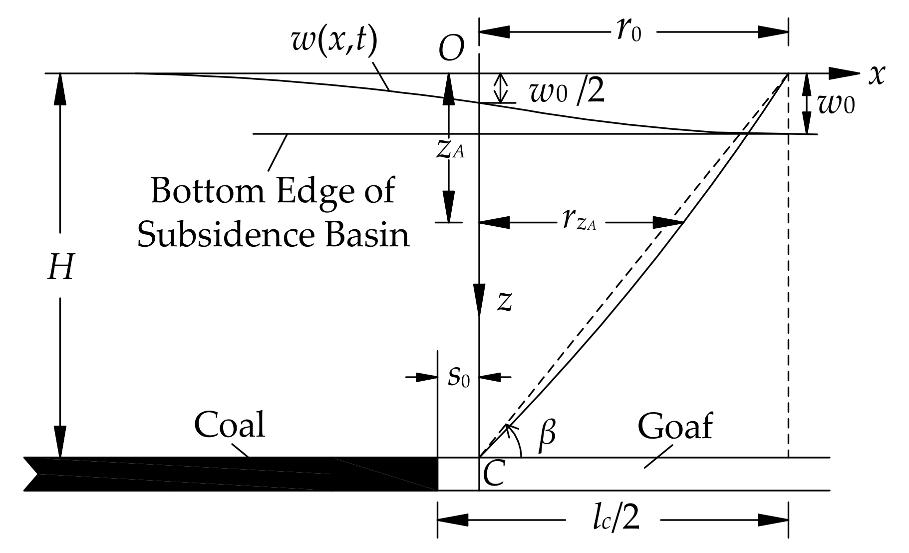
3.1. Calculation Methods

As early as the 1950s, the stochastic medium theory was first introduced by the Polish scholar Litwiniszyn for the study of rock movement [13]. The method was further developed into a probability integral method by the Chinese scholar Liu et al. [14]. Until now, the probability integral method has been the most widely used method for predicting mining subsidence [15,16,17]. The above prediction methods can only predict the ultimate deformation. However, with the mining of the working face, the stratum structures are inevitably subjected to dynamic deformations associated with the formation of a surface subsidence basin [18]. Currently, several models for predicting dynamic subsidence of the surface have been developed. The commonly used models are as follows: (1) Time function models were established by Knothe based on the Mitscherlich growth law [19], which has been widely used by many scholars around the world [20,21,22]. (2) Empirical models are based on the measurement of surface deformation [23,24]. (3) Models proposed by Peng and Luo and further improved by Luo are based on the normal distribution [18,25]. (4) Models deriving surface subsidence over time are based on the rheological characteristics of overburden strata [26]. Significantly, to determine the time function of a mining area’s subsidence, the corresponding parameters of the time function for the mining area must be accurately obtained. Considering that the above dynamic prediction models describe the movement of one point on the surface, the displacement of arbitrary points in the strata can be analyzed by using the probability integral method.

3.2. Mining Models

Based on the requirements of the problem, two ideal mining models —the parallel mining model (see Figure 2a) and the perpendicular mining model (see Figure 2b) —were established according to the relationship between the mining direction and the central line of the mining area. The mining area is completely mined, and the shaft is located on the central line. An independent coordinate system (ξCη) and a rectangular mining area (expressed by I and II, respectively) are arranged along the north and south sides of the central line. Each mining area is composed of n identical horizontal working faces and is mined in order from small to large according to the face number. To ensure the deflection direction of the shaft remains constant during the mining process, the same face numbers are selected for simultaneous mining. Assume that the strike length and the tendency length of the working face are l and s, respectively; the average advancing rate along the strike is v; the mining depth is H; and the minimum SPRP size is B. The coordinates on both sides of the central line are calculated according to the same-side coordinate system. For the sake of convenient analysis, the superscripts I and II were adopted to indicate the parameters of the corresponding mining area.

3.3. Model Solution

First, taking the parallel mining model as an example, when only mining area I is mined, a surface coordinate system is established and coincides with the horizontal projection of the face coordinate system shown in Figure 3. Assuming that the coordinates of unit E in the i-th working face relative to the face coordinate system are ( ξ E I , η E I , H I ), the coordinates of point A in the strata relative to the surface coordinate system are ( x A I , y A I , z A I ). The points A’ and E’ are the horizontal projections of A and E at the surface, respectively. Therefore, the ultimate subsidence displacement of point A caused by the mining of unit E can be calculated by the probability integral theory. In addition, considering the spatial and temporal characteristics of the mining surface subsidence, Knothe obtained a dynamic time function that is related only to the lithological time coefficient c by assuming that the subsidence velocity is directly proportional to the difference between the maximum subsidence value and the dynamic subsidence value at a certain moment. The dynamic time function T(t) can be expressed as
T t = 1 e c t .
Since any point in the subsidence strata has a similar movement law to the surface subsidence in time, under the same conditions, the movement laws of all points can be approximately expressed by the same time function. If ti denotes the time of the i-th working face from the initial mining to a certain time, it can be assumed to be an integral multiple of l/v to enable convenient calculations. Thus, the subsidence value of point A caused by mining the i-th working face at a certain moment can be derived as
w A i I = w 0 1 e c t i 0 l n i s n i + 1 s 1 r z A I 2 e π ( x A I ξ E I ) 2 + ( y A I η E I ) 2 r z A I 2 d η d ξ ,
where r z A I is the main influence radius at depth z A I .
The relationship between the main influence radius r z A I , the mining depth HI, and the main influence angle β is shown in Figure 4. Based on the probability integral theory, the expression of r z A I can be defined as
r z A I = r 0 H I z A I H I λ = H I tan β H I z A I H I λ ,
where r0 is the main influence radius at the surface and λ is a constant.
Based on the superposition principle of displacement, the subsidence value of point A caused by mining n working faces at the same moment can be written as
w A I = i = 1 n w 0 1 e c t i 0 l n i s n i + 1 s 1 r z A I 2 e π ( x A I ξ E I ) 2 + ( y A I η E I ) 2 r z A I 2 d η d ξ .
After integration, Equation (4) can be rewritten as
w A I = i = 1 n w 0 1 e c t i 4 erf k z I x A I erf k z I x A I l erf k z I y A I n i s erf k z I y A I n i + 1 s ,
where w0 is the maximum subsidence value of the strata when the working face is fully mined along the strike, and dip and erf represent the probability integral function, which can be defined by
w 0 = m q ,   erf k z I x A I = 2 π 0 k z I x A I e u 2 d u ,   k z I = π r z A I ,
where m and q are the mining thickness and the coefficient of stratal subsidence, respectively.
Suppose that s0 is the displacement of the inflection point and lc is the goaf critical size. According to the probability integral theory, lc = 2r0 + 2s0. It is well known that when the opening reaches its critical size along the strike and dip, the maximum value of the surface subsidence is approximately equal to 0.98w0 [27]. Therefore, when the working face is fully mined along only the strike, the maximum value of surface subsidence can be calculated to be equal to 0 . 98 w 0 erf [ π s / 2 r 0 ] . The advancing time is lc/v in the critical mining state, and when z = 0, the lithology time coefficient is equal to
c = v 2 r 0 + 2 s 0 ln 0.02 .
To study the horizontal movement of the strata and its deformation caused by coal mining, φ is defined as the angle rotated counterclockwise from the x axis in the positive direction to the specified direction at point A’. Thus, the inclination χ A I of point A in the φI direction can be expressed as the derivative of w A I in that direction with the unit length, which can be expressed as
χ A I = i = 1 n cos φ I w A I x + sin φ I w A I y .
In [28], the relationship between the horizontal displacement, u A I , and χ A I at point A is as follows:
u A I = i = 1 n b r z A I χ A I ,
where b is the horizontal movement factor.
Consequently, Equation (9) is the horizontal movement function of point A in the φI direction caused by mining of mining area I. The specific expression is shown in Equation (10):
u A I = i = 1 n b w 0 ( 1 e c t i ) 2 f 1 I g 2 I cos φ I + f 2 I g 1 I sin φ I ,
where
f 1 I = e k z I 2 x A I 2 e k z I 2 x A I l 2 , f 2 I = e k z I 2 y A I n i + 1 s 2 e k z I 2 y A I n i s 2 , g 1 I = erf k z I x A I erf k z I x A I l , g 2 I = erf k z I y A I n i s erf k z I y A I n i + 1 s .
When only mining area II is mined, assume that the coordinates of point A relative to the surface coordinate system in mining area II are ( x A II , y A II , z A II ). According to the face occurrence conditions in Figure 2, the following equations exist:
x A I = x A II , y A I = 2 n s y A II , z A I = z A II , H A I = H A II = H , r z A I = r z A II , k z A I = k z A II , φ I = φ II π .
Since mining areas I and II are distributed symmetrically, the vertical and horizontal movement functions of point A caused by mining of mining area II can be obtained by substituting Equation (11) into Equations (5) and (10).
Based on the calculations above, when mining areas I and II are mined simultaneously, the displacement of point A caused by mining is equal to
w A = w A I + w A II , u A = u A I + u A II .
Combined with the displacement solution process of point A under the parallel mining model, the displacement under the perpendicular mining model can be obtained by the same method. The result shows that the displacement expression of point A under the perpendicular model is the same as that of the parallel model. However, the difference is the relative coordinates of point A in both model coordinate systems and φ values in the same direction.

4. Solution of the Prediction Model for Shaft Deflection

Considering that the shaft has a large slenderness ratio and small lateral bending resistance, the displacement of the point on the shaft axis can be considered to be approximately equal to the soil at the same position. Therefore, assume that point A is the point on the shaft axis, and the displacement of point A can be regarded as that of the shaft at the same depth based on the assumption of a planar cross section. Combined with the location and the deflection direction of the shaft in Figure 2, when z is used to replace zA, the coordinates of point A can be expressed as follows: under the parallel mining model,
x A I = x A II = l + B , y A I = y A II = n s , z A I = z A II = z , φ I = φ II = π ;
under the perpendicular mining model,
x A I = x A II = l , y A I = y A II = n s + B , z A I = z A II = z , φ I = φ II = π / 2 .
The subscripts P and V represent the displacement parameters of the shaft under the parallel mining model and the perpendicular mining model, respectively. The displacement expression of the shaft for the two models can be obtained by substituting Equations (13) and (14) into Equation (12), respectively, which can be derived as
w P = i = 1 n w 0 1 e c t i 2 erf k z l + B erf k z B erf i k z s erf k z i 1 s ,
w V = erf k z l i = 1 n w 0 1 e c t i 2 erf k z i s + B erf k z i 1 s + B ,
u P = b w 0 e k z 2 l + B 2 e k z 2 B 2 i = 1 n ( 1 e c t i ) erf i k z s erf i 1 k z s ,
u V = b w 0 erf k z l i = 1 n ( 1 e c t i ) e k z 2 i 1 s + B 2 e k z 2 i s + B 2 .
Equations (15)–(18) are the dynamic prediction models for the shaft movement in the vertical and horizontal directions caused by multiface mining under the conditions of parallel mining and perpendicular mining. The above prediction parameters should be obtained based on the inversion of the measured data. For those parameters that cannot be inverted, the empirical values can be obtained by referring to [2].

5. Size Design of SPRP in Thick Soil and Thin Rock Strata

5.1. Parameters Solution

The Guotun Coal Mine, which has a production capacity of 2.4 Mt/y, is located in the middle of the Juye Coalfield in Shandong Province. The coal is mined by the longwall caving method. The dip angle of the coal seam is generally 5°–8°, which is a nearly horizontal coal seam. The mined face layout of the first mining area as of August 2017 is shown in Figure 5. It shows that the face layout is between the two mining models shown in Figure 2. Thus, an independent coordinate system was established for each working face and coincided with the horizontal projection of the corresponding surface coordinate system; the calculation process of the shaft deflection in the Guotun Coal Mine was consistent with the above. Considering that the vertical displacement of the shaft caused by mining has little influence on lining safety and hoisting safety, it was not necessary to analyze this. When the horizontal displacement of the shaft in the Guotun Coal Mine is represented by uG, then its expression can be calculated as
u G = i = 1 n b w 0 i ( 1 e c i t i ) 2 f 1 i g 2 i cos φ i + f 2 i g 1 i sin φ i ,
where w0i is the maximum subsidence value of the strata when the i-th working face is fully mined, ci is the lithological time coefficient of the i-th working face, and φi is the value of φ relative to the i-th surface coordinate system:
f 1 i x i , z i = e k z i 2 x i 2 e k i 2 x i l i 2 , f 2 i y i , z i = e k z i 2 y i 2 e k i 2 y i s i 2 , g 1 i x i , z i = erf k z i x i erf k z i x i l i , g 2 i y i , z i = erf k z i y i erf k z i y i s i , k z i = π tan β H i H i H i z i λ ,
where xi, yi, and zi are the coordinates of the shaft relative to the i-th surface coordinate system, respectively, and li, si, and Hi are the mining length, mining width, and mining depth of the i-th working face, respectively. The specific parameter values are shown in Table 3.
In this paper, the relevant prediction parameters in deep soil strata were solved based on the main shaft deflection of the Guotun Coal Mine. The prediction parameters were as follows: According to a research report [29], q = 1.0; in light of the criterion in [2], s0i = 0; the other parameters were obtained by inverting the measured data. First, according to the westward deflection values of the main shaft in June 2015 (see Figure 6), the inversion curve of the horizontal displacement in that direction was obtained (see curve I in Figure 6), which was basically consistent with the measured values and was suitable for Equation (19). The same parameters were then used to calculate the southward horizontal displacement (see curve II in Figure 6). The average difference between the calculated and measured values in the soil section was only 7 mm, which was less than the measurement error (8 mm). Accordingly, the prediction model could clearly invert the horizontal displacement at different shaft depths, and the reverse result showed high precision. Based on the known inversion prediction parameters, the horizontal displacement of the main shaft at different depths in 2015 (see curve I in Figure 7) and 2017 (see curve II in Figure 7) were calculated to further verify the reliability of the prediction effect. The results showed that the two theoretical values of the main shaft were largely consistent with the measured values at different depths. The prediction results were highly reliable. Based on the inversion results calculated above, the prediction parameters were λ = 0.7, b = 0.67, and tanβ = 0.51.

5.2. Influence of the Mining Model on Shaft Deflection

5.2.1. Analysis Process

Since the ideal mining models are mined more fully than the Guotun Coal Mine, the SPRP size calculated by the former models is more reliable. Therefore, referring to the parameters in Table 2, the model parameters that are suitable for thick soil and thin rock strata were selected as follows: H = 800 m, l = 1600 m, s = 200 m, v = 1200 m/y, m = 3 m, λ = 0.7, q = 1, s0 = 0, b = 0.67, and tanβ = 0.51. When B took different values, substituting the parameters into Equations (17) and (18), respectively, the relationship between the horizontal displacement of the shaft u and the number of working face n under the two mining models could be obtained. When n took different values, the horizontal displacement curves could be calculated, as shown in Figure 8, Figure 9, Figure 10 and Figure 11. The results showed that the mining had little effect on the bedrock section of the shaft and the deflection displacement at the shaft head was the largest, expressed by um. To more clearly show the influence of the different mining models on the shaft deflection, the variation curves of um with the mining time were obtained, as shown in Figure 12, and the difference of um between the two models with n was calculated, as shown in Figure 13.

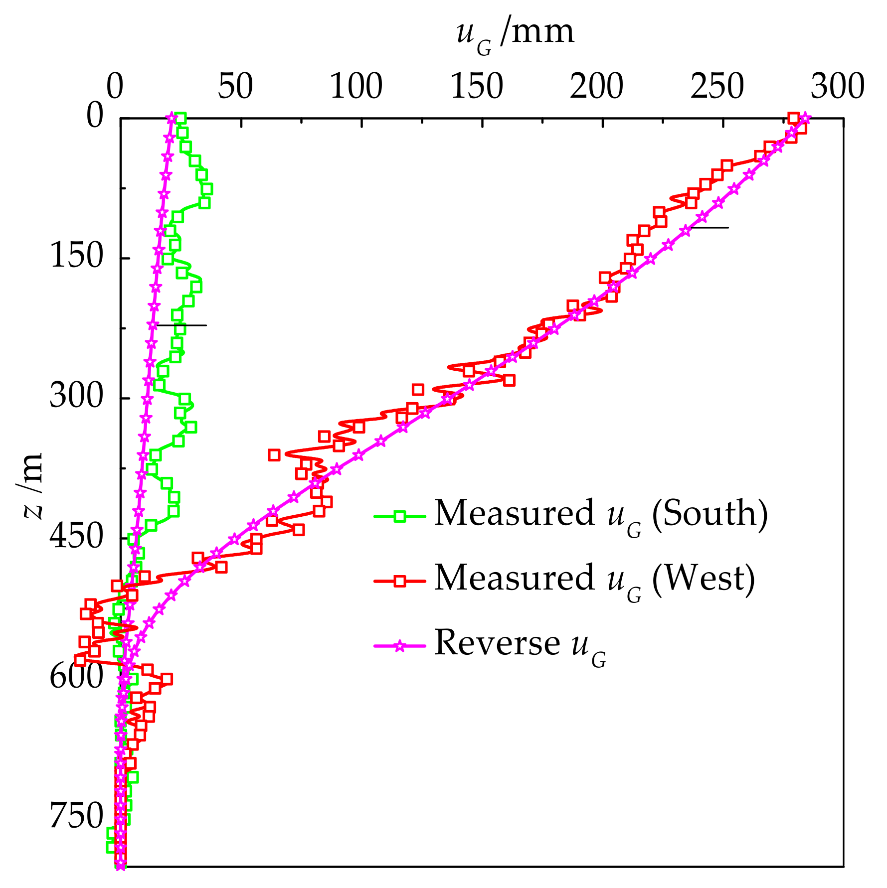
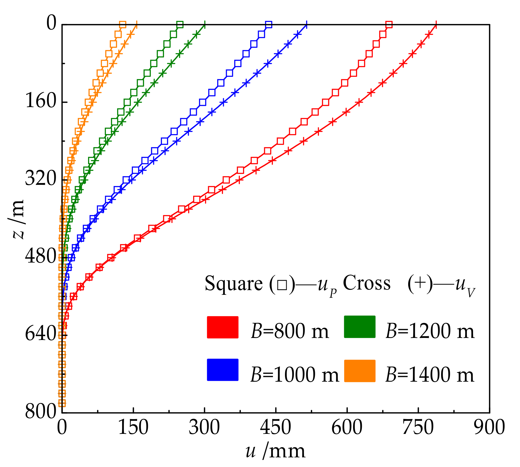
5.2.2. Calculation Results

As seen in Figure 8, Figure 9, Figure 10, Figure 11, Figure 12, Figure 13, when n < l / s , the horizontal displacement of the shaft under the perpendicular mining model was greater than that of the parallel mining model, and the displacement difference of the shaft head increased first and then decreased with the mining time; when n = l/s = 8, the horizontal displacement of the shaft under the two mining models was basically the same; when n > l / s , the horizontal displacement of the shaft was basically unchanged, indicating that the mining area had reached a state of full mining. Considering that the premature deflection is against the shaft safety, compared with the parallel mining model, the perpendicular mining model will cause greater horizontal displacement of the shaft at the initial stage of mining. Thus, the parallel mining model is superior to the perpendicular mining model.

5.3. The SPRP Designed by the Prediction Model

For a shaft constructed by the freezing method, deflection acceptance for each stage height needs to be carried out during the process of excavation and construction [30], so the deflection rate of the constructed shaft is approximately equal to 0. Therefore, when the opening reached its critical size (n = 8), the values of um under different values of B could be calculated based on the horizontal mining model, as shown in Figure 14.
As shown in Figure 14, with sufficient mining, the horizontal displacement value of the main shaft head in the Guotun Coal Mine was approximately 774 mm; um was the nonlinear negative correlation with B, and the fit expression was derived as
u m = 1970 e B 3.707 883.9 2 .
Therefore, for the Guotun Coal Mine or others with similar mining geological conditions, the SPRPs under different shaft head displacements can be obtained by the inverse calculation of Equation (20).

5.4. The SPRP Designed by Movement Angle

5.4.1. Solution of Theoretical Soil Movement Angle

When the shaft is located at the industrial square, its SPRP size is equal to the square protection rock pillar size plus the distance from the shaft to the industrial square boundary. It is known that the main shaft is 140 m away from the industrial square boundary, the width of the enclosure belt is 20 m, and the mining depth under the mining model is 800 m. The soil strata in the first mining area are divided into the Quaternary System and the Neogene System, which have maximum thicknesses of 149.75 and 504.45 m, respectively. According to the actual movement angles in the Guotun Coal Mine, when the SPRP size was equal to 858 m, the average thickness of the soil strata under the mining model was calculated to be 640 m, which corresponded to the actual situation. Since the mining had little influence on the bedrock section of the shaft, the rock movement angle was still equal to 70°. Therefore, assume the angle that is suitable for the design of the SPRP in deep soil strata and, similar to the soil movement angle, is defined as the theoretical soil movement angle, which is expressed by αs. According to the design requirements in the criterion [2], the main SPRP size was calculated by the parallel mining model as follows:
B = 640 tan α s + 160 tan 70 ° + 160 .
Substituting Equation (21) into Equation (20), the expression of αs can be written as
α s = arctan 2.98 / 4.12 ln 1970 u m 1 .
Based on Equation (22), the relationship between the horizontal displacement of the main shaft head um and the theoretical soil movement angle αs was obtained as shown in Figure 15.

5.4.2. Analysis Results

As shown in Figure 15, when the value of the theoretical movement angle for the Guotun Coal Mine was 77.8% and 57.8% of the actual movement angle (i.e., 45°), the horizontal displacement of the main shaft head was reduced by about 50% and 87%, respectively. This indicates that the shaft deflection can be effectively attenuated by appropriately reducing the soil movement angle used to design the SPRP in thick soil and thin rock strata.

6. Conclusions

Based on the probability integral method and the Knothe time function, a dynamic prediction model that can describe the horizontal movement of a shaft was established. For the main shaft deflection in the Guotun Coal Mine, a back analysis was adopted to calculate the prediction parameters that were suitable for the deep soil strata. By studying the relationship between the deflection displacement of the shaft and the SPRP, the following conclusions were obtained:
(1)
With full mining, the final displacements of the shaft under the two ideal mining models are equal, while the parallel mining model is superior at the initial stage of mining. The horizontal displacement of the shaft head has a nonlinear negative correlation with the SPRP, and the pillar size in thick soil and thin rock strata calculated by the parallel mining model is more reasonable.
(2)
Combined with the specification design method of the SPRP, the shaft deflection can be effectively attenuated by appropriately reducing the soil movement angle. For the Guotun Coal Mine, when the soil movement angle was 57.8% of the actual value, the horizontal displacement of the main shaft head was reduced by 87%.
(3)
According to the current production situation of the Guotun Coal Mine, filling mining is recommended for the coal seam around the shaft; for similar newly built shafts, symmetrical or filling mining should be adopted as much as possible according to the actual situation, and lining structures that can adapt to certain bending deformations should be selected. In addition, the inside of the freezing shaft should be constructed to be large on the top and small on the bottom, which is similar to that of the drilling shaft.

Author Contributions

All the authors contributed to this paper. J.H. prepared and completed the original draft; J.Z. and C.H. provided theoretical and methodological guidance in the research process; W.Y. managed the entire writing process and edited the manuscript as the project administrator

Funding

This research was supported by the National Key Research and Development Program of China (Grant No. 2016YFC0600904).

Acknowledgments

The authors would like to thank Guotun Coal Mine, Shandong University of Science and Technology, and China Coal Technology & Engineering Group Nanjing Design and Research Institute for their valuable data and technical support, as well as the editor and reviewers for their contributions to the paper.

Conflicts of Interest

The authors declare no conflicts of interests.

References

  1. Kratzsch, H. Mining subsidence engineering. Environ. Geol. Water Sci. 1986, 8, 133. [Google Scholar] [CrossRef]
  2. State Bureau of Coal Industry. Criterion for Coal Pillars and Coal Mining in Buildings, Water Bodies, Railways and Main Shafts; Coal Industry Press: Beijing, China, 2017; pp. 42–44. [Google Scholar]
  3. Zhang, R.L.; He, G.W.; Li, Z. Mining Engineering Design Manual (PartI); Coal Industry Press: Beijing, China, 2003; pp. 325–342. [Google Scholar]
  4. Zeenke, M.; Feng, K.P. Determination of the shape and size of shaft protection pillar in Ostrava—Karvin Coal Mine. Hebei Coal 1986, 3, 59–62. [Google Scholar]
  5. Haupt, W.; Schobel, F.; Sroka, A.; Feng, K.P. Determination of protection coal pillar and its size. Mine Surv. 1985, 2, 39–50. [Google Scholar]
  6. Kratzsch, H. Measures to Reduce Mining Damage Mining Subsidence Engineering; Springer: Berlin/Heidelberg, Germany, 1983. [Google Scholar]
  7. Sroka, A.; Dzegniuk, B.; Niedojadlo, Z. The Bases of Dimensioning and the Exploitation of Shaft Safety Pillars; School of Underground Minig/Szkola Eksploatacji Podziemnej: Krakow, Poland 2003. [Google Scholar]
  8. Wei, F.Y.; Chen, J.J.; Zou, Y.F. Influence factors and change law of protection coal pillars left. Coal Sci. Techno. 2006, 34, 85–87. [Google Scholar]
  9. Wei, F.Y.; Chen, J.J.; Zou, Y.F. Analytical model of protective coal pillar design for vertical section method. J. China Coal Soc. 2008, 33, 256–258. [Google Scholar]
  10. He, W.L.; Kang, J.R. Laws of ground movement and deformation in mountainous areas. J. China Coal Soc. 1992, 17, 1–15. [Google Scholar]
  11. Chen, S. A New Method for Numerical Analysis of Strata and Surface Movement; China University of Mining and Technology Press: Xuzhou, China, 1998; pp. 47–54. [Google Scholar]
  12. Cheng, X.L.; Liu, S.G.; Zhang, H.X. Technical Summary of Monitoring Project of Main and Auxiliary Shaft, Derrick, Head Sheave and Winch in Guotun Coal Mine; Research Report, Shandong Science and Technology University Technology Development Company: Qingdao, China, 2018. [Google Scholar]
  13. Litwiniszyn, J. Application of the equation of stochastic processes to mechanics of loose bodies. Arch. Mech. 1956, 8, 393–411. [Google Scholar]
  14. Liu, B.C.; Liao, G.H. The Law of Surface Movement in Coal Mine; China Architecture & Building Press: Beijing, China, 1965. [Google Scholar]
  15. Guo, W.B.; Deng, K.Z.; Zou, Y.F. Artificial neural network model for predicting parameters of probability-integral method. J. China Univ. Min. Technol. 2004, 33, 322–326. [Google Scholar]
  16. Zhang, H.; Wang, Y.J.; Li, Y.F. SVM model for estimating the parameters of the probability-integral method of predicting mining subsidence. Min. Sci. Technol. 2009, 19, 385–388. [Google Scholar] [CrossRef]
  17. Fan, H.D.; Gu, W.; Qin, Y.; Xue, J.Q.; Chen, B.Q. A model for extracting large deformation mining subsidence using D-InSAR technique and probability integral method. Trans. Nonferr. Metal. Soc. 2014, 24, 1242–1247. [Google Scholar] [CrossRef]
  18. Peng, S.S. Surface Subsidence Engineering; SME: New York, NY, USA, 1992. [Google Scholar]
  19. Knothe, S. Effect of time on formation of basin subsidence. Arch. Min. Steel Ind. 1953, 1, 1–7. [Google Scholar]
  20. Hu, Q.F.; Cui, X.M.; Wang, G.; Wang, M.R. Key technology of predicting dynamic surface subsidence based on Knothe time function. J. Softw. 2011, 6, 1273–1280. [Google Scholar] [CrossRef]
  21. Polanin, P. Application of two parameter groups of the Knothe–Budryk theory in subsidence prediction. J. Sustain. Min. 2015, 14, 67–75. [Google Scholar] [CrossRef]
  22. Zhu, X.J.; Guo, G.L.; Zha, J.F.; Chen, T.; Fang, Q.; Yang, X.Y. Surface dynamic subsidence prediction model of solid backfill mining. Environ. Earth Sci. 2016, 75, 1007. [Google Scholar] [CrossRef]
  23. Deng, K.Z.; Wang, J.Z.; Xing, A.S. On predicting the surface subsidence velocity in undermining process. J. China Univ. Min. Technol. 1983, 4, 68–79. [Google Scholar]
  24. Yu, X.Y.; Dang, T.H.; Pan, H.Y.; Wu, J.K. Theological characteristics of surface dynamic subsidence by mining. J. Xi’an Univ. Sci. Technol. 2003, 2, 131–134. [Google Scholar]
  25. Luo, Y. An Integrated Computer Model for Predicting Surface Subsidence due to Underground Coal Mining (CISPM). Ph.D. Thesis, Department of Mining Engineering, West Virginia University, Morgantown, WV, USA, 1989. [Google Scholar]
  26. Djamaluddin, I.; Mitani, Y.; Esaki, T. Evaluation of ground movement and damage to structures from Chinese coal mining using a new GIS couping model. Int. J. Rock Mech. Min. Sci. 2011, 48, 380–393. [Google Scholar] [CrossRef]
  27. Hu, Q.F.; Deng, X.B.; Feng, R.M.; Li, C.Y.; Wang, X.J.; Jiang, T. Model for calculating the parameter of the Knothe time function based on angle of full subsidence. Int. J. Rock Mech. Min. Sci. 2015, 19–26. [Google Scholar] [CrossRef]
  28. He, G.Q.; Yang, L.; Ling, G.D.; Jia, C.F.; Hong, D. Mining Subsidence Theory; China University of Mining and Technology Press: Xuzhou, China, 1991; pp. 118–157, 342–344. [Google Scholar]
  29. Shandong Luneng Group Heze Coal Power Development Co. LTD.; Shandong University of Science and Technology. Research Report on Surface Movement and Deformation Law of 1308 Working Face in Guotun Coal Mine; Shandong University: Qingdao, China, 2012. [Google Scholar]
  30. Ministry of Coal Industry. Code for Construction and Acceptance of Mine Shaft and Roadway Works (GBJ213–79); Coal Industry Press: Beijing, China, 1983. [Google Scholar]
Figure 1. The ratio of soil thickness to total depth of the shaft.
Energies 12 02553 g001
Figure 2. Schematic diagram of the mining models.
Energies 12 02553 g002
Figure 3. The spatial coordinate system: (1) earth’s surface; (2) mining of a coal seam.
Energies 12 02553 g003
Figure 4. Significance of subsidence parameters caused by mining.
Energies 12 02553 g004
Figure 5. The mine working face layout.
Energies 12 02553 g005
Figure 6. Measured and reverse values of the horizontal displacement (2015.6).
Energies 12 02553 g006
Figure 7. Measured and predictive values of the horizontal displacement.
Energies 12 02553 g007
Figure 8. The shaft horizontal displacement curve (n = 4).
Energies 12 02553 g008
Figure 9. The shaft horizontal displacement curve (n = 6).
Energies 12 02553 g009
Figure 10. The shaft horizontal displacement curve (n = 8).
Energies 12 02553 g010
Figure 11. The shaft horizontal displacement curve (n = 10).
Energies 12 02553 g011
Figure 12. The variation curves of um with the mining time.
Energies 12 02553 g012
Figure 13. Difference of um between the two models with n.
Energies 12 02553 g013
Figure 14. Values of um under different values of B.
Energies 12 02553 g014
Figure 15. The relationship between um and αs.
Energies 12 02553 g015
Table 1. The movement angles of some mine areas in China.
Name of MineMining Depth (m)Movement Angles (°)
Rock StrataSoil Strata
DownhillUphillStrikeDip
Jiaohe35–11075‒0.8α7575 45
Xuzhou90–14075−0.82α;
70 −0.72α
75;
70
75;
70
45;
36
Shuangyashan30–22075 − 0.3α6870 45
Pingyuan100–330727268 55
Huainan<18075 − 0.65α;
53 − 0.1α
757555;
75 − 0.65α;
53 − 0.1α
40–45
Fengfeng<26073 − 0.6α7373 58
Weizhou<31073 − 0.6α7373 45–55
Fuxin<40073; 83 − 0.9α7572 40–50
Fushun<54059 − 0.2α6265 45
Kailuan<60072 − 0.67α (≥30)35–7270 35–45
Zaozhuang<60086.6 − α7676 45
Changzhi<60068 − 7371–7471–74 55–66
Jining>60065 − 757575 40–45
Juye>60075 ‒ 0.3α70–7570–75 40–45
Note: α is the dip angle of coal seam.
Table 2. Design parameters and deflective situations of shafts in the Guotun Coal Mine.
ParametersMain ShaftAuxiliary Shaft
Shaft depth (m)853882
Soil thickness (m)587.4582.7
Date Maximum   deflection   value   ( mm ) Azimuth   angle   ( ° )
July 2015 349 95 322 77
August 2017 359 79 318 75
Note: The maximum deflection value in the table refers to the measured displacement of the main (auxiliary) shaft head relative to the shaft depth at the intersection of the soil and rock layers [12].
Table 3. Calculation parameters of the working faces and main shaft coordinates.
iFace
Number
si (m)li (m)mi (m)Hi (m)CoordinatesNorthStart DateEnd Date
xi (m)yi (m)φi (°)(Year. Month)(Year. Month)
113022004902.8780810950178January 2010July 2010
213041508703.27707851378202August 2010March 2011
3130122717683.178402525692335November 2010January 2013
413081578883.0874012801385168July 2011March 2012
5130323016752.998452535937335June 2012June 2015
1695August 2015
613101907903.27307962065198December 2012August 2013
713052459853.4182025311194335September 2013June 2015
1250August 2016
81312-113064037306552313208March 2014June 2014
91312-2130134037359342137188July 2014May 2015
1013061104602.87459421913208July 2015December 2015
11130724021003.377028361445335April 2016August 2017
1213151103603.174010901605169July 2016September 2016
1313111362663.17852060349105April 2017July 2017
Note: 1312-1 and 1312-2 represent the two parts divided by the 1312 working face at the turning point.

