Abstract
The stability of a deep composite roof is a powerful guarantee for the safe and efficient production of a coal mine. The coal–rock combination, the single rock or coal bodies have different bearing capacity; thus, we can accurately obtain the deformation field evolution and failure mechanisms of the combination, which is useful in the deformation control of a composite roof. In this study, based on the digital speckle correlation method (DSCM), a uniaxial compression test was applied to coal–rock combinations with different height ratios. The results revealed that the compressive strength, elastic modulus, and secant modulus of the combination gradually decreased, while the decreasing amplitude weakened with the increase of coal height. Additionally, the strain field map of the combination had different characteristics in different stages. As the height of the coal body continuously increased, the gradient of the strain cloud and the area of local strain increase moved upwards. Moreover, the cracks caused by the failure of the coal body in the combination triggered the failure of the rock body. According to the test results, two principles are proposed for the deformation control of the composite roof, and are expected to be useful in applications for the similar geological conditions.
1. Introduction
With the continuous decrease of China’s coal resources, the exploitation of deep coal is unavoidable. However, deep mining has problems such as high temperature and high pressure, and is also challenged by the complexity of the geological environment [1,2,3]. With regard to roadway engineering, roadways with composite roofs will become increasingly more common in deep mines [4,5,6,7]. Moreover, because the coal–rock composite roof is the most common type, the investigation of the deformation field evolution and failure mechanisms of combinations with different coal–rock height ratios are significant as a reference for controlling the deformation of the composite roof.
For many years, studies have used laboratory experiments, numerical software, and theoretical modelling to investigate the mechanical properties and failure mechanism of the coal–rock combinations with regard to the strength, energy, and combined mode [8,9,10,11,12,13,14,15,16,17,18,19,20,21]. Chen [8] conducted a uniaxial compression test for a sandstone-coal structure with different coal–rock heights to investigate the mechanical properties and progressive failure mechanism based on acoustic emission detection technology. Dou et al. [9,10,11] and Tan [12] investigated the impact tendency of a coal–rock combination, and found that the coal–rock height ratio and the rock body strength had great impact on the mining tremor. Liu [13] investigated the effect of rock strength on the mechanical behavior and acoustic emission characteristics of a coal–rock combination. Zuo [14,15,16] conducted uniaxial and triaxial compression tests with a coal–rock combination, and used the acoustic emission detection method to systematically investigate the mechanical properties and failure characteristics of a coal–rock combination during loading and unloading cycles. In addidtion fro investigating the properties of such a combination by the numerical simulations and theoretical analyses. Li [17] used the FLAC numerical software to investigate the impact characteristics of different coal–rock height ratios and angles. Zhao [18] used the realistic failure process analysis (RFPA) numerical software to investigate the impact tendency of a coal–rock combination with different roof strength, thickness, and homogeneity. Moreover, Lin [19] used RFPA to analyze the failure process and fracture evolution mechanism of a rock-rock combination with different lithologies. Guo [20] conducted a numerical simulation study on four roof-coal combinations with different dip angles. Then, the compressive strength and failure mechanism of the coal–rock combination were analyzed under axial and triaxial compression conditions. The influence of the interface dip angle on the overall deformation and failure of the coal–rock combination was also analyzed. Zhao [21] derived the compression-shear strength criterion of the coal–rock combination, which considered the interface effect based on the strain energy equivalency principle. The laboratory test, numerical analysis, and theoretical modeling results revealed that there existed great difference between the coal–rock combination and the single coal or rock body. Moreover, the loading mode, combination mode, coal–rock height ratio, and contact surface dip angle exerted great influence on the mechanical behavior.
Existing studies have focused on the mechanical behavior and impact tendency of combinations. However, a combination with different coal–rock height ratios has been somewhat poorly investigated with regard to roof stability. Moreover, there is scarce literature regarding the evolution of the surface deformation field and the feedback of the crack propagation law and failure mechanisms. In this study, the haulage roadway (HR) 21205 of the Hulusu Coal Mine at the Ordos City Coal Mine Group was used as the engineering background to produce combination specimens with different coal–rock height ratios. The mechanical testing and simulation (MTS) universal testing machine was used to carry out a uniaxial loading test. In conjunction with the combination’s full-field strain and displacement cloud, as obtained by the DSCM, the deformation field evolution and failure mechanism of combinations with different coal–rock height ratios were revealed. Finally, technical considerations are proposed to control a composite roof.
2. Materials and Methods
2.1. Site Description
The coal specimens and rock specimens were taken from the roof of the HR 21205 of the Hulusu Coal Mine, Ordos City, China (Figure 1a). The rock specimen had argillaceous sandstone lithology. Figure 1b shows the schematic diagram of the test roadway. In this working face, the coal layer has a thickness of 3.7 m, and is considered as a medium thickness coal layer. The immediate roof of the roadway consists of coal and muddy sandstone, and is therefore a composite roof structure. On-site observation revealed that the coal body is relatively hard; however, the joints and cracks inside it were relatively developed. Crack expansion can easily occur under the influence of mining stress. Figure 2 shows a microscopic view of the coal, and Figure 2a shows the smooth plane of the coal. Additionally, there are multiple layers on the surface. After local enlargement, fine cracks appear in the layers. Figure 2b shows the coal fracture location with an obvious transverse joint and many disordered cracks around it. Owing to the large number of cracks in the coal layer of the roof, the expansion does not only affect the stability of the coal layer, but can also affect the argillaceous sandstone above it, which reduces the stiffness of the roof. As shown in Figure 1, the structural unit of a composite roof was considered as the coal–rock combination. The deformation characteristics and failure mechanism of the coal–rock combination have important guiding significance in controlling the coal–rock composite roof.
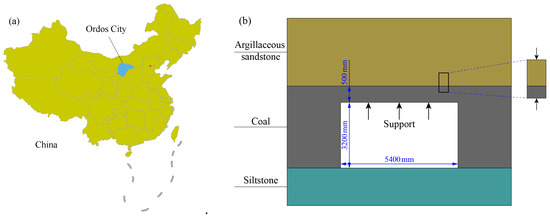
Figure 1.
Geographic location of Ordos City and schematic diagram of test roadway: (a) geographic location of Ordos City; (b) schematic diagram of test roadway.
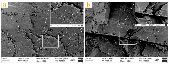
Figure 2.
Microscopic position of coal: (a) smooth position; (b) fracture position.
2.2. Specimen Preparation
The coring, cutting, and polishing of the coal and rock specimens were carried out on site using a drilling machine, cutting machine, and grinding machine, respectively. Then, specimens with D = 50 mm and different heights were processed. Additionally, it was required that the non-parallelism of the two specimen ends was no greater than 0.01 mm, and that the diameter deviation of the upper and lower ends was no greater than 0.02 mm. The height of the coal–rock specimen was processed according to Table 1. The coal–rock specimens with different heights were bonded to standard specimens using binder; the overall size was 50 mm × 100 mm. The combinations were categorized into seven types with the coal–rock height ratios of 0:1, 1:7, 1:3, 1:1, 3:1, 7:1, and 1:0, respectively. The combination specimen and the model are presented in Figure 3.

Table 1.
Lithology combination and coal–rock height ratio of specimen.
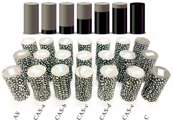
Figure 3.
Coal–rock combination specimen and model; the specimen was subjected to surface speckle treatment.
In the experiment, 21 coal–rock combination specimens were used. The height, mass, and density of the coal–rock combination specimens are listed in Table 2. These parameters were carefully investigated, and particular attention was paid to abnormal parameters in the analysis of experimental data because the variation of some parameters may result in a large deviation between the test results and the normal values.
Table 2.
Critical parameters of prepared specimens.
2.3. Test Equipment
The test equation is presented in Figure 4. The MTS electro-hydraulic servo universal test machine (model C64.106/1000 kN) was used for loading. The test machine mainly comprises the control system and loading system. During the test, the force loading mode was used and the loading rate was 200 N/s. The testing machine had the following characteristics: high stiffness six-column load frame configuration, servo-controlled hydraulic actuation system, and standard double test space. The maximum loading pressure was 1000 kN.
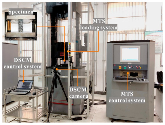
Figure 4.
Mechanical testing simulation (MTS) test system and digital speckle correlation method (DSC)M measurement system.
The test monitoring system is a measurement system based on DSCM, and mainly consisted of a hardware system responsible for image acquisition and a software system responsible for acquisition control and image processing analysis. The hardware system included a digital camera, supporting device, and speckle combing tool. Finally, the software system includes an image acquisition control system and a post-processing system.
2.4. Measurement Method and Principle
The DSCM is a method of obtaining the deformation field of the measured surface based on speckle image analysis. This method was initially proposed by Yamaguchi et al. in the early 1980s, and later developed to a mature deformation field through many studies [22,23]. The method has full field and non-contact characteristics, and easy implementation. Moreover, it has been successfully applied to deformation tests with materials such as rock. The basic principle of the DSCM is to match the geometric points on the digitized speckle image to different states of the object surface. Hence, the motion of the tracking point can obtain the deformation information of the object surface [24].
3. Results and Analyses
3.1. Test Results for Mechanical Properties
Figure 5 shows the average stress–strain curves for seven types of coal–rock combinations. The stress–strain curves obtained with different coal–rock height ratios are obviously different, and the compressive strength of the combination tended to decrease as the coal height increased. Because the coal–rock height ratio was 0:1, that is, there only existed a single argillaceous sandstone, the compressive strength was the largest, the peak intensity corresponded to the smallest strain, and the stress decreased after reaching the peak point. When the coal–rock height ratio reached 1:7 and 1:3, the compressive strength of the two combinations was similar, but much lower than that of the sandstone specimen only, and the corresponding strain value greatly increased. With a coal–rock height ratio of 1:7, the combination had a long-term loading process. After reaching the peak strength, the coal body was destroyed by deformation, and the rock body was loaded throughout this process. After the peak points of the two combinations, the stress was reduced in the arc-shaped. When the coal–rock height ratio was 1:1, the compressive strength of the specimen was greatly reduced, and the strain corresponding to the peak strength slightly increased. When the coal–rock height ratio was 3:1, 7:1, and 1:0, the compressive strength of these three combinations was similar. When the coal–rock height ratio was 1:1, the compressive strength slightly decreased, and the corresponding strain value remained essentially unchanged. According to the above analyses, the coal–rock height ratio of 1:1 was the turning point for the mechanical properties. When the height of the rock body exceeded that of the coal body, the mechanical properties of the combination tended toward those of the rock body. Otherwise, the mechanical properties of the combination tended toward those of the coal body.
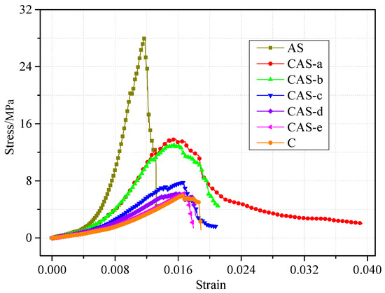
Figure 5.
Average strain–stress curves for different specimens.
The peak compressive strength, secant modulus, tangent modulus, and corresponding average values of seven combinations are listed in Table 3. The corresponding relationships between the peak compressive strength, secant modulus, and elastic modulus of the different combinations are shown in Figure 6. According to Table 3 and Figure 6, the peak compressive strength, secant modulus, and elastic modulus decreased as the height of the coal body increased. Moreover, the specimens with the coal–rock height ratios of 1:7, 1:3, 1:1, 3:1, 7:1, and 1:0 were much smaller than the specimens with a coal–rock height ratio of 0:1.
Table 3.
Mechanical properties of single coal, single rock, and structural specimens.
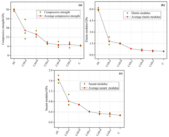
Figure 6.
Mechanical properties of combinations with different coal–rock height ratios: (a) compressive strength and average compressive strength; (b) elastic modulus and average elastic modulus; (c) secant modulus and average secant modulus.
3.2. Dynamic Stress and Strain Characteristics
Figure 7 shows the stress–strain characteristics of the coal–rock combination during the progressive failure. The curve represents the stress evolution with time, and can be divided into four phases: the compaction phase, elastic phase, yield phase, and post-peak phase. The typical composite samples were selected, and its strain field evolution in the compaction phase, elastic phase, yield phase, and post-peak phase was observed. The compressive strength law for combinations with different height ratio has been described above, thus, it will not be repeated in this section. The standard deviation of the compressive strength for a combination with a coal–rock height ratio of 0:1 and 1:0 was small, and the two curves were relatively consistent. Moreover, other combinations with the coal–rock height ratios of 1:7, 1:3, 1:1, 3:1, and 7:1 had a relatively large compressive strength standard deviation, and the compaction stage and elastic stage of each group were relatively similar. Moreover, the curves of the yield stage and post-peak stage were quite different, which is mainly attributed to the bearing performance difference caused by the different force locations in the combination.
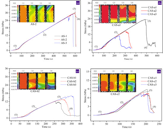
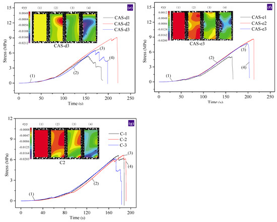
Figure 7.
Stress-strain characteristics of progressive failure for combination: (a) coal–rock height ratio of 0:1; (b) coal–rock height ratio of 1:7; (c) coal–rock height ratio of 1:3; (d) coal–rock height ratio of 1:1; (e) coal–rock height ratio of 3:1; (f) coal–rock height ratio of 7:1; (g) coal–rock height ratio of 1:0.
The strain fields of different combinations were obviously different. As shown in Figure 7, the strain field distribution can be divided into three stages: the uniform deformation stage, local deformation stage, and deformation failure stage. During the loading process, the compaction phase belongs to the uniform deformation phase of the strain field. The contour line of the strain field was relatively uniform, and the stress can be uniformly transmitted. The elastic phase and yielding phase during the loading process belong to the local deformation phase of the strain field. According to Figure 7a,g, the single rock-coal strain field was mainly distributed in the longitudinal direction, while the strain concentration occurred at the position of contact with the upper and lower ends. As shown in Figure 7b–f, there was a significant strain gradient in the strain field of the combination, and the strain value from the bottom to the top gradually decreased. In the combination, the strain value of the coal body was much larger than that of the rock body. As the height of the coal body increased, the strain gradient on the map moved upward, and the position of the coal body’s local strain concentration also moved upward. At the end of the local deformation phase, the fracture of the coal body significantly expanded. During the loading process, the post-peak stage belonged to the deformation stage and the failure stage of the strain field. Moreover, the area of local strain increase led to further strain concentration, which resulted in the destruction of the combination. The combination damage was concentrated in the coal body.
3.3. Evolution Law of Displacement Field
Figure 8 shows the cloud of the combination’s lateral displacement field evolution. The displacement field cloud had similar characteristics to the strain field map. In the pre-peak stages, namely stages (1) and (2), the contour direction of the displacement field was approximately perpendicular to the loading direction, and the local displacement did not increase (Figure 8a and Figure 7g).
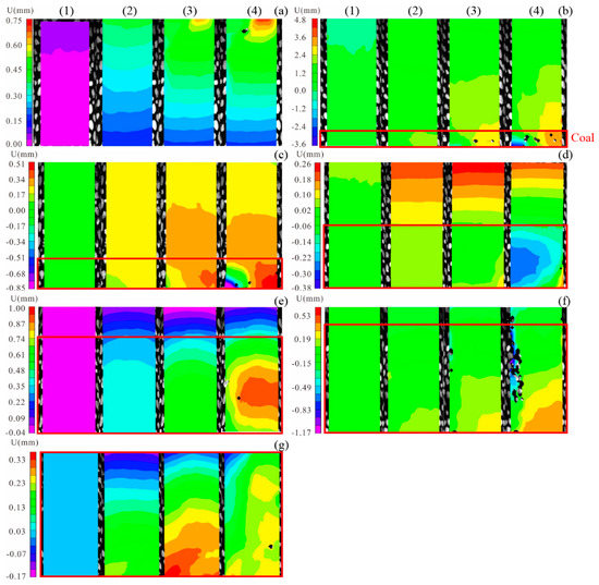
Figure 8.
Evolution cloud map of lateral displacement field for combination: (a) AS-2, (b) CAS-a1, (c) CAS-b2, (d) CAS-c2, (e) CAS-d3, (f) CAS-e3, (g) C-2; (1), (2), (3), and (4) are the compaction stage, elastic stage, yield stage, and post-peak stage, respectively. Coal is inside the red box, and rock is outside of the red box. The negative value in the ruler indicates the direction to the left, while the positive value indicates the direction to the right.
When the combination reached the peak load, namely stage (3), the surface deformation of the combination did no longer exhibit regular variation, while specimens AS-2, CAS-a1, CAS-b2, CAS-e3, and C-2 exhibited local sudden variation, and the appearance of the destruction point was imminent. According to Figure 8a, local deformation occurred in the upper part of the specimen, which indicates that the crack would first start to expand at this position, with an obvious end effect. According to Figure 8b,c,g, the surface displacement of the coal in the combination began to aggregate, and the displacement amount greatly increased; the destruction first started from the coal. According to Figure 8d,e, the combination maintained a uniform displacement gradient during the peak stage. Additionally, it is indicated that the displacement will suddenly change when the failure occurs. As can be seen in Figure 8f, the side of the coal body was spalled off. Moreover, it was found that the displacement field of the specimen did not exhibit an obvious separation at the coal–rock interface, while the displacement contour of the coal body evenly extended into the rock body. Therefore, the energy released by the failure of the coal body can exceed the minimum energy needed to rock body failure, and the rock body can be destroyed.
In the post-peak stage, namely stage (4), the combination was destroyed, while the failure location and displacement mutation position of stage (3) were essentially the same. As shown in the displacement cloud, it was found that the AS-2 specimen was destroyed at the end position, while the coal body of specimens CAS-a1 and CAS-b2 expanded and formed a local deformation zone on both sides of the combination. Moreover, the left and right stripping of the coal body occurred. Because the rock body exceeded the coal body, the rock body was still carried as the coal body was destroyed. For specimens CAS-c2 and CAS-d3, the area of increasing displacement was on one side of the coal body, and the cracks would be destroyed along this side. The displacement clouds of the CAS-e3 and C-2 specimens exhibit left-right differentiation. As the height of the coal body increased, the combination became prone to splitting failure.
3.4. Failure Patterns and Modes
Figure 9 shows the final failure pattern of the combination, when the tensile-shear failure of the combination occurred. The AS-3 specimen had many cracks running through the entire rock body. According to Section 3.2 and Section 3.3, the coal in the combination was destroyed first, and this caused the destruction of the entire specimen. According to failure pattern analysis, the combination failure mode was different. The coal–rock height ratio in the CAS-a1 specimen was 1:7, the coal height was extremely small, and the coal body was slowly extruded into a powder under pressure. The rock body formed a weak surface at the interface with a crack. The coal–rock height ratio of the CAS-b2 specimen was 1:3, the rock body was still the main carrier. The deformation generated during the loading process mainly came from the coal body. In the CAS-c3 specimen, the coal–rock height ratio was 1:1. Energy was released as the coal body destroyed, and this could have extended the cracks in the coal body to the rock mass. If the combined body did not undergo large deformation, the crack generated in the coal expanded into the rock body. Here, the rock body was destroyed, and the results revealed that the compressive strength of the combination was much smaller than that of specimens AS-3, CAS-a1, and CAS-b2. Specimens CAS-d3, CAS-e3, and C-2 had similar failure characteristics. The rock body was not the main bearing body, and did not destroy. The combination mainly exhibited coal characteristics, particularly with regard to the form of splitting failure.
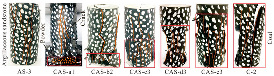
Figure 9.
Final failure pattern of partial combination specimen.
4. Discussions
More coal–rock composite roofs should be faced in deep roadways [25,26,27]. However, composite roof types with different heights often exhibit different deformation and failure characteristics. Therefore, it is very important to measure the deformation field evolution of the combination to clarify the deformation mechanism of a roadway with a composite roof.
The DSCM measurement system was used to observe the surface non-contact during the process of combined failure, because it can accurately reflect the deformation and damage of specimens. Figure 10a shows the principal strain direction field cloud of the AS-3 specimen in the post-peak failure stage. As can be seen, the principal stress direction had obvious left–right differentiation. Thus, it was assessed that the specimen underwent tension–shear failure. The cloud map obtained by the measurement system was validated by the entity diagram shown in Figure 10b. Compared with the traditional strain gauge, the DSCM measurement system can observe the fracture evolution process of an entire specimen subjected to an external load, which is an obvious advantage.
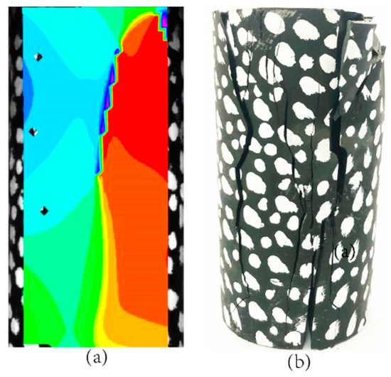
Figure 10.
Cloud map and photo in post-peak stage for AS-3 specimen: (a) principal strain direction field cloud; (b) final pattern of specimen after failure.
The rock specimen was argillaceous sandstone, and the average compressive strength was only 29.81 MPa, which is usually smaller than that of medium sandstone and fine sandstone. The energy released by the coal body can easily result in damage to the rock body, and the crack of the coal body can pass to the rock body through the coal–rock interface. Combined with the deformation field evolution of the coal–rock combination, the following two principles should be considered in the deformation control of a coal–rock composite roof:
(1) Maintain the integrity of the coal layer in the composite roof. The coal contains a large number of micro-cracks and joints, which are heterogeneous. Owing to the roadway excavation, the surrounding of the roof is subjected to bidirectional stress or unidirectional stress. If control is not exerted on time, the micro-cracks in the coal layer will expand, which can result in the destruction of the coal layer. Moreover, the cracks in the coal will extend into the rock layer and the entire composite roof will be damaged. Therefore, the composite roof should be controlled on time to maintain the integrity of coal in the composite roof after the roadway excavation.
(2) Ensure that there is no separation between the coal and rock layers. According to the strain field and displacement field clouds, under external loading, the coal body and the rock body always stick together before the failure of the coal body. Additionally, the stress is continuously transmitted into the coal body and rock body, and there is no strain and displacement discontinuity, which ensures the integrity of the combination. For a composite roof, strong support is required to form an overall structure, improve the strength and stiffness of the composite roof, and ensure the continuous transmission of stress and the safety of the roadway.
5. Conclusions
- (1)
- The compressive strength of the coal–rock combination is directly related to the height of the coal body and rock body. When the rock body is higher than the coal body, the strength of the combination is biased toward the strength of the rock body. Owing to the existence of coal, the strength of various combination specimens is between that of the single rock body and that of the coal body. The compressive strength, elasticity modulus, and tangent modulus of the coal–rock combination gradually decrease as the height of the coal body increases, and the reduction range decreases.
- (2)
- The strain field map of the progressive failure process of the coal–rock combination can be divided into three stages: the uniform deformation stage, local deformation stage, and deformation failure stage. The compaction stage and the elastic stage in the stress-strain curve belong to the uniform deformation stage in the strain field map. Moreover, the contours in the cloud map are relatively uniform. The yield stage in the stress-strain curve belongs to the local deformation stage in the strain field map, where the combination has a significant strain concentration; the strain-increasing area is located in the coal. The post-peak stage in the stress-strain curve belongs to the deformation failure phase in the strain field map. Additionally, the strain is further increasing and the specimen is destroyed.
- (3)
- The final failure mode of the combination is integral tensile and shear failure. When the height of the rock body is greater than the height of the coal body (coal–rock height ratio ≤ 1), the coal body is destroyed but the rock body continues to bear the load. Finally, the rock body is also destroyed. With a coal–rock height ratio of 1:1, the cracks in the coal will extend into the rock body through the interface, which can lead to the overall destruction of the combination.
- (4)
- Two principles are proposed for controlling the deformation of a coal–rock composite roof: maintaining the integrity of the coal layer in the composite roof, and ensuring that there is no separation between the coal and rock layers.
Author Contributions
Data curation, Z.X.; formal analysis, Z.X., N.Z., F.M., C.H. and Y.A.; funding acquisition, N.Z.; investigation, Z.X. and Y.A.; project administration, N.Z. and R.Z.; writing—original draft, Z.X.; writing—review and editing, Z.X. and F.M.
Funding
This work was financially supported by the Fundamental Research Funds for the Central Universities (2017CXNL01).
Acknowledgments
The authors are grateful to the staff at the Hulusu Coal Mine for their assistance during the field measurements. We thank Liwen Bianji, Edanz Editing China (www.liwenbianji.cn/ac), for editing the English text of a draft of this manuscript.
Conflicts of Interest
The authors declare no conflict of interest.
References
- Xie, H.P.; Gao, F.; Ju, Y. Research and development of rock mechanics in deep ground engineering. Chin. J. Rock Mech. Eng. 2015, 34, 2161–2178. [Google Scholar]
- Zhang, N.; Li, Y.; Zheng, X.G.; Xue, F. The present situation and technical challenge of deep coal resources exploitation. In Proceedings of the National Symposium on Mining Technology of Kilometer Deep Shaft in Coal Mine; 2013; Volume 7, p. 25. Available online: http://cpfd.cnki.com.cn/Article/CPFDTOTAL-ZGMG201307001002 (accessed on 12 June 2019).
- Wang, Z.Y.; Dou, L.M.; Wang, G.F. Mechanism Analysis of Roadway Rockbursts Induced by Dynamic Mining Loading and Its Application. Energies 2018, 11, 2313. [Google Scholar] [CrossRef]
- Young, M.; Walton, G.; Holley, E. Investigation of factors influencing roof stability at a Western U.S. longwall coal mine. Int. J. Min. Sci. Technol. 2019, 29, 139–143. [Google Scholar] [CrossRef]
- Ren, Y.; Feng, G.; Wang, P.; Guo, J.; Luo, Y.; Qian, R.; Sun, Q.; Li, S.; Yan, Y. Vertical Stress and Deformation Characteristics of Roadside Backfilling Body in Gob-Side Entry for Thick Coal Seams with Different Pre-Split Angles. Energies 2019, 12, 1316. [Google Scholar] [CrossRef]
- Ma, X.G.; He, M.C.; Wang, J.; Gao, Y.; Zhu, D.; Liu, Y. Mine Strata Pressure Characteristics and Mechanisms in Gob-Side Entry Retention by Roof Cutting under Medium-Thick Coal Seam and Compound Roof Conditions. Energies 2018, 11, 2539. [Google Scholar] [CrossRef]
- Zhang, H.Q.; Han, L.S.; Qi, Y.J.; Zhang, Y.F. Stability control mechanism and integral supporting technology of roadways with thick compound roof strata. In Proceedings of the 2nd ISRM International Young Scholars’ Symposium on Rock Mechanics, Beijing, China, 14–16 October 2011; pp. 709–712. [Google Scholar]
- Chen, S.J.; Yin, D.W.; Zhang, B.L. Mechanical characteristics and progressive failure mechanism of roof-coal pillar structure, Chin. J. Rock Mech. Eng. 2017, 7, 33–43. [Google Scholar]
- Dou, L.M.; Lu, C.P.; Mu, Z.L.; Zhang, X.T.; Li, Z.H. Rock burst tendency of coal-rock combinations specimen. J. Min. Safe Eng. 2006, 23, 43–46. [Google Scholar]
- Cao, A.Y.; Dou, L.M.; Luo, X.; Zheng, Y.D.; Huang, J.L.; Andrew, K. Seismic effort of blasting wave transmitted in coal-rock mass associated with mining operation. J. Cent. South Univ. 2012, 19, 2604–2610. [Google Scholar] [CrossRef]
- Lu, C.P.; Dou, L.M.; Wu, X.R.; Mu, Z.L.; Chen, G.X. Experimental and empirical research on frequency spectrum evolvement rule of rockburst precursory microseismic signals of coal-rock. Chin. J. Rock Mech. Eng. 2008, 27, 519–525. [Google Scholar]
- Tan, Y.L.; Yu, F.H.; Ning, J.G.; Zhao, T.B. Design and construction of entry retaining wall along a gob side under hard roof stratum. Int. J. Rock Mech. Min. Sci. 2015, 77, 115–121. [Google Scholar] [CrossRef]
- Liu, J.; Wang, E.Y.; Song, D.Z.; Yang, S.L.; Niu, Y. Effects of rock strength on mechanical behavior and acoustic emission characteristics of specimens composed of coal and rock. J. China Coal Soc. 2014, 39, 685–691. [Google Scholar]
- Zuo, J.P.; Xie, H.P.; Wu, A.M.; Liu, J.F. Investigation on failure mechanisms and mechanical behaviors of deep coal-rock single body combined body. Chin. J. Rock Mech. Eng. 2011, 30, 84–92. [Google Scholar]
- Zuo, J.P.; Pei, J.L.; Liu, J.F.; Peng, R.D.; Liu, Y.X. Investigation on acoustic emission behavior and its time-space evolution mechanism in failure process of coal-rock combined body. Chin. J. Rock Mech. Eng. 2011, 30, 1564–1570. [Google Scholar]
- Zuo, J.P.; Xie, H.P.; Meng, B.B. Experimental research on loading-unloading behavior of coal-rock combination bodies at different stress levels. Rock Soil Mech. 2011, 32, 1287–1296. [Google Scholar]
- Li, X.L.; Kang, L.J.; LI, H.Y.; Ou-Yang, Z.H. Three-dimensional numerical simulation of bust-prone experiments about coal-rock combination. J. China Coal Soc. 2011, 36, 2064–2067. [Google Scholar]
- Zhao, S.K.; Zhang, Y.; Han, R.J.; Jiang, H.B.; Zhang, N.B. Numerical simulation experiments on bursting liability evolution of compound coal-rock structure. J. Liaoning Tech. Uni. 2013, 32, 1441–1446. [Google Scholar]
- Lin, P.; Tang, C.A.; Chen, Z.H.; Huang, R.Q. Numerical and experimental study on deformation and failure behavior in a double-rock specimen system. Earthquake 1999, 19, 413–418. [Google Scholar]
- Guo, D.M.; Zuo, J.P.; Zhang, Y.; Yang, R.S. Research on strength and failure mechanism of deep coal-rock combination bodies of different inclined angles. Rock Soil Mech. 2011, 32, 1333–1339. [Google Scholar]
- Zhao, Z.H.; Wang, W.M.; Wang, L.H.; Dai, C.Q. Compression-shear strength criterion of coal-rock combination model considering interface effect. Tunn. Undergr. Sp. Tech. 2015, 47, 193–199. [Google Scholar] [CrossRef]
- Peters, W.H.; Ranson, W.F. Digital imaging techniques in experimental stress analysis. Opt. Eng. 1982, 21, 427–431. [Google Scholar] [CrossRef]
- Ma, S.P.; Zhao, Y.H.; Jin, G.C.; Pan, Y.S.; Wang, L.G. Review on application of optical measurement methods to experimental inspection of rock mechanics. Chin. J. Rock Mech. Eng. 2005, 24, 1795–1799. [Google Scholar]
- Wang, J.G.; Wang, Z.W.; Ma, S.P. Test study on deformation field evolution of rock material under cyclic load. Chin. J. Rock Mech. Eng. 2008, 28, 3336–3341. [Google Scholar]
- Das, S.K. Observations and classification of roof strata behaviour over longwall coal mining panels in India. Int. J. Rock Mech. Min. Sci. 2000, 37, 585–597. [Google Scholar] [CrossRef]
- Ma, Z.Q.; Tao, C.M.; Zuo, Y.J.; Wu, G.Y.; Liu, P. Supporting technology of roadways with thick and soft roof based on energy balance theory. J. Min. Saf. Eng. 2018, 35, 496–502. [Google Scholar]
- Shen, W.L.; Xiao, T.Q.; Wang, M.; Bai, J.B.; Wang, X.Y. Numerical modeling of entry position design: A field case. Int. J. Min. Sci. Technol. 2018, 28, 144–149. [Google Scholar] [CrossRef]
© 2019 by the authors. Licensee MDPI, Basel, Switzerland. This article is an open access article distributed under the terms and conditions of the Creative Commons Attribution (CC BY) license (http://creativecommons.org/licenses/by/4.0/).