Article

Intelligent Control of Converter for Electric Vehicles Charging Station

by
Mayank Jha
1,
Frede Blaabjerg
2,*,
Mohammed Ali Khan
1,
Varaha Satya Bharath Kurukuru
1 and
Ahteshamul Haque
1
1
Department of Electrical Engineering, Jamia Millia Islamia, New Delhi 110025, India
2
Department of Energy Technology, Aalborg University, Aalborg 9220, Denmark
*
Author to whom correspondence should be addressed.
Energies 2019, 12(12), 2334; https://doi.org/10.3390/en12122334
Submission received: 28 May 2019 / Revised: 13 June 2019 / Accepted: 14 June 2019 / Published: 18 June 2019
(This article belongs to the Special Issue Distributed Energy Storage Devices in Smart Grids)

Abstract

:
Electric vehicles (EVs) are envisaged to be the future transportation medium, and demonstrate energy efficiency levels much higher than conventional gasoline or diesel-based vehicles. However, the sustainability of EVs is only justified if the electricity used to charge these EVs is availed from a sustainable source of energy and not from any fossil fuel or carbon generating source. In this paper, the challenges of the EV charging stations are discussed while highlighting the growing use of distributed generators in the modern electrical grid system. The benefits of the adoption of photovoltaic (PV) sources along with battery storage devices are studied. A multiport converter is proposed for integrating the PV, charging docks, and energy storage device (ESD) with the grid system. In order to control the bidirectional flow between the generating sources and the loads, an intelligent energy management system is proposed by adapting particle swarm optimization for efficient switching between the sources. The proposed system is simulated using MATLAB/Simulink environment, and the results depicted fast switching between the sources and less switching time without obstructing the fast charging to the EVs.

1. Introduction

The current environmental challenges of reducing greenhouse gases and the potential shortage of fossil fuels motivate widespread research on electric vehicle (EV) systems [1]. However, the research on EVs is highly impacted by the consumer disposition for switching to EVs as an alternative for conventional internal combustion engine vehicles. This willingness is the main factor in forecasting future demand for EVs. In Reference [2], the authors depicted that the charging time is one of the main challenges that the EV industry is facing. Generally, the EV charging levels are classified according to their power charging rates [3]. Overnight charging takes place in level I, as the EVs are plugged to a convenient power outlet (120 V) for slow charging (1.5–2.5 kW) over long hours. The main concern of level-I is the long charging time, which renders this charging level unsuitable for long driving cycles when more than one charging operation is needed. Moreover, from the electrical grid operation point of view, the long charging hours at night overloads the distribution transformers as they are not allowed to rest in a grid system with a high number of connected EVs [4]. Level-II charging requires a 240 V outlet; thus, it is characteristically used as the prime charging means for public and private facilities. This charging level is capable of supplying power in the range of 4–6.6 kW over a period of 3–6 h to restock the depleted EV batteries. The time required is still the main drawback in this charging level. Additionally, voltage sags and high-power losses in an electrical grid system with a high penetration of level II charging are some of the challenges that are facing its widespread. Control and coordination in level II would reduce the negative impacts of level-II charging [5]; however, this requires an extensive communication system to be adopted.
In general, both levels-I and II require single-phase power sources with onboard vehicle chargers. On the contrary, three-phase power systems are used with off-board chargers for level III fast charging rates (50–75 kW). The use of fast charging stations significantly reduces the EV charging time for a complete charging cycle. Additionally, widespread deployment of fast EV charging stations across the urban and the residential areas would eliminate the EV range anxiety concern [6,7]. However, the high-power charging rates are essential over a short interval of time for level-III charging impose a very high demand on the utility grid [8,9]. The current grid infrastructure is not capable of supporting the desired high charging rates of level-III. Thus, accomplishing fast charging rates while solely depending on the electrical grid does require not only the improvement of the charging system, but also the improvement of the electrical grid capacity. Additionally, drawing large amounts of current from the electrical grid will increase the utility charges especially at the peak hours and consequently will increase the system cost. The impact of an EV charging station load on electric grid systems is thoroughly discussed in Reference [10].
A possible solutions to these challenges could be the installation of a distributed generator (DG) near the fast charging station site, as it generates electrical supply that is projected towards on-site use [11]. A few decades ago, a number of developments began to change the basics of operation of the electrical grid industry leading to the rise of DGs. The ambitious targets of the higher deployment rates of the DGs into the electrical pool is achievable, due to advancement of technologies, and the enhancements, in the fields of power electronics and smart grids. Additionally, new regulations and policies are continuously issued favoring the distributed generation and the net metering concepts. However, the type of energy used in fueling the deployed DG sources on the demand side is a decisive factor in the economic viability of the DGs concept in today’s electrical distribution market.
Regarding the distributed generation, renewable energy sources (RES) have a distinct advantage in their ability to be deployed in residential and urban areas, due to their environmentally friendly operation and minimal maintenance requirements. Consequently, photovoltaics (PV) are considered as an effective solution, due to its sustainability and ubiquity. The major advantage with PV systems is, they are effectively utilized for different power generation levels starting from low-power domestic applications to mega power PV based power plants. The grid-connected PV installations are utilized with deeper penetrating levels compared to the standalone PV installations. This is due to the continuous reliance on the electric grid as a stable source/load that can compensate for the PV power fluctuations. In Reference [12], research by George et al. simulated a solar energy-based charging station by considering the decongestive knots in the capacity of network distribution systems.
In the proposed system, PV operates as grid-tied DG source. Solar energy is a preferable DG source in EV charging applications for two reasons:
  • The PV panels are more effective than other renewables in populated and residential areas, due to their noise-free operation and low maintenance requirements.
  • PV panels generate most of their energy during the highly priced grid tariff hours of the electrical grid. Thus, the EV charging stations can offset the high-cost electricity with solar energy during peak hours.
The PV power production is highly impacted by the ambient temperature and solar insolation levels, which causes discontinuity of operation. Consequently, connecting the PV panels directly to the load without any subsidiary systems leads to a negative impact on the performance of the connected electrical loads. One of the applicable solutions for the aforementioned challenge is the design of a hybrid RESs system using various RESs, which can relatively offset a portion of the local fluctuations in every generation unit. However, this requires an appropriate selection of the most suitable generation technologies, as well as a proper sizing of the (RES) [13]. The combination of PV sources with wind energy is explored in Reference [14]. However, such a system requires either the insertion of storage devices or a connection point to the electrical grid in order to support the necessary loads continuously. The authors in Reference [15] presented the use of a PV source with fuel cells to meet the requirements of a residential load. In doing so, a reserve capacity had to be maintained at the PV source to supply the load changes as the fuel cells technology instills a slow dynamic response. This leads to a deviation between the PV maximum power point (MPP) and the system operating point. A hybrid system, composed of PV/fuel-cells/ultra-capacitors, is used in Reference [16] to accommodate these challenges. In this study, the ultracapacitors are selected, due to their fast-dynamic response, which leads to their ability to mitigate the rapid fluctuations of the PV power while continuously tracking the PV MPP. However, this configuration fails to meet the load demands during extended hours of low insolation level conditions (e.g., night hours or shady days).
Under such scenarios, storage devices can play a key role in the integrated RES. The literature contains different examples of RES combined with energy storage systems. Various energy storage technologies are studied in the literature to be connected with the wind generators, hydrogen cells, and ultracapacitors [17,18,19] in order to provide steady output power to the electrical loads.
The authors in Reference [20] introduced the use of distributed batteries in a grid-tied PV power plant to improve energy production. Achieving a constant power production from the PV power plant is the main defined objective of inserting an energy storage system, as shown in Reference [21]. In Reference [22], a storage battery is added to the grid-connected PV system to reduce the PV power fluctuations in a defined range within a particular period of time while maximizing the revenue. This is motivated by meeting the utilities regulations and restrictions on the PV power injected to the grid.
Therefore, from the literature, the advantages of integrating battery storage devices with PV power in order to attain a stable power supply at a minimal operating cost is observed. In this research, energy storage batteries are coupled with PV panels in a grid-tied system. The proposed hybrid system is designed to provide means of fast charging for EVs. In this paper, energy storage devices, such as batteries, are suggested to be combined with PV sources to sustain the continuous power supply to the connected loads regardless of the power fluctuations in the PV sources [23]. Additionally, the integration of the grid with hybrid PV-battery system allows for a higher degree of deregulation on the demand side, which may result in achieving lower running costs for high performance.
The objective of this paper is to provide a grid-connected PV system with energy storage device based fast charging solution for transportation infrastructure for high EV penetrations. An efficient configuration of the proposed system using a multiport converter (MPC) and an optimal power flow management tool are both desirable to supply the demanded high-power charging rates. Thus, new converter topologies are presented in this paper, and the novel power flow management proposed could result in a more efficient operation of the system. An overall image of the proposed grid-connected PV system with energy storage devise for the EV charging station is shown in Figure 1. The presented hybrid system is utilizing DG technology by the adoption of the PV/battery sources on the demand side. These DG sources are connected to the electrical grid in a grid-tied system to provide fast charging power rates to the EVs. Further sections of the paper are arranged as follows: Section 2 depicts the charging scenarios available for EVs. Section 3 examines the various PV–EV charging architectures and different converters available for integrating the PV, EV, and ESD with the grid. Section 4 depicts the intelligent energy management and dynamic power flow between the various sources and loads in a grid-connected PV–EV with ESD. Section 5 discusses the methodology for formulating the objective function for power flow optimization using particle swarm optimization (PSO). Section 6 presents the experimental analysis of the proposed system under different modes of operation, and the results depict the efficiency of the proposed control and management techniques.

2. EV Charging Scenario

As renewable energy is the future of power generation, it is necessary that it is considered for electric vehicle charging as well. PV panel-based EV charging station is being established in many countries. For understanding the solar-powered EV charging infrastructure [24], it is necessary to realize the existing EV–PV system, which is in use already by the industries or are in the development stage by a different academic institution.

EV Charging

EV charging can be performed by AC [3], as well as DC [25]. Power obtained from the grid is converted into DC for recharging the battery. Range of power required for charging varies for HEV, PHEV, and PEV.
P c p =   V e v h I e v h ,
where P c p denotes Power of DC charge, V e v h voltage for electric vehicle charging and I e v h represents current required for charging the electric vehicle.
E c p = 0 t c p P c e d t ,
where E c p is the energy delivered by the batter over t c p period.
When AC based charging is performed on EV, an AC/DC power converter is required for connecting the battery with the 1- or 3-phase system. AC charger used globally can be categorized into three types.
Type 1: It is a single-phase charging method generally adopted by the US (SAE J1772-2009) [26]. Three pin plugs are used for charging (phase, earth and neutral).
Type 2: It is a single, and three-phase charging method generally adopted by Europe (VDE-AR-E-2623-2-2) [27]. Three-phase plugs contain five pins (Phase 1, Phase 2, Phase 3, neutral and earth).
Type 3: It is a single, and three-phase charging method generally adopted by Alliance.
As per IEC 61851-1 standards [28], the charging can be classified into four modes of operation. Both mode 1 and 2 derive from the standard power socket. In the case of mode 2, inbuild protection is provided to the system. Mode 3 consists of electric vehicle supply equipment (EVSE), which ensures protection and control functionality to be present in chargers. Mode 4 discuss the DC-based charging, which is generally accounted when the power of the electric vehicle is more than 50 kW. DC-based charger reduces the requirement of AC/DC converter on board hence reducing the space and weight constraint of onboard chargers. The most commonly used DC charger is a combined charging system (CCS) [29], Type 4 CHAdeMO [30] and Tesla dual charger [31]. The major benefit of using a DC-based charging is that a bidirectional flow can be created between vehicle to home, building, load, grid or any other power deficit system easily.
Economical and sustainability are two of the merit for using PV systems for electric vehicle charging. The implementation of solar energy for charging results in higher efficiency regarding the contacts of fuel usage and the life cycle of the battery [32]. As it can be determined from the discussion above DC-based charging is mostly preferred for PV based EV charging. As both the EV and PV are of DC nature, it’s easy to implement, and there is a possibility of smart charging, which indicates the variation of charge concerning time. V2G can also be achieved easily by the implementation of DC charging.
For charging the EVs from solar energy, various architecture can be implemented. EVSE based charging in case of grid connection is implemented for charging EV directly for AC grid. Two of the conventional power converters that can be implemented for the integration of PV, EV, and grid are (i) Multi port-based converters for PV, EV, and grid integration. (ii) Separated power converters for EV, PV, and grid with common point interlink. AC or DC interconnects are required between different power converters. They help in interconnection the PV power amongst different EV and EV power to the grid. From the power converter types mentioned four types of architecture could be deduced for charging of electric vehicles.
Architecture 1: AC interconnection along with separate converter for PV and EV
The separate converter is used for PV panel and EV charging and discharging. PV panel consists of a DC/AC converter with maximum power point tracking (MPPT), whereas the AC/DC converter is implemented at the EV end. A grid of 50 Hz has a major role to play in this architecture as all the power is passed through the grid. The major drawback is that DC power generated by PV can’t be directly used for EV charging, creating an unnecessary requirement of DC to AC and AC to DC conversion in the process.
Architecture 2: DC interconnection along with separate converter for PV and EV
In this architecture, both PV and EV requires a DC/DC converter. For EV charge control needed to be present with converter, whereas, for PV, an MPPT controller is required. DC interconnection helps in the utilization of DC power from the PV for battery charging directly. For grid interconnection, a central inverter is used. The central inverter is vital as it draws power from PV and EV depending on the demand side requirement. Separate construction of DC interconnection makes the architecture less desirable as the existing AC base infrastructure is not utilized to its full extent.
Architecture 3: AC interconnection along with multiport converter for PV and EV
In this architecture, the PV–EV and grid are interconnected to a central DC link using multiport converters. With the help of grid multiple, MPC relates to each other. Because of the interconnection control of the system becomes easy along with low effective cost and high-power density. The previous architecture used communication-based control, whereas in this architecture, control is provided directly via MPC. One of the major disadvantages of this system is that DC for PV using one MPC can’t be used to charge the EV connected to alternative MPC without AC conversion.
Architecture 4: DC interconnection along with multiport converter for PV and EV
This architecture consists of merit from architecture 2 and 3. MPC is used for interconnection of PV and EV. DC interconnection is used to link different MPC. The grid is connected to the system with the help of a high-power central inverter. All the architectures corresponding to charging of EV from PV are depicted in Figure 2.

3. PV Assisted EV Charging

This section examines the design of charging infrastructure for an electric vehicle with the help of PV panels. The proposed system can be adapted for residential areas and workplaces to charge electric cars as per the convenience of the EV user. The major objective here is to maximize the use of PV energy for EV charging by utilizing energy storage systems and minimize the energy exchange with the grid.

3.1. System Design Architectures for Solar-Powered Charging Stations

Messenger [33], and Stapleton [34] suggest that for any PV based system to operate effectively, the entire system design should be done by considering the parametric and location constraints for installation of PV systems, load requirements, and electric codes as per the location. Considering these constraints, there are three major types of system design for charging stations: Off-grid PV system with energy storage device (ESD), grid-connected PV (GCPV) system with ESD, and GCPV system without ESD. Conventionally, an off-grid PV system with ESD type of architecture is used for EV charging stations. In this architecture, energy from the PV module and, ESD (battery) together is used for meeting the load power requirements, and any excess power is fed back into ESD. The major drawback with this system is that effective utilization of this type of architecture can be only done if an external control system is incorporated. Apart from the control aspect, the system is not reliable, due to its dependency on solar irradiance [35]. In order to overcome these drawbacks, charging stations associated with the GCPV System without ESD were implemented. In this type of architecture, the PV power generation is mainly used for meeting the load power requirements and the excess power other than charging EV load is injected into the grid. The grid acts as a storage unit in this type of architecture. The only disadvantage of this system is, loss of energy storage capabilities with grid failure could pose a difficulty to meet load requirements.
Considering all these concerns and constraints, the GCPV System with ESD is developed in this research. The basic structure of this system is shown in Figure 1. The major advantage with this system is, it is more reliable when compared to the conventional systems like this it will continue to satisfy loads even when the grid fails. Also, it can be designed to have less reliance on the grid.
Apart from it, 100% utilization of time to use (TOU) pricing is possible in this type of system with the presence of an additional controller to control the power injected into the grid from the DC side.

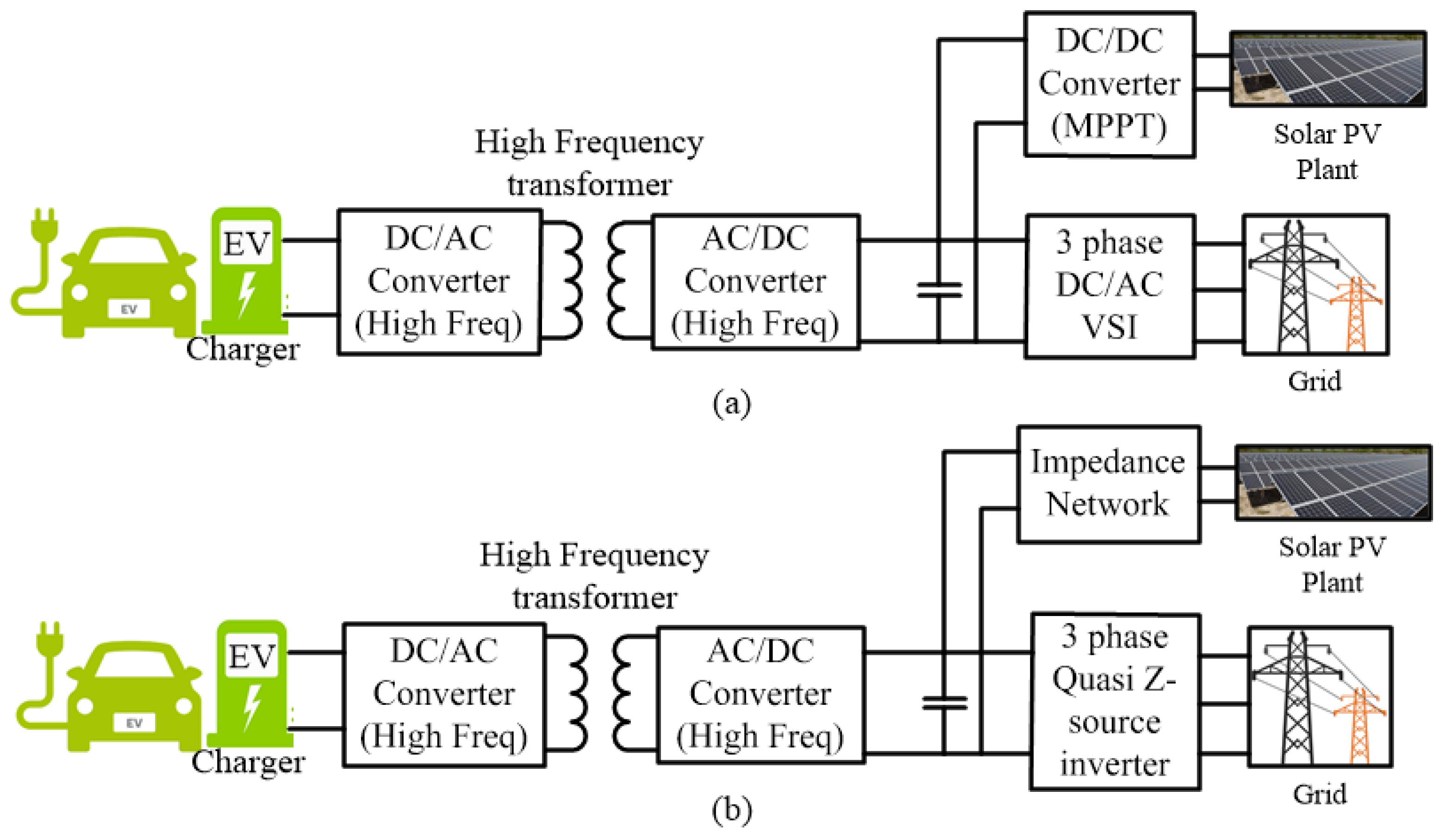
3.2. Power Converter Types for Grid Connected PV with ESD Assisted EV Charging

A grid-connected PV with energy storage device assisted EV charging system would involve the PV system, AC grid, energy storage device, EV and a power electronic converter interface to combine and link them. This converter must be capable of enabling the charging of EV from all the three utilities, i.e., PV and AC grid and facilitate charging of EVs and ESD from both the sources. This operation will guarantee that the grid can support the EV through G2V during the absence of PV and ESD and can charge the ESD for emergency power requirements. In this section, an optimal multiport converter topology that integrates EV, PV and the AC grid are proposed. The need to design such an optimal topology is necessary to ensure that the converter has low cost, high power density, and high efficiency. Conventionally, an optimal converter topology is chosen by considering several parameters, such as converter volume, efficiency, the number of components, controllability, ripples, and opportunity for efficiency improvement.

3.2.1. DC Link-Based Converter

Considering the above parameters, initially, the converter types are designed based on a DC-link. These types of systems act as a high voltage energy buffer among the ports. Conventionally, there are 3 sub converters in a DC-link based multiport converter with multiple converter topologies. These control strategies include a boost converter and MPPT algorithm integrated with the PV array for maximum power, a buck-boost converter for controlling the charging needs of EV and ESD. The complete setup is linked to the local grid with the help of a voltage source converter, which operates bidirectionally and which is accountable for power stability with the grid. The major advantage with such topology is, it’s simple power flow between PV and EV, and minimized DC/AC conversion losses. This topology also improves the AC/DC conversion of VSC for charging the EVs during peak load and when both PV and ESD were exhausted. Apart from the advantages mentioned, the topology possesses some major drawbacks, due to its large DC link capacitors and multiple controllers for each sub-converter.

3.2.2. Impedance-Network Based

Carli [35], Rasinab [36], and Rasin [37] discussed impedance network based multiport converter topology. These converters deal with a variable DC-link voltage connected with a secluded DC-DC converter for EV charging. These converters have major advantages, due to their low component count, which improves the reliability of the system. The converter topology also has an advantage over fewer control algorithms. The major drawback for such type of converters is that it is most intrinsically modular and has very high control complexity, due to variable DC link voltage. The system architecture of both DC link based multiport converter and impedance network-based converter is depicted in Figure 3a,b.

3.3. Multiport Converter

For this research, the DC link based multiport converters are used with modified control and intelligent energy management system. There are two types of multiport converters, as shown in Figure 4.
The major difference between both the possible MPC’s is the capability of isolating PV panels from the grid. The Figure 4 depicts that, both the topologies adapt a central DC-link available within the DC-DC converter. For efficient power flow management, the DC link voltage rating must be higher than the peak voltage of the system. In Figure 4a, a non-isolated DC/DC converter is adapted for achieving maximum power from the PV array. A high-frequency DC-DC conversion is adapted for EV charging station by adding a high-frequency transformer between the conversion process as per IEC 61727. For this research, the converter topology in Figure 4a is considered and tested with the proposed energy management strategy.

4. Power Flow Management

In order to design the proposed system configuration, the flow of the power between the four main elements in this system needs to be explored. The main elements are the connecting electrical grid, the PV sources, the battery storage and the EVs charging load. The decision on the need for a bi-directional power flow power electronic system, along with their sizing requirements, can be decided based on power flow management. Consequently, the research attempts to solve the power flow management problem by introducing their applicability on the studied application.
Conventionally, the power flow in a grid-connected PV/battery system is predefined by heuristic rules that consider the load demand, the PV insolation levels and the off-peak utility hours [38]. However, a dynamic grid tariff complicates the solution of the proposed system further. In a dynamic grid tariff system, the operation of the PV/battery system using the simplified heuristic rules will provide running cost solutions that largely deviate from the minimal cost operation. Thus, the research in this area has taken on an accelerated path.
In Reference [39], a Lagrangian relaxation technique is applied to determine the optimal hourly battery charging or discharging current, where the objective is to maximize the contribution of the hybrid system to the grid. The proposed technique in Reference [39] assumes there is no dispatch cost associated with the PV/Battery output power. This leads to the negligence of the battery degradation cost and its advisable operating conditions. Additionally, the formulation of the problem is limited to a thermally based electrical grid system. A predefined rule-based model is presented in Reference [40] where the battery energy storage is integrated into the renewable energy system in order to enable the PV source to act as a dispatchable unit on an hourly basis. The objective of the battery storage utilization in this paper leads to solutions that are not necessarily minimizing the running cost. Additionally, the system is sensitive to solar power forecasts.
From the above literature, it is observed that, initially, the problem formulation should account for the aging factor of the battery in order to extend the battery lifetime, and thus, increase the system reliability. The desired power flow management topology has to accommodate non-linear functions. This allows the generalization of the developed topology on different operating scenarios. An online error compensation stage has to be included in the topology to allow the system to operate effectively at mismatching conditions and forecasting deviations. Lastly, the online optimization stage should be designed to operate with low computational time, which makes it easily integrated into real-time controllers. Study regarding intelligent energy management strategy and dynamic power allocation is required in order to overcome these drawbacks and achieve the proposed optimization.

4.1. Intelligent Energy Management Strategy

The EV–PV charger in its present structure will probably charge the EV from sun-based energy, yet it does not possess any knowledge of its own. The energy price will remain low in early hours of the day as per the forecasting; hence morning period is advantageous to charge EV from the grid. While sunny afternoons provide advantage for charging from the solar. For the realization of control of EV–PV system, smart charging algorithm necessary.
The situation of charging the vehicles at parking stations has been considered where every vehicle has a predictable time of accessibility as load. The user defines the charge time window as input while parking the vehicle, and the other preferences of the user could be pricing, type of charge, etc.
The other characterization of the vehicles is its capacity, chemistry, open circuit voltage level, state of charge, temperature, etc. Depending upon the user preference and battery properties every vehicle will assign the power to the system. Hence to conclude, energy utilization of the system is optimized by considering customer preferences and load attributes using dynamic power management for loads. The control techniques, advanced demand-side power management and clients’ preferences in utility services are the main objectives for grid design. For that purpose, a given system has been designed to show the elements of the smart grid. The basic structure of the complete system is shown in Figure 5. This system accomplishes all the merits discussed and designed using energy management system, power grid, charging and battery loads. The iEMS used to control every parking deck, and these parking decks are made of multiple loads.
All the information related to the power available and the pricing as per the time period at the grid side is automatically updated to the iEMS. This process helps in simultaneously monitoring the multiple converters for making real-time decisions by iEMS.

4.2. Dynamic Power Allocation for Energy Management at EV Charging Station

The primary components of the system are EVs, ESD, energy management systems and the power grid (utility). We consider vehicles clustered in parking decks, with each parking deck under the control of an iEMS. Essentially, a cluster of vehicles and an energy storage device being controlled by an iEMS is a manageable load for the grid. The iEMS acts as an interface between the vehicles and the utility. Information about available power and pricing is regularly updated to the iEMS; multiple chargers at a parking deck are then simultaneously supervised and controlled according to the real-time inferences made by it.
At the time of plug-in, the customer will specify their preferences on the type of charge desired, estimated time of availability, willingness to participate in V2G, the price they are willing to pay for charging, etc. This information may be entered via an interface within the vehicle itself or an external user GUI available at the parking deck or from an internet profile maintained by the user for that vehicle [41]. The parking deck can be equipped with an intelligent charger at each vehicle parking space, capable of acquiring the vehicle battery state and relaying it to the iEMS via a communication medium; alternatively, each EV could be communication enabled, capable of sending its battery data to the iEMS.
The electric load that can be sustained by the utility from a parking lot will change during the course of the day as the system load varies. For vehicles willing to provide electricity back to the grid, opportunities could also arise for V2G operation depending on the grid requirements. Thus, the varying price of electricity can also be incorporated into the system information for better decision making. Using the information from the utility and the vehicles, the iEMS will make a real-time decision on power sharing to each vehicle and communicate this to the intelligent chargers.
Since the state of the system is continually changing with the arrival and departure of vehicles and changing power requirements from the utility, the system states are sampled at regular time intervals as the power allocation needs to be recomputed each time a vehicle plugs in/out, or there is a change in power availability. The system is hybrid in nature; its event-based character arises from the plug-in, plug-out activity and sampling time steps used by the iEMS for making its decisions. Moreover, the process of vehicle charging is continuous with a non-linear power consumption curve, which varies dynamically. The randomness of the preliminary states of charge, plug-in and out times and varying power curves introduce dynamicity in the system, which makes the optimization for power allocation a large scale, nonlinear, time-varying multi-objective problem with multiple constraints. In the ensuing sections, we provide a framework for system modeling and operation, addressing system goals and constraints along with optimization on a chosen objective.

4.2.1. System Modeling

The interactions in the system occur between the iEMS and the utility on the one hand and the loads (vehicles) and the iEMS on the other. The iEMS acts as broker agent, taking information about the power available from the utility on the one hand (can also be the transformer rating at the parking deck), and the vehicle battery states and user preferences on the other hand. It makes a decision on power allocation which is optimal in terms of satisfying both the parties. The system components can be modeled on ‘Agents Based Approach’ [42], in which each entity has a set of attributes, states, and functions and the entities interact with each other in order to achieve individual and system goals.

4.2.2. Optimization Objectives

A number of objectives are possible for the problem. Many objectives can be formulated around user preferences. For example, the minimization of the time taken to charge the vehicle battery for all the users, according to the price they are willing to pay. For users that do not mind compromising on the time and would like to charge at the lowest prices, the objective could be to only charge when the electricity cost is below a threshold. If the vehicle to the grid is also activated when the power flow could be facilitated such that profit to each user is maximized [43]. Another objective could be to minimize the overall power consumption (if desired by utility) while trying to guarantee a minimum threshold SoC (say, 60%) for each vehicle. In this paper an optimization problem is formulated along with the required constraints and the operating cost function is chosen as a combination of electricity grid prices and the battery degradation cost. The proposed optimization procedure uses PSO, which acts as a prediction layer for forecasting the system operation. This data is further processed for switching between the different sources as per the load requirement and power available.

4.2.3. System Constraints

The primary constraint considered here is the power available from the utility. Type of charge (slow, medium, fast), time of availability in the parking lot, the minimum desired state of charge at plug-out, maximum price the user is willing to pay for charging, the maximum power that can be absorbed by a vehicle battery, other battery requirements, etc. are other possible constraints. The user could also specify the number of miles he/she plans to drive after plug out, in which case, the SoC for achieving this will be guaranteed at plug-out. Another constraint for the iEMS could be in terms of the layout of the parking deck, the sizing and capacity of the cables will place a limit on the power that can be channeled to each vehicle(s). For a more robust system, we could consider the abrupt plug-out by a user before the stated time, and in this case, the aim would be having some fairness in the SoC distribution at every time step to have a reasonable SoC even before plug-out. Additional constraints in the system could be in terms of the bandwidth availability of the communication channel for sampling the states of the vehicles, which would limit the sampling time. System performance with packet delays and drops could also be evaluated. The final goal of the iEMS is to be flexible in terms of accommodating multiple objectives for different users. It also opens up the opportunity of dividing the station into clusters, grouping vehicles/users with common objectives and assigning the responsibility of optimizing on each cluster to a sub-iEMS thereby translating the problem into the arena of distributed control. The decision on how much power to allocate to each sub-iEMS will be made by the central iEMS or could also result from bidding actions by the sub-iEMSs.

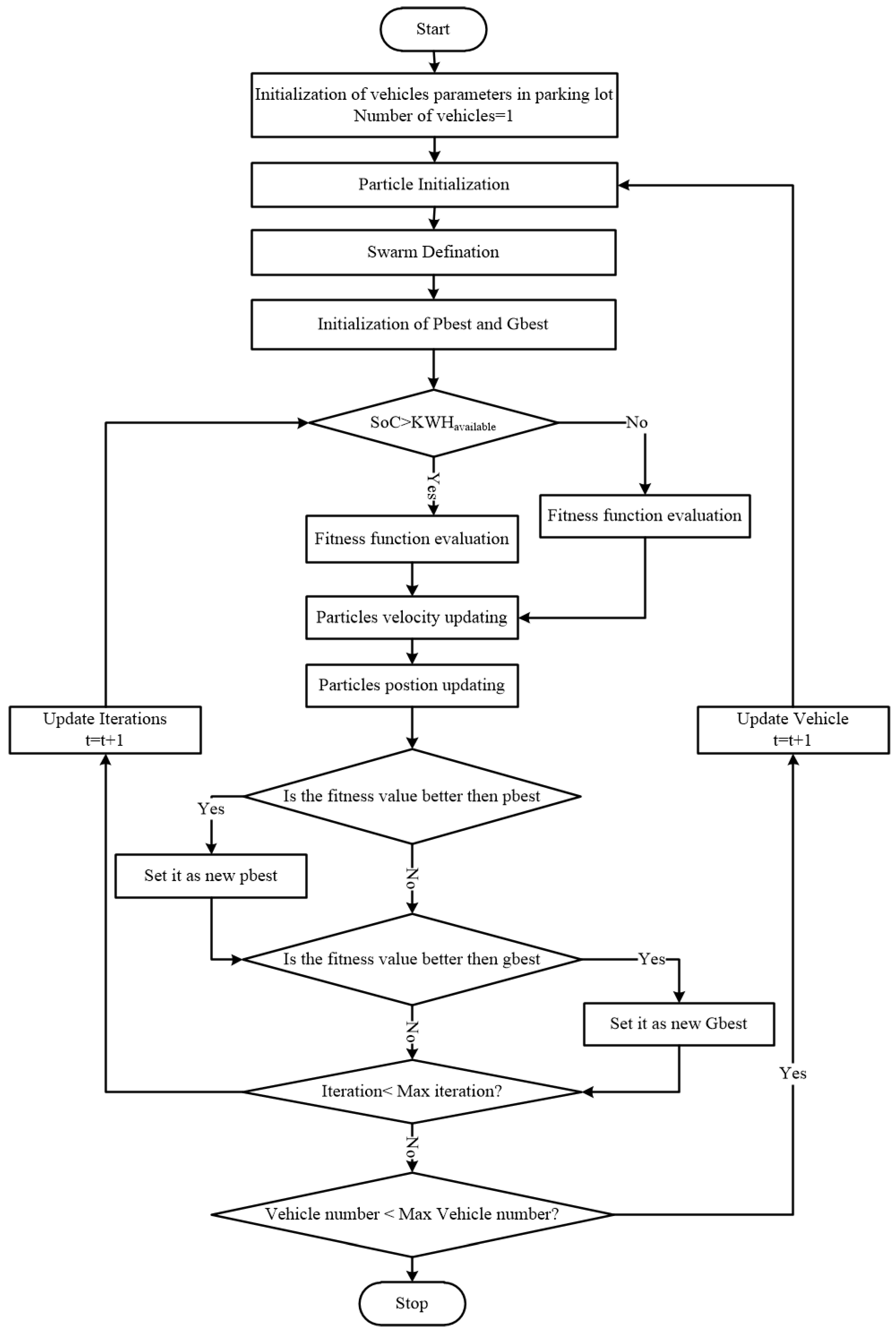
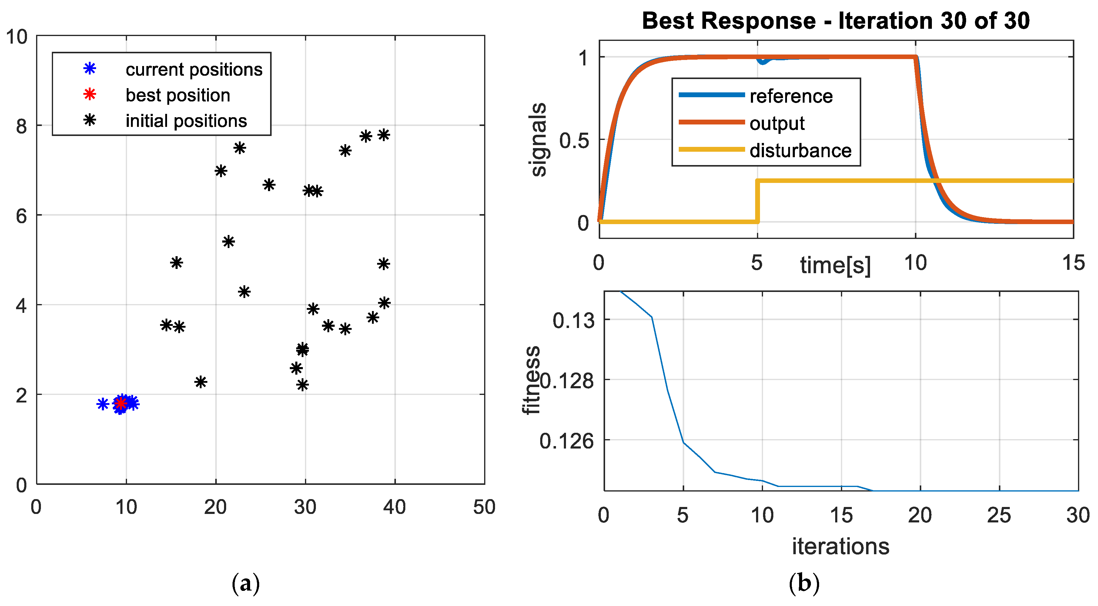
4.3. Particle Swarm Optimization

PSO is an iterative stochastic optimization algorithm, which is derived from studying the pattern in which a flock of birds or schools of fish travels [44]. Multi-dimension solution space is searched by the algorithm by collective search containing different particles and the best solution found by the other particles are communicated. The communication enables the system to take an informed a decision about the movement of each particle to find the best solution available global. Weighting factor and random variations are also considered in the algorithm to prevent any early convergence whenever local minimum is present.
Following the analysis in Reference [45], the electric vehicle system constraints are adapted from Reference [46]. Each constraint is defined by the user in the EV-iEMS. A given day is fragmented up into different intervals as per the irradiance variation pattern.

5. Methodology

The initial configuration of the grid-connected PV system with an energy storage device, explored in this paper is shown in Figure 1. The PV array, energy storage, and EV charging station (EV load) are connected at the DC link through a high frequency DC/DC converter. An interconnection between the DC link and the electric grid is achieved using a bi-directional AC/DC converter. The DC/DC converter used at the energy storage is a bi-directional power electronic interfacing converter to allows smooth operation during the battery charging and discharging modes. However, the uniqueness of this study is the reliance on the proposed configuration on the power flow management results. Thus, the shown configuration will be developed at the end of this section to reflect the findings of the optimal power flow operation through a given period of operation. The battery power ( P b ) is considered to be negative while it is charging and positive during discharging. All the charging slots, and additional loads connected with the system are summed up to form the load power ( P L ) . Here, the load power ( P L ) is considered positive in all the cases as neither the battery storage, nor the EV supply power back to the grid. The grid power ( P G ) is negative while the distributed generation feeds power into the grid, and it is considered positive when the grid is satisfying the loads.
Power flow management methodology is developed by considering all the operating modes and assumptions. Initially, the forecasting data regarding the weather conditions in the area, power generation both from PV and grid, grid tariff and the power consumption profiles of auxiliary loads and the EV charging loads are considered for a particular time period. The process of determining the forecasted data and the grid tariffs were thoroughly discussed in the literature and can be applicable [47,48].
Once the forecasted data and the grid tariffs were obtained, the objective function is defined. The defined objective function aims at optimal power scheduling between the power sources and energy storage for minimizing the daily running cost of the system. In this paper PSO method, as discussed in this section, is used to define the optimization problem. In this paper, the implementation of PSO for power flow optimization is considered to be a predictive upper-level optimization stage, where the process is based on early forecasted data. The system measurements considered for this methodology are, PV output power ( P P V ) , grid power ( P G ) , load power ( P L ) , S O C of ESD and EVs, and grid tariff ( G T ) .
The power balancing equation for GCPVS with ESD is given by Equation (3), and the state of charge of the ESD and EVs is estimated using Equation (4):
P b ( t )   =   P L ( t ) P p v ( t ) P G ( t ) ,
S O C ( t ) =   S O C ( t Δ t ) P b ( t ) Δ t Q ,
where Δ t is the time interval, and Q is the SOC of battery at the time of power exchange.
The system operation is constrained by the following limits.
S O C m i n S O C ( t ) S O C m a x ,
P b m i n P b ( t ) P b m a x ,
P G m i n P G ( t ) P G m a x .
The system constraints defined in Equations (5) and (6) are considered for improving the battery lifetime, while Equation (7) defines the limits for utilizing power from the grid. At any given time ( t ) , the total cost of the system is expressed as:
C T ( t ) = C G ( t ) + C B D ( t ) ,
where C T ( t ) is the total cost of the system, C G ( t ) is the operating cost of grid C B D ( t ) is the degradation cost of the battery.
By considering the above equations, the system objective function for operating the system for a given time period is given by Equation (9).
M i n ( C T ) = M i n t = 0 t = T [ C G ( t ) + C B D ( t ) ] ,
where the grid operating cost C G ( t ) is given in Equation (10):
C G ( t ) = G T ( t ) P G ( t ) Δ t .
However, the process of developing the degradation cost function for the energy storage device is a complex process it involves various independent factors [49]. The three major aspects impacting the operation, lifetime and health of the ESDs are battery temperature [50], average SOC [51], and the depth of discharge (DOD) [52].
By considering the temperature impact, both the charging and discharging process affect the temperatures of the ESD. This phenomenon directly affects the average power (Pavg) drawn from or to the battery as given in Equation (11). In order to account for temperature variations in both the charging and the discharging scenarios the absolute of average temperature is considered in the equation.
T = T a m b + R t h   | P a v g | ,
where T is operating temperature of the battery, T a m b is the battery pack ambient temperature, R T h is the thermal resistance of the battery pack.
The effect of battery temperature on the lifetime of the battery is calculated from the Arrhenius equation [53].
L ( T ) = a Q e b Q T ,
where a and b correspond to the curve fitting parameters.
The impact of temperature on the battery degradation cost is given by Equation (13)
C t e m p = C b a t t i t f d t T i   L ( T ) ,
where T i is the number of intervals in the total time period, and C b a t is the initial cost of the battery.
Apart from the temperature impact, average SOC of the battery also impacts the degradation rate of the battery. A firm relation between the average SOC and battery degradation cost is given by Equation (14):
C s o c = C b a t m   S O C a v g d Q f a d e   n   T i ,
where m ,   d   and   n are constants of curve fitting, and Q f a d e is the capacity fade at the end of the battery lifetime.
Finally, a relation between the lifetime of the energy storage device and the DOD of the battery are presented in References [54,55]. Equation (15) depicts the cost per kWh of the battery DOD.
C D O D = C b a t 2   N   DOD   Q   μ 2   ,
where N is the battery lifecycle for a particular DOD, and μ depicts the charging and discharging efficiency of the battery.
Considering all the factors that impact the degradation of the battery, the cost function for battery degradation is given by Equation (16) and the final objective function is achieved using (17) after discretization,
C b d = max { C t e m p ,   C D O D , C S O C a v g } ,
C T i ,   r u n = k = 1 N i [ C G ( k ) + P b ( k ) Δ t C b d ( k ) ] .
The proposed methodology for optimizing the power flow contributes to the improvement of the lifetime of the system components, especially the storage devices. The PSO implementation for the optimal selection of different power sources is illustrated in Figure 6.

6. Experimental Work

A simulation system model, containing the realistic models for the electric network and the EV, was developed to test the developed charging strategy and study its effects on the electric network. A simplified illustration of the whole simulation system is presented in Figure 7.
These models are developed in the MATLAB/Simulink environment. The main script takes data on driving distances and solar irradiance as input parameters. It then calculates the amount of power that should be supplied to the EVs and the electricity grid respectively each hour, in order for the self-consumption to be maximized and grid impact to be reduced. The parameters used for the simulation of the proposed system is given in Table 1.

6.1. Electric Network Model

The used electric network model represents a typical grid-connected PV system with an energy storage unit. The details for this synthetic electric network model are taken from MathWorks [56]. The schematic of the developed electric network is presented in Figure 7. The developed system consists of a 20 kW solar array connected to a 5 kHz boost converter with incremental conductance MPPT algorithm. The PV network is connected to the grid via a three-phase voltage source converter (VSC). The VSC can be operated both in inverter and rectifier mode in order to facilitate the power flow both from the grid to charging stations and from PV to the grid. A 25-kVA high-frequency transformer is used to provide isolation between GCPV and the EV charging, ESD unit.

6.2. EV Charging Model

The EVs can be modeled as systems composed of many dynamic dependencies. The key components in the EV models are the charger and the battery. The EV model used in this research is sourced from Reference [57]. It consists of blocks for the driving schedules, charger logic, converter losses and the battery model as presented in Figure 8. The driving schedule block collects and passes on the data regarding the EV ID, EV address and the EV demand D o D E V , n . The EV demand describes the Depth of Discharge (DoD) of the nth EV. The EV ID specifies which of the EVs are connected and the address specifies the household node for each EV. As soon as an EV is connected to the electric network, the driving schedule block relays the details for the charger logic block and updates the battery DoD information to the battery model block.
The charger logic block receives data from four sources. The first input comes from the battery model block, which continuously updates the charger logic block with the current S o C E V , n . The second input comes from the EV fleet aggregator who submits the EV schedules. These schedules are directly used by the charger logic block. The third input receives the current voltages from the electric network model. The fourth input comes from the driving schedule. The charger’s main function is to convert the AC power into DC power, which is essential to charge the battery. The charger logic block processes the received data and regulates the battery charging in a manner that the local network voltage limits, set for each EV separately, are not violated. It also computes the appropriate charging power rates as they are dependent on the batteries’ S o C E V , n levels, as explained in Reference [57].

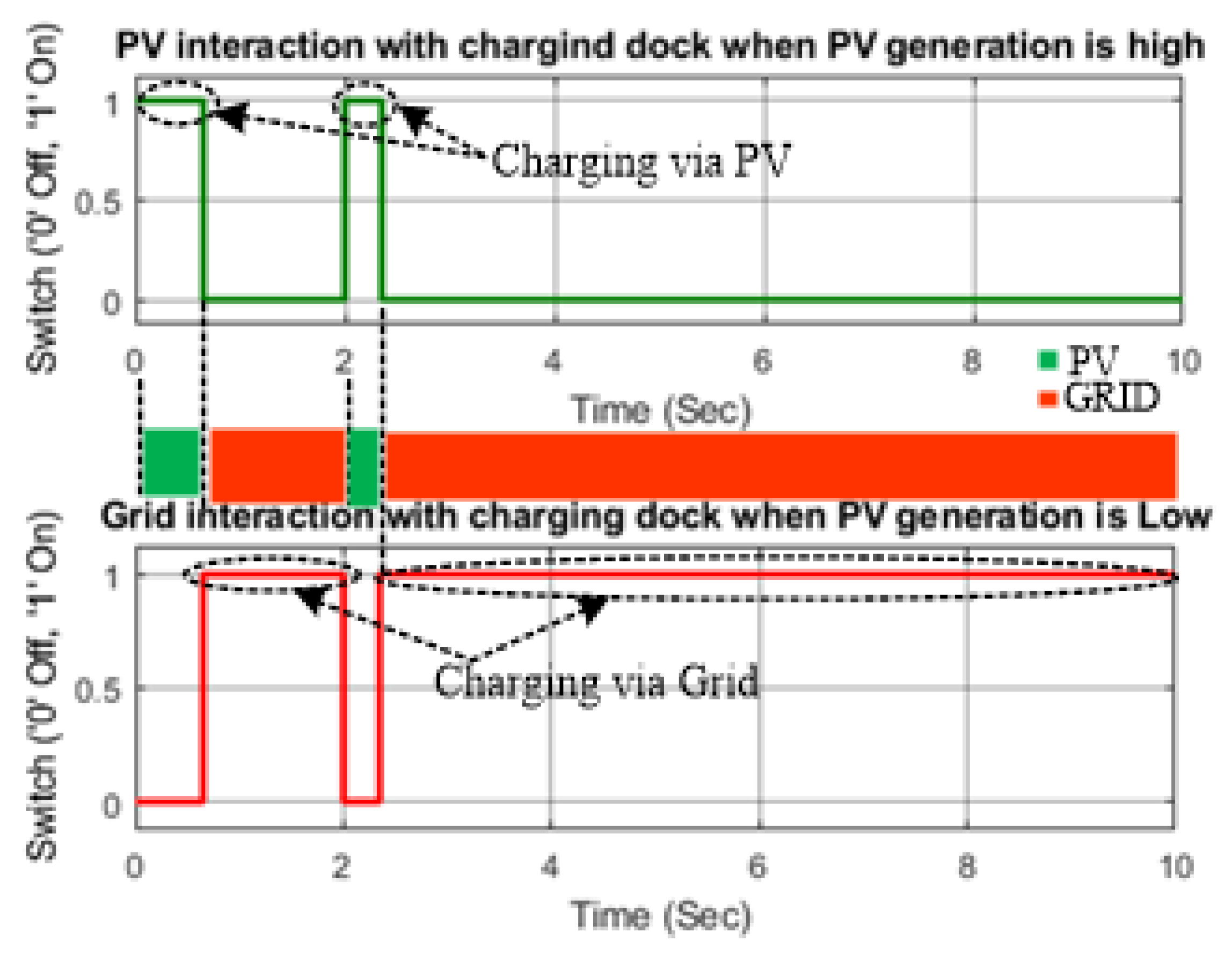
6.3. Modes of Operation

The model is built on the idea of matching hourly charging powers and PV power generation, meeting daily charging demands and achieving constant power exchange with the electricity grid. Since the driving distance for each EV is randomly selected each day, the charging demand of the car park is unique for each day of the simulated year. The level of self-sufficiency depends on the amount of installed PV power. If the accumulated PV energy generation for one day equals the car park demand, all PV generated power is supplied directly to the EVs. If the accumulated PV energy generation falls short of the daily car park demand, the deficit is supplied from the electricity grid, evenly distributed over all workday hours. If the daily PV energy generation exceeds the car park demand; the excess power is supplied to the electricity grid as evenly distributed as possible. In this case, where the PV system generates excess energy, the power exchange with the electricity grid is different each hour, depending on whether the hourly PV energy generation is higher or lower than the mean excess energy generation. The complete scenario of charging the EVS by considering all the constraints is explained in nine different modes, as shown in Figure 9.
Mode 1: PV generation full, EV load Available and ESD has less charge.
In this scenario, the PV generation is happening under standard test conditions and considered to generate maximum power. Since all the systems EV1, EV2 and ESD act as loads and are ready to charge, and the power demanded is greater than the power generated from the PV. In this condition, the grid supports the PV in satisfying the load.
Mode 2: PV generation partial, EV load Available and ESD has less charge.
In this scenario, the PV generation is considered to happen under varying irradiance conditions. Here the power generated from the PV is low. Since all the systems EV1, EV2 and ESD act as loads and are ready to charge, and the power demanded is greater than the power generated from the PV. In this condition, the grid supports the PV in satisfying the load.
Mode 3: PV generation partial, EV load Available and ESD is fully charged.
In this scenario, the PV generation is considered to happen under varying irradiance conditions. Here the power generated from the PV is low. Since both EV1 and EV2 act as loads and are ready to charge, and the power demanded is greater than the power generated from the PV. In this condition, both the grid and ESD supports the PV in satisfying the load depending upon the requirement of the user.
Mode 4: No PV generation, EV load Available and ESD is fully charged.
In this scenario, the PV generation is zero. Since both the EVs are ready to charge, and the power demanded is greater than the power generated from the PV and power available from the battery. In this condition, the grid supports the ESD in satisfying the load and PV remains disconnected from the system.
Mode 5: No PV generation, EV load Available and ESD has less charge.
In this scenario, the grid satisfies the changing needs of the EV station. The PV remains disconnected from the charging dock, and once the charging needs of the EVs are satisfied, and the load connected to the utility is less, then the grid charges the ESD.
Mode 6: PV generation full, Partial EV load Available and ESD has less charge.
In this scenario, the PV generation is happening under standard test conditions and considered to generate maximum power. Since the ESD has less charge, and EV load available is less and ready to charge, the PV satisfies the EV load first and then charges the ESD.
Mode 7: PV generation partial, Partial EV load Available and ESD has less charge.
In this scenario, the PV generation is considered to happen under varying irradiance conditions. Here the power generated from the PV is low. Since the ESD has less charge, EV load available is less and ready to charge, and the power demanded is greater than the power generated from the PV. In this condition, PV satisfies the EV load first and then charges the ESD depending upon the generating capability of the PV.
Mode 8: No PV generation, No EV load Available and ESD is fully charged.
In this scenario, the grid satisfies the utilities connected to it. The ESD remains connected with the charging docks.
Mode 9: PV generation full, No EV load Available and ESD is fully charged.
In this scenario, the PV generation is happening under standard test conditions and considered to generate maximum power. Since the EV load is not available and the ESD is fully charged, the PV transfers its power to the grid.
By bearing these scenarios in mind, the model, considered above, is simulated to observe the efficiency of the proposed charging and converter control strategy. The optimal power flow is achieved by adapting the cost function achieved in Equation (17). The forecasting data to perform the experiment is considered as follows:
The irradiance profile for performing the experiment is considered as depicted in Figure 10.
From Figure 10, it is observed that there is variation in irradiance at multiple instances, this is considered to replicate the behavior of PV system in real-time. By considering the real-time operation, the PV systems depict five times the difference in energy yield for change in environmental conditions. Due to this change, the ratings of the PV converter can be resized by 30%, which corresponds to a 3.2% loss of energy [58]. Apart from the change in irradiance, the impact of using two stage conversion for grid-connected PV system, the switching frequencies, the high frequency DC-DC converter at the charging end and the impact of varying loads in the system also contribute for the power loss in the system. A detailed explanation on power loss in grid-connected PV system and the impact of EV/ESD charging and discharging in a grid-connected system were given in References [59,60,61]. Since the system design considered for this research investigates the best design for grid-connected PV system to achieve efficient charging of EV and ESD, and the power flow in the considered to be unidirectional, the power loss calculation is neglected.
Apart from the irradiance profile, the major assumptions considered for this research are as follow: The SOC of ESD is 10%and it is considered to be in charging mode and hence it acts as a load, and the SOC of EV1 is 40%, and SOC of EV 2 is 30% and were connected with the GCPV. The process of implementing PSO for developing the proposed methodology as per the forecasted data is given in the following steps.
Initialization of PSO:
Objective: For charging the vehicle finding an optimal power source using Equation (17).
Topology: Swarm optimization star configuration is used to ensure that all particle communicates with each other.
Definition of particles: Depending upon the power capacity of PV and ESD, particles are defined.
Fitness Function: The equation is used to maximize and minimize the power generated during the charging and discharging process.
Search Space: (Constraints) The major constraints to be considered for this problem is that the hours must be a positive real number, which is limited by arrival and departure time.
PSO parameters: The PSO parameters tested for this control are depicted in Table 2.
The best performance of the proposed switching strategy as per the power available is obtained from the PSO implemented and the corresponding results are depicted in Figure 11.
Figure 11a shows the best position for feeding the load continuously as per the power available from different sources. The initial position defines the power generation capacity of various sources at the time of interaction with the load. Whereas, the current position defines the source feeding the load irrespective of the availability of the source or the status of the load, and the best position is defined based on the load power and generation capacity. Figure 11b depicts the best response of the PSO in finding the optimal power flow path for satisfying the loads connected at the DC link.
Considering the optimal power flow path defined by the PSO for the forecasted data, the experimental analysis is carried out as follows:
Initially, the PV generation is set to high by operating it under STC. During this period the PV is able to charge the EVs with rated power without any support from the grid. After 0.6 s, the PV generation is set to zero by varying the irradiance of the system. Here the grid comes into the scenario, in order to support the EV charging. At 2.4 s, the PV generation is minimized to generate 20% of the rated power by varying the irradiance of the system, as shown in Figure 10. In this case, the grid continuously supports the charging process of the system. The PSO here monitors the generation and load profile of both the grid and EV charging docks in order to provide fast switching between the sources as depicted in Figure 12.
The voltage at the DC link is maintained constant around 500 V, as shown in Figure 13.
A high-frequency transformer is used to provide isolation between charging docks, ESD and the grid-connected PV system. Finally, as per the specification of the vehicle mentioned in the section, the EVs were able to charge at rated voltage and current even with disturbances in PV generation, as shown in Figure 14a,b.
From the results, it can be observed that the developed power flow optimization algorithm, effectively identifies the availability of power generated by various sources and schedules them as per the load requirement. The developed algorithm achieves fast switching between various sources in order to satisfy the loads continuously without any interruption. Further, the developed algorithm can also be adapted for improving the lifetime of the energy storage device, which is integrated with the system.

7. Conclusions

In this paper, an optimized power flow algorithm for grid-connected photovoltaic system with an energy storage device for charging of electric vehicles is realized. The following objectives are achieved throughout the paper:
  • The need to adopt renewable energy systems for the charging of electric vehicles is studied.
  • The advantage of using an energy storage device with grid integrated PV systems for charging EVs is depicted.
  • The major role of converters in achieving optimal and bidirectional power flow between various sources and loads is realized, and a multiport converter is designed for achieving the objective.
  • The need for an intelligent-energy management system for operating the power converter as per the availability of power from the sources and demand on the load side is achieved by developing an optimal power flow algorithm.
  • The developed algorithm is tested with a simulation setup by observing the various modes of operation on the system.
All results and conclusions are based on the assumption that the model created in MATLAB is implemented as a system that adjusts EV charging. A grid-connected PV–EV charging system with an energy storage device is developed in this paper. A multiport converter is designed to accommodate efficient power flow between multiple sources and the loads. The developed converter is controlled by adapting particle swarm optimization, which acts as an intelligent energy management system for dynamic power management at the charging station. An objective function is formulated for scheduling optimal power flow between various sources and loads in the system. The simulation results depict that the new control strategy efficiently shifts between the sources within a stipulated time and continuously supports the charging station.

Author Contributions

Conceptualization, methodology, software, validation, and formal analysis, M.J., V.S.B.K. and M.A.K.; Investigation, A.H. and F.B.; Resources, and data curation, M.J.; writing—original draft preparation, writing—review and editing, and visualization, V.S.B.K. and M.A.K.; supervision, A.H. and F.B.; project administration, A.H. and F.B.

Funding

This research received no external funding.

Conflicts of Interest

The authors declare no conflict of interest.

References

  1. Chan, C.C.; Wong, Y.S. Electric Vehicles Charge Forward. IEEE Power Energy Mag. 2004, 2, 24–33. [Google Scholar] [CrossRef]
  2. Hidrue, M.K.; Parsons, G.R.; Kempton, W.; Gardner, M.P. Willingness to pay for electric vehicles and their attributes. Resour. Energy Econ. 2011, 33, 686–705. [Google Scholar] [CrossRef] [Green Version]
  3. Yilmaz, M.; Krein, P.T. Review of battery charger topologies, charging power levels, and infrastructure for plug-in electric and hybrid vehicles. IEEE Trans. Power Electron. 2013, 28, 2151–2169. [Google Scholar] [CrossRef]
  4. Fairley, P. Speed bumps ahead for electric-vehicle charging. IEEE Spectr. 2010, 47, 13–14. [Google Scholar] [CrossRef]
  5. Clement-Nyns, K.; Haesen, E.; Driesen, J. The impact of Charging plug-in hybrid electric vehicles on a residential distribution grid. IEEE Trans. Power Syst. 2010, 25, 371–380. [Google Scholar] [CrossRef]
  6. Yunus, K.; la Parra, H.Z.D.; Reza, M. Distribution Grid Impact of Plug-In Electric Vehicles Charging at Fast Charging Stations Using Stochastic Charging Model. In Proceedings of the 2011 14th European Conference on Power Electronics and Applications, Birmingham, UK, 30 August–1 September 2011; pp. 1–11. [Google Scholar]
  7. Botsford, C.; Szczepanek, A. Fast Charging vs. Slow Charging: Pros and cons for the New Age of Electric Vehicles. In Proceedings of the EVS24 International Battery, Hybrid and Fuel Cell Electric Vehicle Symposium, Stavanger, Norway, 13–16 May 2009. [Google Scholar]
  8. Gnann, T.; Funke, S.; Jakobsson, N.; Plotz, P.; Sprei, F.; Bennehag, A. Fast charging infrastructure for electric vehicles: Today’s situation and future needs. Transp. Res. Part D Transp. Environ. 2018, 62, 314–329. [Google Scholar] [CrossRef]
  9. Morrow, K.; Karner, D.; Francfort, J. Plug-in Hybrid Electric Vehicle Charging Infrastructure Review (U. S. Department of Energy Vehicle Technologies Program—Advanced Vehicle Testing Activity); Idaho National Laboratory (INL): Idaho Falls, ID, USA, 2008.
  10. Deb, S.; Tammi, K.; Kalita, K.; Mahanta, P. Review of recent trends in charging infrastructure planning for electric vehicles. Wiley Interdiscip. Rev. Energy Environ. 2018, 7, e306. [Google Scholar] [CrossRef]
  11. Dickerman, L.; Harrison, J. A New Car, a New Grid. IEEE Power Energy Mag. 2010, 8, 55–61. [Google Scholar] [CrossRef]
  12. Badea, G.; Felseghi, R.A.; Varlam, M.; Filote, C.; Culcer, M.; Iliescu, M.; Răboacă, M. Design and simulation of romanian solar energy charging station for electric vehicles. Energies 2019, 12, 74. [Google Scholar] [CrossRef]
  13. IEA PVPS. Trends 2015 in Photovoltaic Applications; IEA PVPS: Bangkok, Thailand, 2015. [Google Scholar]
  14. Nehrir, M.H.; Wang, C.; Strunz, K.; Aki, H.; Ramakumar, R.; Bing, J.; Miao, Z.; Salameh, Z. A review of hybrid renewable/alternative energy systems for electric power generation: Configurations, control, and applications. IEEE Trans. Sustain. Energy 2011, 2, 392–403. [Google Scholar] [CrossRef]
  15. Strunz, K.; Abbasi, E.; Huu, D.N. DC microgrid for wind and solar power integration. IEEE J. Emerg. Sel. Top. Power Electron. 2014, 2, 115–126. [Google Scholar] [CrossRef]
  16. Cingoz, F.; Elrayyah, A.; Sozer, Y. Optimized Resource Management for PV-Fuel-Cell-Based Microgrids Using Load Characterizations. IEEE Trans. Ind. Appl. 2016, 52, 1723–1735. [Google Scholar] [CrossRef]
  17. Varaha, K.; Bharath, S.; Khan, M.A. Applications of Artificial Intelligence Techniques in Engineering 698; Springer: Singapore, 2019. [Google Scholar]
  18. Kurukuru, V.S.B.; Khan, M.A.; Singh, R. Performance optimization of UPFC assisted hybrid power system. In Proceedings of the 2018 IEEMA Engineer Infinite Conference (eTechNxT), New Delhi, India, 13–14 March 2018; pp. 1–6. [Google Scholar]
  19. Eren, Y.; Erdinc, O.; Gorgun, H.; Uzunoglu, M.; Vural, B. A fuzzy logic based supervisory controller for an FC/UC hybrid vehicular power system. Int. J. Hydrog. Energy 2009, 34, 8681–8694. [Google Scholar] [CrossRef]
  20. Badawy, M.O.; Sozer, Y. Power Flow Management of a Grid Tied PV-Battery System for Electric Vehicles Charging. IEEE Trans. Ind. Appl. 2017, 53, 1347–1357. [Google Scholar] [CrossRef]
  21. Carbone, R. Grid-connected photovoltaic systems with energy storage. In Proceedings of the 2009 International Conference on Clean Electrical Power (ICCEP), Capri, Italy, 9–11 June 2009; pp. 760–767. [Google Scholar]
  22. Beltran, H.; Pérez, E.; Aparicio, N.; Rodriguez, P. Daily solar energy estimation for minimizing energy storage requirements in PV power plants. IEEE Trans. Sustain. Energy 2013, 4, 474–481. [Google Scholar] [CrossRef]
  23. F. OECD/IEA. Medium-Term Market Report/Aut; IEA: Paris, France, 2014. [Google Scholar]
  24. Deb, S.; Tammi, K.; Kalita, K.; Mahanta, P. Impact of electric vehicle charging station load on distribution network. Energies 2018, 11, 178. [Google Scholar] [CrossRef]
  25. Bauer, P.; Zhou, Y.; Doppler, J.; Stembridge, N. Charging of Electric Vehicles and Impact on the Grid. In Proceedings of the 13th Mechatronika 2010, Trencianske Teplice, Slovakia, 2–4 June 2010; pp. 121–127. [Google Scholar]
  26. SAE. SAE Electric Vehicle and Plug-in Hybrid Electric Vehicle Conductive Charge Coupler J1772; SAE: Warrendale, PA, USA; Troy, MI, USA, 2010. [Google Scholar]
  27. IEC 62196. Plugs, Socket-Outlets, Vehicle Connectors and Vehicle Inlets—Conductive Charging of Electric Vehicles—Part 1, 2, 3; International Electrotechnical Commission: Geneva, Switzerland, 2014. [Google Scholar]
  28. IEC 61851. Electric Vehicle Conductive Charging System—Part 1, 21, 23, 24; International Electrotechnical Commission: Geneva, Switzerland, 2014. [Google Scholar]
  29. Kubel, M. Design Guide for Combined Charging System; CharIN e.V: Berlin, Germany, 2015. [Google Scholar]
  30. CHA Association. Technical Specifications of Quick Charger for the Electric Vehicle; CHA Association: Washington, DC, USA, 2010. [Google Scholar]
  31. Tesla EV Charging and Supercharging Technique. 2019. Available online: www.teslamotors.com (accessed on 24 April 2019).
  32. Messagie, M.; Boureima, F.-S.; Coosemans, T.; Macharis, C.; van Mierlo, J. A Range-Based Vehicle Life Cycle Assessment Incorporating Variability in the Environmental Assessment of Different Vehicle Technologies and Fuels. Energies 2014, 7, 1467–1482. [Google Scholar] [CrossRef]
  33. Messenger, R.A.; Abtahi, A. Photovoltaic Systems Engineering; CRC Press: Boca Raton, FL, USA, 2017. [Google Scholar]
  34. Stapleton, G.; Neill, S. Grid-Connected Solar Electric Systems: The Earthscan Expert Handbook for Planning, Design and Installation; Routledge: Abingdon, UK, 2011. [Google Scholar]
  35. Carli, G.; Williamson, S.S. Technical Considerations on Power Conversion for Electric and Plug-in Hybrid Electric Vehicle Battery Charging in Photovoltaic Installations. IEEE Trans. Power Electron. 2013, 28, 5784–5792. [Google Scholar] [CrossRef]
  36. Rasin, Z.; Rahman, M.F.; Teknikal, U. Grid-connected Quasi-Z-Source PV Inverter for ElectricVehicle Charging Station. In Proceedings of the International Conference on Renewable Energy Research and Applications, Madrid, Spain, 20–23 October 2013; pp. 627–632. [Google Scholar]
  37. Rasin, Z.; Ahsanullah, K.; Rahman, M.F. Design and Simulation of Quasi-Z-Source Grid-connected PV Inverter with Bidirectional Power Flow for Battery Storage Management. In Proceedings of the IECON 2013-39th Annual Conference of the IEEE Industrial Electronics Society, Vienna, Austria, 10–13 November 2013; pp. 1589–1594. [Google Scholar]
  38. Rydh, C.J.; Sandén, B.A. Energy analysis of batteries in photovoltaic systems. Part II: Energy return factors and overall battery efficiencies. Energy Convers. Manag. 2005, 46, 1980–2000. [Google Scholar] [CrossRef]
  39. Chiang, S.J.; Chang, K.T.; Yen, C.Y. Residential Photovoltaic Energy Storage System. IEEE Trans. Ind. Electron. 1998, 45, 385–394. [Google Scholar] [CrossRef]
  40. Riffonneau, Y.; Bacha, S.; Barruel, F.; Ploix, S. Optimal power flow management for grid connected PV systems with batteries. IEEE Trans. Sustain. Energy 2011, 2, 309–320. [Google Scholar] [CrossRef]
  41. Bagula, A.; Castelli, L.; Zennaro, M. On the Design of Smart Parking Networks in the Smart Cities: An Optimal Sensor Placement Model. Sensors 2015, 15, 15443–15467. [Google Scholar] [CrossRef] [PubMed] [Green Version]
  42. Macal, C.M.; North, M.J. Tutorial on Agent-based Modeling and Simulation. In Proceedings of the 37th Winter Simulation Conference, Orlando, FL, USA, 4–7 December 2005; pp. 2–15. [Google Scholar] [CrossRef]
  43. Hutson, C.; Venayagamoorthy, G.K.; Corzine, K.A. Intelligent Scheduling of Hybrid and Electric Vehicle Storage Capacity in a Parking Lot for Profit Maximization in Grid Power Transactions. In Proceedings of the 2008 IEEE Energy 2030 Conference, Atlanta, GA, USA, 17–18 November 2008; pp. 1–8. [Google Scholar]
  44. Kennedy, J. Particle Swarm Optimization. In Encyclopedia of Machine Learning; Springer: Berlin, Germany, 2010; pp. 745–817. [Google Scholar]
  45. Valle, Y.; Venayagamoorthy, G.K.; Mohagheghi, S.; Jean-Carlos Hernandez, R.G. Harley, Particle Swarm Optimization: Basic Concepts, Variants and Applications in Power Systems. IEEE Trans. Evol. Comput. 2008, 12, 171–195. [Google Scholar] [CrossRef]
  46. Mahindra Everito. Available online: http://www.mahindraverito.com/everito/discover-the-new-verito.aspx (accessed on 5 May 2019).
  47. Li, G.; Liu, C.C.; Mattson, C.; Lawarrée, J. Day-ahead electricity price forecasting in a grid environment. IEEE Trans. Power Syst. 2007, 22, 266–274. [Google Scholar] [CrossRef]
  48. Pindoriya, N.M.; Singh, S.N.; Singh, S.K. An adaptive wavelet neural network-based energy price forecasting in electricity markets. IEEE Trans. Power Syst. 2008, 23, 1423–1432. [Google Scholar] [CrossRef]
  49. Mazadi, M.; Rosehart, W.; Zareipour, H. Impact of Wind Generation on Electricity Markets: A Chance-Constrained Nash Cournot model. Iran. J. Sci. Technol. Trans. Electr. Eng. 2012, 36, 51–66. [Google Scholar]
  50. Hoke, A.; Brissette, A.; Smith, K.; Pratt, A.; Maksimovic, D. Accounting for lithium-ion battery degradation in electric vehicle charging optimization. IEEE J. Emerg. Sel. Top. Power Electron. 2014, 2, 691–700. [Google Scholar] [CrossRef]
  51. Motamedi, A.; Zareipour, H.; Rosehart, W.D. Electricity price and demand forecasting in smart grids. IEEE Trans. Smart Grid 2012, 3, 664–674. [Google Scholar] [CrossRef]
  52. Liu, S.; Wang, J.; Liu, Q.; Tang, J.; Liu, H.; Fang, Z. Deep-Discharging Li-Ion Battery State of Charge Estimation Using a Partial Adaptive Forgetting Factors Least Square Method. IEEE Access 2019, 7, 47339–47352. [Google Scholar] [CrossRef]
  53. Yang, Y.; Hu, X.; Qing, D.; Chen, F. Arrhenius equation-based cell-health assessment: Application to thermal energy management design of a HEV NiMH battery pack. Energies 2013, 6, 2709–2725. [Google Scholar] [CrossRef]
  54. Markel, T.; Smith, K.; Pesaran, A.A. Improving Petroleum Displacement Potential of PHEVs Using Enhanced Charging Scenarios; Elsevier: Amsterdam, The Netherlands, 2010. [Google Scholar]
  55. Xu, B. Degradation-Limiting Optimization of Battery Energy Storage Systems Operation; Location Power Systems Laboratory ETH Zurich: Zürich, Switzerland, 2013. [Google Scholar]
  56. Detailed Model of a 100-kW Grid-Connected PV Array—MATLAB & Simulink—MathWorks France. Available online: https://fr.mathworks.com/help/physmod/sps/examples/detailed-model-of-a-100-kw-grid-connected-pv-array.html (accessed on 5 May 2019).
  57. Ma, C.; Marten, F.; Töbermann, J.; Braun, M.; Iwes, F. Evaluation of Modeling and Simulation Complexity on Studying the Impacts of Electrical Vehicles Fleets in Distribution Systems. In Proceedings of the 2014 Power Systems Computation Conference, Wroclaw, Poland, 18–22 August 2014. [Google Scholar]
  58. Mouli, G.R.C. Charging Electric Vehicles from Solar Energy: Power Converter, Charging Algorithm and System Design. Ph.D. Thesis, Delft University of Technology, Delft, The Netherlands, 2018. [Google Scholar]
  59. Mouli, G.R.C.; Bauer, P.; Zeman, M. System design for a solar powered electric vehicle charging station for workplaces. Appl. Energy 2016, 168, 434–443. [Google Scholar] [CrossRef] [Green Version]
  60. Apostolaki-Iosifidou, E.; Codani, P.; Kempton, W. Measurement of power loss during electric vehicle charging and discharging. Energy 2017, 127, 730–742. [Google Scholar] [CrossRef]
  61. Wu, T.F.; Chang, C.H.; Chang, Y.D.; Lee, K.Y. Power loss analysis of grid connection photovoltaic systems. In Proceedings of the 2009 International Conference on Power Electronics and Drive Systems (PEDS), Taipei, Taiwan, 2–5 November 2009; pp. 326–331. [Google Scholar]
Figure 1. An overview of the proposed hybrid system.
Energies 12 02334 g001
Figure 2. System architectures for electric vehicle (EV)—photovoltaic (PV) charging using multiport converters.
Energies 12 02334 g002
Figure 3. Block representation of grid-connected PV–EV converters (a) DC-link based converter, (b) Impedance-network based converter.
Energies 12 02334 g003
Figure 4. Block representation of multiport converters. (a) MPCA; (b) MPCB.
Energies 12 02334 g004
Figure 5. Architecture of the intelligent energy management system.
Energies 12 02334 g005
Figure 6. Implementation of particle swarm optimization (PSO) for the optimal selection of power source.
Energies 12 02334 g006
Figure 7. Simulink implementation of grid-connected PV–EV (GCPE) charging architecture with energy storage device (ESD) and intelligent energy management system (iEMS).
Energies 12 02334 g007
Figure 8. Architecture of EV charging model.
Energies 12 02334 g008
Figure 9. Modes of operation for GCPE charging architecture with an ESD and iEMS.
Energies 12 02334 g009
Figure 10. Irradiance variation for PV array.
Energies 12 02334 g010
Figure 11. Best switching strategy as per the power available. (a) Best position for feeding the load; (b) Best response of the algorithm.
Energies 12 02334 g011
Figure 12. Availability of PV and grid for charging of EVs.
Energies 12 02334 g012
Figure 13. DC link voltage of grid-connected PV system.
Energies 12 02334 g013
Figure 14. Battery characteristics while charging for electric vehicles (a) EV1 and (b) EV2.
Energies 12 02334 g014
Table 1. Simulation parameters of grid-connected PV–EV charging station with an energy storage unit.
ComponentsRating
Solar Array20 kW
Boost Converter5 kHz, 500 V
DC link Voltage500 V
Grid Parameters2500 MVA, 120 kV
High Frequency Transformer25 kva, 5 kHz, 500:80:80, three winding transformer
Electric VehicleMahindra severity
EV BatteryLithium Battery
Nominal Voltage = 72 V
Rated Capacity = 200 Ah
Energy Storage DeviceRated Power = 150 kW
Power Conversion Efficiency = 90%
Table 2. Tested PSO parameters.
ParametersValue
No of particles in swarm24
No of iterations30
Parameters to be identified2
Search Space Range[0 50; 0 10];
Swarm declarationZero
Velocity Clamping[3; 1];

