Article

Improvement of Combustion Process of Spark-Ignited Aviation Wankel Engine

Central Institute of Aviation Motors n.a. P.I. Baranov, Aviamotornaya St., 2, Moscow 111116, Russia
*
Author to whom correspondence should be addressed.
Energies 2019, 12(12), 2292; https://doi.org/10.3390/en12122292
Submission received: 15 May 2019 / Revised: 8 June 2019 / Accepted: 13 June 2019 / Published: 15 June 2019

Abstract

:
This paper deals with the creation of modern high-performance aircraft power units based on the Wankel rotary piston engine. One of the main problems of Wankel engines is high specific fuel consumption. This paper solves the problem of improving the efficiency of this type of engine. The mathematical model of non-stationary processes of transfer of momentum, energy, mass, and the concentration of reacting substances in the estimated volume provides for the determination of local gas parameters in the entire computational region, which are presented as a sum of averaged and pulsation components. The k-ζ-f model is used as the turbulence model; the combustion is described by the coherent flame model (CFM) based on the concept of laminar flame propagation. As a result of the calculation, we obtained the values of temperature, pressure, and velocity of the working fluid in the working chamber cross-sections of a rotary–piston engine. Various options of the rotor recess shape are considered. Based on the data obtained, the rotor design was improved. The offered shape of the rotor recess has reduced emissions of both nitrogen oxides and carbon dioxide.

1. Introduction

Wankel engines (WEs), in comparison with traditional engines with a crank mechanism, have a smaller weight and dimensions. In this regard, they are well suited for use on aircrafts. WE high performance should be provided by improving the efficiency of the processes of intake, exhaust, and the combustion of the fuel–air mixture. These engines are also characterized by a fewer number of parts in comparison with traditional piston engines [1,2]. In addition, due to the rotational motion of the rotor, WEs have an advantage in terms of low vibration [2]. On the other hand, these engines have a high fuel consumption and relatively low engine life. Due to these reasons, it is necessary to increase the WE operation efficiency and improve the engine’s life. This study is aimed at solving the first problem; we only mention that a possible solution of the second problem is the use of perspective materials for the manufacture of seals and the hardening of the stator surface.
The simulation of gas and thermodynamic processes in the WE working chamber is hampered by its geometrical features. The work of the Wankel engine with external air–fuel mixing (fuel injection at the inlet) and ignition from an electric spark are considered. The change in working volumes is provided by the rotation of trochoidal triangular rotor in almost elliptical (epitrochoidal) stator housing (Figure 1) [3]. The geometry of these parts forming the combustion chamber in the WE is described by a known relationship [4,5].
The combustion chamber geometry strongly affects the characteristics of the working fluid flow, and, as a result, the efficiency of the fuel combustion process [6]. In this work, we conducted numerical studies of the processes of air–fuel mixing and combustion in the WE working chamber with various combustion chambers (CC) in the rotor. The shapes of the rotor recesses were chosen in such a way as to accelerate the propagation of the flame front through the working chamber. Based on the research findings, a conclusion on the degree of influence of the shape of the combustion chamber on the performance of the rotary piston engine is given. In addition, the rotor design modification is carried out.
The object of the study was a single-section Wankel engine with an intake port injection (Figure 1a,b).
The engine is equipped with a fail-operative ignition system, which is caused both by the specifics of the fuel combustion process and by increasing the reliability of its operation. The target indicators for the developed WE are as follows: Effective power, Ne = 70–100 hp; minimum specific fuel consumption ge, up to 210 g/(hp·h); engine specific weight, 0.42–0.45. The studies were conducted at the nominal mode of operation, with the rotational speed of the eccentric shaft n = 6500 rpm.

2. Mathematical Model

It is worth noting that the one-dimensional approach, which is often used to estimate effective indicators of the WE and which implies a change in the operating parameters of the engine in one or several zones of the working chamber, does not allow for a proper consideration of the geometry of the WE working chamber. There is also no opportunity to optimize the position and ignition points for spark plugs and to evaluate the efficiency of filling. These features are correctly described using the three-dimensional approach [7,8].
The mathematical model of the working process of traditional piston engines and Wankel engines is based on the fundamental equations of three-dimensional nonstationary transport with allowance for the combustion chemistry: The equations of momentum (Navier–Stokes), energy (Fourier–Kirchhoff), diffusion (Fick), and the conservation of mass (continuity), which take the form of Reynolds after the averaging procedure by the Favre method [7,9,10]:
ρ ¯ D W i ¯ D τ = G i ¯ p ¯ x i + x j [ μ ( W i ¯ x j + W j ¯ x i 2 3 δ i j W ¯ k x k )   ρ ¯ W i W j ¯ ] , ρ ¯ D H ¯ D τ = G ¯ j W j ¯ + p ¯ τ + x i ( τ ¯ i j W j ¯ ) + x j ( λ T ¯ x j c p ρ ¯ T W j ¯ ) + w r ¯ Q r ¯ + q ¯ R j x j , D C ¯ D τ = x j ( D C ¯ x j ρ ¯ C W j ¯ ) + m ˙ ¯ , ρ ¯ τ + x j ( ρ ¯ W ¯ j ) = 0 ,
where W is the velocity; m/s; p is the pressure, N/m2; Gi is the projection of the density vector of the volume forces (N/m3) onto the Oxi axis of a rectangular Cartesian coordinate system; C is the concentration, kg/m3; H is the total specific energy, J/kg; μ is the dynamic viscosity, kg/(m s); cp is the heat capacity at constant pressure, J/(kg∙K); wr is the rate of a chemical reaction per unit volume, kg/(s m3); Qr is the amount of heat released per unit mass, J/kg; λ is the thermal conductivity, W/(m K); δij is the Kronecker symbol; D is the diffusion coefficient, m2/s; m ˙ is the intensity of the mass source (the rate of change in the mass of the chemical component per unit volume, kg/cm3); D D τ is the substantial derivative; and q R j x j is the radiation heat flux from the radiation source. When gasoline fuel is used in engines with an external mixture formation, the combustion process is homogeneous, there is almost no formation of soot particles, and the combustion generators are carbon dioxide and water vapor with negligible selective radiation [11,12]. In Equation (1), the Einstein summation rule is used for the twice repeated i, j, and k indices.
The system of transport equations in the Reynolds form (1) is closed by the k-ζ-f model of turbulence specially developed and verified for the processes of flow, combustion, and heat transfer in piston engines [13,14,15]. It consists of three equations: For the k kinetic energy of turbulence, for the ε dissipation rate of this energy known from the k-ε model of turbulence, and the equations for the normalized velocity scale ζ = W ¯ 2 /k. The k-ζ-f turbulence model proposed by Hanjalič et al. [14] contains the Durbin elliptical function of f, which takes into account the near-wall anisotropy of turbulence. The sensitivity to the cell type and degree of mesh grinding, which are characteristics of the Durbin turbulence model, decreases in the k-ζ-f model, and the stability of the numerical solution improves, which is especially important for the calculation of the turbulent transport in the combustion chamber of a piston engine. Unlike standard functions, the new hybrid interpretation of the wall flow developed by Popovač and Hanjalič [16] connects the viscous and logarithmic layers with a universal dimensionless relationship and allows for integration up to the wall surface with the well-known wall functions. The k-ζ-f model is currently used in the 3D-CFD-code AVL FIRE as the main model in the modeling of turbulent flow and turbulent heat transfer in the boundary layers of piston engines. The model is particularly reliable in the calculation of processes with moving parts (piston, inlet, and exhaust valves) and the flow of highly compressed gas that occurs in reciprocating engines. The k-ζ-f model, in conjunction with this hybrid interpretation of the near-wall flow, provides the optimal (from the point of view of reliability, accuracy, and counting time) solution for the entire coordinate grid [9].
To describe the process of combustion of the air–fuel mixture, the coherent flame model (CFM) is used [7]. This model is based on the concept of laminar flame propagation, according to which the velocity wl is averaged over the entire flame front, and the front thickness δl depends only on the pressure, temperature, and composition of the fresh charge. It is believed that, in this case, the reaction begins in relatively thin layers that separate the fresh unburned gas from the combustion products.
An additional differential equation of the flame front density transfer is introduced in the model, written with respect to Σ—the flame front area per volume unit. This equation has the form [17,18]:
Σ τ + x j ( W ¯ j Σ ) = x j ( ν t P r t D Σ x j ) + S Σ ,
where νt is eddy viscosity, PrtD is the turbulent diffusion Prandtl number (Schmidt number), and SΣ is the source term equal to the difference in the generation (Sg) of the surface area of the flame front as a result of deformation due to the turbulent combustion and annihilation (Sa) of the flame front surface as a result of the consumption of reagents.
S g = α · K t · Σ ,
S a = β · ρ T   p · w l ρ T · Σ 2 ,
where α, β are the calibration constants, Kt is the mean stretch rate of the flame, ρ T   p is the fuel partial density, and wl is the laminar flame speed, depending on the local pressure p, temperature T of inlet gas, and the local excess air factor λair.
K t = ε ¯ k ¯ · C t ,
where C t = f ( u w l , l t δ l ) is a function which accounts for the size of turbulence scales, viscous effects, and transient effects [19].
The initial flame kernel radius is equal to 3 mm (which corresponds to the interelectrode distance for the spark plug used), and the value of calibration constant α = 0.75. An increase of the stretch factor leads to an intensification of the production of the flame surface density and, hence, in a shorter and faster combustion phase. Consumption factor β = 1. The initial flame surface density is equal to 500 1/m for the decreasing of the ignition delay.
The values of the model constants were specified based on the correspondence of the indicator diagrams from the 3D calculation to the previously obtained pressures from the 1D calculation. Then, the average reaction rate of fuel combustion is defined as
w ¯ r = ρ T p w l Σ ,
The sampling of the computational domain (mesh construction) in the case of a rotary piston engine is difficult due to the need to conduct calculations in an isolated segment, the volume of which varies according to a complex law determined by the shape of the rotor and the inner surface of the stator. In the course of the calculation, the movable mesh segment performs a complex rotational motion; at the same time, at the moments of the fresh charge intake and the release of exhaust gases, interaction occurs with the fixed segments (intake and exhaust ports; Figure 2).
The mesh construction feature is the invariance of the total number of cells in the process of rotor movement (77,000 control volumes for preliminary calculations and 410,000 for specified ones); herewith, the mesh is rebuilt (its deformation for the internal volume of the working chamber) at each considered angle of rotation of the eccentric shaft. The volumes of the intake and exhaust ports, as well as the recess in the rotor, are not repartitioned.

3. Results and Discussion
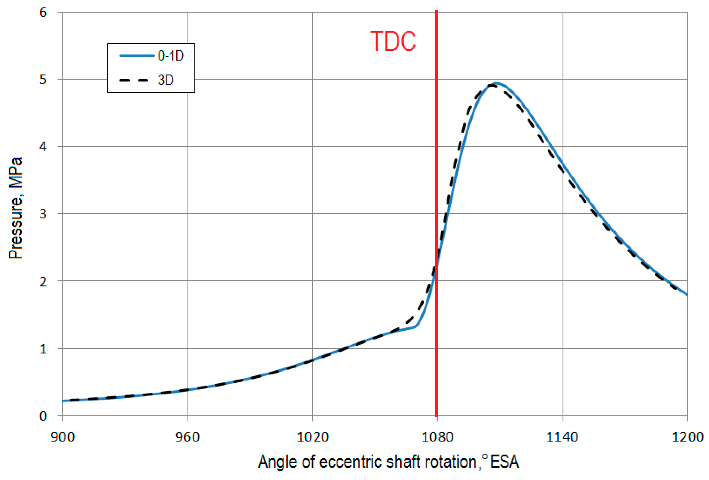
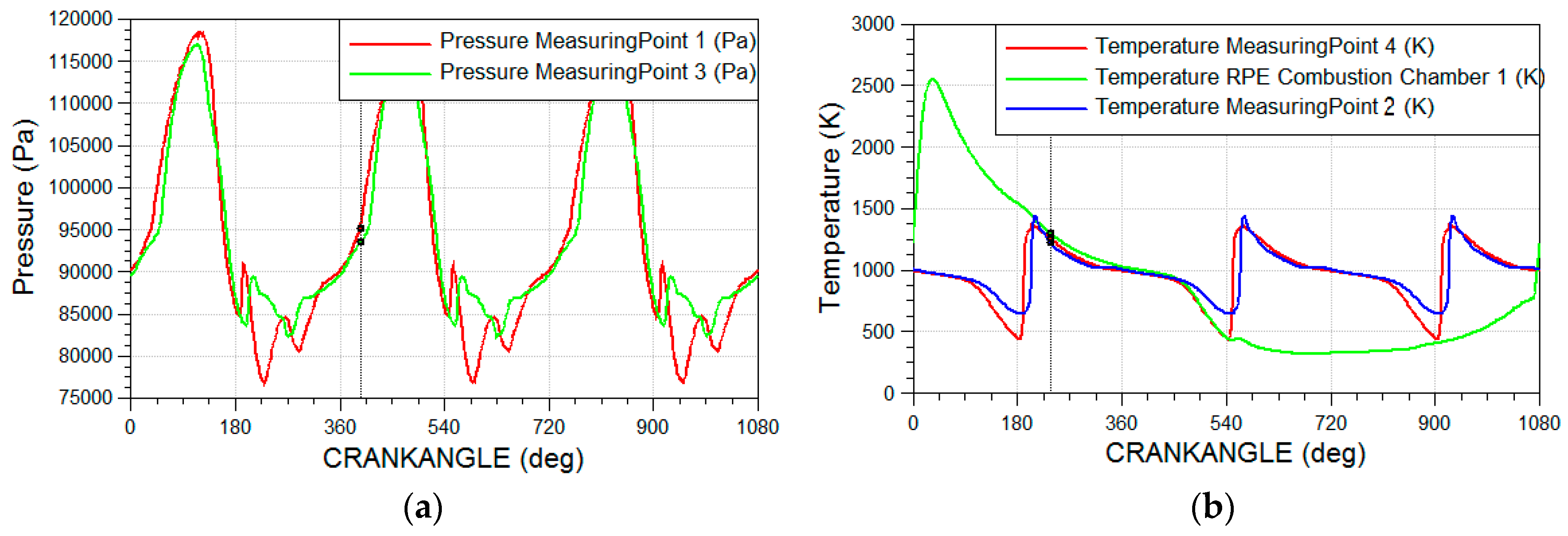
The dependence of pressure and temperature—as well as heat generation rates and the amount of heat given to parts of the WE combustion chamber—on the angle of rotation of the eccentric shaft (obtained as a result of a three-dimensional calculation of the WE workflow) allowed us to estimate its effective performance and predict the level of thermal load on the main parts of the engine.

3.1. Validation

For a preliminary assessment of the correctness of the three-dimensional calculation results, a 1D-model—the scheme of which is given in Figure 3—was used.
During verification, a comparison of indicator diagrams was conducted (Figure 4), and this showed a satisfactory reconciliation of the calculated data (in this case, the error in the maximum pressure pz did not exceed 0.5%, and the angle of its achievement was less than 1%).
The discrepancy between the indicator diagrams at the moment of the start of heat generation when the spark plugs are triggered is explained by the difference in the configuration of the combustion chamber of the Wankel engine from the traditional piston-type one with spark ignition: The WE combustion chamber is characterized by relatively large longitudinal dimensions with small transverse dimensions, which slows the spread of the flame front. In addition, it is necessary to take into account the presence of two spark plugs, which is difficult in a 1D-model.
In the future, it is also planned to use experimental data as a criterion for the adequacy of the three-dimensional model.
Based on a comparison of the available results of 1D and 3D calculations, it can be concluded that the 3D CFD model of the workflow process of the perspective aviation Wankel engine adequately describes the real thermophysical processes in the estimated volume and can be used for further engine research. As a strand of research, the determination of the influence of the WE design parameters (such as the shape of the combustion chamber (recess) in the rotor and the arrangement of spark plugs) on the engine performance can be chosen. It is also possible to use the developed model to analyze the influence of various moments of spark plugs operation on the workflow.

3.2. Results of Numerical Experiments

As the boundary conditions for three-dimensional calculation, the pressures and temperatures of gas at the engine inlet and outlet, previously calculated according to the 1D model (Figure 5a,b), were assigned. Wall temperatures for the inlet and outlet ports, as well as the rotor, stator, side covers (heads) were set as follows: Twrotor = 553 K, Twstator (depending on the angle of eccentric shaft rotation) from 393 K (inlet) to 530 K (combustion zone and exhaust), and Twheads = 393 K (inlet)–470 K (combustion zone and exhaust).
In the WE section, the inlet and exhaust ports initial conditions (pressure p0, temperature T0) were also set according to the results of 1D calculation. The initial value of turbulent kinetic energy k0 = 5 m2/s2, and turbulence length scale TLS0 = 0.001 m
As a result of the calculation, the values of temperature, pressure, and velocities of the working fluid in the cross-sections of the WE working chamber were obtained both for the processes of exhaust, scavenging, filling of the working chamber (Figure 6a–c), and combustion of the fuel-air mixture (Figure 7a–d).
It is worth noting that in traditional piston engines, an increase in the efficiency of the combustion of the air–fuel mixture, as well as a reduction in emissions of harmful substances, can be achieved by profiling the intake ports and the combustion chamber [20,21,22]. In a Wankel engine, the effect of flow swirl at the inlet is less noticeable due to the characteristic shape of the combustion chamber, which, by the time the rotor reaches the TDC (top dead center, the point of the minimum combustion chamber volume), is strongly deformed in the radial direction. As a result, at this time, the shape of the recess in the rotor has a major impact on the rotational flows in the CC instead of the shape of the intake and exhaust ports.
It is noticeable that when the spark plugs are simultaneously actuated (the spark angle is 1046° ESA, i.e., 34° ESA to TDC), there is a significant irregularity of flame propagation in the direction of rotor movement (in Figure 6, the rotor moves counterclockwise). This fact indicates the need to introduce different spark angles for the two plugs, with a later ignition of the trailing one (the interval between spark plug actuation is 15° ESA).
An alternative way of influencing the nature of the flame front propagation over the WE working chamber is to modify the shape of the chamber (recess) in the rotor. According to the results of numerical simulation, a modification of the rotor design was offered, with a recess of variable depth expanding in the direction of the rotor movement (Figure 8b).
Unlike the basic shape of the recess (Figure 8a), the offered modification provides for better access of the combustion products to the peripheral regions of the CC, which allows for a more uniform distribution of local temperature fields in the volume of the combustion chamber of the Wankel engine, increasing its efficiency while reducing maximum temperature values (Figure 9). As a result, there is an increase in the maximum pressure values in the WE working chamber (Figure 10), and its power indices increase. It is noticeable that the modified combustion chamber provides a smoother increase in the heat release rate at the initial stage (until the TDC = 1080° ESA) at a slightly higher maximum value at a subsequent stage (99 J/deg for the modified chamber and 86 J/deg for the base form; Figure 11).
Lower maximum gas temperatures (Tmax = 2821 K for modified CC and 2967 K for base CC) lead to a 42% improvement in the engine’s environmental indexes of nitrogen oxide (NOx) emissions and an increase in its efficiency in regard to the reduction of carbon dioxide (CO2) emissions (by 5%) (Figure 12a,b). It should be noted that today there are no restrictions on NOx and CO2 emissions for aircraft piston engines, which is primarily due to the relatively small number of aircraft equipped with such power units [23,24]. However, since the tendency to strengthen environmental requirements leads to the possibility of such restrictions in the future, they should be taken into account when designing new engine units. From this point of view, the offered combustion chamber looks promising, since it allows for the reduction of both NOx and CO2 emissions.
For a further improvement of the rotor chamber design, it is also planned to reduce the angle of the inclination of the recess walls relative to the working surface of the rotor in order to minimize separated flows.

4. Conclusions

  • A mathematical model of the Wankel engine has been developed, one which allows three-dimensional determining of the parameters of the working fluid in the entire calculated volume, taking into account inlet and exhaust processes. This model also takes into account the geometric features of the WE combustion chamber and allows for the determination of the best design in terms of improving the engine efficiency.
  • A later ignition of the trailing spark plug was proposed (the interval between spark plug actuation is 15 °ESA), which reduced the irregularity of flame propagation in the direction of the rotor movement.
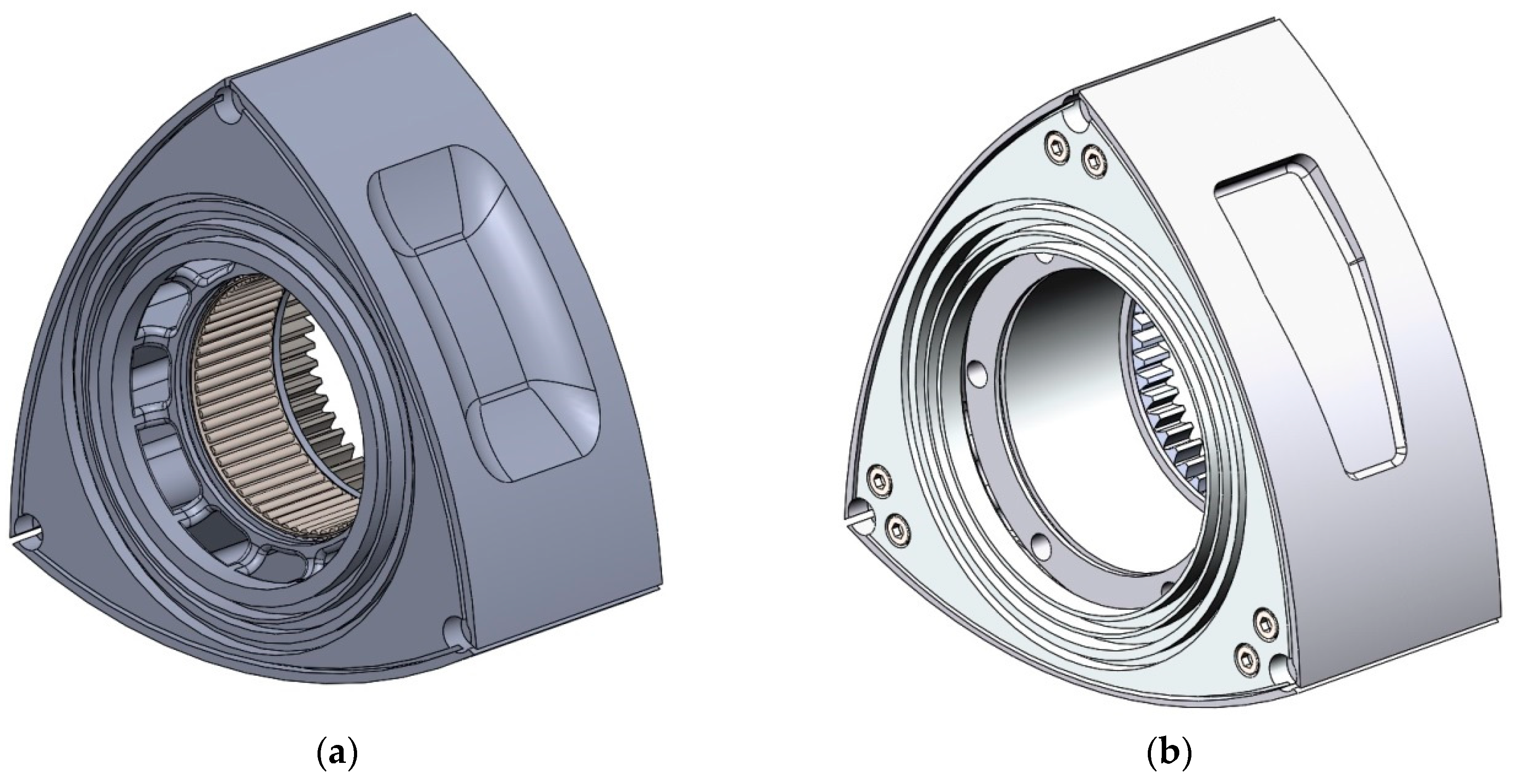
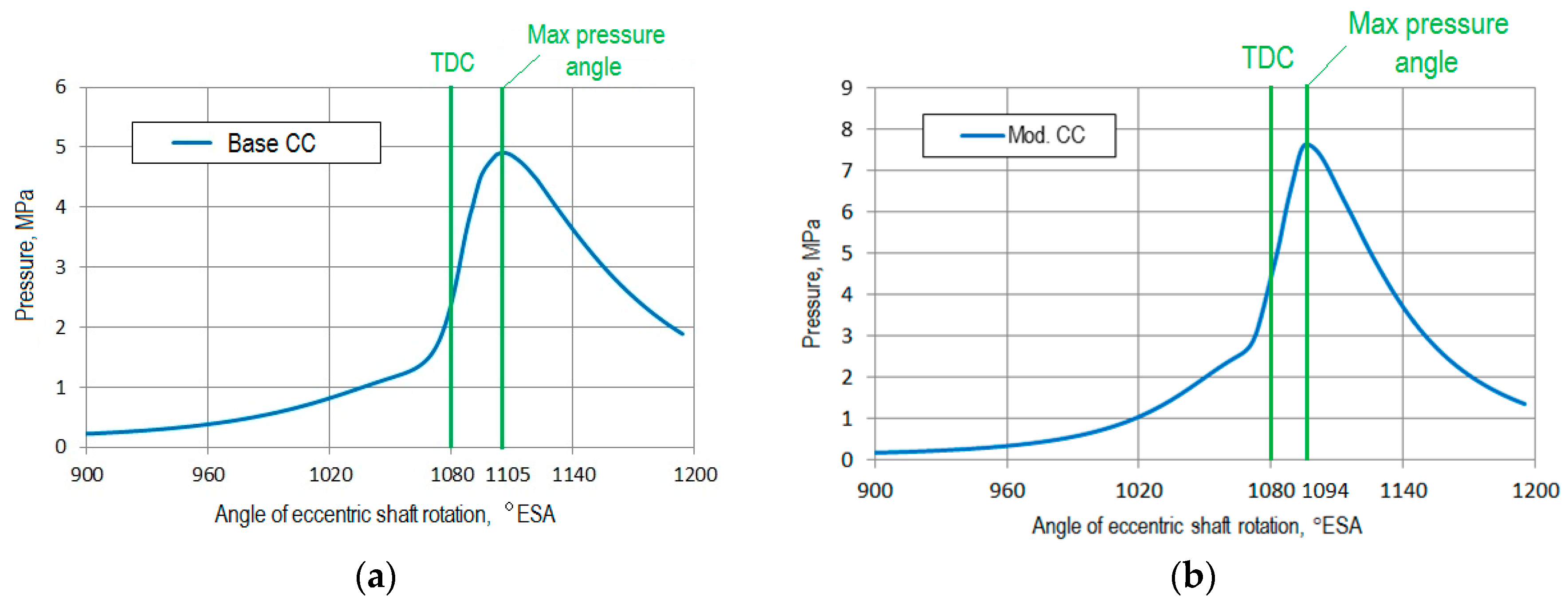
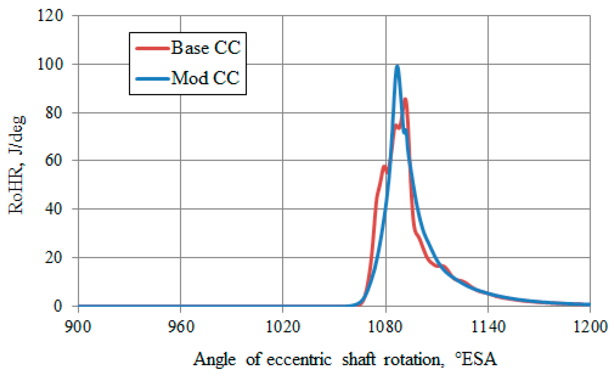
  • According to the results of modeling the processes of turbulent combustion and transfer in the WE working chamber, a significant influence of the shape of the recess in the rotor on the engine performance has been determined. An alternative design of the chamber shape in the rotor, which allows increasing the efficiency of the WE operation, has been offered.
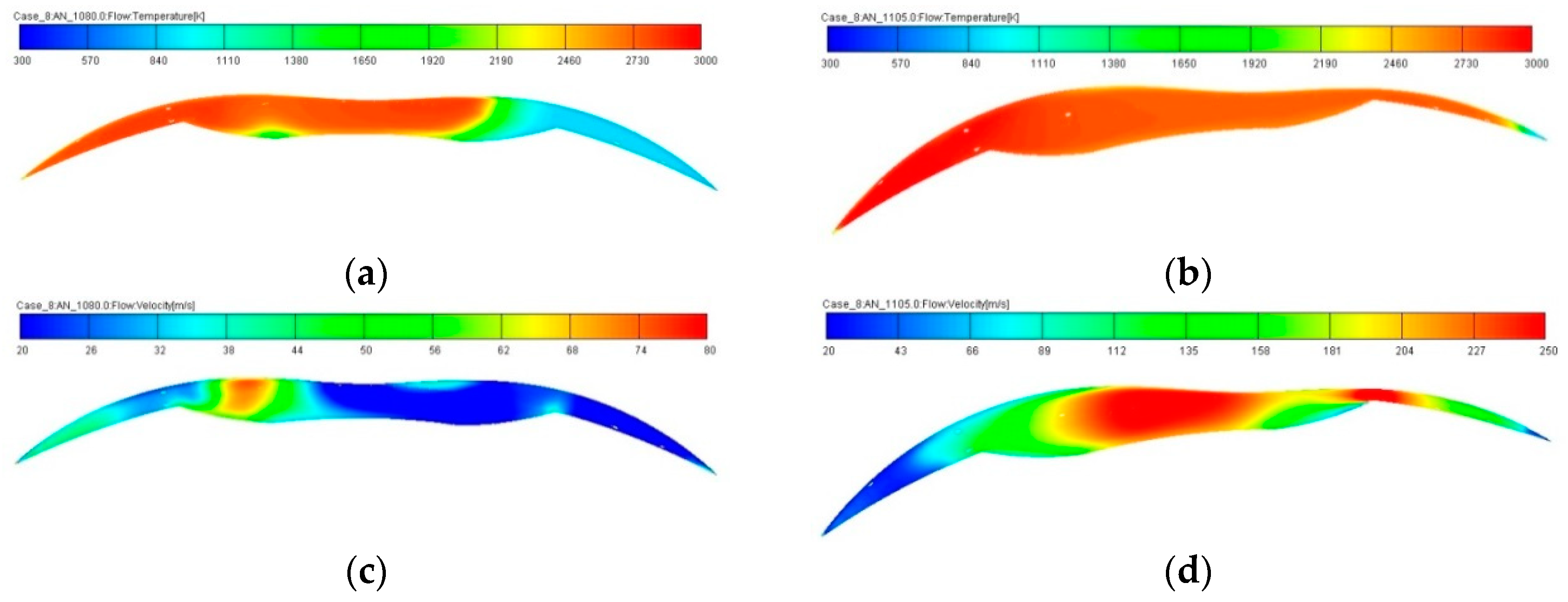
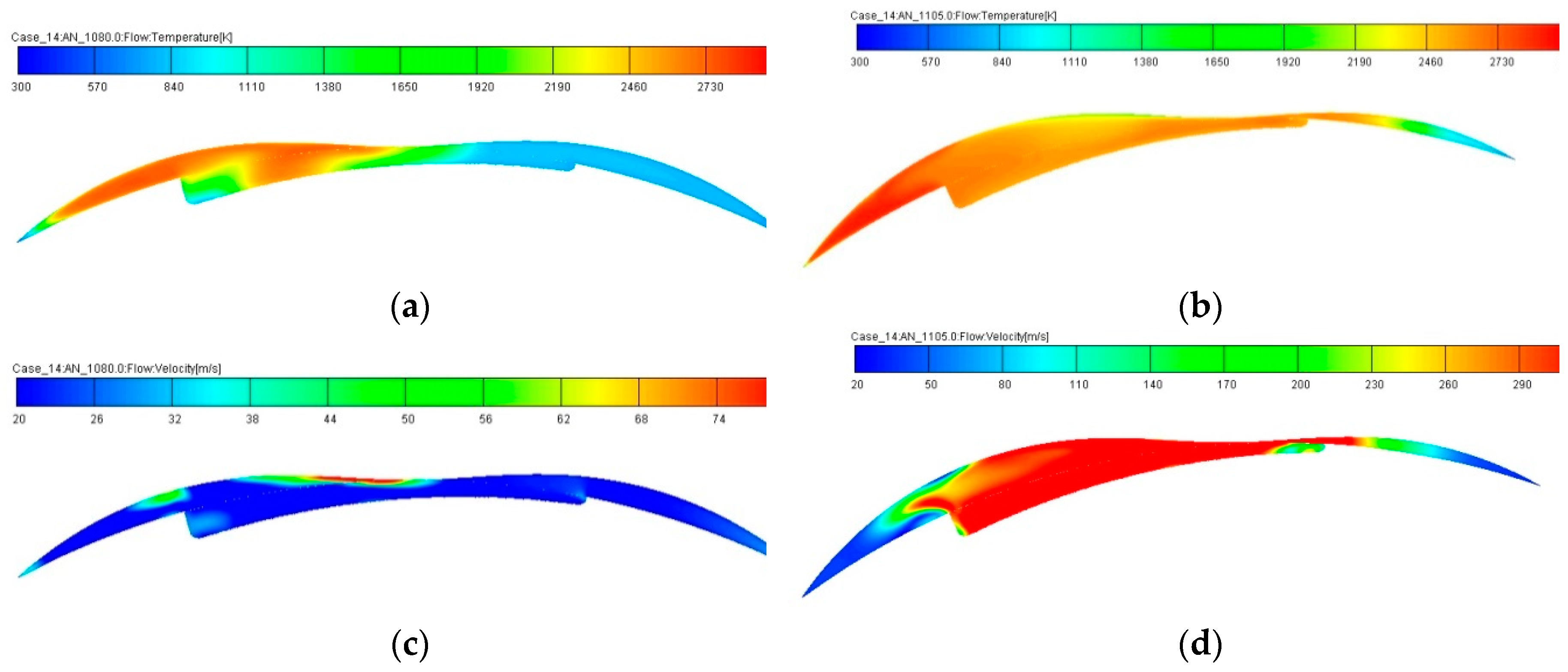
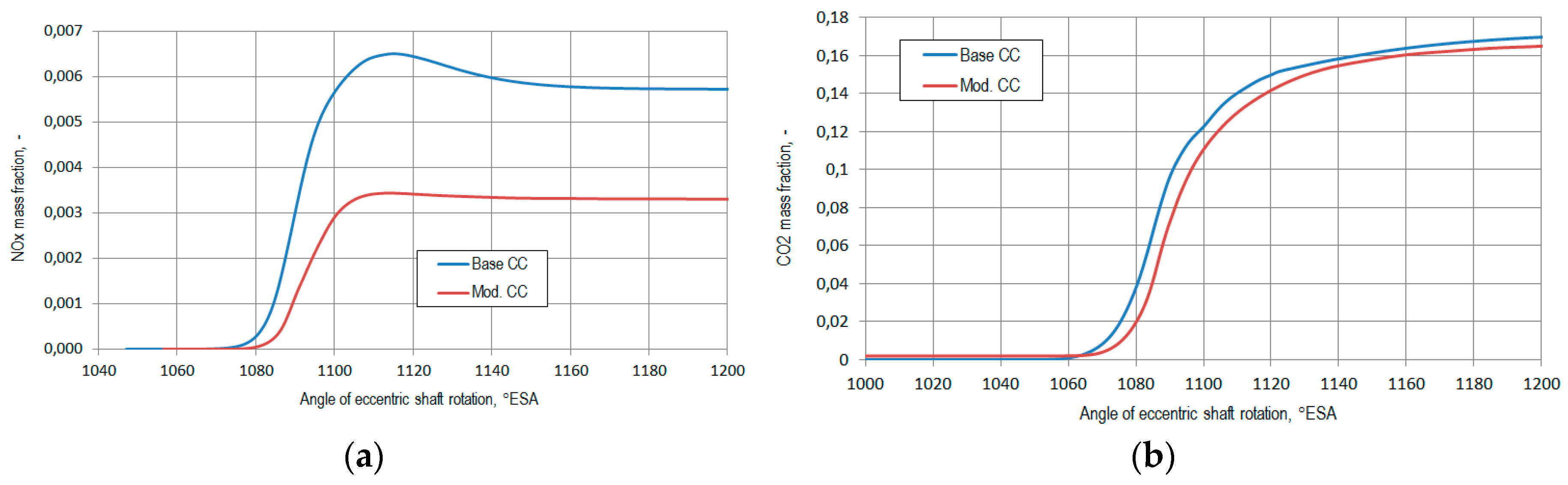
  • It has been shown that lower values of maximum gas temperature (Tmax = 2821 K for modified CC and 2967 K for base CC) lead to 42% improvement in the engine environmental performance of nitrogen oxide (NOx) emissions and an increase in its efficiency in regard to the reduction of carbon dioxide (CO2) emissions (by 5%).

Author Contributions

Conceptualization, L.F. and A.K.; Methodology, A.K. and A.Z.; Validation, A.Z. and V.M.; Formal Analysis, A.K. and A.Z.; Investigation, A.Z.; Resources, L.F.; Writing—Original Draft Preparation, A.Z.; Writing – Review & Editing, A.K.; Visualization, A.Z.; Supervision, L.F.; Project Administration, L.F.

Funding

This research received no external funding.

Acknowledgments

The authors would like to express sincere gratitude to the Researcher Links program of the British Council for the financial support of this publication.

Conflicts of Interest

The authors declare no conflict of interest.

References

  1. Stone, R. Introduction to Internal Combustion Engines, 4th ed.; Palgrave Macmillan Press: Basingstoke, UK, 2012; 516p. [Google Scholar]
  2. The New Generation of Wankel Rotary Engines; Wankel Super-Tec GmbH: Cottbus, Germany, 2004; p. 30.
  3. Kostyuchenkov, A.N.; Zelentsov, A.A.; Semenov, P.V.; Minin, V.P. Development of a Single-Section Demonstrator Rotary Engine on the Basis of a Modern Complex Design Procedure. Vestn. Samara Gos. Aerocosm. Univ. 2014, 2, 173–181. (In Russian) [Google Scholar] [CrossRef]
  4. Beniovich, V.S.; Apazidi, G.D.; Boyko, A.M. Rotary Engines; Mashinostroenie Publ.: Moscow, Russia, 1968; p. 153. (In Russian) [Google Scholar]
  5. Yamamoto, K. Rotary Engine; Sankaido Co., Ltd.: Tokyo, Japan, 1981; p. 68. [Google Scholar]
  6. Poojitganont, T.; Izweik, H.T.; Berg, H.P. The Simulation of Flow Field inside the Wankel Combustion Chamber. In Proceedings of the 20th Conference of Mechanical Engineering Network, Nakhon Ratchasima, Thailand, 18–20 October 2006. [Google Scholar]
  7. Kavtaradze, R.Z. Theory of Piston Engines: Special Chapters; Mosk. Gos. Tekh. Univ. im. N.E. Baumana: Moscow, Russia, 2016; pp. 467–496. (In Russian) [Google Scholar]
  8. Kavtaradze, R.Z. Three-Dimensional Simulation of Non-steady Thermophysical Processes in Piston Engines; Mosk. Gos. Tekh. Univ. im. N.E. Baumana: Moscow, Russia, 2012; pp. 5–33. (In Russian) [Google Scholar]
  9. Merker, G.; Schwarz, C.; Teichmann, R. Grundlagen Verbrennungsmotoren: Funktionsweise, Simulation, Messtechnik (Fundamentals of Internal Combustion Engines: Mode of Operation, Simulation, Measurement Technology), 9th ed.; Springer: Wiesbaden, Germany, 2019; p. 1117. [Google Scholar]
  10. Basshuysen, R.; Schäfer, F. (Hrsg.) Handbuch Verbrennungsmotor. 4. Auflage; Vieweg und Sohn Verlag: Wiesbaden, Germany, 2007; p. 1032. [Google Scholar]
  11. Kavtaradze, R.; Zelentsov, A.; Gladyshev, S.P.; Kavtaradze, Z.; Onishchenko, D. Heat insulating effect of soot deposit on local transient heat transfer in diesel engine combustion chamber. SAE Int. Pap. 2012. [Google Scholar] [CrossRef]
  12. Kavtaradze, R.Z. Local Heat Transfer in Piston Engines; Mosk. Gos. Tekh. Univ. im. N.E. Baumana: Moscow, Russia, 2016; pp. 189–226. (In Russian) [Google Scholar]
  13. Tatschl, R.; Schneider, J.; Basara, D.; Brohmer, A.; Mehring, A.; Hanjalić, K. Progress in the 3D-CFD calculation of the gas and water side heat transfer in engines, in Verfahren 10 Tagung der Arbeitsprozess des Verbrennungsmotors. In Proceedings of the 10th Meeting on the Working Process of the Internal Combustion Engine, Graz, Austria, 23–25 September 2005. [Google Scholar]
  14. Hanjalić, K.; Popovać, M.; Hadziabdić, M. A Robust Near-Wall Elliptic-Relaxation Eddy-Viscosity Turbulence Model for CFD. Int. J. Heat Fluid Flow 2004, 25, 897–901. [Google Scholar] [CrossRef]
  15. Tatschl, R.; Basara, B.; Schneider, J.; Hanjalic, K.; Popovac, M.; Brohmer, A.; Mehring, J. Advanced Turbulent Heat Transfer Modeling for IC-Engine Applications Using AVL FIRE. In Proceedings of the International Multidimensional Engine Modeling User’s Group Meeting, Detroit, MI, USA, 2 April 2006. [Google Scholar]
  16. Popovać, M.; Hanjalić, K. Compound Wall Treatment for RANS Computation of Complex Turbulent Flow. In Proceedings of the 3rd M.I.T. Conference, Boston, MA, USA, 14–17 June 2005. [Google Scholar]
  17. Candel, S.; Poinsot, T. Flame Stretch and the Balance Equation for the Flame Area. Combust. Sci. Technol. 1990, 70, 1–15. [Google Scholar] [CrossRef]
  18. Delhaye, B.; Cousyn, B. Computation of Flow and Combustion in Spark Ignition Engine and Comparison with Experiment. SAE Technol. Pap. 1996, 961960. [Google Scholar] [CrossRef]
  19. Meneveau, C.; Sreenivasan, K.R. The Multifractal Nature of Turbulent Energy Dissipation. J. Fluid Mech. 1991, 224, 429–484. [Google Scholar] [CrossRef]
  20. Kavtaradze, R.Z.; Onishchenko, D.O.; Zelentsov, A.A.; Sergeev, S.S. The influence of rotational charge motion intensity on nitric oxide formation in gas-engine cylinder. Int. J. Heat Mass Transf. 2009, 52, 4308–4316. [Google Scholar] [CrossRef]
  21. Kavtaradze, R.Z.; Onishchenko, D.O.; Golosov, A.S. Modeling of Processes into the Intake System of Aircraft Piston Engine with Intake Port Injection. Vestn. Mosk. Gos. Tekh. Univ. im. N.E. Baumana. Mashinostr. [Herald of the Bauman Moscow State Technical Univ. Mech. Eng. 2012, 4, 3–16. (In Russian) [Google Scholar]
  22. Lanshin, A.I.; Finkelberg, L.A.; Kostuchenkov, A.N.; Zelentsov, A.A.; Bakanov, M.A. Investigation of Inlet Flow Swirl Influence on the Aviation Piston Engine Characteristics. Vestn. Voronezh Gos. Tekh. Univ. [Herald of Voronezh State Technical Univ.] 2012, 2, 96–99. (In Russian). Available online: https://elibrary.ru/item.asp?id=17335022 (accessed on 14 June 2019).
  23. Zelentsov, A.A. Analysis of Influence of Working Process Features on Effective Characteristics of Aircraft Piston Engines. Vestn. Mosk. Gos. Tekh. Univ. im. N.E. Baumana. Mashinostr. [Herald of the Bauman Moscow State Technol. Univ., Mech. Eng.] 2013, 4, 81–93. (In Russian). Available online: http://vestnikmach.ru/articles/177/177.pdf (accessed on 14 June 2019).
  24. Kavtaradze, Z.; Onishchenko, D.O.; Zelentsov, L.A.; Finkel’berg, L.A.; Kostyuchenkov, A. Modeling of Processes of Transfer, Combustion and Nitric Oxides Formation in the Aircraft Piston Engine with Duplicated Ignition System. Izv. Akad. Nauk. Energetik 2012, 6, 135–152. (In Russian) [Google Scholar]
Figure 1. 3D model of developed Wankel engine: (a) Ready-assembled; (b) rotor-stator assembly.
Energies 12 02292 g001
Figure 2. Combustion chamber of the Wankel engine (a) and control volume mesh (b).
Energies 12 02292 g002
Figure 3. Design model for the single-section Wankel engine (WE): 1: Unit that sets operating parameters of the engine; 2: Block simulating the WE section; 3 and 4: Boundary conditions definition; 5 and 6: Restrictions; 7 and 8: Measuring points; 9: Injector; 10: Throttle; 11: Intake pipes; 12: Exhaust pipes.
Energies 12 02292 g003
Figure 4. Model verification—comparison of the indicator diagrams of the Wankel engine in case of 1D and 3D calculations.
Energies 12 02292 g004
Figure 5. Boundary conditions for the subsequent 3D calculation of the working process: (a) Pressure; (b) gas temperatures in measuring points.
Energies 12 02292 g005
Figure 6. Calculation results for exhaust (a), scavenging of the combustion chamber (b), and intake (c) processes in Wankel engine.
Energies 12 02292 g006
Figure 7. Temperature—(a) and (b)—and velocity values—(c) and (d)—in cross-section of the base WE combustion chamber. (a) and (c): Rotor position in top dead center (φ = 1080° ESA); (b) and (d): Maximum pressure angle position of rotor (φ = 1105° ESA).
Energies 12 02292 g007
Figure 8. WE rotor variants: (a) Base; (b) modified.
Energies 12 02292 g008
Figure 9. Temperature—(a) and (b)—and velocity values—(c) and (d)—in a cross-section of a modified WE combustion chamber. (a) and (c): Rotor position in top dead center (φ = 1080 °ESA); (b) and (d): Maximum pressure angle position of rotor (φ = 1105 °ESA).
Energies 12 02292 g009
Figure 10. Indicator diagram of a WE with a base (a) and modified (b) combustion chamber.
Energies 12 02292 g010
Figure 11. Rate of heat release in base and modified combustion chambers of a WE.
Energies 12 02292 g011
Figure 12. NOx (a) and CO2 (b) mass fractions in base and modified WE combustion chambers.
Energies 12 02292 g012

