Article

Model-Based Pre-Ignition Diagnostics in a Race Car Application

1
Department of Industrial Engineering, University of Bologna, via Seganti 103, 47121 Forli, Italy
2
Scuderia Ferrari, Via Enzo Ferrari 27, 41053 Maranello, Italy
*
Author to whom correspondence should be addressed.
Energies 2019, 12(12), 2277; https://doi.org/10.3390/en12122277
Submission received: 12 May 2019 / Revised: 7 June 2019 / Accepted: 12 June 2019 / Published: 14 June 2019

Abstract

:
Since 2014, Formula 1 engines have been turbocharged spark-ignited engines. In this scenario, the maximum engine power available in full-load conditions can be achieved only by optimizing combustion phasing within the cycle, i.e., by advancing the center of combustion until the limit established by the occurrence of abnormal combustion. High in-cylinder pressure peaks and the possible occurrence of knocking combustion significantly increase the heat transfer to the walls and might generate hot spots inside the combustion chamber. This work presents a methodology suitable to properly diagnose and control the occurrence of pre-ignition events that emanate from hot spots. The methodology is based on a control-oriented model of the ignition delay, which is compared to the actual ignition delay calculated from the real-time processing of the in-cylinder pressure trace. When the measured ignition delay becomes significantly smaller than that modeled, it means that ignition has been activated by a hot spot instead of the spark plug. In this case, the presented approach, implemented in the electronic control unit (ECU) that manages the whole hybrid power unit, detects a pre-ignition event and corrects the injection pattern to avoid the occurrence of further abnormal combustion.

1. Introduction

To promote research and development in the field of internal combustion engines, the Federation International de l’Automobile (FIA) has recently revised the Formula 1 sporting regulations [1,2]. As a result, since 2014, the spark-ignited internal combustion engine (ICE) has been downsized to a 1.6 L engine with a V6 layout. The engine is turbocharged with a single-stage turbocharger, and the maximum available power is limited through the limitation of the instantaneous fuel mass flow to 100 kg/h. The discussed engine layout is also characteristic of modern spark-ignition (SI) engines, where downsizing and supercharging are the means to achieve high performance and reduced fuel consumption [3].
In SI engines, standard combustion is activated by an electrically induced spark and characterized by uniform flame propagation throughout the combustion chamber. However, downsizing and boosting usually result in higher in-cylinder pressures and temperature, which potentially lead to uncontrolled spontaneous ignitions [4,5,6,7,8]. The abnormal combustion processes can be divided into two main mechanisms: end-gas auto-ignition (end-gas knock due to high pressure and temperature) and surface ignition (pre-ignition due to hot spots inside the combustion chamber) [8]. Both mechanisms result in uncontrolled combustion, characterized by impulsive energy releases and high-pressure peaks, which might lead to engine degradation and failure. Even though the mechanisms might have similar consequences for the engine and be present together, the strategies used to diagnose their occurrence need to be significantly different. In spark-ignited engines (both for standard and motorsport applications), end-gas knock is successfully controlled through proper spark advance/retarding (except in the case of runaway knock [9,10,11]), which reduce pressure and temperature during the combustion process. To maximize engine power and avoid reliability issues, an accurate cycle-by-cycle knock detection strategy is necessary; this can be based on the analysis of several kinds of signals, such as in-cylinder pressure (often used as a reference for the calibration of detection strategies) [12], engine block acceleration [13], ion currents [14], acoustic emissions [15,16], or innovative low-cost piezo-electric sensing devices [17]. Once the occurrence of end-gas knock has been detected, a specific control strategy needs to manage the proper spark advance reductions to avoid the risk of engine damage (retarding the combustion process within the cycle) [14].
The proper management of pre-ignition events is less straightforward than the control of end-gas knock because pre-ignitions are activated by hot spots already present during the compression stroke. As a result, reducing spark advance is not always the proper action to avoid further pre-ignition events because pressure and temperature in correspondence to the spark angle would be even higher. For the above reasons, it is extremely important to set up a reliable strategy to distinguish between one abnormal combustion mechanism and the other; otherwise, it would be difficult to activate the optimal control strategy.
This work presents a model-based strategy (implemented in the electronic control unit (ECU)) used to detect pre-ignition events and avoid further consecutive occurrences in all Ferrari Formula 1 engines. Pre-ignition detection is based on a control-oriented ignition delay model [18,19]. A comparison between the modeled ignition delay and measured ignition delay, calculated in real time from in-cylinder pressure measurements, allows detection of the pre-igniting cycles, i.e., the ones characterized by a measured ignition delay much lower than the expected value. To prove the accuracy of the ignition delay model, the estimated values are compared to the ignition delay values measured during standard operating cycles.
Once the pre-igniting cycles have been identified, the controller performs a proper reduction of the injected amount of fuel, the goal being to immediately reduce the temperature of the hot spots and avoid consecutive abnormal combustions. As a matter of fact, both experiments and the literature confirm that abnormal ignitions by one source can induce abnormal ignitions by the other [3]. As an example, a pre-ignition due to a hot spot can result in increased heat transfer to the piston (increasing the local temperature) and result in end-gas knock in the following cycles. For this reason, the controller needs to react immediately after the detection and perform a fuel reduction compatible with the intensity and frequency of the abnormal combustion detected.
The presented strategy for the detection and control of pre-ignition events is currently implemented in the control strategy of all Ferrari engines used for Formula 1 applications, i.e., used by Ferrari and supplied to its customer teams. However, the discussed approach is methodological and could also be applied to standard spark-ignited engines (with different architectures) used in common automotive applications.

2. Methodology for Pre-Ignition Detection

The whole methodology discussed in this paper was developed to control and limit the occurrence of pre-ignition events in real time in the engine under investigation (Ferrari V6 engine) when installed on board the vehicle. To do so, both the analysis and the implementation were carried out using only the signals available on board the Formula 1 car. In particular, Ferrari engines are always equipped with one piezo-electric in-cylinder pressure sensor per cylinder (the model is not disclosed due to confidentiality reasons). The cylinder pressure signals are processed in real time by a specific indicating system that calculates the combustion indices of interest and provides the calculated quantities to the standard ECU used for engine control (McLaren TAG 320). As a result, the engine control strategy can perform a closed-loop correction of ignition and injection based on the combustion feedback from the previous cycles.

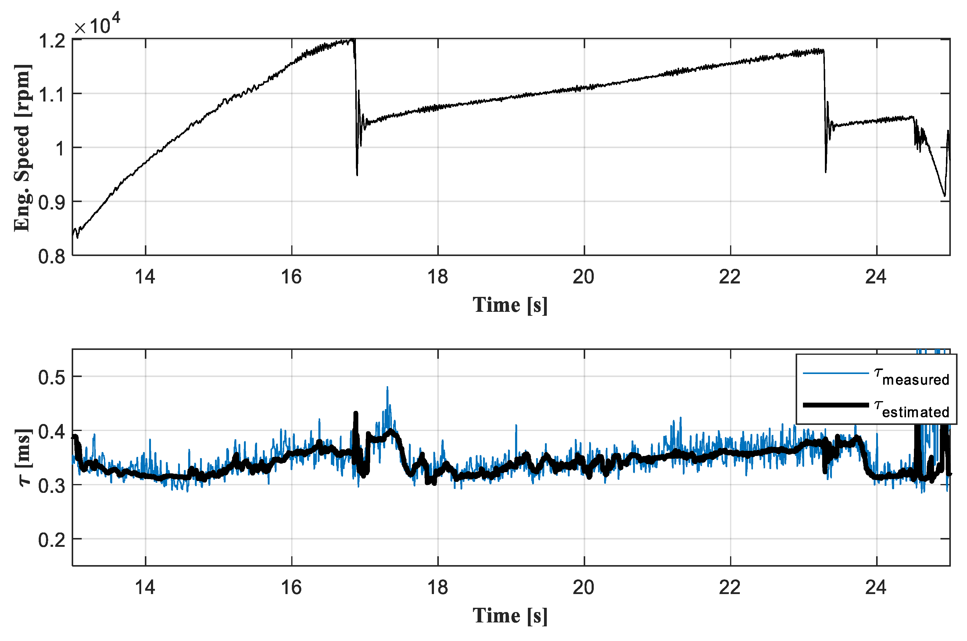
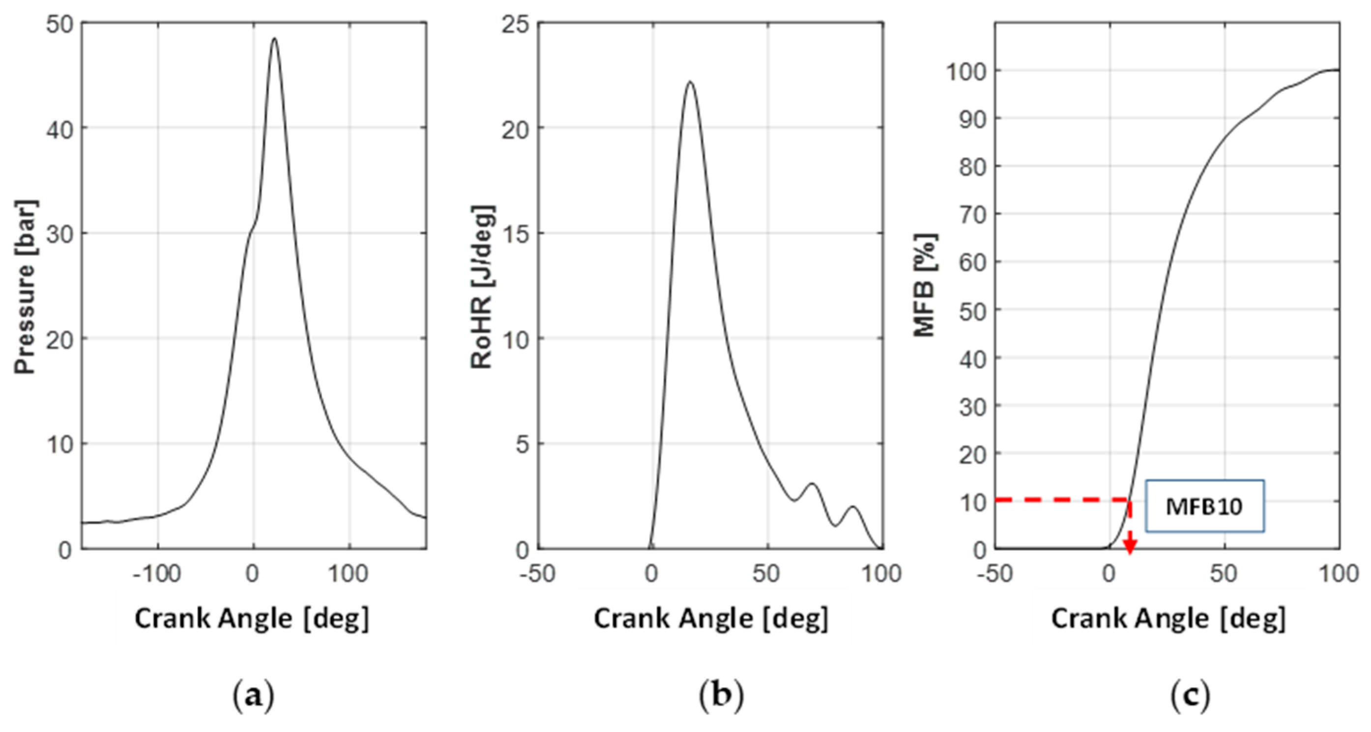
2.1. Calculation of the Measured Ignition Delay

In this application, cylinder pressure measurements are used to determine the measured ignition delay ( τ m ), calculated as the time corresponding to the angular distance between the spark angle (SA, mapped in the ECU) and the angular position at which 10% of fuel burned within the engine cycle is reached (MFB10, calculated by the indicating system and sent to the ECU via controller area network (CAN) bus). The MFB10 calculation is performed by detecting the angular position corresponding to 10% of the accumulated apparent rate of heat release (RoHR), determined through Equation (1) [20], where γ is the specific heat ratio of the gas, θ is the crankshaft angle, and p and V represent the in-cylinder pressure and volume, respectively.
RoHR = γ γ 1 p d V d θ + 1 γ 1 p d p d θ
The calculated RoHR is integrated in a proper angular window around the top dead center (TDC) and normalized with respect to its maximum value. The angular position corresponding to 10% of this normalized curve, usually termed the mass fraction burned amount (MFB), is the measured MFB10, which represents a robust approximation of the start of combustion. To clarify the above considerations, Figure 1 reports the main quantities used for MFB10 calculation, i.e., the in-cylinder pressure (a), RoHR (b), and MFB (c).
Once MFB10 has been calculated by the indicating system and transmitted to the ECU, the measured ignition delay (expressed in milliseconds) can be easily calculated by the engine control strategy using Equation (2).
τ m [ m s ] = S A [ deg B T D C ] M F B 10 [ deg A T D C ] n E n g i n e   [ r p m ] · 1000 6
Here, the values of both SA and MFB10 are considered positive before (BTDC) and negative after the TDC (ATDC), while nEngine is the engine rotational speed in rpm. It is important to highlight that the ECU receives the calculated MFB10 before the end of the current engine cycle. Consequently, if the occurrence of an abnormal combustion is detected (based on the calculated value of τ m ), the engine controller can put into practice a correction of the control parameters (injected fuel or spark advance) from the first cycle following the abnormal combustion.

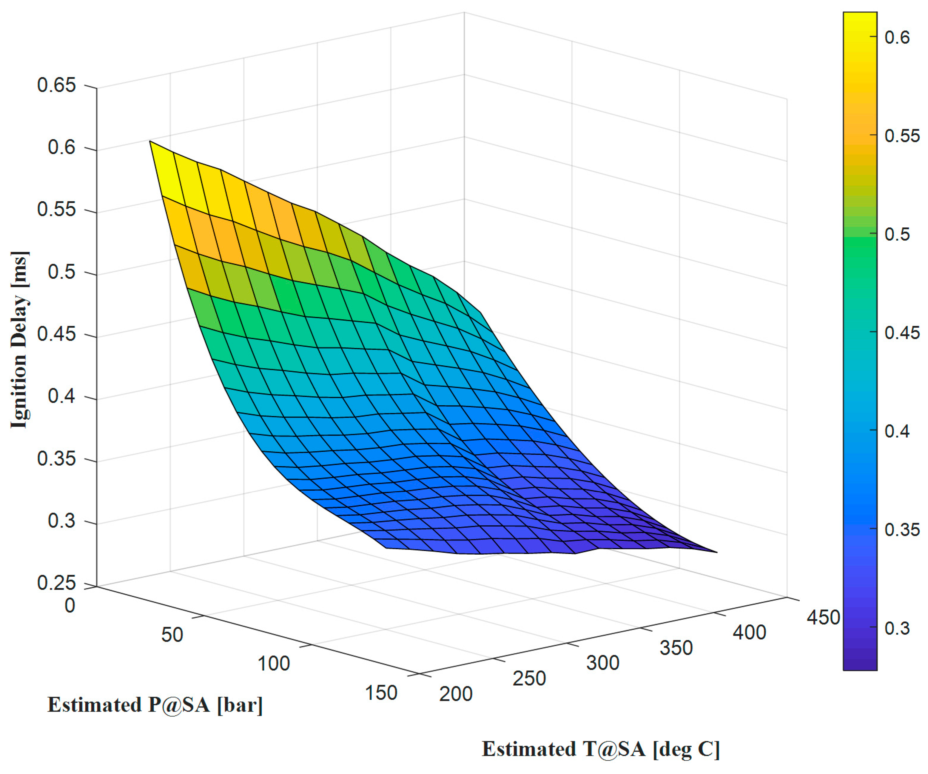
2.2. Control-Oriented Model of the Ignition Delay

Once the measured ignition delay ( τ m ), calculated as mentioned in the previous subsection, is available to the engine controller, comparison with the expected ignition delay for a standard combustion process allows the detection of pre-igniting cycles. As a matter of fact, in the case of standard combustion events, ignition is activated by the spark plug and propagates as a turbulent flame front throughout the combustion chamber.
According to Equation (3) [20], for a given fuel the ignition delay can be strongly influenced by several factors, such as the in-cylinder pressure (p), in-cylinder temperature (T), and the air-to-fuel ratio (here, A, n, and B are fitted parameters that depend on the fuel and air–fuel ratio [21]).
τ = A · p n · e B T
If the measured ignition delay becomes significantly smaller than the delay that is predicted for the current operating conditions, a pre-ignition event is occurring.
In this work, the expected ignition delay of the air–gasoline mixture is calculated through a specifically designed control-oriented model that captures the main dependencies with respect to
  • The in-cylinder temperature corresponding to the spark advance (SA);
  • The in-cylinder pressure corresponding to the SA; and
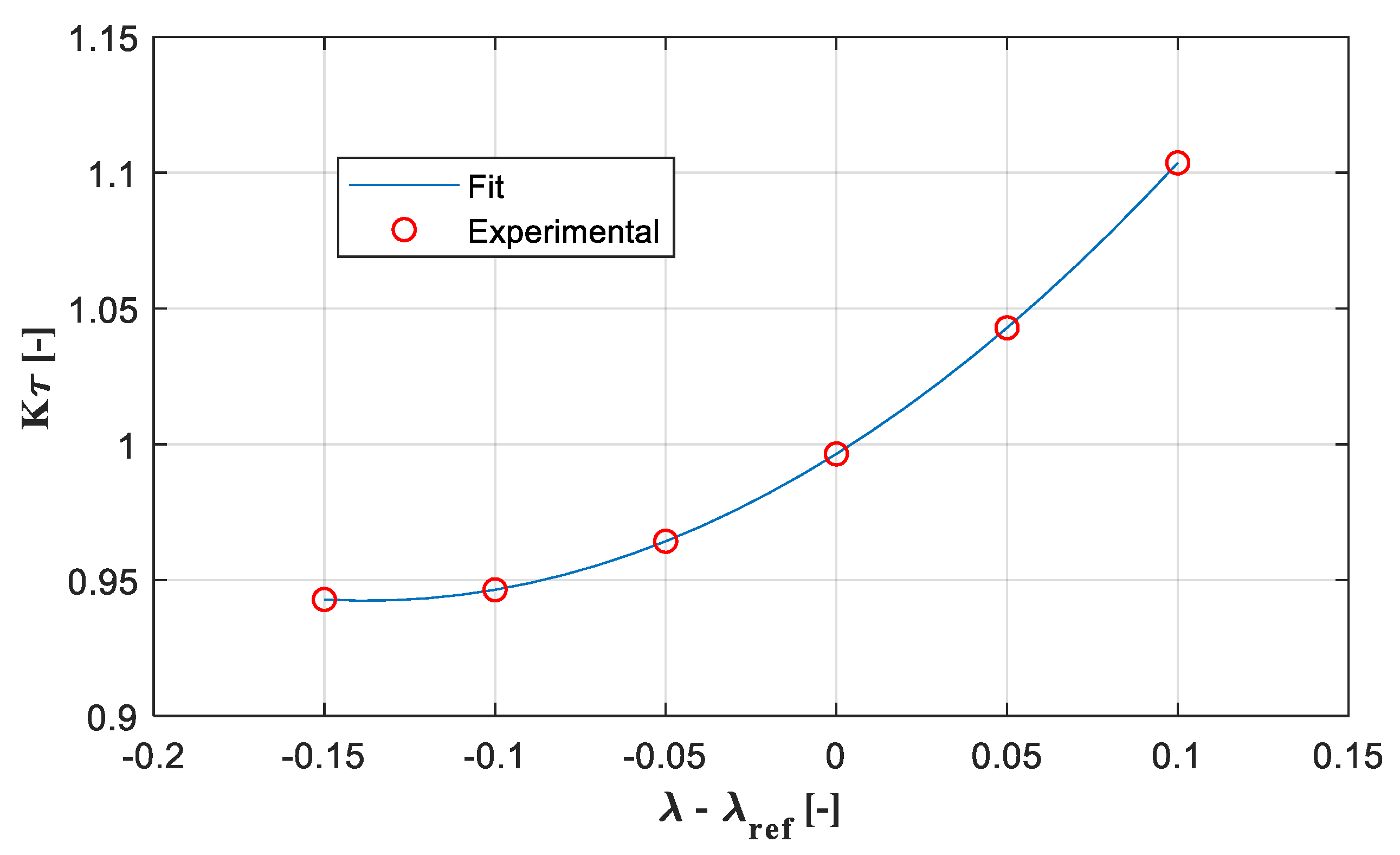
  • The air-to-fuel ratio (estimated in real time by the engine control strategy).
Even though direct measurement of the cylinder pressure corresponding to the spark advance would be possible (the engine is equipped with one sensor per cylinder), measuring the corresponding temperature would be extremely critical; this is mainly due to the slow dynamic temperature sensors which are not compatible with the fast dynamics occurring during an engine cycle. This problem can be easily overcome by simply considering that the compression stroke can be accurately approximated using a polytropic transformation, i.e., the pressure (p) and temperature (T) can be calculated by simply rearranging Equation (4), where V is the in-cylinder volume and γ is the specific heat ratio ( γ = c p / c v ).
p V γ = c o n s t .
Here, p and V are the in-cylinder pressure and volume, respectively, while γ is the specific heat ratio, set at 1.32 (constant value) in this work. Equation (4) can be used to estimate the effect of compression/expansion on the temperature and pressure of a motored cycle (no combustion process) if the values of these quantities are known in correspondence to one angular position.
In the layout under investigation (very similar to standard automotive applications), both air pressure and temperature are measured in the intake manifold to estimate the in-cylinder charge, since these measured values can be considered a good approximation of the in-cylinder pressure and temperature corresponding to the intake valve closure (IVC). Setting the in-cylinder pressure and temperature (at the IVC) respectively equal to the boost pressure ( p B o o s t ) and boost temperature ( T B o o s t ) allows us to estimate both pressure and temperature variations in the entire angular region in which the intake and exhaust valves are closed, simply by rearranging Equation (4). With V B D C denoting the in-cylinder volume corresponding to the intake valve closure, the cylinder pressure ( p ) can be estimated through Equation (5).
p = p B o o s t · ( V B D C V ) γ
Similar considerations apply to the cylinder temperature ( T ), which can be estimated through Equation (6).
T = T B o o s t · ( V B D C V ) γ 1
To clarify the above considerations, Figure 2 reports the estimated values of motored pressure and temperature for one engine cycle run in full load conditions, together with the cylinder volume normalized with respect to its maximum value ( V B D C ).
It is important to underline that the estimated quantities are representative only of the motored part of the cycle, i.e., the one obtained without combustion, because it is not possible to approximate the contribution of the combustion process to the pressure and temperature only as a function of the intake conditions [20]. This is not a limitation for the presented algorithm because ignition delay is mainly influenced by the cylinder conditions corresponding to the spark advance, i.e., before the start of combustion. Therefore, Equations (5) and (6) can be used to obtain an estimation of the pressure and temperature corresponding to the SA (always available to the engine controller) based on an approximation of the compression stroke as a polytropic process.
To properly characterize the correlation existing between the ignition delay and the estimated pressure and temperature corresponding to the spark advance, specifically designed tests were performed. Several operating points were selected to investigate the operating range with injected fuel flow between 60 and 100 kg/h, i.e., a medium–high load range in which the occurrence of pre-ignition events was detected at least once in the engine under study (the probability of pre-ignition is high only at very high loads). In each investigated point, defined through a fuel mass flow and a fixed reference lambda (not disclosed due to confidentiality reasons), a complete spark advance sweep was performed in the region of combustion stability (limited by knock and misfire occurrence). The SA sweeps run at different fuel flows (different loads) were also repeated at different rotational speeds, i.e., 8000, 10,000, 11,000, 12,000, and 13,000 rpm (the typical speed range operated at medium–high load).
During the mentioned experimental tests, all the quantities necessary to calculate the measured ignition delay τ m through Equation (2) and the cylinder pressure and temperature corresponding to the spark advance (through Equations (5) and (6), respectively) were logged. The analysis of the experimental data clearly shows the existence of a strong correlation between the above three quantities. To clarify this, Figure 3 presents the map of the measured ignition delay, obtained from the analysis of the whole set of experimental tests.
As discussed above, the spark advance sweeps analyzed to extract the correlation reported in Figure 3 were performed by running the combustion process at a fixed reference lambda. However, even if it is possible to keep the air-to-fuel ratio approximately constant in steady-state conditions, it is very difficult to do so in normal running conditions, especially for the engine under study (its use is always characterized by fast load and speed transients). Therefore, to set up a robust model for the prediction of the ignition delay, it is also necessary to characterize the effect of lambda variations with respect to the reference value.
To quantify the effect of lambda variation, several SA sweeps were repeated at different lambda values. With λ r e f denoting the reference lambda used to calculate the ignition delay map, the lambda interval that ranges between λ r e f 0.15 and λ r e f + 0.10 was investigated. The analysis of the experimental data clearly shows that the effect of lambda deviations can be modeled as a gain that multiplies the ignition delay calculated at the reference lambda value (i.e., the one obtained by interpolating the map reported in Figure 3). The experimentally identified τ m deviation caused by the AFR variations is reported in Figure 4.
The discussed offline processing allows for identifying all the main correlations necessary to determine the estimated ignition delay for engine cycles with standard combustion (no pre-ignition event). Based on the abovementioned correlations, a real-time estimator of the ignition delay was implemented in the ECU. This estimation algorithm consists of the following three steps:
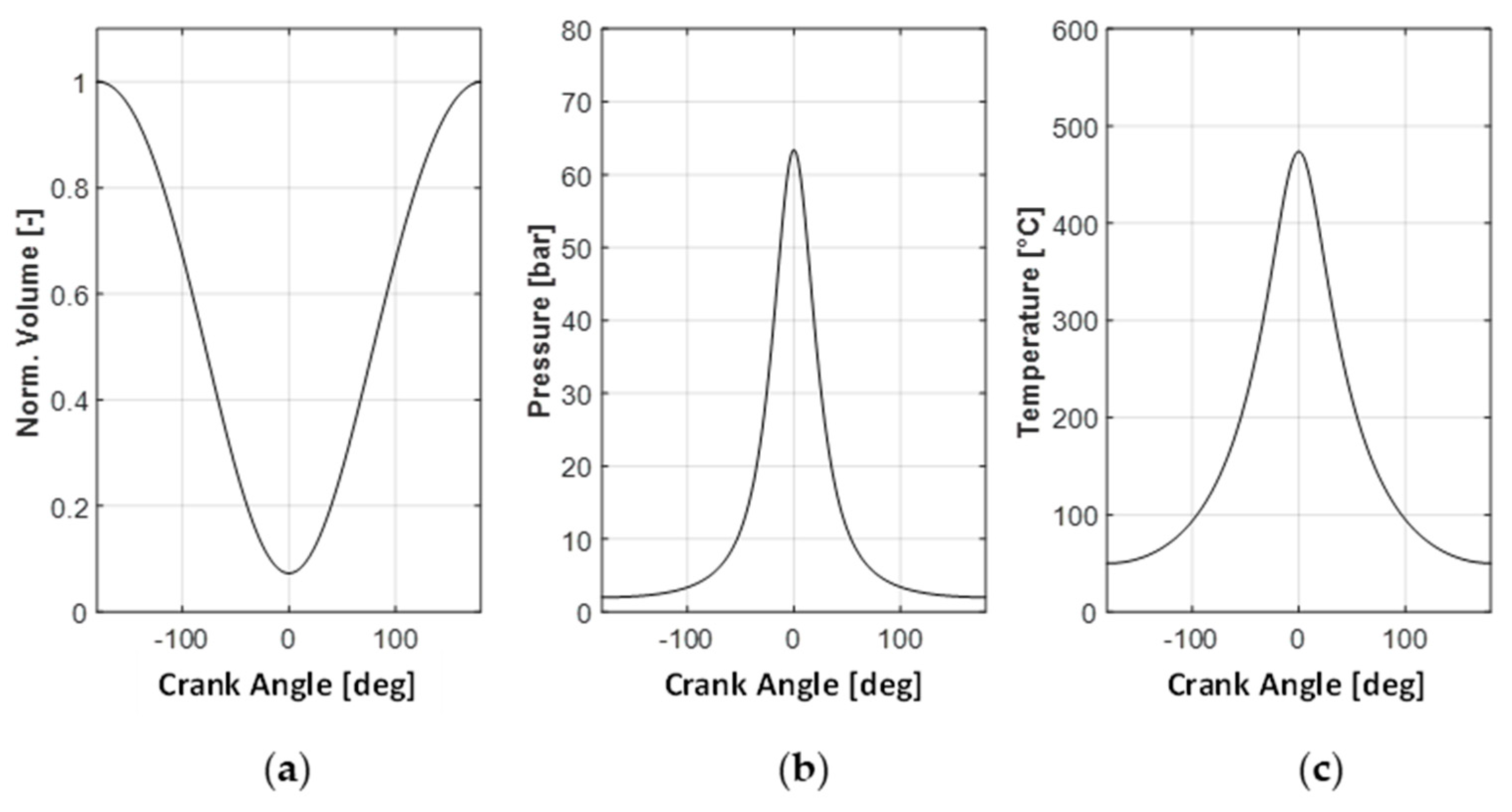
  • Calculation of the pressure and temperature in correspondence with the spark angle through Equations (5) and (6) (once the pressure and temperature in the intake manifold have been measured);
  • Interpolation of the base ignition delay map (Figure 3) characterized at the reference lambda value;
  • Estimated ignition delay correction based on lambda deviation with respect to the reference value (the base ignition delay is multiplied by K τ , i.e., the output of the map reported in Figure 4).
The procedure discussed above can be used to obtain a robust real-time estimation of the ignition delay ( τ e ). Figure 5 shows, as an example, the result obtained during one acceleration performed with the 2017 engine in the Monza circuit (Cylinder 1, out of Turn 2).
The results reported in Figure 5 demonstrate that the presented approach is suitable for performing accurate real-time estimation of the ignition delay. Once the ignition delay model was set up, the estimated model could be used for the diagnosis of pre-ignition events.

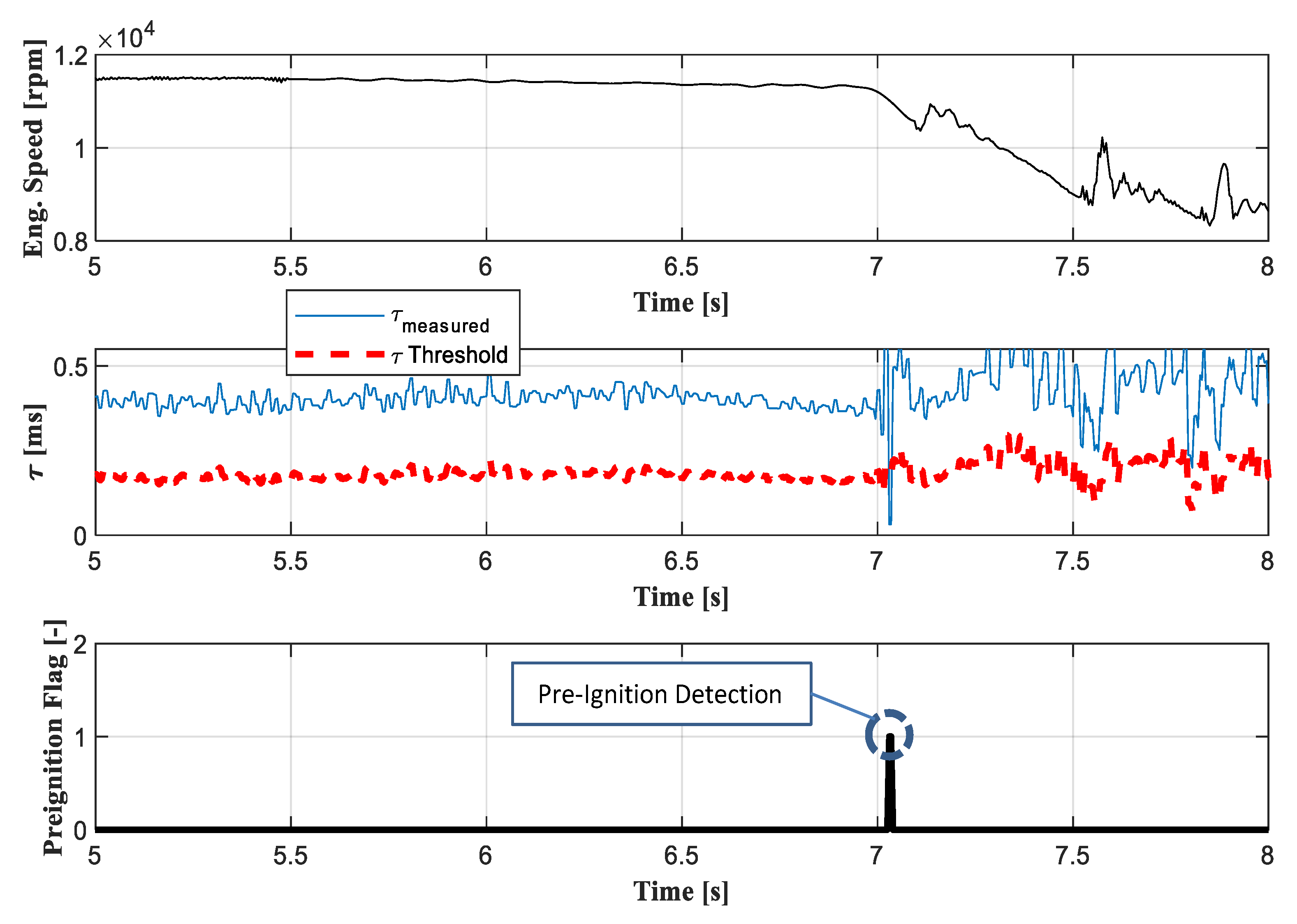
2.3. Pre-Ignition Detection

The discussed ignition delay model provides accurate real-time estimation of that quantity in all operating conditions. Therefore, the output of the model can be compared in real time with the ignition delay calculated from the combustion indices through Equation (2).
In this approach, the strategy for real-time pre-ignition diagnostics compares the measured ignition delay with a calibrated percentage of the modelled delay: when τ m becomes smaller than the calibrated threshold (proportional to τ e ), a pre-igniting cycle is diagnosed. As a matter of fact, pre-igniting cycles are characterized by extremely short (or negative) ignition delays not compatible with the time necessary to activate the combustion process using the spark plug.
To clarify how the detection algorithm works, Figure 6 reports an example in which one abnormal combustion is detected when the measured τ m becomes smaller than 50% of the estimated τ e .
As can be observed, the algorithm for pre-ignition detection captures the occurrence of the abnormal combustion by performing a real-time plausibility check of the ignition delay. In the reported case, the abnormal combustion was due to the degradation of a spark plug, which produced a hot spot in the combustion chamber. Further investigations clarified that the presented algorithm detected the occurrence of a problem related to the spark malfunctioning, which would have probably led to runaway pre-ignition and engine failure.
In the case shown in Figure 6, acquired while the engine was running in a test cell, no failure occurred because the engine was immediately stopped. However, since unexpected pre-ignitions might occur while the engine is installed in the vehicle and managed by the driver, failures can be avoided only by implementing a proper strategy that, based on the information provided by the detection algorithm, modifies the standard control strategy to mitigate the occurrence of pre-ignition events.

3. Recovery Strategy for Real-Time Engine Protection

Once the whole strategy for real-time detection of pre-igniting cycles was set up, the second step of the work consisted of the development of an automatic recovery strategy for engine protection. When the occurrence of pre-ignition events is detected, the goal of such recovery is (when possible) to mitigate the probability of runaway pre-ignitions, which usually cause catastrophic engine failure.
Even though it is not always possible to avoid failures, especially those due to mechanical problems, the presented strategy aims at keeping under control abnormal combustion which is dangerous for engine reliability over time. This is extremely important in motorsport applications because it allows running the engine in safe conditions (stopping the engine during a race would not be acceptable) with slight performance degradation (automatically applied by the controller).
To set up a proper recovery, it is first necessary to identify the main control parameters that allow us to reduce the pre-ignition probability. As many works have demonstrated [22], in the case of pre-ignition events, the best way to avoid runaway occurrences is to rapidly reduce the engine load. This is usually effective when the auto-ignition is due to a hot spot, because load reduction also reduces the amount of heat transferred to the cylinder walls.
The main drawback related to load reduction is obviously the simultaneous reduction of engine power, which is the key performance parameter in motorsport applications. To minimize engine performance degradation, in the case of pre-ignition events, the presented strategy reduces the load only in the cylinders where the abnormal combustion actually took place, while the other cylinders keep running in nominal conditions. It is important to highlight that, due to the engine architecture, load reduction in a single cylinder is not feasible at constant λ because the amount of fresh air cannot be controlled cylinder by cylinder (no variable valve actuation system available). As a result, the only way to reduce the load of a single cylinder is to perform a temporary fuel reduction and accept running the cylinder at a leaner lambda (with respect to the optimal value). In this scenario, the most critical aspect to be managed is that SI combustion can be kept stable only in a certain λ range; therefore, the fuel reduction to be applied to limit pre-ignition occurrence will be limited by the maximum acceptable air-to-fuel ratio. With regard to the engine under study, an 8% increase in the air-to-fuel ratio is the maximum acceptable deviation with respect to the reference λ to avoid misfires.
To avoid runaway pre-ignition, the controller monitors a buffer of 50 cycles (one buffer per cylinder), and puts into practice a different recovery strategy according to the number of pre-ignitions diagnosed in that buffer:
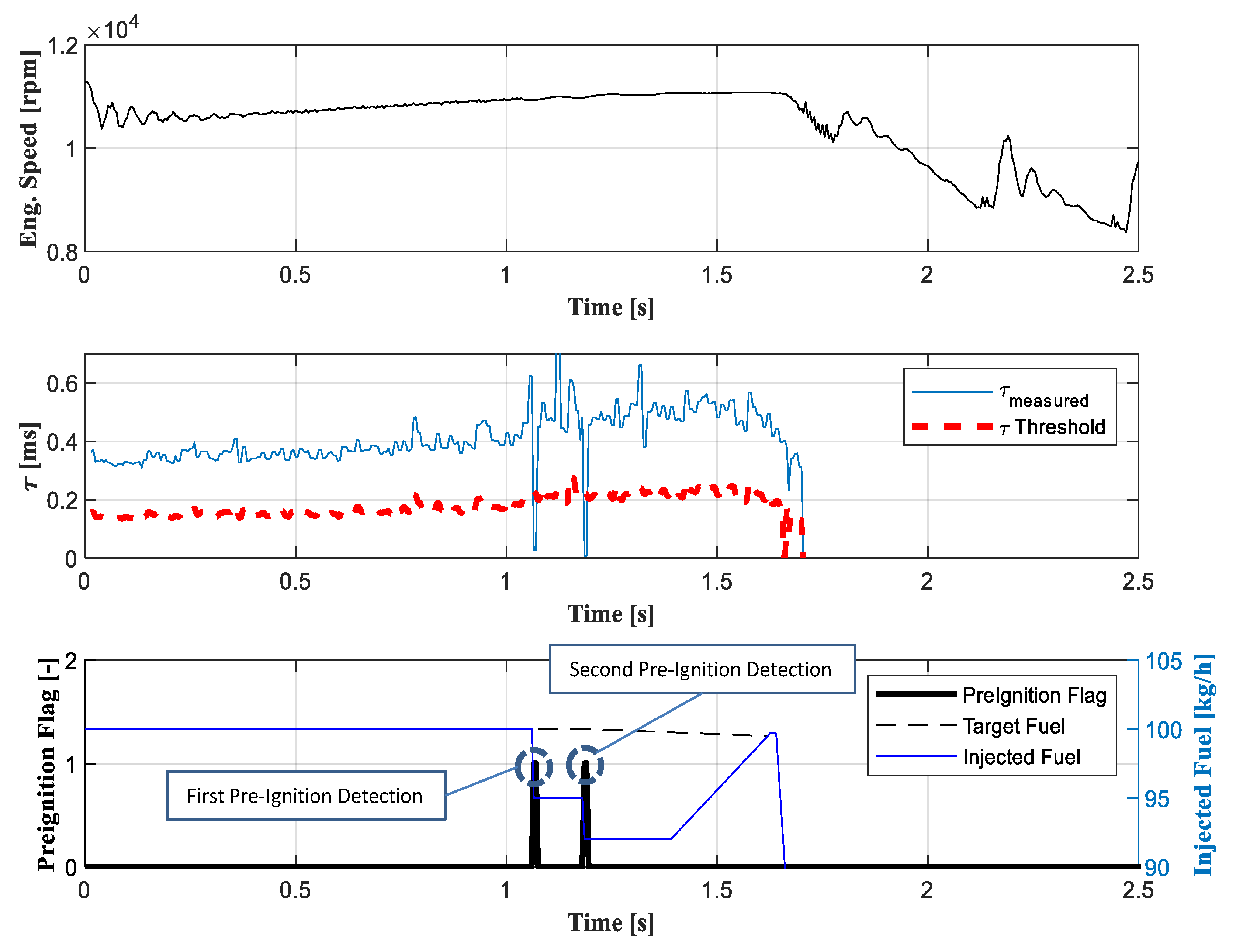
  • First level of recovery: If one pre-ignition event is diagnosed in one cylinder, a 5% fuel reduction is applied to the fuel injected into that cylinder (reduction applied for a tunable number of cycles);
  • Second level of recovery: When one pre-ignition event is diagnosed and another event has already been diagnosed in the last 50 cycles, a further fuel reduction is applied (maximum fuel reduction limited to 8% to avoid lean misfires). The fuel reduction is kept active for a tunable number of cycles;
  • Third level of recovery: When a third pre-ignition event has been detected in the last 50 cycles operated by one cylinder, injection is cut (in that cylinder) for a tunable number of cycles, the goal being to cool the combustion chamber and reduce the temperature of the hot spots.
To clarify the above considerations, Figure 7 reports an example of recovery due to pre-ignition events. In this case, the implemented control strategy applies the first two levels of recovery. As can be observed, when the algorithm detects the first pre-ignition event, a 5% reduction in injected fuel is applied to that cylinder. Then, the occurrence of another pre-ignition event after 14 cycles (and therefore in the same monitored 50 cycle buffer) triggers a further 3% fuel reduction (i.e., an overall 8% reduction with respect to the nominal fuel target).
The developed strategy proved to be effective in diagnosing pre-ignition events and limiting the occurrence of runaway abnormal combustion, i.e., guaranteeing engine reliability with a limited reduction of engine performance.
This strategy, developed over the past years, has been implemented in the engine control units of the Ferrari engines used for Formula 1 applications (provided to Ferrari and customers) and is currently used in both dyno and track applications.

4. Conclusions

In recent years, the concepts of downsizing and boosting have been intensively investigated to maximize power and efficiency in modern SI engines for either standard or motorsport applications. Unfortunately, supercharged engines might suffer from abnormal combustion processes, especially knock (end-gas auto-ignition) and pre-ignition (uncontrolled ignition due to hot spots inside the combustion chamber), which potentially lead to uncontrolled combustion processes. Both abnormal combustions are characterized by impulsive energy releases and high pressure peaks, which might lead to engine degradation and failure.
This work focused on the pre-ignition investigation which was carried out on the Ferrari engines used in Formula 1. In this application, the engines are equipped with one pressure sensor per cylinder (all processed by an on-board indicated system); therefore, both ignition and injection can be adjusted based on the combustion indices calculated in real time from the in-cylinder pressure traces. In this scenario, we developed a model-based control strategy which detects pre-igniting combustion by comparing the measured ignition delay (calculated through the analysis of the in-cylinder pressure trace) with the output of an ignition delay model (identified through specific experimental tests and stored in the ECU).
Once the occurrence of pre-igniting cycles has been diagnosed, the strategy triggers an automatic recovery process for engine protection, the goal being to mitigate the probability of runaway pre-ignitions. Based on the number of pre-ignition events diagnosed in a calibrated buffer of cycles, the strategy performs a proper reduction of the injected fuel (such a reduction is applied only to the cylinder in which the pre-ignitions occurred). The obtained results demonstrate that the developed approach is suitable for diagnosing pre-ignition events and limiting the occurrence of runaway abnormal combustion.
The developed strategy for the diagnosis and control of pre-ignition events is currently implemented in the engine control units of all the Ferrari engines used in Formula 1. However, the presented approach is methodological and could also be applied to standard spark-ignited engines (with different architectures) used in common automotive applications.

Author Contributions

Conceptualization, V.R.; methodology, V.R.; software, V.R.; validation, V.R.; formal analysis, V.R. and C.B.; investigation, V.R.; resources, C.B.; data curation, V.R.; writing—original draft preparation, V.R. and C.B.; writing—review and editing, V.R. and C.B.; visualization, V.R.; supervision, C.B.; project administration, C.B.

Funding

This research received no external funding.

Conflicts of Interest

The authors declare no conflict of interest.

Nomenclature

MFBMass fraction burned
RoHRRate of heat release
pIn-cylinder pressure
pBoostBoost pressure
TIn-cylinder temperature
TBoostBoost temperature
VIn-cylinder volume
θ Crankshaft angle
τ Ignition delay
τ e Estimated ignition delay
τ m Measured ignition delay
MFB 10 Angular position at which 10% of fuel burned within the cycle is reached
SASpark advance
BDCBottom dead center
TDCTop dead center
BTDCBefore the top dead center
ATDCAfter the top dead center
γ Specific heat ratio
c p Specific heat at constant pressure
c v Specific heat at constant volume
λ Air–fuel ratio
λ r e f Reference air–fuel ratio
nEngineEngine rotational speed
ECUElectronic control unit
CANController area network

References

  1. FIA. 2009 Formula One Technical Regulations; FIA: Geneva, Switzerland, 2009. [Google Scholar]
  2. FIA. 2014 Formula One Technical Regulations; FIA: Geneva, Switzerland, 2011. [Google Scholar]
  3. Chapman, E.; Costanzo, V. A Literature Review of Abnormal Ignition by Fuel and Lubricant Derivatives. SAE Int. J. Engines 2016, 9, 107–142. [Google Scholar] [CrossRef]
  4. Amann, M.; Alger, T.; Westmoreland, B.; Rothmaier, A. The Effects of Piston Crevices and Injection Strategy on Low-Speed Pre-Ignition in Boosted SI Engines. SAE Int. J. Engines 2012, 5, 1216–1228. [Google Scholar] [CrossRef]
  5. Moriyoshi, Y.; Kuboyama, T.; Morikawa, K.; Yamada, T.; Imai, Y.; Hatamura, K.; Suzuki, M. A Study of Low Speed Preignition Mechanism in Highly Boosted SI Gasoline Engines. SAE Int. J. Engines 2016, 9, 98–106. [Google Scholar] [CrossRef]
  6. Dahnz, C.; Han, K.; Spicher, U.; Magar, M.; Schießl, R.; Maas, U. Investigations on Pre-Ignition in Highly Supercharged SI Engines. SAE Int. J. Engines 2010, 3, 214–224. [Google Scholar] [CrossRef]
  7. Amann, M.; Alger, T.; Mehta, D. The Effect of EGR on Low-Speed Pre-Ignition in Boosted SI Engines. SAE Int. J. Engines 2011, 4, 235–245. [Google Scholar] [CrossRef]
  8. Tamura, K.; Utaka, T.; Kamano, H.; Hayakawa, N.; Miyasaka, T.; Ishino, T.; Iijima, A.; Shoji, H. Abnormal Combustion Induced by Combustion Chamber Deposits Derived from Engine Oil Additives in a Spark-Ignited Engine. SAE Int. J. Engines 2015, 8, 200–205. [Google Scholar] [CrossRef]
  9. Amann, M.; Mehta, D.; Alger, T. Engine Operating Condition and Gasoline Fuel Composition Effects on Low-Speed Pre-Ignition in High-Performance Spark Ignited Gasoline Engines. SAE Int. J. Engines 2011, 4, 274–285. [Google Scholar] [CrossRef]
  10. Mubarak Ali, M.; Hernandez Perez, F.; Vedharaj, S.; Vallinayagam, R.; Dibble, R.W.; Im, H.G. Effect of Timing and Location of Hotspot on Super Knock during Pre-ignition. SAE Tech. Pap. Ser. 2017. [Google Scholar] [CrossRef]
  11. Moriyoshi, Y.; Yamada, T.; Tsunoda, D.; Xie, M.; Kuboyama, T.; Morikawa, K. Numerical Simulation to Understand the Cause and Sequence of LSPI Phenomena and Suggestion of CaO Mechanism in Highly Boosted SI Combustion in Low Speed Range. SAE Tech. Pap. 2015. [Google Scholar] [CrossRef]
  12. Checkel, M.; Dale, J. Computerized Knock Detection from Engine Pressure Records. SAE Tech. Pap. 1986. [Google Scholar] [CrossRef]
  13. Chun, K.; Kim, K. Measurement and Analysis of Knock in a SI Engine Using the Cylinder Pressure and Block Vibration Signals. SAE Tech. Pap. 1994. [Google Scholar] [CrossRef]
  14. Cavina, N.; Moro, D.; Poggio, L.; Zecchetti, D.; Nanni, R.; Gelmetti, A. Individual Cylinder Combustion Control Based on Real-Time Processing of Ion Current Signals. SAE Tech. Pap. 2007. [Google Scholar] [CrossRef]
  15. Lee, J.; Hwang, S.; Lim, J.; Jeon, D.; Cho, Y. A New Knock-Detection Method using Cylinder Pressure, Block Vibration and Sound Pressure Signals from a SI Engine. SAE Tech. Pap. 1998. [Google Scholar] [CrossRef]
  16. Bejger, A.; Chybowski, L.; Gawdzińska, K. Utilising elastic waves of acoustic emission to assess the condition of spray nozzles in a marine diesel engine. J. Mar. Eng. Technol. 2018, 17, 153–159. [Google Scholar] [CrossRef]
  17. Pipitone, E.; D’Acquisto, L. Development of a low-cost piezo film-based knock sensor. Proc. Inst. Mech. Eng. Part D J. Automob. Eng. 2003, 217, 691–699. [Google Scholar] [CrossRef]
  18. Corti, E.; Forte, C.; Bianchi, G.; Zoffoli, L. A Control-Oriented Knock Intensity Estimator. SAE Int. J. Engines 2017, 10, 2219–2229. [Google Scholar] [CrossRef]
  19. Corti, E.; Forte, C. Combination of In-Cylinder Pressure Signal Analysis and CFD Simulation for Knock Detection Purposes. SAE Int. J. Engines 2010, 2, 268–380. [Google Scholar] [CrossRef]
  20. Heywood, J.B. Internal Combustion Engine Fundamentals; McGraw-Hill: New York, NY, USA, 1988. [Google Scholar]
  21. Singh, E.; Mubarak Ali, M.J.; Ichim, A.; Morganti, K.; Dibble, R. Effect of Mixture Formation and Injection Strategies on Stochastic Pre-Ignition. SAE Tech. Pap. 2018. [Google Scholar] [CrossRef]
  22. Merola, S.; Tornatore, C.; Valentino, G.; Marchitto, L.; Corcione, F. Optical Investigation of the Effect on the Combustion Process of Butanol-Gasoline Blend in a PFI SI Boosted Engine. SAE Int. J. Engines 2011, 2, 632–644. [Google Scholar] [CrossRef]
Figure 1. The in-cylinder pressure (a), rate of heat released (b), and mass fraction burned (MFB) shape (c) for an engine cycle run in partial load conditions, together with the calculated MFB10.
Energies 12 02277 g001
Figure 2. The in-cylinder volume normalized with respect to its maximum (a), estimated motored pressure (b), and estimated motored temperature (c) for a cycle run at full load.
Energies 12 02277 g002
Figure 3. Ignition delay at the reference lambda, mapped as a function of the estimated in-cylinder pressure (P) and temperature (T) in correspondence with the spark advance (SA).
Energies 12 02277 g003
Figure 4. Ignition delay correction based on the difference between the actual and reference lambda.
Energies 12 02277 g004
Figure 5. Telemetry data acquired during the second practice run of the 2017 Monza GP, measured vs. modelled ignition delay.
Energies 12 02277 g005
Figure 6. Telemetry data acquired during a long run operated in a test cell running the 2017 engine. The threshold for pre-ignition detection here equals 50% of the modelled ignition delay.
Energies 12 02277 g006
Figure 7. Telemetry data acquired during a long run operated in a test cell running the 2017 engine. The threshold for pre-ignition detection equals 50% of the modelled ignition delay. The first and the second detected pre-ignition events trigger 5% and 8% reductions, respectively, of the injected fuel with respect to the target injected fuel.
Energies 12 02277 g007

