Abstract
This paper presents the algorithms, hardware overview and testing results for controlling discharge currents from mixed battery modules placed in a parallel configuration. Battery modules with different open-circuit voltage (OCV), internal impedance or even state of charge (SOC) between modules are usually used to form a battery pack. Parallel placed mixed battery modules are typically seen in second-life, repurposed or exchangeable battery systems to increase power and energy storage capacity of a battery pack in mobile, electric vehicle (EV) and stationary energy storage application. This paper addresses battery module heterogeneity by taking advantage of buck regulators on each battery module and formulating scheduling algorithms to dispatch the buck regulators to balance the current out of each battery module. In this way, mixed battery modules can be combined and coordinated to provide a balanced power flow and guarantee safety of the total battery pack. Both open-loop and closed-loop scheduling of buck regulated battery modules are analyzed in this paper. In the open-loop algorithm, buck regulator dispatch commands are computed based on full knowledge of the OCV and impedance of each battery module, while monitoring the load impedance. In the closed-loop algorithm, dispatch commands are generated automatically by a digital proportional-integral-derivative (PID) feedback controller for which battery module current reference signals are computed recursively while monitoring the load impedance. The closed-loop scheduling method is also validated through experimental work that simulates a battery pack with several parallel placed buck regulated battery modules. The experimental results illustrate that the current from each battery module can be rated based on the SOC of each module and that the current remains balanced, despite discrepancies between OCV and internal impedance between modules. The experimental results show that the closed-loop algorithm allows scheduling of buck regulated battery modules, even in the absence of knowledge on the variations of OCV and impedance between battery modules.
1. Introduction
Increased investments in renewable energy technologies hope to reduce environmental pollution, improve energy security and provide economic benefits [1]. Volatility and irregularity of renewable energy production necessitates distributed battery energy storage systems (BESS) to regularize power flow and make renewable energy sources economically viable solutions for grid support [2,3]. Furthermore, batteries of a BESS are actually crucial for the operation of an electric vehicle (EV) and the electrification of transport is one path to reduce CO emissions [4]. As such, BESS with high capacity are needed in both EV applications and renewable energy grid support functions [5,6].
Typically, a battery pack of a BESS is built up from multiple battery cells where series connections are used to provide the BESS terminal voltage and both series and parallel connections are used to increase storage capacity and maximum power output of the BESS. Most BESS use lithium-ion battery (LIBs) cells to provide high voltage with a desired energy capacity, long life span, low self-discharge rate and fast charging capabilities [7,8]. For example, a LIB-based BESS is considered as the primary energy source for most EVs to provide a compromise between driving range and battery size [9,10]. Furthermore, a LIB-based BESS can also be based on a second-life battery system recycled from EVs to provide grid supporting functions, such as demand charge management, renewable energy integration and regulation energy management [11,12]. Especially in second life battery systems recycled from EVs, the parallel placed batteries may have different capacity, different state of health (SOH) and/or different electrical characteristics such as open-circuit voltage (OCV) or internal impedance. It is clear that two parallel placed batteries with a difference in OCV due to a state of charge (SOC) or SOH will result in excessive start currents between the batteries. Furthermore, even if parallel placed batteries do have the same OCV, a difference in internal impedance when batteries are under load will cause a shift in the terminal voltage and again result in unbalanced currents between the batteries. This will cause certain batteries to deplete faster than others. It is therefore important to control the voltage of the batteries in lieu of the uncertainty with respect to the OCV and the internal impedance of the parallel placed batteries.
For the discussion and analysis presented in this paper, we consider a battery pack depicted schematically in Figure 1 where each battery module is considered to be formed by connecting a fixed number of (LIB-based) cells placed in series to satisfy a desired OCV of the individual battery module [13]. In addition, each battery module will be equipped with a current sensor and a buck regulator to allow for modulation of the terminal voltage of the battery module. The buck regulator serves as a DC-to-DC power converter controlled by pulse-width modulation (PWM) to (multiple) metal-oxide-semiconductor field-effect transistors (MOSFETs) to efficiently step down terminal voltage of a battery module [14]. Finally, a full battery pack is formed by connecting multiple battery modules in parallel to a common DC-bus to increase the storage capacity and power rating of the full battery pack as a whole, as indicated in Figure 1. The common DC-bus may be used to serve a unknown load such as an DC/AC inverter for grid supporting functions or an AC motor in an EV application.
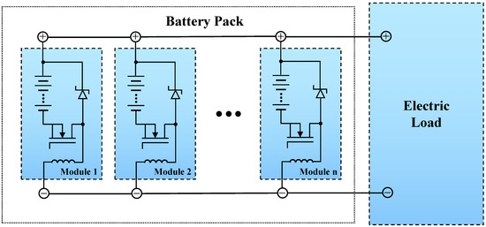
Figure 1.
System diagram of parallel buck regulated battery modules. In each module, the battery is represented by a series connection of battery cells to create the desired OCV, while a BMS with MOSFET microcontroller controlled switch with a flyback diode and inductor are used for regulation of the battery voltage on the parallel bus.
Next to the full battery pack, a LIB based battery management system (BMS) can be used to monitor the OCV, internal impedance and SOC for each module independently to ensure a safe operation region [15,16]. The design of a BMS is beyond the scope of this paper, but we consider measurements of a BMS to help in the scheduling of the buck regulated battery modules. For example, the SOC of each module can be used to balance the desired current from each module [17,18]. This ensures all modules are discharged proportionally [19] to maximize the battery pack life cycle, especially when the battery pack ages and the number of total charge/discharge cycles increases [20].
In the case of parallel placed battery modules, it is clear that BMS information on battery parameters such as OCV and internal impedance is needed for the (open-loop) dispatch of the PWM to the buck regulators to avoid stay currents and guarantee balanced currents out of the modules. Unfortunately, variability in such battery parameters are inevitable due to production and possible mixing of (aged) battery modules [21,22] further exacerbating the discrepancies between modules. The discrepancy between battery modules also limits the ability to extract or store the full electrical energy capacity in the battery pack [23,24]. This motivates the development of a BMS with the capability to control and schedule the PWM to the buck-regulators in the battery modules to allow for a robust high power battery pack. The battery is modeled as a SOC and SOH dependent voltage source and internal impedance. Such a simplified model suffices for modeling the main contributions of the terminal voltage of the battery. This model is therefore used for the regulation of the modulated voltage of the battery via a buck regulator to adjust the voltage of the regulated battery.
In light of heterogeneous battery modules, it is necessary to develop a control and scheduling algorithm to mitigate the impact of the possible differences between battery modules. One approach would be to operate batteries with lower internal resistances over a wider SOC range, which allows battery pack lifespan to be defined by the average battery capacity instead of the worst battery capacity [24]. An alternative approach is to assign lower SOC to smaller battery capacity, which can significantly improve capacity homogeneity and eventually extend battery pack lifespan [25]. Furthermore, a multiple objective (homogenize internal resistances and fault detection) optimization with multi-level converters (MLCs) is regarded as a suitable control approach for balancing both charge and temperature within battery packs [26,27]. Although these algorithms are able to deal with difference in SOC and battery parameters between modules, they tend to be computationally complex and require reliable high speed communication between battery modules to provide optimal scheduling.
The scheduling of multiple battery modules in a heterogeneous battery pack is solved in this paper by finding the optimal terminal voltage of each individual module via either an open-loop or closed-loop control algorithm. Using a previously developed open-loop centralized algorithm [28] as a basis, a scheduling algorithm with a decentralized closed-loop architecture is developed to dispatch the PWM for each buck regulator. The decentralized architecture ensures that no high-speed communication is required between battery modules.
In the decentralized closed-loop architecture, PWM dispatch is generated by a standard digital proportional-integral-derivative (PID) feedback controller, but for which battery module current reference signals are computed recursively while monitoring the load impedance. The proposed recursive scheduling ensures that at least one of the battery modules will operate at a full or close to 100% PWM, without the explicit knowledge of the electrical module parameters such as OCV or internal impedance and despite a time-varying load connected to the battery pack. The closed-loop scheduling method is also validated through experimental work that simulates a battery pack with several parallel placed buck regulated battery modules. The experimental results illustrate that the current from each battery module can be rated based on the SOC of each module and that the current remains balanced, despite discrepancies between OCV and internal impedance between modules.
The remainder of the paper is outlined as follows. In Section 2, the concept and hardware of the parallel buck regulated battery modules are explained, followed by the formulation of module voltages and currents in matrix form. The steps to obtain the open-loop optimal current scheduling and development of both centralized and decentralized scheduling algorithms are outlined in Section 3. The recursive scheduling algorithm with closed-loop control is explained in Section 4, and the validity of the algorithms via experimental work is outlined in Section 5. The paper ends with a summary of proposed current scheduling algorithm’s development process and effectiveness in Section 6.
2. Parallel Buck Regulated Battery Modules
2.1. Module Formulation and Assumptions
Current scheduling of parallel placed battery modules is executed by buck regulators, which are composed of a PWM-driven MOSFET, a flyback diode and an inductor, as shown in Figure 1. It is worth noting that a properly chosen MOSFET with low drain-to-source on-resistance is suitable for high current switching and as a buck regulator hardly decrease the efficiency of the battery system. Technically, a buck regulator acts as a solid-state, Pulse Width Modulated (PWM) switch with little to no energy loss. A battery pack is formed by a set of any number of parallel-connected battery modules with buck regulated and series-connected battery cells and ultimately connect the unit to the electric load. It should be noted that module number n is arbitrary, because a battery pack can be fully or partially arranged with battery modules to deliver the desired voltage, capacity, or power density to significantly enhance the flexibility of the battery systems.
For the derivation of the current optimal scheduling algorithm, the battery system of parallel placed buck regulated battery modules is approximated as a group of adjustable power supplies in parallel, as shown in Figure 2. Specifically, we assume that each battery module k with a serial of multiple cells is characterized by a modulated ideal voltage supply with a terminal voltage in series with an internal impedance . For each battery module k, we presume the following knowledge:
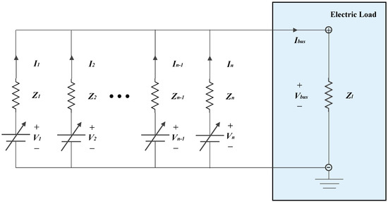
Figure 2.
Model for current scheduling.
- The ideal voltage supply can be given by , where the Open Circuit Voltage (OCV) is the terminal voltage of a battery module in the case no external load is connected. The voltage modulation coefficient represents the PWM duty cycle of MOSFET applied by a buck regulator.
- The slowly time-varying internal impedance of a battery module is given by a constant and possibly known value in comparison with the time-varying natural of the external unknown load impedance .
Applying Kirchhoff’s circuit laws now yields the following relationships for the above-mentioned battery system shown in Figure 2:
- The algebraic sum of current of each battery module is equal to bus currentdue to Kirchhoff’s current law (KCL).
- Similar to KCL, the bus voltage can be satisfiedfor each battery module k due to Kirchhoff’s voltage law (KVL).
2.2. The Formulation of Module Voltages and Module Currents
The above fundamental equalities (Equations (1) and (2)) of the battery system can be combined to compute bus current and bus voltage when a load with impedance value is applied to connect battery back with parallel placed battery modules. With the knowledge of a given set of values for modulated voltages , individual module current can be determined by
Recalling that the bus current can be derived from individual module current from the relationship in Equation (1), we can solve bus voltage via
This allows us to recreate
which is equivalent to
From last expression, the bus voltage can be computed by the linear combination
where the “gain factors” are given by a combination of impedances from the parallel placed battery modules and the load .
2.3. Impedance Matrix and Current Vector
With the individual module currents given in Equation (3) and bus voltage given in Equation (4), we can then obtain as a typical linear combination of all modulated module voltages :
where the summation index has been changed to m to avoid confusion with the specific module current indexed with k. The above expression for can be simplified as an insightful linear combination expression
The coefficients and can build up a impedance matrix , which relates module currents to module voltage given by
The impedance matrix is very useful for the explicit computation of module currents as a function of the module voltages and vice versa. It can be easily observed from the definition of the impedance matrix that, with all impedance values being positive, D is also positive definite and symmetric, making D nonsingular. With D invertible, module voltages can be computed as a function of desired module currents for the parallel placed battery modules.
3. Open-Loop Optimal Current Scheduling
3.1. Relative Scaling of Module Currents
Given the knowledge of impedance matrix with the internal module impedance and a fixed (but unknown) load impedance , an optimal current scheduling problem can be formulated that balanced the module currents . Balanced module currents are obtained by computation of buck regulated module voltages , such that module currents can be balanced to satisfy
where the coefficients is used for absolute scaling and specifies the relative scaling of the module current . It should be noted that the value represents for battery module discharging, whereas for battery charging. The relative scaling of the module currents I is based on the individual state of charge of each battery module and defined as
and
where of module k is satisfied by ; .
The above expression for guarantees that battery modules with smaller SOC will charge faster with larger current compared to battery modules with a larger SOC. Battery modules with a smaller SOC will discharge less current compared to battery modules with a larger SOC. In the case where all modules have the same storage capacity and the same SOC, and can be required to follow the same charging/discharging profile, the relative scaling of the module currents I given by Equation (7) can be satisfied to be identical . This makes
and is denoted by equal SOC current based scheduling throughout this paper.
3.2. Module Current Scheduling via Linear Programming
Given the full information of the invertible impedance matrix D with each internal impedance and external load impedance in Equation (6), we can explicitly compute the set of optimal modulated module voltages from a desired set of module currents . Using vector notation
for module voltages, vector format I in Equation (7) for module currents, and invertible impedance matrix D in Equation (6), the optimal current scheduling can be written as a typical linear programming (LP) problem that requires to compute the maximum value of the current absolute scaling (for discharging) such that . By rewriting that
from Equation (6) and the optimization for absolute scaling of module currents can be expressed in standard form as
which is equivalent to a LP problem for numerical computation (MATLAB)
The LP formulation in Equation (9) provides the numerical tool to compute the optimal solution that can maximize module current I by finding the maximum value , given the constraints on for each module. Once the optimal absolute scaling is obtained, both optimal module currents and voltages can be explicitly computed via
and
3.3. Decentralized Recursive Optimal Current Scheduling
Although the LP problem of centralized current scheduling in our previous work [28] can be computed with fast computing hardware, measurements and communication of a large bus voltage and a high bus current may require dedicated hardware and optical isolation devices. Furthermore, when the number n of modules becomes large, the communication to update of puts additional requirements on the speed and reliability of the communication hardware, and the ability to respond to the information request in a timely manner gets reduced.
Instead of centralized communication, we propose a solution that replaces the measurements of and and reduces the centralized communication requirements by a decentralized recursive module current scheduling. To explain the decentralized recursive module current scheduling, first it should be noted that the measurement of and can be replaced by the measurement of a single module current performed by any module m. From the KVL in Equation (2), the measurement of can be replaced by a measurement of a module current and computed by . Secondly, it can be noted that, once bus voltage is known, all the module currents can now be computed via
allowing to recreate bus current via
With both bus voltage and bus current now obtained from the above expressions, the same load impedance estimate can be obtained via
which allows updating the impedance matrix D the computation of the optimal module voltages via the LP problem of Equation (9).
It can be observed that the measurement of the current of module m and the computation of the bus voltage in Equation (14) can be done decentralized within each module m, without any centralized communication requirements. Furthermore, if each module m holds the knowledge on all the initial module voltages and the internal impedances , the bus current in Equation (13) can be computed and the information on all the optimal module voltages can be solved by the same LP problem of Equation (9) and maintained in each module m. In this way, each module m computes its own optimal voltage and keeps track of the optimal voltages of the other modules, which eliminates the need for high speed central communication of the individual module voltages to each of the modules. The only centralized communication that would have to take place is the update on the possibly slowly changing internal impedances and state of charge of each module . Since both and only changes slowly, such centralized communication can be done at a much smaller update rate.
The ideas on the locally decentralized computation of the bus voltage and the bus current can now be used to solving the LP problem in Equation (9) recursively in time and summarized in the following procedure:
Decentralized current scheduling procedure:
- Assume fixed internal impedances but a time-varying load impedance .
- Set initial time index and communicate the n elements of the initial module voltages to each of the corresponding modules .
- At time index t, each individual module m measures the module current and compute the bus voltagethe bus currentand further update the impedance matrix in Equation (6) with full information of internal impedance and estimated load impedance .
- Before the subsequent time Step , each individual module updates the optimal module voltages according towhere is obtained by the LP problem in Equation (9) solved in each module.
- At time Step , each module m updates the module voltage to of the
- Increment time index and restart from Step 1.
It should be noted that the recursive updates of optimal module voltages explained above is again able to converge in a single time step in the case is fixed at time Step t. Due to the decentralized nature of measuring module current and solving the same LP problem within each individual module, additional communication requirement of measurement and optimal computation of module voltage is not necessary, which can allow a large battery pack of multiple modules n to track time-varying load demands with little communication traffic. For robustness and time drift avoiding, only temporary communication of internal impedance and timing clock for synchronous updates of at time index are required.
3.4. Numerical Illustration of Recursive Equal SOC Current Scheduling
To illustrate the recursive updates of the internal module voltages for equal SOC current scheduling, we consider a numerical example of parallel placed battery modules with full scale module OCVs of
For illustration of the sensitivity of the open-loop scheduling with respect to knowledge of the internal impedance of the battery modules, two different scenarios were considered. The first scenario assumed an unknown time-varying load, but perfect knowledge of the internal impedance. In the second scenario, the internal impedance of the battery modules was assumed to be incorrect.
Before demonstrating the numerical results, it is worthwhile to show the need for current scheduling of battery modules with different internal impedance values. Assuming internal impedance values
and a time-varying load, the current of the individual battery modules when the for each module k is simply fixed to 100% is illustrated in Figure 3. It can be seen that, due to the varying load (bottom of figure), the current produced by each module varied significantly and there may be stray current between modules due to the difference in OCV between the modules.
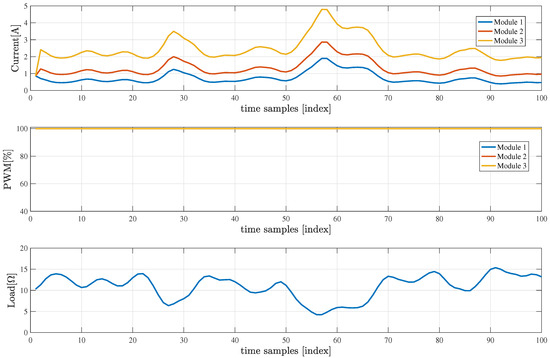
Figure 3.
Currents in battery modules (top) and PWM modulation (all 100%) of battery voltage (middle) without recursive SOC balanced module scheduling of three parallel placed battery modules with accurate estimated internal impedance, subjected to a time-varying external load (bottom).
Unknown, Time-Varying External Load
To illustrate the recursive updates of the internal module voltages for equal SOC current scheduling, we consider the known internal impedance values given in Equation (16) and again subjected to a time-varying external load impedance over a DT index t, as shown in Figure 4 (bottom). To adjust module voltages of
with the PWM modulation factor , and , the decentralized iteration steps outlined above is followed to maintain balanced (equal) module currents. The numerical results for recursive time-varying balanced (equal) current scheduling is summarized in Figure 4, where it can be seen in top figure that the individual module currents stay relatively close, despite the presence of a time-varying external load. This is clearly an improvement over the results in Figure 3 when no current balancing is used under same time-varying load scenario.
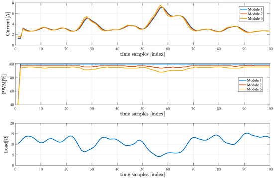
Figure 4.
Currents in battery modules (top) and PWM modulation of battery voltage (middle) for recursive SOC balanced module scheduling of three parallel placed battery modules with accurate estimated internal impedance, subjected to a time-varying external load (bottom).
It should be noted that the balanced module currents are caused by the time-varying updates of the module voltages . The time-varying nature of the modulation factor of the three modules is plotted in Figure 4 (middle) and shows that Module 1 is always set at a full modulation of . This is expected, as Module 1 has the highest internal impedance and the lowest OCV of V compared with other modules, which requires the other modules to be modulated down to ensure currents are balanced.
In practice, the internal impedance of each battery module may be unknown, whereas cable and parasitic resistance values may also influence the module voltage on the main DC-bus. Since the computation precision of the optimal value heavily relies on the impedance matrix D, error in the internal impedance of each battery module will lead to erroneous scheduling results.
4. Closed-Loop Current Scheduling
4.1. Decentralized Digital Control
To be robust to incomplete or erroneous information on the internal impedance of each module, a solution is proposed that uses a standard digital proportional-integral-derivative (PID) feedback controller in each module k. Instead of directly dispatching the modulation factor , each module accept a reference value and the decentralized PID controllers in each module computes the necessary the modulation factor .
The digital PID controller is simply given by the standard expression
where is the measurement and is the reference of the current of the kth battery module. The resulting again denotes the PWM dispatch to the buck regulator of the kth battery module at time instance t. The parameters , and and are all non-negative and denote the coefficients for the proportional, integral, and derivative terms, respectively. The PID control in Equation (18) guarantees tracking of to the steady-state value of the desired reference current without specific knowledge of internal impedance and external load impedance .
As indicated by Equation (18), the PID control takes place using local information of the battery module only. As such, the PID control algorithm of Equation (18) is distributed on each and every buck regulated battery module and typically runs at a sampling rate of 100 Hz. To avoid integrator windup, limiters on the PWM duty cycle are put in place so that the controller output never reaches the modulation limits, as illustrated in Figure 5.

Figure 5.
PID current loop control in buck regulated PWM circuit.
Droop control is an alternative to controlling the power flow out of a AC or DC power system by proportionally modulating voltage based on the difference in power flow [29]. Although that may be sufficient for most AC or DC power generation systems, the high sensitivity of stray currents between two parallel placed batteries due to a mismatch in internal impedance does not make droop control very efficient. As an example, consider two parallel placed batteries with an internal impedance of only 10 m. A difference of only 1 V between the OCV of the two batteries may results in a stray current of m) = 50 A. Although such a sustained current difference may not be relevant for an AC or DC power system, for a battery system, this may results in a rapidly growing difference in SOC between the two batteries.
4.2. Recursive Reference Adjustment for Load-Tracking
Coordination between the battery modules is accomplished via the demand or reference signal sent to the battery modules and will be done at much lower sampling rate. In the case of equal recursive SOC current scheduling discussed above, every individual module current reference should be adjusted to be same value of , mathematically expressed as
However, the actual value of the common current reference is not known and still depends on the load and the battery parameters ( and impedance ) of each battery module.
It is necessary to adapt the common current reference to its maximum value where at least one of the battery modules reaches a dispatch signal equal to or close to . This is accomplished via an autonomous update algorithm for the demand signals that will maximize all values of , but not exceed 100%. The autonomous demand-side update can be achieved by monitoring each PWM duty cycle and measuring module currents of every individual module , as shown in Figure 6 and summarized in the following procedure.
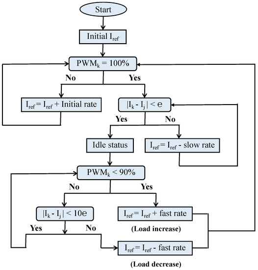
Figure 6.
Flowchart of the autonomous closed-loop control algorithm workflow.
Autonomous closed-loop control procedure:
- Set initial time index and communicate the n elements of the initial reference currents to each of the corresponding modules .
- At time index t, perform a monitor of PWM duty cycle and a measurement of module current of every individual module k. If any module gets to duty cycle, go to Step 3, otherwise update the reference current with a fast ramp-up rate noted by “initial rate” to increase module current .
- If any module gets to (full) duty cycle and the absolute current difference between different modules is less than the current difference threshold e, optimal module currents are found and set to be the same value as the reference current sending the system into an idle status. If not, decrease reference current to with a small ramp-down rate and repeat Step 3 until go to idle status.
- After getting into idle status, if the PWM duty cycle of each module suddenly below the threshold value of , the reference current needs to be increased to with relatively large ramp-up rate and repeat from Step 2, to satisfy larger optimal balanced module currents due to load increase (load impedance decrease) demand. If the PWM duty cycle remains larger than or equal to the threshold of value , go to Step 5.
- In the case the PWM duty cycle of every module becomes larger than or equal to threshold PWM value of but absolute current difference between different modules is larger, it is necessary to decrease reference current to with the same ramp-up rate in Step 4 to find optimal balanced current due to load decrease (load impedance increase) demand. Restart from Step 2.
The proposed algorithm above aims at maximizing the PWM duty cycle of all modules by ensuring that at least one module run at full modulation . Such a modulation to the buck regulators in each battery module ensures that the battery maximizes its power output, while module currents are balanced. It should be noted that this is accomplished without the explicit knowledge of the module , module internal impedance and load impedance . The measurement of the module current and the controller output current can be done within any module at a relative fast update rate without any communication requirements. Any updates on changing reference current would take place at a much slower rate in the central communication back to each module.
There are some additional adjustments that can me made in the case of current measurement inaccuracy. In the case the PWM duty cycle is between (fully off) and (fully on), any limited resolution of current sensor and MOSFET may result in a modulation above 100% to keep the module currents equal. In such scenario, the optimal reference current value to each module needs to be decreased slightly to keep the PWM duty cycle in an reasonable range.
5. Experimental Verification
5.1. Experimental Setup
An experimental setup used for the validation of the proposed optimal current scheduling consisted of three parallel connected buck regulated battery modules, where the modulation demand signal , could be applied and recorded and the current of each battery module can be measured simultaneously. A photograph of the experimental battery tester is shown in Figure 7 with a functional diagram given in Figure 8.
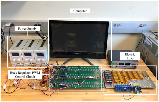
Figure 7.
Photograph of the experimental battery tester.
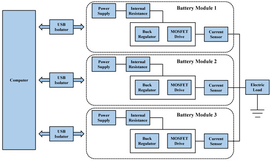
Figure 8.
Schematic of the experimental battery tester.
The parallel connection of three buck regulated battery modules was connected to an electrical load via a common DC bus. The electrical load was programmable and could be varied in both small and large steps covering several . Each parallel connected buck regulated battery module was implemented via an adjustable power supply in series with a variable resistor. Tekpower TP5003T Variable Digital DC Power Supplies were used to simulate a range of OCV for each module, while the variable resistance was used to emulate an arbitrary internal resistance. The buck regulator was composed of a PWM driven MOSFET, a flyback diode and an inductor, and controlled by an Arduino Uno board. The MOSFET’s gate placed on the buck regulator was connected to a digital PWM output pin on the Arduino Uno board and updating an 8 bit PWM at a rate of 62.5 kHz. The Arduino board was also programmed to measure module current real-time signals by 10 bit AD voltage measurements over a small shunt resistor at an accuracy of 27 mA/bit, whereas USB isolators were used to protect the computer equipment from common voltage and ground loop currents. The added cost of the proposed electronics to control stray currents between batteries was minimal. The proposed solutions used serially placed MOSFETs to implement the pulse with modulation at different voltage levels, where an inductor was used to filter voltage ripples. The PWM was controlled using a basic microprocessor embedded in the electronics with either serial or wireless communication between battery modules. In the experimental setup, the additional cost was approximately $25/module.
5.2. Experimental Results with Varying Load Conditions
To verify the applicability of the decentralized closed-loop control algorithms with autonomous load-tracking, the experimental setup was used to emulate three parallel placed battery modules with full scale open-circuit voltages (OCVs) of V, V, V and internal impedance values , , and . Furthermore, cable and module board resistance was not accounted for in the internal impedance, hence the true module impedance values may be different from the assigned impedance values created by the variable resistors. The discrepancy between OCVs and impedances was used to emulate mixed battery modules. The decentralized PID controller of Equation (18) for each module was the same and tuned to have the control parameters , , and and operated at a sampling rate of 100 Hz.
For the experimental results with varying load conditions included in this paper, it was first assumed, based on that each module has the same SOC and capacity storage , to focus on the requirement of equal current scheduling . Two test were performed: both a small step-wise changing external load scenario shown in Figure 9 (bottom) and a large step-wise changing external load scenario shown in Figure 10 (bottom) were used to validate the decentralized closed-loop control algorithms with autonomous load-tracking. It should be pointed out that internal impedance information and the timing and size of the step in the load are unknown to the decentralized closed-loop control algorithms.
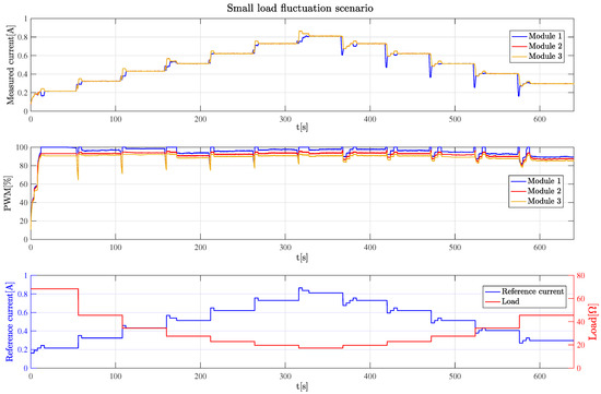
Figure 9.
Currents (top) and modulation of battery voltages (middle) in battery modules for autonomous module current scheduling of three parallel placed battery modules with same battery capacity, reference current and time-varying external load impedance (bottom) under small load fluctuation scenario.
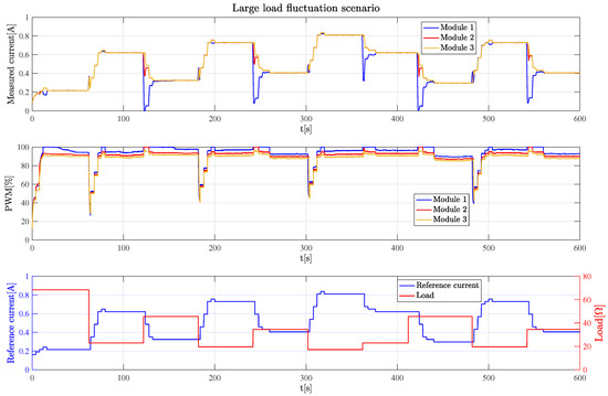
Figure 10.
Currents (top) and modulation of battery voltages (middle) in battery modules for autonomous module current scheduling of three parallel placed battery modules with same battery capacity, reference current and time-varying external load impedance (bottom) under large load fluctuation scenario.
In both scenarios, the requirement of equal current scheduling was used to evaluate and validate the decentralized closed-loop control algorithms with autonomous load-tracking. In Figure 9 (top) and Figure 10 (top), it can be observed that the decentralized control algorithm enables the three module currents to stay relatively closed at steady-state levels equal to each other without any knowledge of internal impedance and variations in the load .
In Figure 9 (middle) and Figure 10 (middle), it can be observed that at least one of modules had a PWM close to 100%, indicating that the autonomous load-tracking maximized the power output of the battery pack. In addition, increasing PWM required certain ramp-up period but decreasing PWM could happen instantaneously to protect the battery modules. The reference current signals were updated every 4 s and recorded, as shown in Figure 9 (bottom) and Figure 10 (bottom), which also include the load variation .
In the third test with varying load conditions included in this paper, it was assumed based on that modules have the same SOC , but have a variation in the capacity storage captured by the relationship . To ensure the SOC of each module progresses simultaneously, the reference current in Equation (19) needed to be altered to .
The small step-wise changing external load scenario shown in Figure 11 (bottom) was used to evaluate the current scheduling using autonomous demand tracking. In Figure 11 (top), it can be observed that the decentralized control algorithm schedules the three module currents proportional to the assumed capacity of the modules. The experiment result shows that currents out of Modules 1 and 2 remained the same and slightly lower (around ) than Module 3 because their capacity degraded to to accommodate their limited capacity of 80% compared to Module 3. In addition, in Figure 11 (middle), it can be seen that Module 1 always stayed at or close to due to its highest impedance and capacity, and lowest OCV.
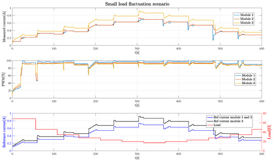
Figure 11.
Currents (top) and modulation of battery voltages (middle) in battery modules for autonomous module current scheduling of three parallel placed battery modules with different battery capacity, reference current and time-varying external load impedance (bottom) under small load fluctuation scenario.
6. Conclusions
Modular battery systems that consist of parallel placed battery modules are essential in range extension of electric vehicles and re-purposing of batteries for integration as energy storage in grid applications. The performance of such modular battery system can be significantly improved if combining or mixing of modules is robust to open-circuit voltage (OCV), state of charge (SOC) and internal impedance of each module.
This paper provides a solution to eliminate module-to-module differences by using buck regulators on each battery module along with distributed closed-loop control with autonomous load-tracking to allow current scheduling of parallel placed battery modules. The distributed closed-loop control is based on standard digital PID control that monitors module current and adjust pulse width modulation (PWM) to the buck regulators to maximize total battery power output. Maximum battery output is accomplished by maximizing the PWM cycle of all modules by ensuring that at least one module runs at full PWM of and module currents are balanced. This is accomplished without the explicit knowledge of the module OCV, module internal impedance and total load impedance.
Experimental results verify the feasibility, effectiveness and accuracy of proposed autonomous demand-side current scheduling of parallel buck regulated battery modules for balancing current out of each individual battery module. Implementation results indicate that balancing individual battery module can be done within each module with fast rate decentralized control, while reference current for real-time load tracking can be updated at slower update rates in order to efficiently reduce the centralized communication requirements. The future work of this study is to apply this proposed autonomous closed-loop control technique into battery management system (BMS) of modular battery systems to improve battery pack performance and extend battery pack lifespan.
Author Contributions
Investigation, Y.J. and L.J.S.; and Writing—review editing, R.A.d.C.
Funding
This research received no external funding.
Conflicts of Interest
The authors declare no conflict of interest.
References
- Ren, H.; Zhao, Y.; Chen, S.; Wang, T. Design and implementation of a battery management system with active charge balance based on the SOC and SOH online estimation. Energy 2019, 166, 908–917. [Google Scholar] [CrossRef]
- Wang, Y.; Shi, W.; Wang, B.; Chu, C.C.; Gadh, R. Optimal operation of stationary and mobile batteries in distribution grids. Appl. Energy 2017, 190, 1289–1301. [Google Scholar] [CrossRef]
- Ghorbanzadeh, M.; Astaneh, M.; Golzar, F. Long-term degradation based analysis for lithium-ion batteries in off-grid wind-battery renewable energy systems. Energy 2019, 166, 1194–1206. [Google Scholar] [CrossRef]
- Wang, Y.; Chen, Z.; Zhang, C. On-line remaining energy prediction: A case study in embedded battery management system. Appl. Energy 2017, 194, 688–695. [Google Scholar] [CrossRef]
- Bouchhima, N.; Schnierle, M.; Schulte, S.; Birke, K.P. Optimal energy management strategy for self-reconfigurable batteries. Energy 2017, 122, 560–569. [Google Scholar] [CrossRef]
- Xia, B.; Shang, Y.; Nguyen, T.; Mi, C. A correlation based fault detection method for short circuits in battery packs. J. Power Sources 2017, 337, 1–10. [Google Scholar] [CrossRef]
- Cai, Y.; Ouyang, M.; Yang, F. Impact of power split configurations on fuel consumption and battery degradation in plug-in hybrid electric city buses. Appl. Energy 2017, 188, 257–269. [Google Scholar] [CrossRef]
- Xia, B.; Zhao, X.; De Callafon, R.; Garnier, H.; Nguyen, T.; Mi, C. Accurate Lithium-ion battery parameter estimation with continuous-time system identification methods. Appl. Energy 2016, 179, 426–436. [Google Scholar] [CrossRef]
- Chen, Z.; Xiong, R.; Tian, J.; Shang, X.; Lu, J. Model-based fault diagnosis approach on external short circuit of lithium-ion battery used in electric vehicles. Appl. Energy 2016, 184, 365–374. [Google Scholar] [CrossRef]
- Liu, Z.; He, H. Sensor fault detection and isolation for a lithium-ion battery pack in electric vehicles using adaptive extended Kalman filter. Appl. Energy 2017, 185, 2033–2044. [Google Scholar] [CrossRef]
- Tong, S.J.; Same, A.; Kootstra, M.A.; Park, J.W. Off-grid photovoltaic vehicle charge using second life lithium batteries: An experimental and numerical investigation. Appl. Energy 2013, 104, 740–750. [Google Scholar] [CrossRef]
- Deng, Y.; Li, J.; Li, T.; Zhang, J.; Yang, F.; Yuan, C. Life cycle assessment of high capacity molybdenum disulfide lithium-ion battery for electric vehicles. Energy 2017, 123, 77–88. [Google Scholar] [CrossRef]
- Finesso, R.; Spessa, E.; Venditti, M. Cost-optimized design of a dual-mode diesel parallel hybrid electric vehicle for several driving missions and market scenarios. Appl. Energy 2016, 177, 366–383. [Google Scholar] [CrossRef]
- Siu, M.; Mok, P.K.; Leung, K.N.; Lam, Y.H.; Ki, W.H. A voltage-mode PWM buck regulator with end-point prediction. IEEE Trans. Circuits Syst. II Express Briefs 2006, 53, 294–298. [Google Scholar]
- Jiang, Y.; Zhao, X.; Valibeygi, A.; de Callafon, R.A. Dynamic prediction of power storage and delivery by data-based fractional differential models of a lithium iron phosphate battery. Energies 2016, 9, 590. [Google Scholar] [CrossRef]
- Sturm, J.; Ennifar, H.; Erhard, S.; Rheinfeld, A.; Kosch, S.; Jossen, A. State estimation of lithium-ion cells using a physicochemical model based extended Kalman filter. Appl. Energy 2018, 223, 103–123. [Google Scholar] [CrossRef]
- Jiang, Y.; Xia, B.; Zhao, X.; Nguyen, T.; Mi, C.; de Callafon, R.A. Identification of Fractional Differential Models for Lithium-ion Polymer Battery Dynamics. IFAC-PapersOnLine 2017, 50, 405–410. [Google Scholar] [CrossRef]
- Jiang, Y.; Xia, B.; Zhao, X.; Nguyen, T.; Mi, C.; de Callafon, R.A. Data-based fractional differential models for non-linear dynamic modeling of a lithium-ion battery. Energy 2017, 135, 171–181. [Google Scholar] [CrossRef]
- Zhao, X.; de Callafon, R.A.; Shrinkle, L. Current Scheduling for Parallel Buck Regulated Battery Modules. IFAC Proc. Vol. 2014, 47, 2112–2117. [Google Scholar] [CrossRef]
- Chiu, K.C.; Lin, C.H.; Yeh, S.F.; Lin, Y.H.; Huang, C.S.; Chen, K.C. Cycle life analysis of series connected lithium-ion batteries with temperature difference. J. Power Sources 2014, 263, 75–84. [Google Scholar] [CrossRef]
- Vetter, J.; Novák, P.; Wagner, M.; Veit, C.; Möller, K.C.; Besenhard, J.; Winter, M.; Wohlfahrt-Mehrens, M.; Vogler, C.; Hammouche, A. Ageing mechanisms in lithium-ion batteries. J. Power Sources 2005, 147, 269–281. [Google Scholar] [CrossRef]
- Diao, W.; Xue, N.; Bhattacharjee, V.; Jiang, J.; Karabasoglu, O.; Pecht, M. Active battery cell equalization based on residual available energy maximization. Appl. Energy 2018, 210, 690–698. [Google Scholar] [CrossRef]
- Altaf, F.; Johannesson, L.; Egardt, B. Simultaneous thermal and state-of-charge balancing of batteries: A review. In Proceedings of the 2014 IEEE Vehicle Power and Propulsion Conference (VPPC), Coimbra, Portugal, 27–30 October 2014; pp. 1–7. [Google Scholar]
- Rehman, M.M.U.; Evzelman, M.; Hathaway, K.; Zane, R.; Plett, G.L.; Smith, K.; Wood, E.; Maksimovic, D. Modular approach for continuous cell-level balancing to improve performance of large battery packs. In Proceedings of the 2014 IEEE Energy Conversion Congress and Exposition (ECCE), Pittsburgh, PA, USA, 14–18 September 2014; pp. 4327–4334. [Google Scholar]
- Rehman, M.M.U.; Zhang, F.; Evzelman, M.; Zane, R.; Smith, K.; Maksimovic, D. Advanced cell-level control for extending electric vehicle battery pack lifetime. In Proceedings of the 2016 IEEE Energy Conversion Congress and Exposition (ECCE), Milwaukee, WI, USA, 18–22 September 2016; pp. 1–8. [Google Scholar]
- Altaf, F.; Johannesson, L.; Egardt, B. Evaluating the potential for cell balancing using a cascaded multi-level converter using convex optimization. IFAC Proc. Vol. 2012, 45, 100–107. [Google Scholar] [CrossRef]
- Altaf, F.; Egardt, B. Comparative Analysis of Unipolar and Bipolar Control of Modular Battery for Thermal and State-of-Charge Balancing. IEEE Trans. Veh. Technol. 2017, 66, 2927–2941. [Google Scholar] [CrossRef]
- Jiang, Y.; Habib, A.H.; Zhao, X.; Shrinkle, L.J.; de Callafon, R.A. Centralized Recursive Optimal Scheduling of Parallel Buck Regulated Battery Modules. In Proceedings of the 2017 IEEE 56th Annual Conference on Decision and Control (CDC), Melbourne, Australia, 12–15 December 2017; pp. 2029–2034. [Google Scholar]
- Majumder, R.; Chaudhuri, B.; Ghosh, A.; Majumder, R.; Ledwich, G.F. Improvement of stability and load sharing in an autonomous microgrid using supplementary droop control loop. IEEE Trans. Power Syst. 2010. (Unpublished). Available online: https://eprints.qut.edu.au/31221/ (accessed on 9 March 2010). [CrossRef]
© 2019 by the authors. Licensee MDPI, Basel, Switzerland. This article is an open access article distributed under the terms and conditions of the Creative Commons Attribution (CC BY) license (http://creativecommons.org/licenses/by/4.0/).