Article

Design and Control of a Permanent Magnet RotLin Motor for New Foldable Photovoltaic Units

Power Electronics Research Center, Department of Electrical Engineering, The Hong Kong Polytechnic University, Hong Kong, China
*
Author to whom correspondence should be addressed.
Energies 2019, 12(10), 1983; https://doi.org/10.3390/en12101983
Submission received: 7 April 2019 / Revised: 15 May 2019 / Accepted: 20 May 2019 / Published: 23 May 2019
(This article belongs to the Section A2: Solar Energy and Photovoltaic Systems)

Abstract

:
In this study, a new permanent magnet rotary-linear (RotLin) motor is proposed for foldable photovoltaic units. Firstly, the mechanical structure, operation principles and magnetic circuits of the motor are introduced, and a design procedure elaborated the parameters calculation in the linear part and the rotary part. Finite element method (FEM) is used to analyze the magnetic field of the motor, and linear force outputs and torque outputs are obtained. Secondly, a control scheme is designed for the prototype of the motor including the position control and the speed control. The deformation on the mover and the magnetic coupling effect between the linear part and the rotational part are discussed. Finally, experimental results show that this motor can simultaneously realize a linear movement with continuous rotation. The linear poisoning accuracy can achieve 0.4 µm and the angular speed can be controlled with steady errors less than 3 rpm, proving the effectiveness of the proposed RotLin motor.

1. Introduction

Numerous linear motions and rotations are realized by electric motors for industrial instruments. Some of them employ linear motors and rotational motors together to manufacture products. Generally, in order to realize a linear-rotary motion, a linear motor and a rotation motor are used together by these instruments such as carving machines and screen polishing devices [1]. Combining two motors for a linear-rotary motion is complex and the whole device could be cumbersome because many mechanical gears and subsystems have to be employed to meet the requirement of production. These devices need periodical calibration and maintenance due to the employment of so many mechanical gears. Also, the linear positioning accuracy and the angular adjustment are hard to control due to the backlash from the mechanical gearboxes. The entire manufacturing precision will be deteriorated [2,3]. Therefore, traditional instruments using a linear motor and a rotary motor to realize the linear-rotary movement could have the inherent drawbacks of a large volume, high maintenance cost, and low manufacturing accuracy. In order to address these problems, integrated direct-drive rotary-linear (RotLin) motors will replace traditional linear-rotary motors and many RotLin motors will be employed by the industrial instruments for high-precision production in the future, especially in microchip production and flexible organic light-emitting diode (OLED) manufacturing [4]. A highly precise, simultaneous linear and rotary motion can be achieved by the RotLin motor with a compressed mechanical structure that involves both the linear part and the rotary part.
Integrated direct-drive RotLin motors can be realized by different approaches. The design procedure of a brushless direct current (BLDC) RotLin motor has been elaborated but the coupling effect between the linear movement and the rotation of the motor could negatively influence its performance, as the linear part and the rotary part can be influenced by each other and the control of the motor could be difficult [5]. An induction RotLin motor was introduced in Si’s paper [6] and discussed the end effect [7,8], with design details presented in these pieces of literature. The coupling effect mentioned has also not been addressed yet for the motor. In Wu ‘s literature [9], by simply combining a voice coil motor and a linear motor together, the linear-rotary motor has no coupling effect between the two linear motions. However, it is also a simple combination of two motors together and the whole mechanical structure of the motor is complex. This motor could be manufactured and installed with difficulty. Based on the switched reluctance principle, a switched reluctance (SR) RotLin is proposed in the literature [10] and an effective decoupling control method is developed for the motor [11], followed by a simple sensorless control of the motor [12]. However, the decoupling control method is complex and the control accuracy by the sensorless method is relatively low. Another approach by the SR RotLin motor is also studied and the same problems also exist on the motor [13]. To simplify the control method of the SR RotLin motors, a decoupled structure has been proposed in Li’s research [14] and the design procedure was provided, along with experimental results that testified the effectiveness of this structure. A sliding mode controller is developed for the motor to improve the control accuracy [15]. Although SR RotLin motor is an effective way to realize the linear-rotary motion, the low efficiency and large volume could limit its applications. Compared with SR RotLin motors and induction RotLin motors, permanent magnet (PM) RotLin motor could be a promising candidate to improve the efficiency and reduce the housing volume. A PM RotLin motor has been designed in Xu’s study [16]. This motor is simply a combination of a linear PM motor and a rotation PM motor, with a large quantity of PMs mounted on the surface of the mover, which could increase the whole cost of the motor. According to the structure of the motor, it is very hard to realize a high curate control because the long mechanical structure with a long linear moving stroke of the motor could produce deformation of the mover that may negatively impact on the precise control.
In this study, a new PM RotLin motor is proposed to realize high-precision control both in the linear and the rotary directions. This motor is going to be used in new foldable solar power units to track the sun. By tracking the sun, the power outputs and efficiency of the system can be enhanced. The foldable solar cells can be folded and moved close to the body box so as to save the space of the whole power generation system. Some studies employ a Fresnel lens to concentrate the sunlight to improve power generation efficiency [17,18]. Traditionally, mechanical trackers for photovoltaic applications are complex and the entire volumes of mechanical trackers are relatively large and cumbersome. A mechanical tracking system is investigated for the photovoltaic device [19] by using mechanical transmission. To reduce the number of tracking motors and the whole weight of the tracking systems, the integrated design of the motor is useful for improving the performance of the power generation system by eliminating gearboxes. The proposed motor in this paper uses PM rings mounted on the surface of the mover to enhance the force output for the linear part. The back iron of the mover is also used as the rotation part, forming the poles for the interior stator. The elaborated design method for the motor, involving the linear part and the rotary part, is presented. Magnetic circuit analysis is also given to estimate the general size and power output of the motor. By combining with finite element analysis (FEA) in the optimization of the motor, the accurate parameters can be calculated and determined by observing the magnetic flux distribution. According to the FEA, the linear force and the torque of the motor are obtained, validating the design method. The control scheme of the motor is also designed and verified by experimental results. More importantly, the coupled effect between the linear part and the rotary part and the deformation of the mover is finally discussed by the FEA. This paper can be divided into six parts: The design principles of the motor are given in Section 2. The magnetic circuit analysis is carried out in Section 3. Section 4 presents the control scheme of the motor, with the experimental result shown the effectiveness of the design. The deformation of the mover and the coupling effects are discussed in Section 5. Section 6 ends the paper with some conclusions.

2. Mathematic Model of the RotLin Motor

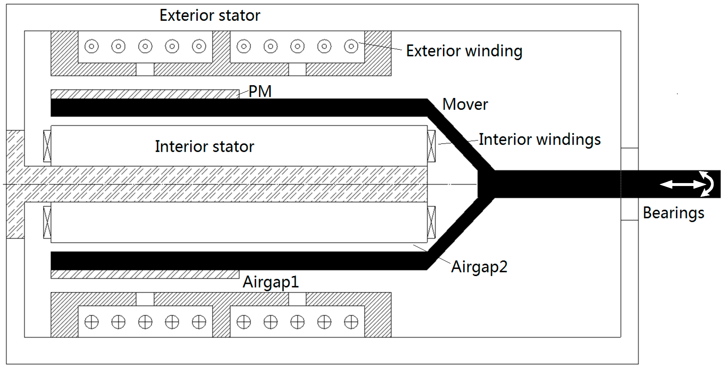
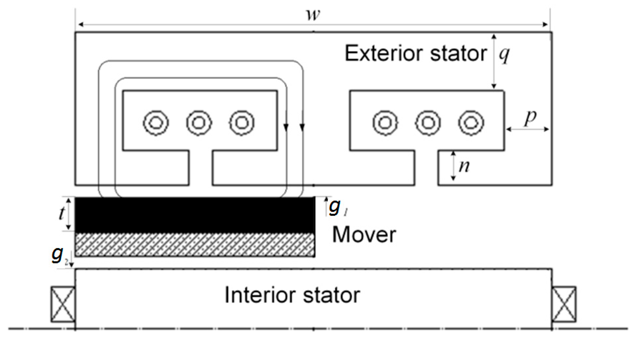
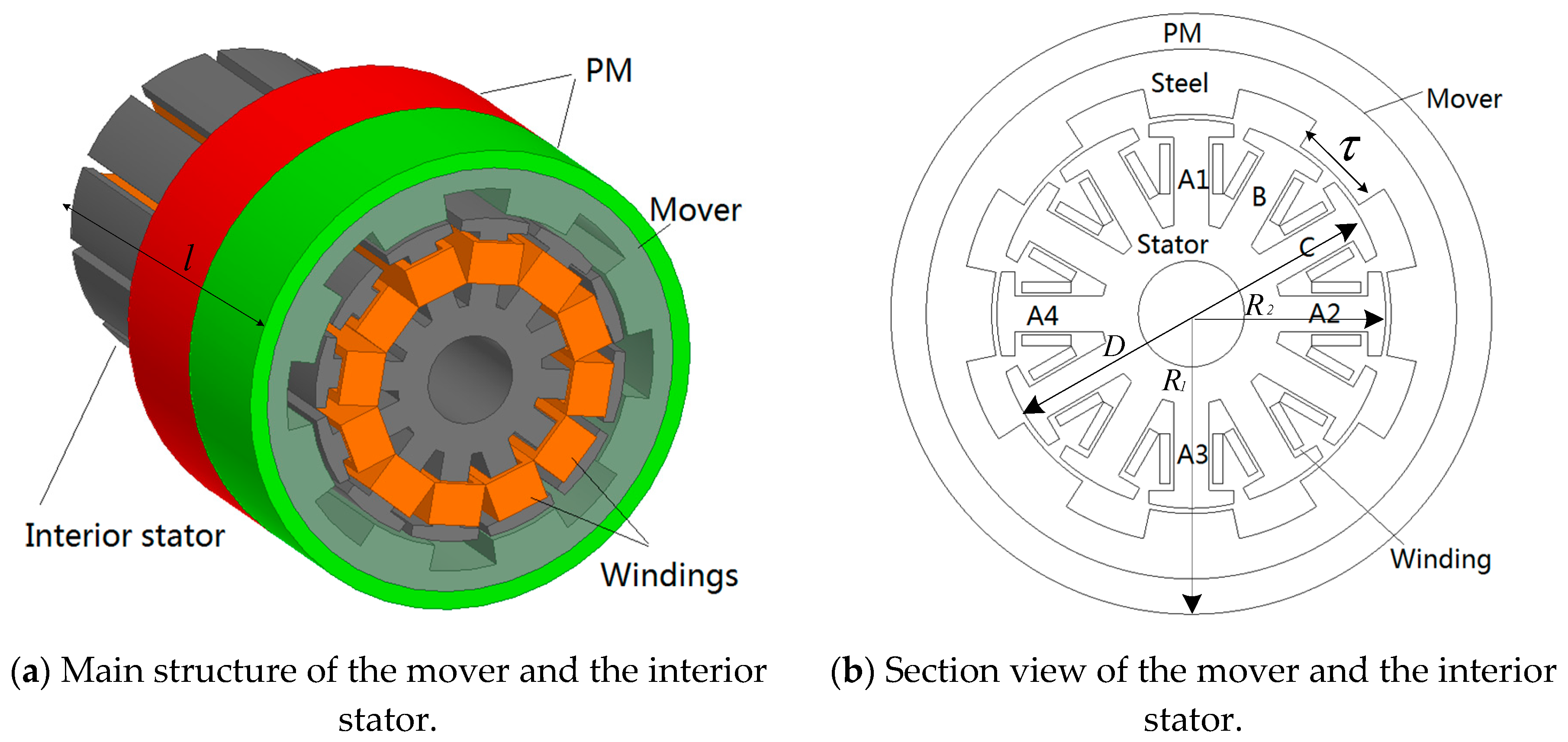
2.1. Mechanical Structure

The mechanical structure of the motor is shown in Figure 1. This motor mainly consists of a mover and two stators. The exterior winding is embraced by the exterior stator that is responsible for the linear movement of the mover, interacting with the PMs mounted on the surface of the mover. The airgap1 exists between the exterior stator and the mover. The interior stator is fixed with the exterior stator by a connector and three windings are fixed on the interior stator. There is an airgap2 between the interior stator and the mover. A torque will generate after the interior windings are excited. The mover is curbed by linear and rotary bearings. When the exterior winding and the interior windings are excited at the same time, the mover will move along the horizontal direction with continuous rotation.
There are two main parts for the motor including the linear part and the rotary part. The linear part of the motor is shown in Figure 2. Two flux lines with black arrows show the magnetic flux generated by the current-carrying winding. The flux linkage produced by the PMs and the winding closes along the exterior stator, the PMs and the mover. The mover can move in the linear direction after the winding is excited. Figure 3a shows the PM structure of the mover and the interior stator. Two PM rings are mounted on the surface of the mover. The polarization direction of one PM points to the center along the radius of the PM circle and another one is along the opposite direction.
The rotary part of the RotLin motor is shown in Figure 3b. This part can be treated as 12/8 switched reluctance motor (SRM). The interior stator possessing twelve poles and each pole is embraced by a coil. All coils are divided into three groups for the rotary part and each group owns four coils, constructing a phase for the rotary part. The four coils are connected in series as a winding of a phase. Main specifications of the motor are listed in Table 1.

2.2. Basic Operation

The flux distribution generated from the PMs of the motor is shown in Figure 4. Figure 4a shows the flux distribution section view for the rotary portion. The interior stator owns twelve poles with embraced coils. Therefore, the rotary potion can be treated as a three-phase SRM motor. If the three-phase windings shown in Figure 3b are excited in sequence, a torque will be produced from the mover of the motor. From the flux lines of the linear portion shown in Figure 4b, A pair of magnetic poles is generated by the PMs and the flux lines close along the mover and the exterior stator. If the winding of the linear portion is excited by a direct current, a linear force can be produced on the mover. If the direction of the phase current reverses, the linear force will change to the opposite direction. Consequently, the linear part can produce linear force for the mover of the motor.

2.3. Dynamic Equations

For the electric terminal of the motor, the dynamic equations for rotary portion and linear portion can be expressed by
V t = e j + i j R j + L j d i j d t ,   j = 1 , 2 , 3 , 4 .
where V t is the terminal voltage of the motor and e is the back electromagnetic force (EMF). i , R and L are winding current, resistance and inductance, respectively. Lower case symbols denote the windings of the motor. The back-EMFs of the linear part and the rotary part can be calculated by
e l = i j d L j d t
e r = k v v
k v is the speed constant in the linear direction and v is the speed. The lower case symbols of back-EMFs represent the linear direction and the rotating movement. Mechanical outputs of the motor can be expressed as
T = T l + D r ω + J d ω d t
F = F l + B l v + M d v d t
T l and F l are load torque and load force. D r and B l are damping coefficients of the motor in the two directions. J and M represent inertias of the mover of the two directions. ω is the angular speed. v is the velocity of the mover in the linear direction.
The electromagnetic torque and force can be calculated by the following equations.
T = 1 2 i j 2 d L j d θ j = 1 , 2 , 3 .
F = k v i j j = 4 .
The constant k v is determined by the structure of the motor and the calculation method will be introduced in the magnetic circuit design of the motor. θ is the angle shift of the mover.

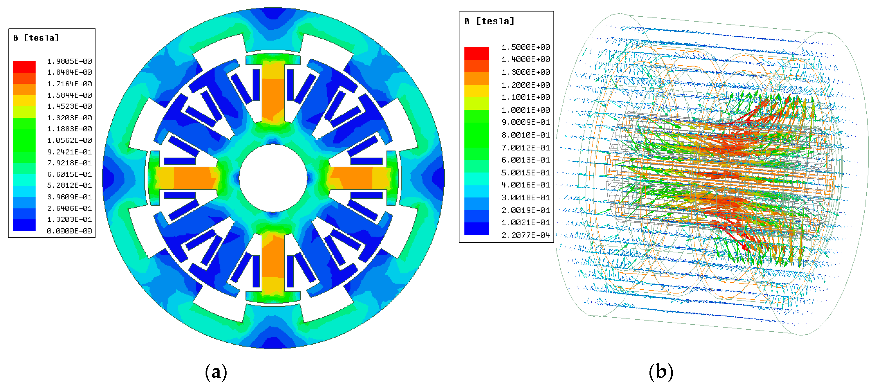
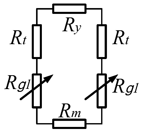
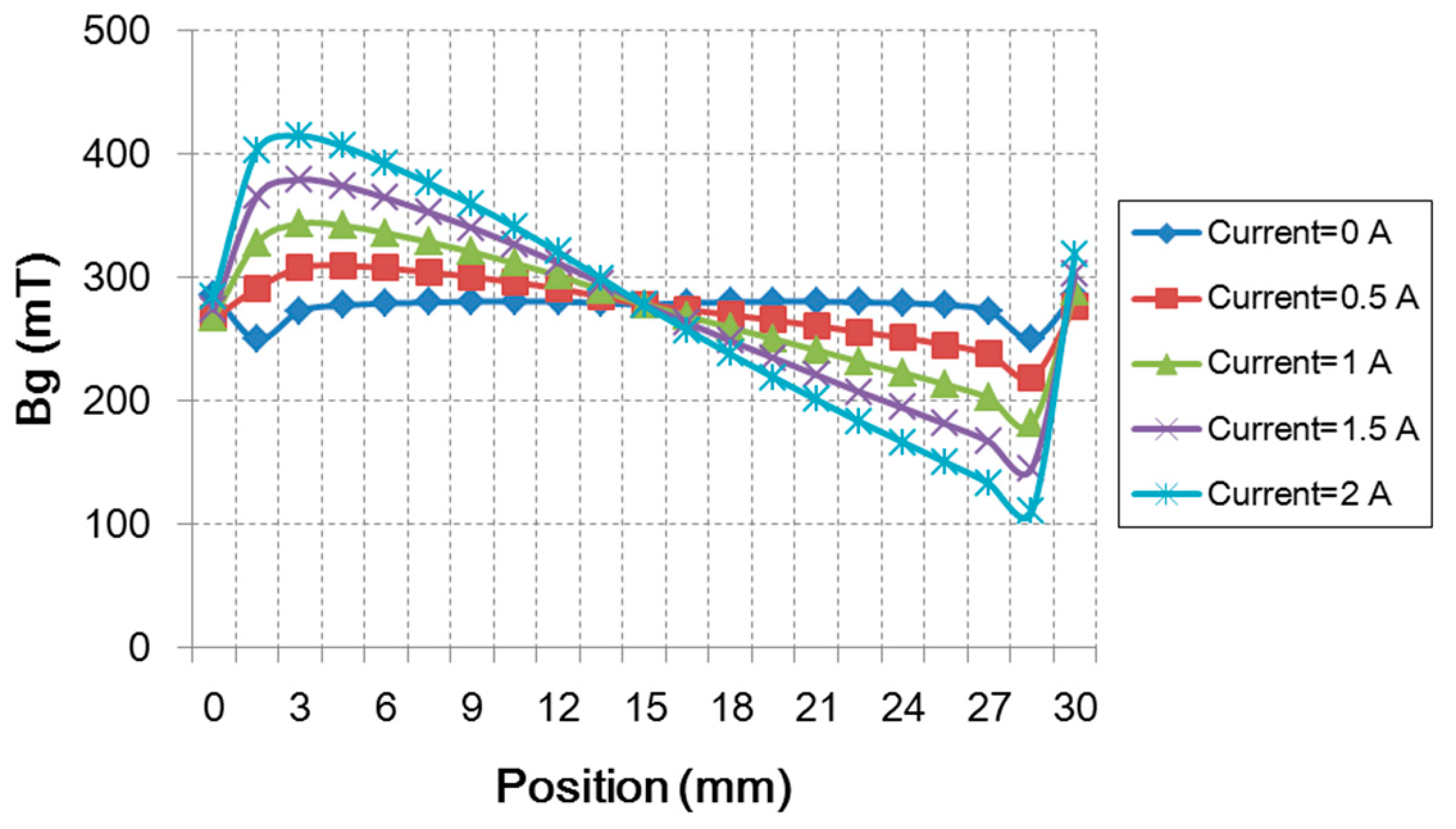
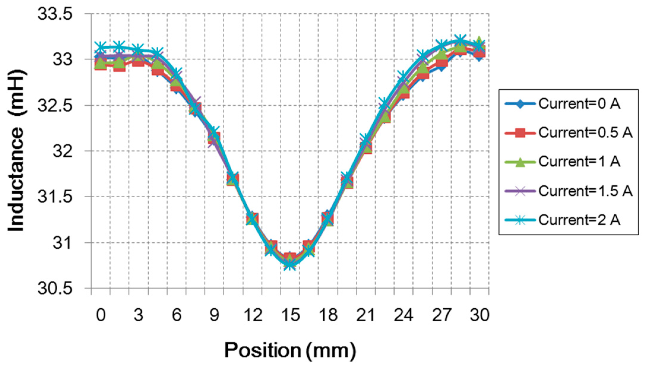
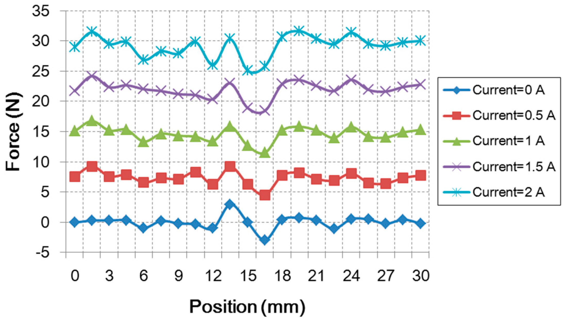
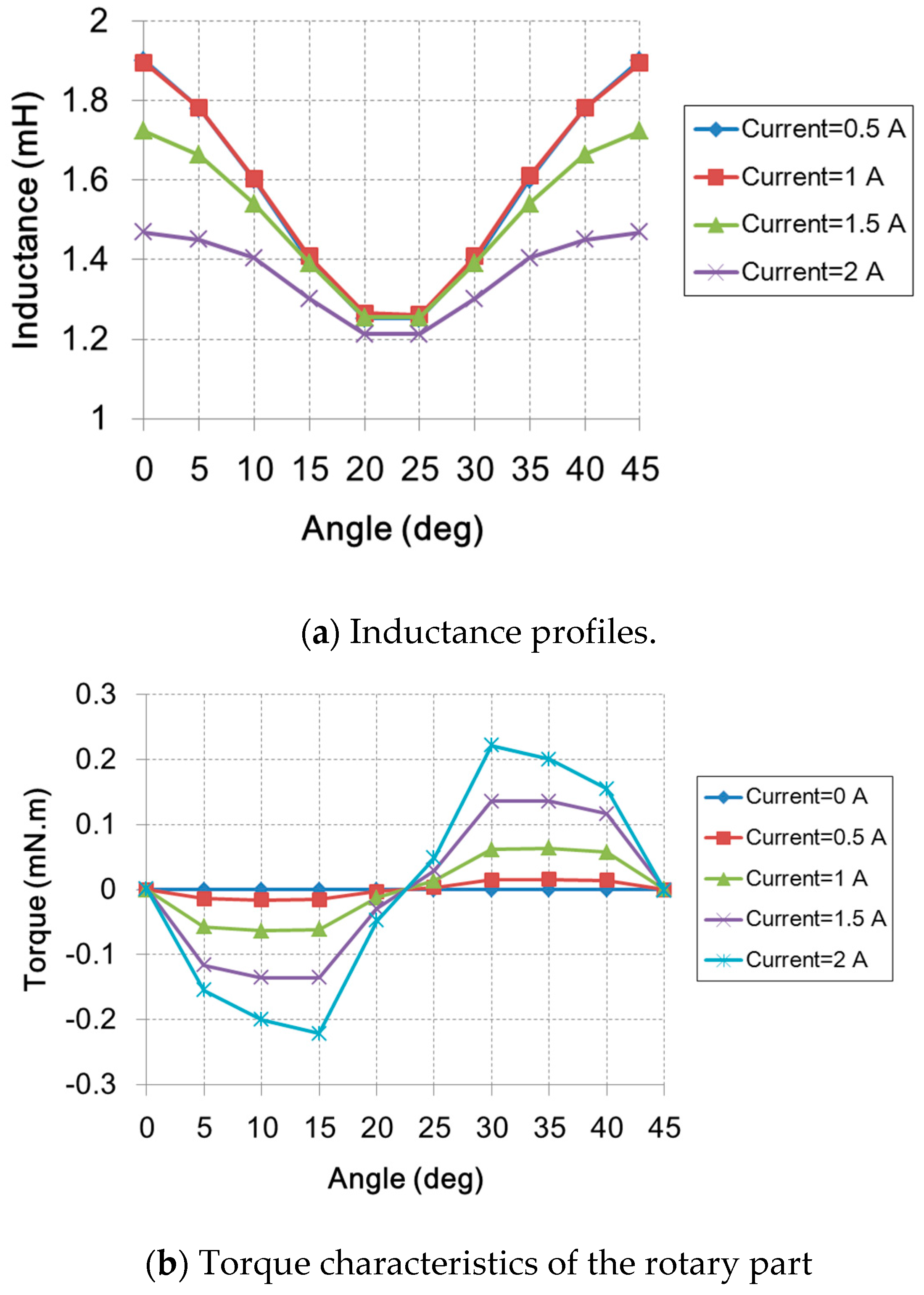
3. Magnetic Circuit Design

When the winding of one phase is excited by square waveform current, ignoring the resistance of the phase winding, the electromagnetic power can be expressed as
P e m = m V t I K d
where V t is the terminal voltage of each winding and I is the phase current, m is the phase number of the rotary part, and Kd denotes the ratio of the conducting region of the phase in one electric period. The voltage equation of each phase is expressed as
λ m = V t ω ( θ o f f θ o n ) = V t ω · θ c
θ o n ,   θ o f f   and   θ c signify the angles of switch on, switch off and conducting angle of the motor respectively. According to the electromagnetic field distribution with a phase excited, it can be seen that the main flux of each pole within the scope of one mover pitch. Therefore, the magnetic load B can be expressed as
B = ϕ τ l
where ϕ is the main flux of each pole and τ is the mover pitch. l is the length of interior stator.
τ = D · π N
D is the diameter of the mover and N is the pole number of the mover.
After determining the magnetic load of the motor, the maximum flux linkage λ m can be written as
λ m = m · ϕ = m · B · D · l · π N
The volume of rotary part can be calculated by
D 2 l = k · 6.1 B · A · P e m ω
k is a coefficient with respect to the conducting period and the angular speed. D 2 l is proportional to the volume of mover as well as the whole volume of the motor. A is the electric load of the rotary part with respect to the current density of winding.
The equivalent magnetic circuit reluctance of the linear part can be shown in Figure 5, according to the structure of Figure 2. Ry is the reluctance of the back iron of the exterior stator and Rt is the reluctance of the poles of the stator. R g 1 is the reluctance of the airgap1. Rm denotes the reluctance of the PMs.
The permeance of the linear part can be calculated as
P l = 1 2 ( R g 1 + R t ) + R y + R m
According to the magnetic permeability, the flux generated by the excited current can be calculated as
l = P l N l i l
P l is the magnetic permeance of the PM. N l and i l   are winding turns and current of the linear portion respectively.
The exterior stator can be regarded as a left part and right part. The magnetic flux in the left part air gap generated by the PMs can be calculated as
L = B r · A m = B r · 2 · π · ( R 2 + g 2 + h + t ) · L x
where B r is the remanence of the PM. L x is the PM length under the left part of the exterior stator. R 2 is the radius of the interior stator. h and t are the thicknesses of the PM and the back iron of the mover. Considering the flux leakage, the magnetic flux of the air gap and the flux density will be
g L = L 1 + P l ( 1 + K d ) R g 1
B g L = g L A g
R g 1 is the magnetic reluctance of the air gap. A g is the section map of the air gap and K d is the flux leakage factor. Similarly, the right part of the stator can also be obtained
g R = R 1 + P l ( 1 + K d ) R g 1
B g R = g R A g
During the effective stroke of the mover, the value of K d is nearly a constant and the magnetic flux generated by the PM for the left part and the right part is almost the same value. Consequently, the flux density in the air gap should be
B m = B g L = B g R
When the exterior winding is excited, the flux density produced by the current can be calculated by
B a = N l I l μ 0 π g 1
where g 1 is the length of the airgap1. The flux density in the air gap of the left part and the right part will be
B g L = B m B a
B g R = B m + B a
If the mover moves a tiny displacement in the linear direction, the thrust force can be calculated by
F = I l · φ x = 2 · π · N l · B m · R 2 · I l
The force factor for the linear movement of the motor can be obtained
k v = 2 · π · N l · B m · R 2
The mechanical power output for the linear movement of the motor can be derived as
P v = F · v
The thicknesses of stator back-iron p   and   q are determined by
p = m 2 · π · ( R 1 t ) · B m a x
q = R 2 R o 2 m π · B m a x
where m and B m a x are the magnetic flux generated by the PM and the limited flux density in the stator back-iron. The thrust force output is mainly affected by the parameters of the PM and the current of the winding. Also, the limitation of the force output will be determined by the size of the motor including the value of p, q, R 2 and R 1 , etc.
The flux density profiles, with respect to different phase current levels of the airgap1, are shown in Figure 6. The flux density can be nearly 280 mT when the linear stator is not excited. When the excitation current rises to the rated current 2 A, the difference of the flux density in the whole stroke of the mover can reach 300 mT, with the maximum value a little bigger than the value of 400 mT. The inductance value experiences a V shape during the stroke when the mover moves from the position zero to the position 30 mm, with the maximum value 33 mH appearing at the beginning and the end point, and the bottom value falling to 30.7 mH at the middle position in the stroke, as shown in Figure 7. The phase current influences a little bit change on the inductance value of the linear part and this influence can be ignored.
The force output profiles under different current excitations of the linear part are shown in Figure 8. There is no force output when the current excitation is zero. When the phase current increases to the rated current 2 A, the force output will be around 30 N. There are some force ripples during the stroke and the obvious ripple occurs at the position 15 mm, where the mover movers from the left part to the right part. The main reason is that the local magnetic flux density saturation occurs when the mover moves to the central part approaching the middle pole of the stator. The ripples can be alleviated by optimizing the thickness of the steel part of the mover and the shape of the stator for the linear part. The thickness of the steel part in the mover plays an important role both for the linear part and the rotating part.
For the rotary part, the inductance value of a winding in one electric period is shown in Figure 9a. The inductance value of the SRM will decrease with the increase of the excitation current. The corresponding torque output of the motor is also shown in Figure 9b. During one electric period, the direction of the reluctance torque will change to the opposite direction when the mover rotates to the unaligned angle. The maximum torque of the rotation part can achieve the value that is slightly bigger than 0.2 mN.m.

4. Control Scheme and Experimental Verification
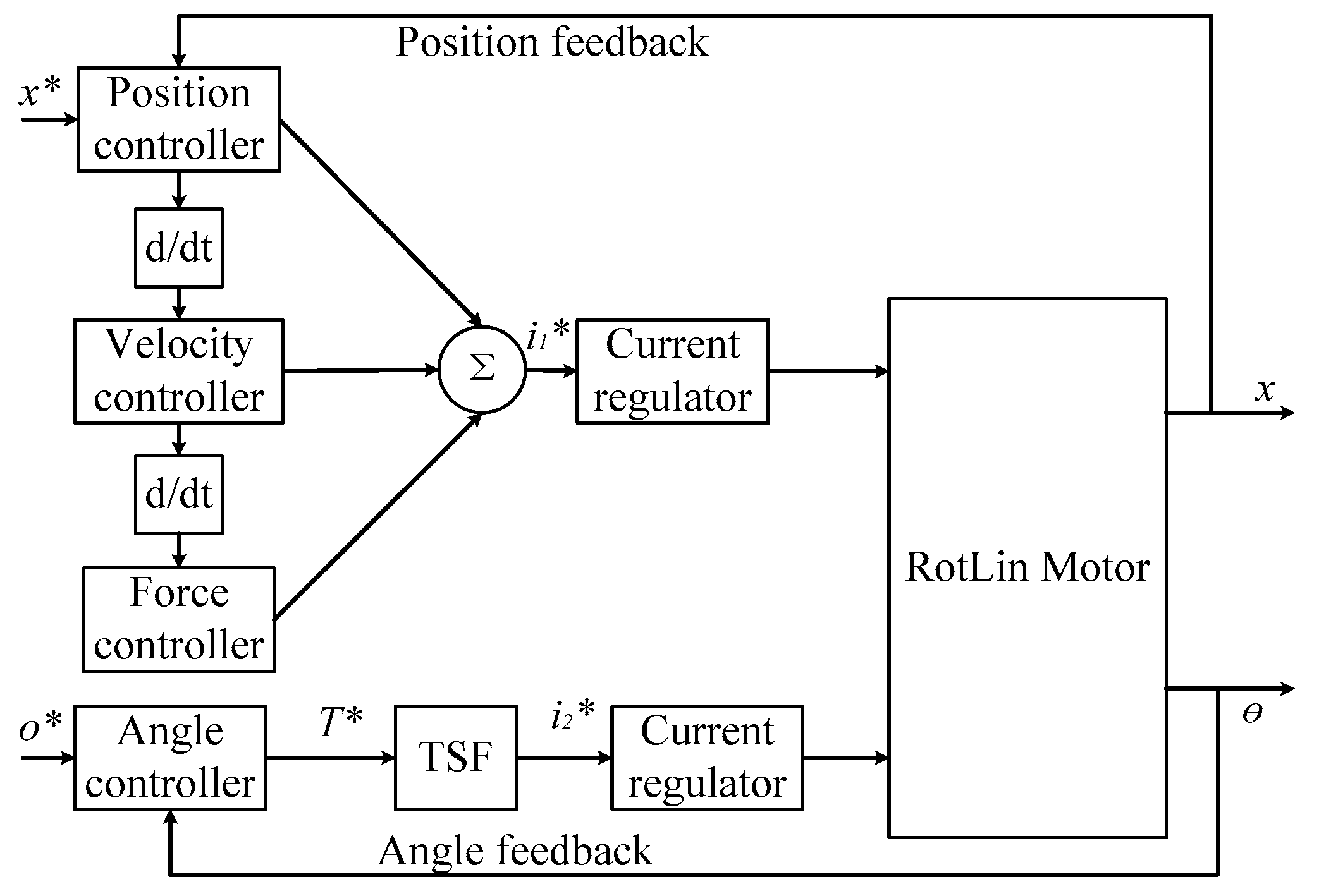
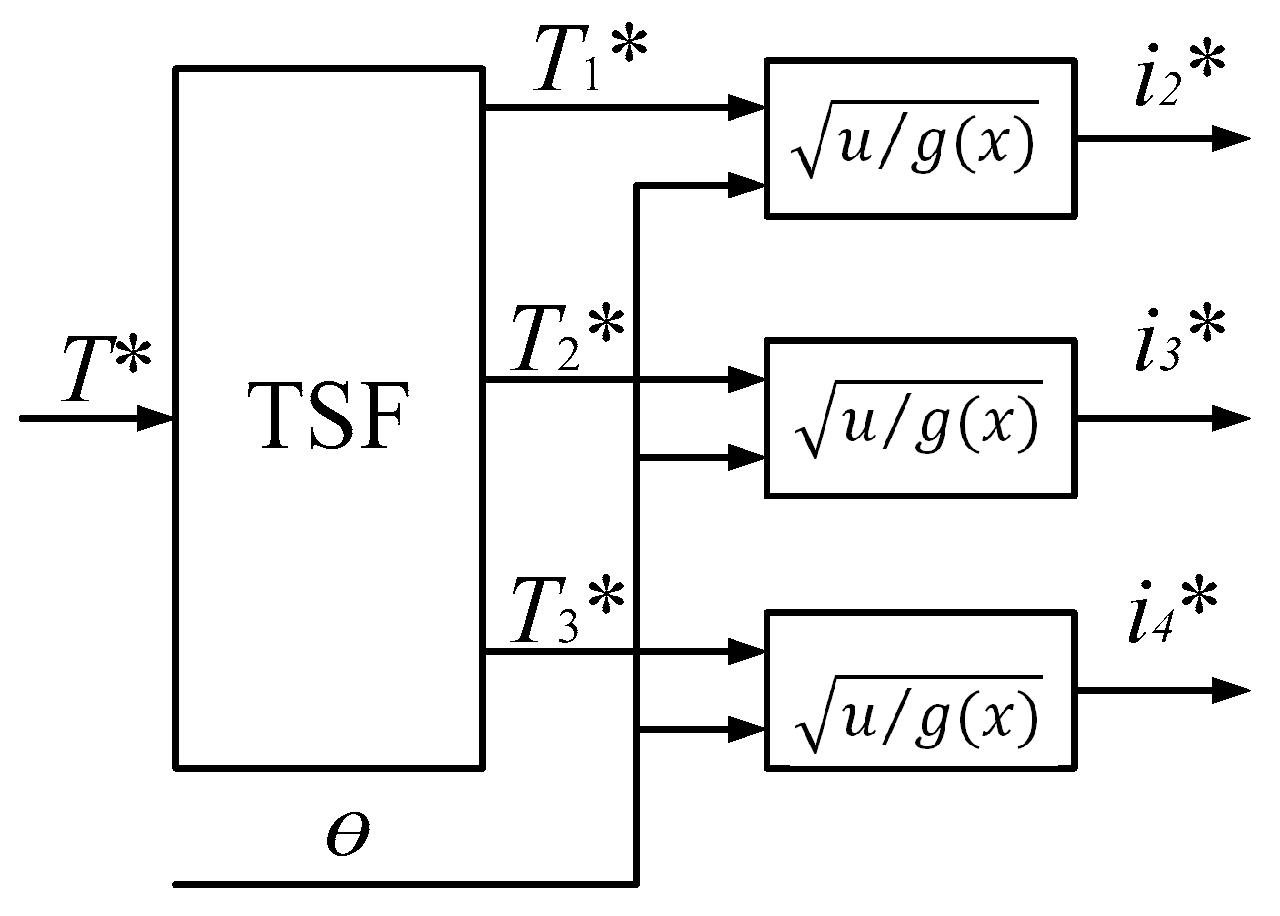
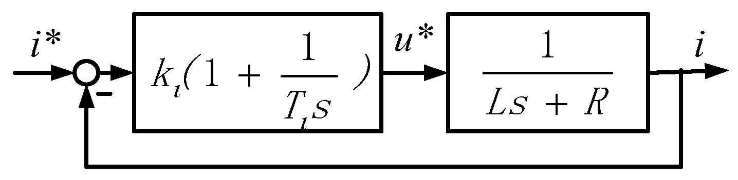
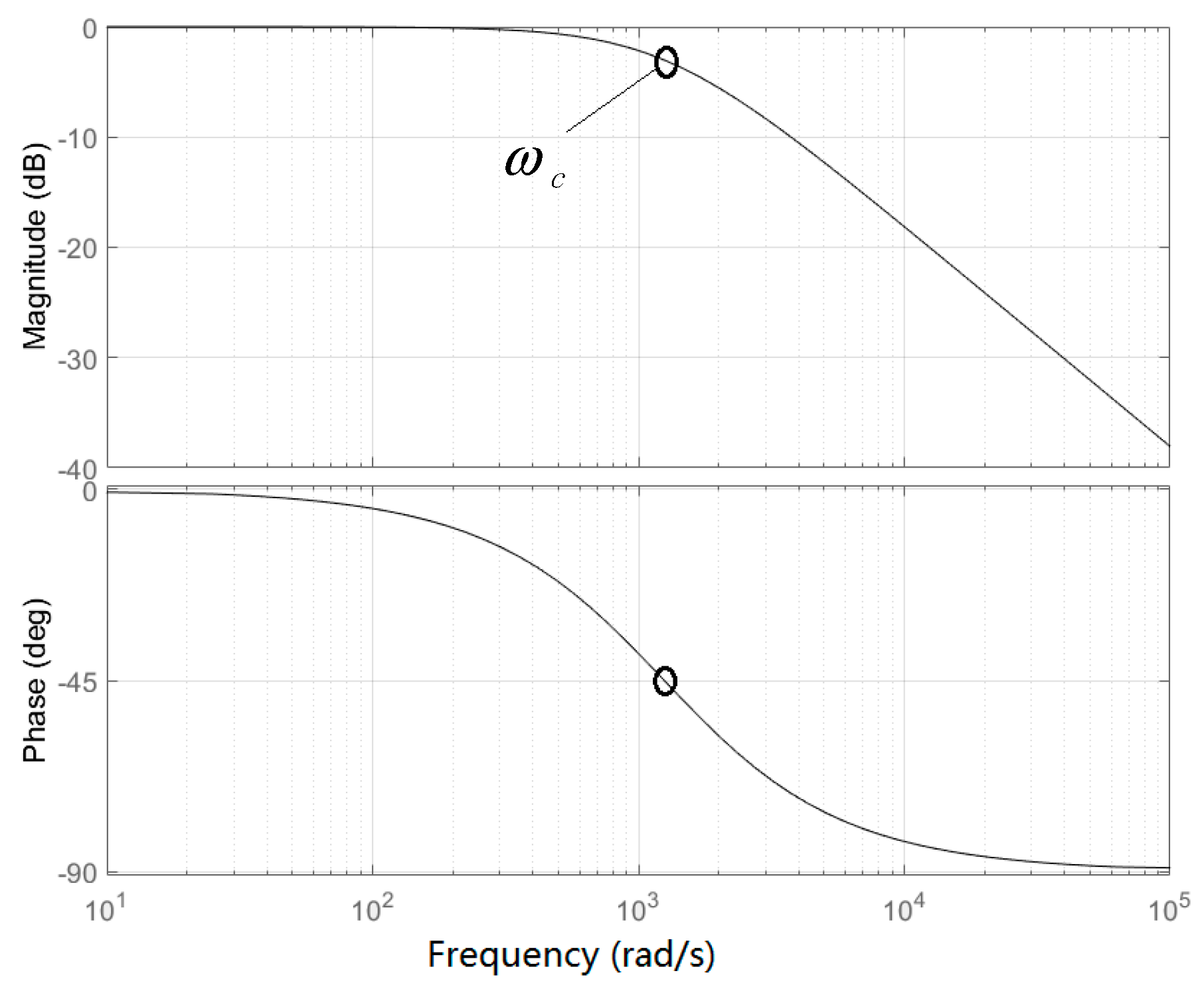
4.1. Control Scheme

The whole control scheme of the motor is shown in Figure 10. This motor can be controlled separately in the linear and rotary directions. The linear movement is realized by a DC drive mode according to the electromagnetic analysis of the motor abovementioned. The position reference and the position feedback are the inputs for the position controller. In order to obtain a precise control in the linear part, three controllers including the position controller, the velocity controller, and the force controller are connected in parallel so that the computation time in one sample period could be shortened to achieve a swift response for the control loop. The sum of the outputs from the three controllers is the reference of a current regulator for the linear movement. For the rotary part, the angle reference and the angle feedback are the inputs for the angle controller. A torque sharing function (TSF) block is designed to assign the torque for each phase of the rotary part and a current regulator is also employed to adjust the current for the rotation of the motor [20,21,22]. The TSF block and the structure of the current regulator are shown in Figure 11 and Figure 12. All controllers in the control scheme are PI control.
As adjacent phases of the rotary part have common conducting regions, a TSF is employed to alleviate the torque ripples of the motor, as shown in Figure 11. Three phase currents can be calculated by
i = T 1 2 · L ( i , θ ) θ
then we can obtain
g ( x ) = 1 2 · L ( i , θ ) θ
The current regulator block consists of a closed control loop to control the phase current. A PI controller is used in this closed loop to supply the voltage reference for the phase winding of the motor. According to the current regulation block diagram in Figure 12, the open transfer function of the current regulator will be
G o ( s ) = k i ( 1 + 1 T i s ) L s + R
where k i is the amplifier coefficient of the current regulator and T i is the time constant of the integral control. The zero and the pole of the open transfer function are usually neutralized in the control loop. Therefore the integral time constant will be
T i = L R
Then the open loop transfer function and closed loop transfer function are
G o ( s ) = k i L s
G c ( s ) = 1 L k i s + 1
The cross frequency of the current regulator can be obtained as
ω C = k i L
and this value can be found in the current regulator of the closed loop transfer function in a Bode diagram, as shown in Figure 13. If the cross frequency and the inductance value of the winding are obtained, the coefficient k i can be set for the current regulator.

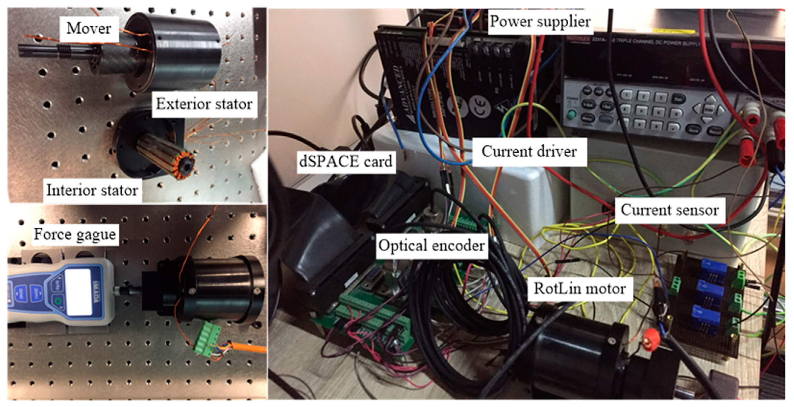
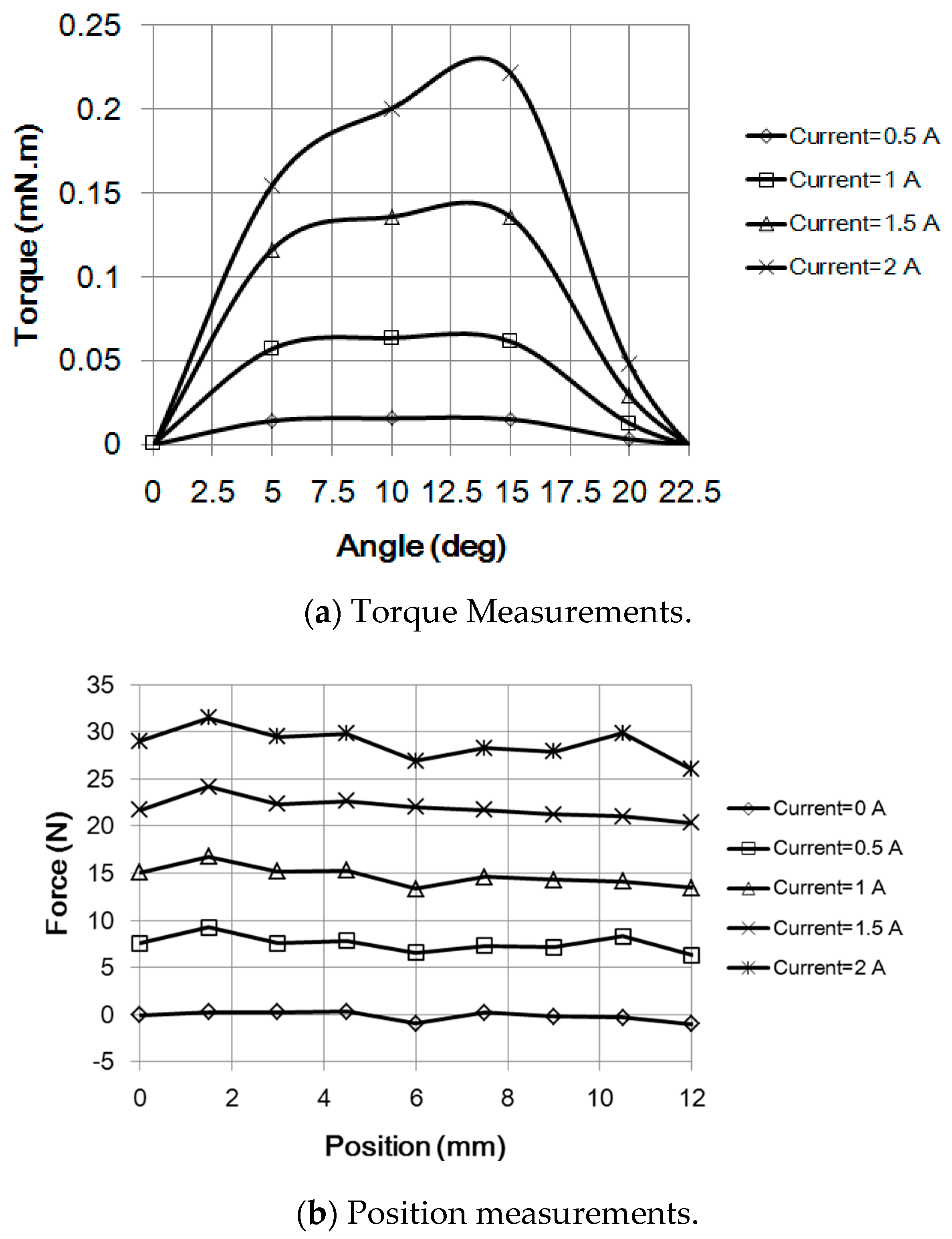
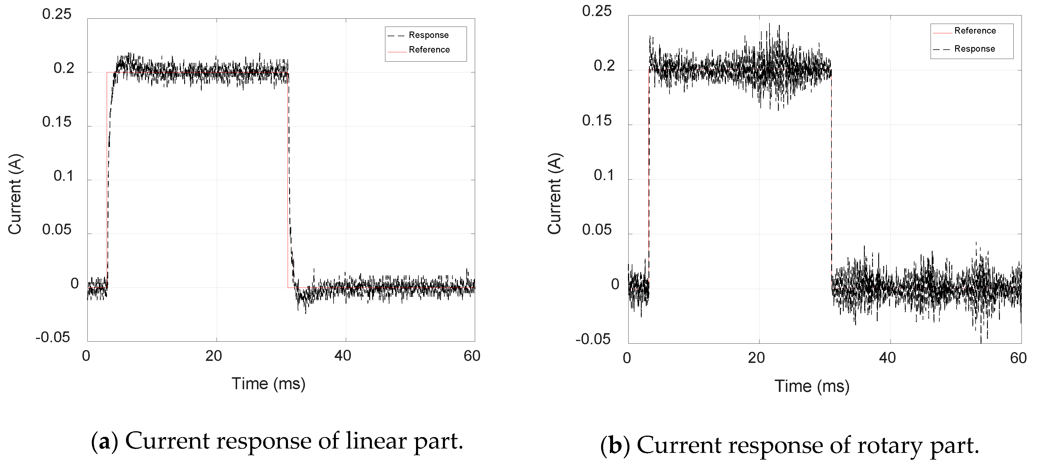
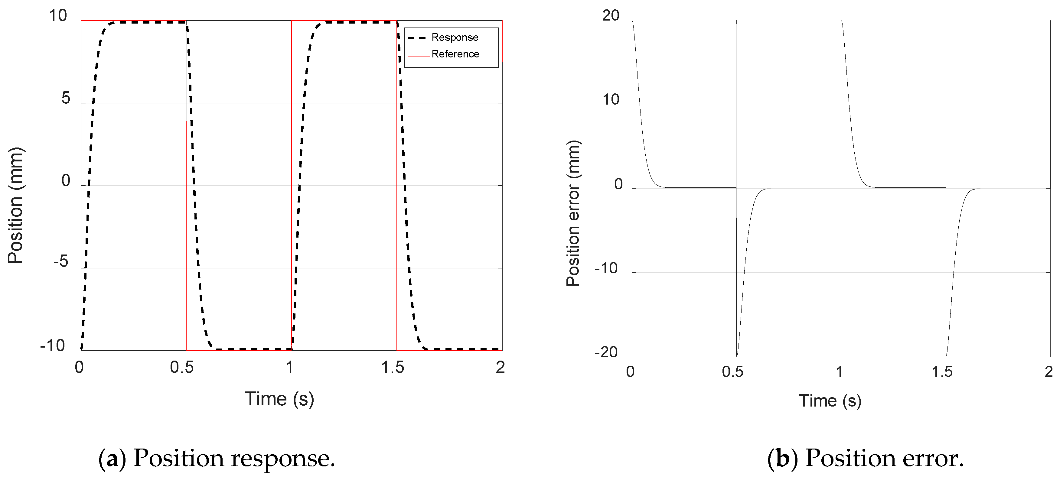
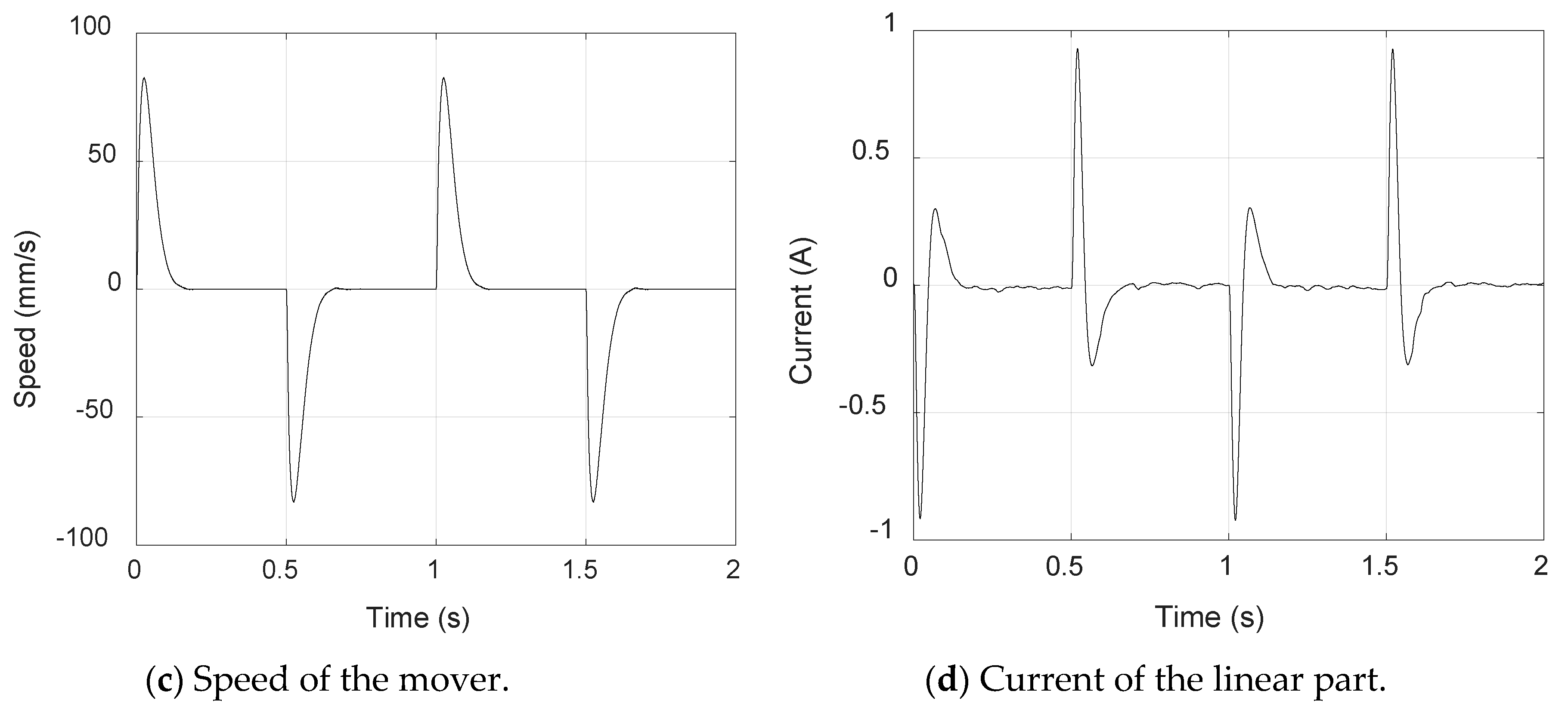
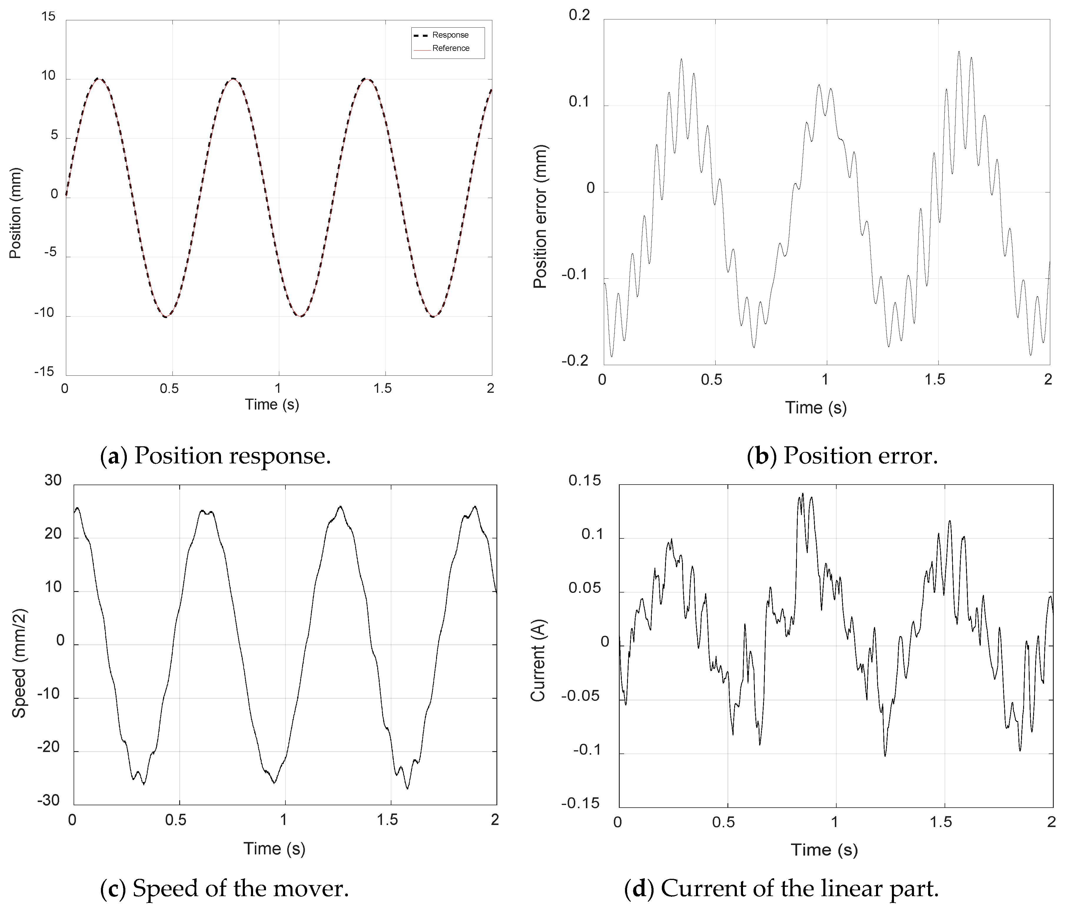
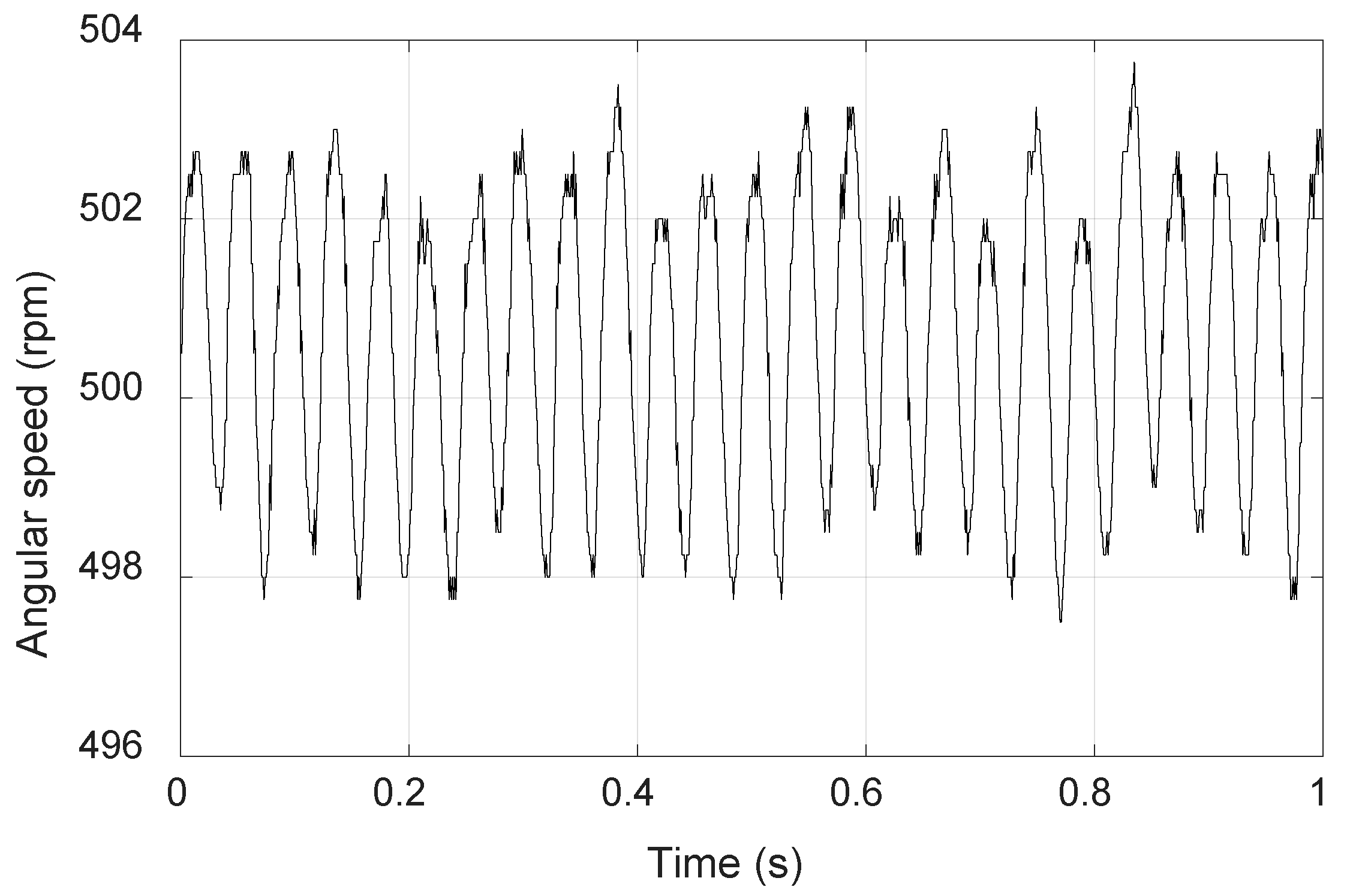
4.2. Experimental Results

The experimental setup is built by a hardware simulation system dSPACE card DS1104, as shown in Figure 14. This card is regarded as a control microprocessor and it can be programmed according to simulation blocks built from MATLAB/Simulink. Besides the control card, the setup includes current drivers, current sensors (LEM CASR-6-NP), force and torque gauges (HIOS digital torque meter and IMADA DST-50N), a linear optical encoder and a rotary optical encoder (RENISHAW) and the motor prototype. Encoders are used to measure the position and angle of the two axes for the motor and current sensors are used to feedback phase currents of the motor to the control card. Finally, according to feedback information, the control card will output the current commands for the current drivers connected with the motor, constructing a closed loop control. Torque and force measurements are carried out and the results are shown in Figure 15 and the results prove the validity of the FEM calculation.
Current responses of the linear part and the rotary part regulated by the current loop control are shown in Figure 16. When the power supplier is 24 V and the current reference is a rectangular pulse rising from zero to 0.2 A at 3 ms and falling to zero at 30 ms, the current response of the linear part has little ripples within ±0.02 A. Under the identical condition, current ripples are obvious for the rotary part. It can be seen that the enclosed line of the current ripples is a sine-like wave. This is mainly caused by the inductance change of windings of the rotary part at different angles. The phase current is hard to regulate with little ripple for SRMs due to the varied inductance at different angles, compared with motors that own a constant inductance.
When the position reference of the motor is a rectangular wave with an amplitude of 10 mm and a frequency of 1 Hz, the position response is shown in Figure 17a and the position error line is shown in Figure 17b, followed by the corresponding speed wave and phase current of the motor in Figure 18c,d, respectively. The rectangular position tracking performance well and the positioning accuracy of the motor can reach 4 µm. The peak phase current is up to 1 A with no load when the motor accelerates from zero to 80 mm/s within 0.03 second. When the position reference is a sine wave with the amplitude of 10 mm and a frequency of 1.625 Hz, the responses of the motor are shown in Figure 18. The position error exceeds 0.1 mm when the motor movers according to the sine wave reference. The speed response and phase current have some ripples. The parameters of PI controllers are listed in Table 2. As the controller is designed by PI control, the parameters of the controller are not totally suitable for the entire operation conditions of the motor. It is obvious that the motor performance is worsening when the position reference changes from a rectangular wave to a sine wave.
The angular speed response of the motor is shown in Figure 19 when the speed reference is 500 rpm. The results show that the steady state error of the speed is within 3 rpm at this speed reference. The magnetic coupling effect between the linear part and the rotary part could deteriorate the performance of the motor both in the two axes. However, in the discussion part, the FEM result of the mutual inductance of the two axes can be ignored. Modifying the control method for the motor is necessary to improve the performance of the motor.

5. Discussion

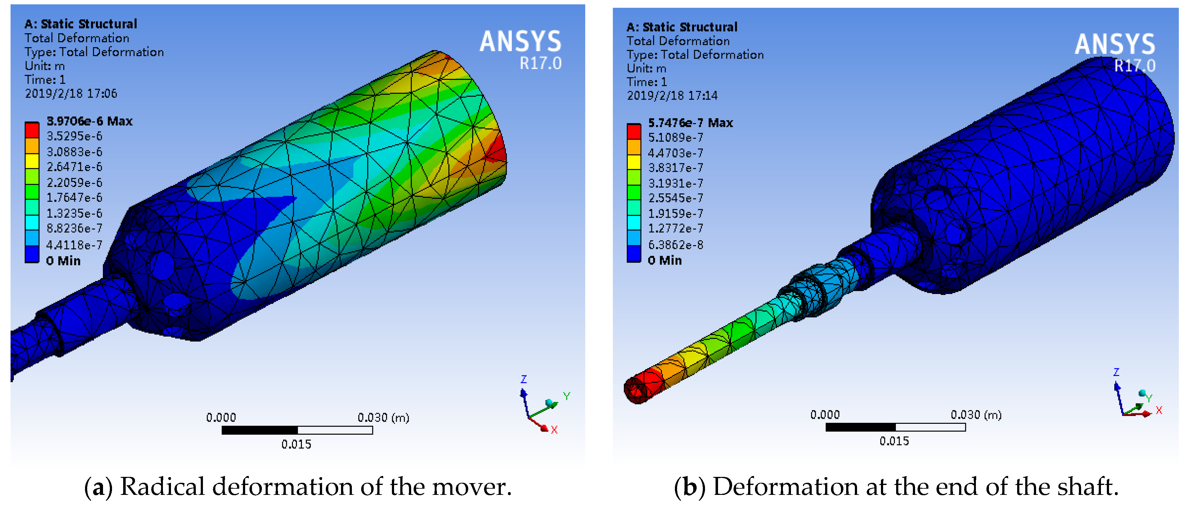
5.1. Deformation of the Mover

According to FEA, the radical force on the mover and the maximum force along the shaft on the end of the moving shaft are obtained as shown in Figure 20a,b. The radical force on the surface of the mover is around 100 N and the maximum force at the end of the moving shaft is 30 N. The material of the mover is steel containing 0.2% carbon. It can be seen that the radical deformation of the mover is up to 4 µm and the maximum deformation on the end of the moving shaft along the shaft is less than 0.6 µm. The air gap length of the mover between two stators is 0.5 mm. This deformation puts little influence on the electromagnetic force outputs and torque outputs so that this influence can be negligible. If the ending surface of the moving shaft is impressed by 30 N, the linear accuracy can achieve 1 µm theoretically as the deformation disturbance is less than 0.6 µm.

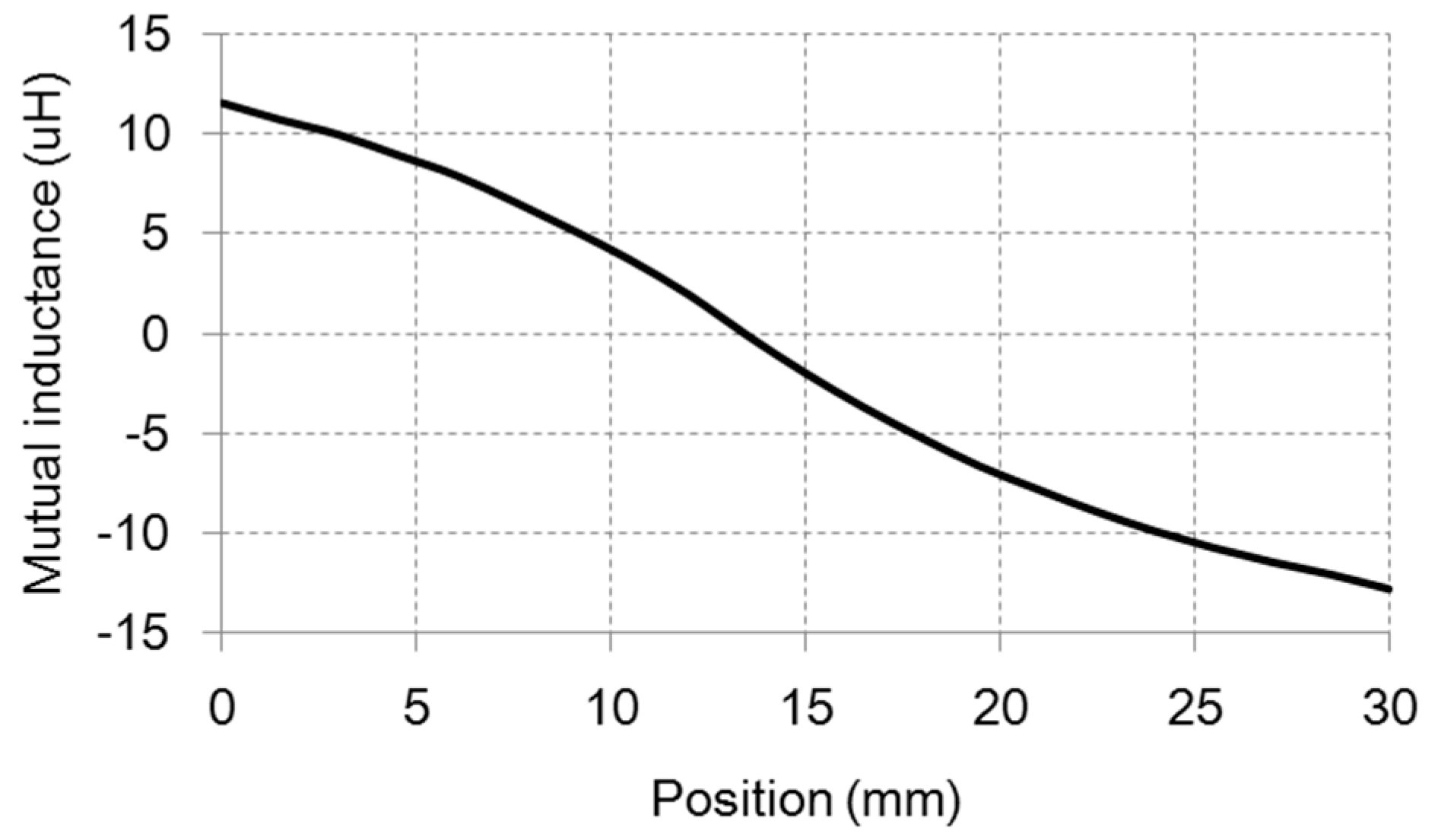
5.2. Decoupling Effect between the Linear Movement and the Rotational Part

The mutual inductance between the windings which are respectively responsible for the linear movements and the rotation part is a good indication to reflect the coupling effect of the motor. When the mover moves in the linear direction from zero to 30 mm, the mutual inductance is shown in Figure 21. The mutual inductance is less than the value of 15 µH according to the result. This value is significantly less than that of the self-inductance of the windings, compared with values from Figure 8 and Figure 10. This result shows that the mutual inductance between the windings for the linear part and the rotational part is far less than their self-inductance value. Therefore, the coupling effect between the linear part and the rotational part can be also negligible.

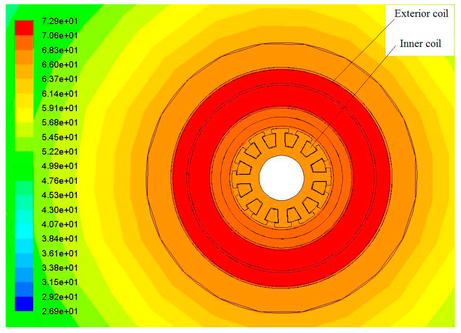
5.3. Thermal Field Discussion of the Motor

The ambient temperature of the motor is obtained by FEM as shown in Figure 22. It can be seen from the figure that the highest temperature appears at the outside coil of the exterior stator and the teeth of the stator. The temperature is up to 73 degrees centigrade. The temperature of the outside crust and the interior stator is about 64 degrees centigrade. The ambient temperature of the mover is 66 degrees centigrade. which is lower than that of the stator and a litter bit higher than that of the interior stator.

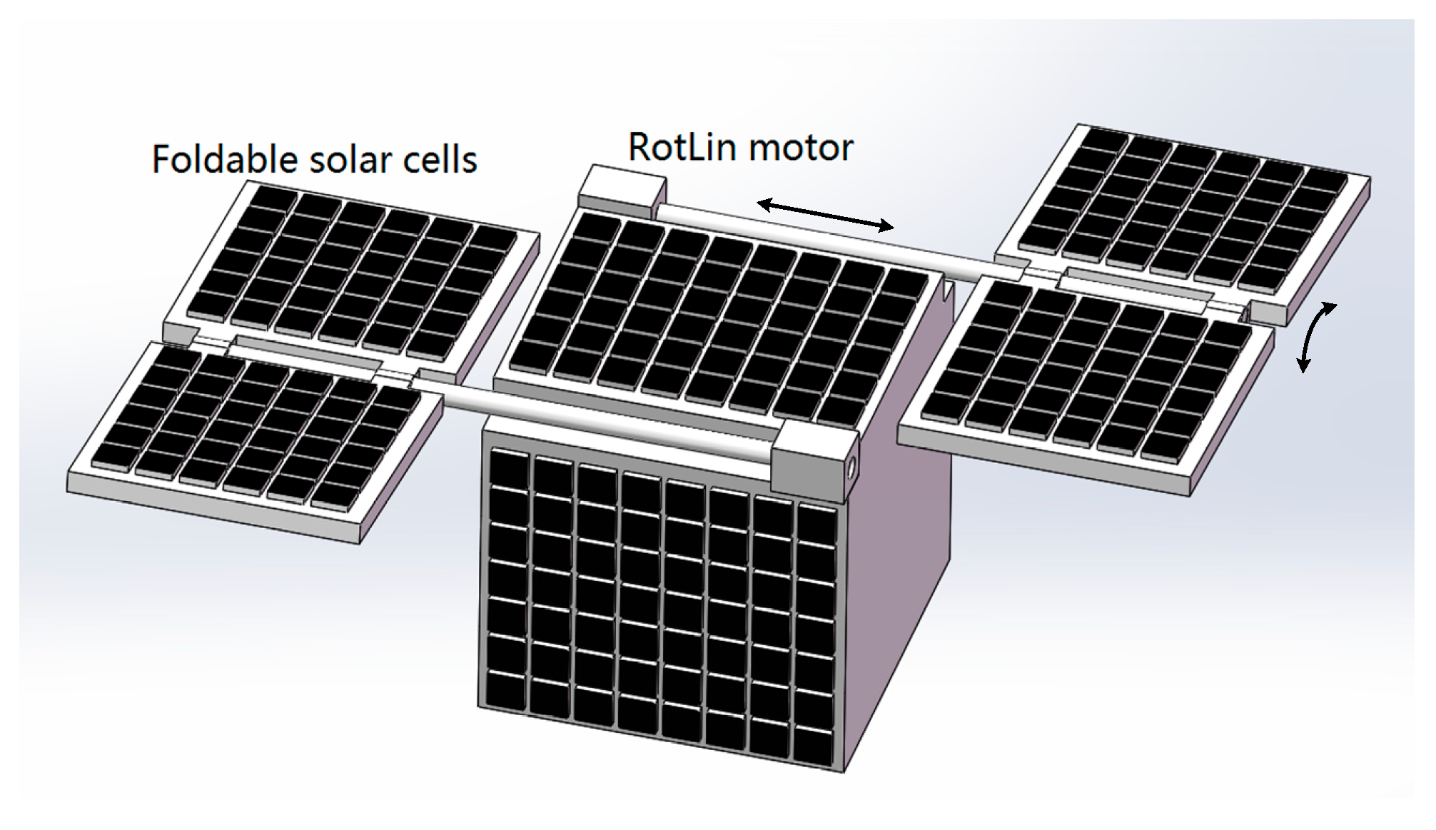
5.4. New Foldable Photovoltaic Unit with the RotLin Motor

This motor design could be used in next generation photovoltaic units shown in Figure 23. The solar cells can be folded so that the space of the power generation unit can be saved during the idle time of the unit. When the solar cells track the sun, the RotLin motor will rotate to the angle where the surface of solar cells is perpendicular to the sunlight. Also, the foldable solar cells can be folded when the motor rotates and moves to the surface of the box by the linear movement during snowing or windy days. Therefore, this motor is employed to track the sun and transform the structure of the foldable solar cells in this application.

6. Conclusions

In this paper, an integrated RotLin motor is proposed and designed. The motor structure, operation principles are introduced, followed by detailed design procedure both on the linear part and the rotary part of the motor. Magnetic circuit analysis confirms the feasibility of the simple structure of the motor. The FEM resulted has verified linear force outputs and rotational torque outputs simultaneously. More importantly, a control scheme for the motor is given and corresponding experimental results show that the effectiveness of the designed motor. The positioning accuracy can reach 0.4 µm and the steady speed error is within in 3 rpm. Analysis on the deformation of the mover and the coupling effect between the linear part and the rotary part is carried out by simulation, which suggests that the motor can be a promised integrated RotLin motor to realize precise motion control. The main contributions of this study include: (1) A new simple structure of an integrated RotLin motor is proposed. As the structure is simple, the motor is highly suitable for large scale manufacture in a cost-effective way. (2) A control scheme with experimental verification is given. This control method can be employed by many basic industrial applications in the future. A further study is necessary for this motor to improve the control accuracy of the two axes and this can benefit more industrial instruments to simplify their structures and reduce their periodical maintenance.

Author Contributions

Y.Z. developed the analysis, hardware design and measurement. He also conducted the simulation of the work. K.W.E.C. was responsible for the background theory. He also provided the guidance and supervision of the study.

Funding

This research was funded by Research Committee of the Hong Kong Polytechnic University, grant numbers H-ZDB9 and 845G.

Conflicts of Interest

The authors declare no conflict of interest.

References

  1. Teo, T.J.; Yang, G. Linear Rotary Electromagnetic Actuator. U.S. Patent 2012/0262259 A1, 18 October 2012. [Google Scholar]
  2. Teo, T.J.; Zhu, H.Y.; Chen, S.L. Principle and Modeling of a Novel Moving Coil Linear-Rotary Electromagnetic Actuator. IEEE Trans. Ind. Elctro. 2016, 63, 6930–6940. [Google Scholar] [CrossRef]
  3. Lu, B.L.; Xu, Y.L. Development and Analysis of a Novel Spherical 2-Degree-of-Freedom (2-DOF) Hybrid Stepping Motor. Energies 2018, 11, 41. [Google Scholar]
  4. Chung, M.J.; Yee, Y.H.; Kim, Y.J. Development of High Precision X-Y Stage Using for Production and Inspection Equipment of Organic Electro Luminescence Display. In Proceedings of the SICE Annual Conference, Takamatsu, Japan, 17‒20 September 2007; pp. 1649–1652. [Google Scholar]
  5. Overboom, T.T.; Jansen, J.W.; Lomonova, E.A. Design and optimization of a rotary actuator for a two-degree of freedom zϕ-module. IEEE Trans. Ind. Appl. 2010, 46, 2401–2409. [Google Scholar] [CrossRef]
  6. Si, J.K.; Feng, H.C.; Ai, L.W. Design and Analysis of a 2-DOF Split-Stator Induction Motor. IEEE Trans. Ener. Conver. 2015, 30, 1200–1208. [Google Scholar] [CrossRef] [Green Version]
  7. Wu, W.; Feng, H.C.; Cheng, Z.P. Rotor Eddy Current Loss Calculation of a 2DoF Direct-Drive Induction Motor. Energies 2019, 12, 1134. [Google Scholar] [CrossRef]
  8. Xie, L.J.; Si, J.K.; Hu, Y.H. Characteristics Analysis of the Motions of the 2-Degree-of-Freedom Direct Drive Induction Motor. IEEE Trans. Ind. Electro. 2019. [Google Scholar] [CrossRef]
  9. Zhang, Z.J.; Zhou, H.B.; Duan, J.A. Design and Analysis of a High Acceleration Rotary-Linear Voice Coil Motor. IEEE Trans. Magn. 2017, 53. [Google Scholar] [CrossRef]
  10. Pan, J.F.; Zou, Y.; Cheung, N.C. Performance analysis and decoupling control of an integrated rotary–linear machine with coupled magnetic paths. IEEE Trans. Magn. 2014, 50. [Google Scholar] [CrossRef]
  11. Xu, L.; Lin, M.Y.; Fu, X.H. Orthogonal magnetic field analysis of a double-stator linear-rotary permanent magnet motor with orthogonally arrayed permanent magnets. IEEE Trans. Magn. 2017, 53. [Google Scholar] [CrossRef]
  12. Sato, Y.; Murakami, K.; Tsuboi, Y. Sensorless torque and thrust estimation of a rotational/linear two degrees-of-freedom switched reluctance motor. IEEE Trans. Magn. 2016, 52. [Google Scholar] [CrossRef]
  13. Liu, C.T.; Chiang, T.S. Design and performance evaluation of a micro linear switched-reluctance motor. IEEE Trans. Magn. 2004, 40, 806–809. [Google Scholar] [CrossRef]
  14. Li, S.Y.; Cheng, K.W.E.; Cheung, N.; Zou, Y. Design and Control of a Decoupled Rotary-Linear Switched Reluctance Motor. IEEE Trans. Energy Convers. 2018, 33, 1363–1370. [Google Scholar] [CrossRef]
  15. Zou, Y.; Cheng, K.W.E.; Hu, J.F. A new decoupled RotLin motor with fuzzy sliding mode control. IEEE Trans. Magn. 2018, 54. [Google Scholar] [CrossRef]
  16. Xu, L.; Lin, M.Y.; Fu, X.H. Design and Analysis of a Double-Stator Linear–Rotary Permanent-Magnet Motor. IEEE Trans. Appl. Supercon. 2016, 26. [Google Scholar] [CrossRef]
  17. Pham, T.T.; Vu, N.H.; Shin, S.Y. Novel Design of Primary Optical Elements Based on a Linear Fresnel Lens for Concentrator Photovoltaic Technology. Energies 2019, 12, 7. [Google Scholar] [CrossRef]
  18. Wang, H.; Huang, J.; Song, M.J.; Hu, Y.X.; Wang, Y.F.; Lu, Z.J. Simulation and Experimental Study on the Optical Performance of a Fixed-Focus Fresnel Lens Solar Concentrator Using Polar-Axis Tracking. Energies 2018, 11, 4. [Google Scholar] [CrossRef]
  19. Morón, C.; Ferrández, D.; Saiz, P.; Vega, G.; Díaz, J.P. New Prototype of Photovoltaic Solar Tracker Based on Arduino. Energies 2017, 10, 9. [Google Scholar] [CrossRef]
  20. Pan, J.F.; Cheung, N.C.; Zou, Y. An Improved Force Distribution Function for Linear Switched Reluctance Motor on Force Ripple Minimization with Nonlinear Inductance Modeling. IEEE Trans. Magn. 2012, 48, 3064–3067. [Google Scholar] [CrossRef]
  21. Xue, X.D.; Cheng, K.W.E.; Ho, S.L. Optimization and Evaluation of Torque-Sharing Functions for Torque Ripple Minimization in Switched Reluctance Motor Drives. IEEE Trans. Power Electron. 2009, 24, 2076–2090. [Google Scholar] [CrossRef]
  22. Xue, X.D.; Cheng, K.W.E.; Bao, Y.J.; Leung, P.L.; Cheung, N. Switched Reluctance Generators with Hybrid Magnetic Paths for Wind Power Generation. IEEE Trans. Magn. 2012, 48, 3863–3866. [Google Scholar] [CrossRef]
Figure 1. Section view of the mechanical structure.
Energies 12 01983 g001
Figure 2. Magnetic structure of the linear part.
Energies 12 01983 g002
Figure 3. The structure of the rotary part (a) and its section view (b).
Energies 12 01983 g003
Figure 4. The flux distribution of the motor for. (a) the rotational movement section view and (b) the linear movement section view.
Energies 12 01983 g004
Figure 5. The equivalent magnetic circuit of the linear part.
Energies 12 01983 g005
Figure 6. Air gap flux density corresponding to the position of the mover.
Energies 12 01983 g006
Figure 7. Inductance profiles of the winding responsible for the linear part.
Energies 12 01983 g007
Figure 8. Force outputs of the mover under different phase currents.
Energies 12 01983 g008
Figure 9. Inductance values and torque outputs under different excitations.
Energies 12 01983 g009
Figure 10. Control scheme of the RotLin motor.
Energies 12 01983 g010
Figure 11. Torque sharing function block for the rotary part.
Energies 12 01983 g011
Figure 12. Transfer function block of the current regulator.
Energies 12 01983 g012
Figure 13. Bode diagram of the current regulator.
Energies 12 01983 g013
Figure 14. Mechanical parts of the motor and experimental setup.
Energies 12 01983 g014
Figure 15. Torque and force measurement of the motor with different current excitations.
Energies 12 01983 g015
Figure 16. Current loop responses of the motor when the reference is 0.2 A.
Energies 12 01983 g016
Figure 17. Position responses of the motor under a rectangular wave reference.
Energies 12 01983 g017aEnergies 12 01983 g017b
Figure 18. Responses of the motor under a sinusoidal wave reference.
Energies 12 01983 g018
Figure 19. Angular speed response of the motor under the reference of 500 rpm.
Energies 12 01983 g019
Figure 20. Deformation of the mover in the radium direction (a) and along the shaft direction (b).
Energies 12 01983 g020
Figure 21. The mutual inductance value of the windings of the linear direction and the windings responsible of the rotation.
Energies 12 01983 g021
Figure 22. Ambient temperature of the RotLin motor.
Energies 12 01983 g022
Figure 23. New foldable solar generation with the designed RotLin motor.
Energies 12 01983 g023
Table 1. The main specifications of the motor.
SpecificationsQuantity (SI)
Rated power of linear part30 W
Rated current of the motor ( I l , I )2 A
Diameter of interior stator (D)22 mm
Radium of mover (R1)17 mm
Pole pitch of mover ( τ )4.8 mm
Stack length of interior stator (l)60 mm
Length of exterior stator (w)60 mm
Back iron thickness of exterior stator (q)3 mm
Size of PM2 × 17 × 30 mm
Pole width of exterior stator (p)4 mm
Rated power of rotary part ( P e m )20 W
Mass of mover (M)169.8 g
Thickness of exterior stator(q)3.5 mm
Length of air gap 1 (g1)0.5 mm
Length of air gap 2 (g2)0.5 mm
Linear winding turns ( N l )250
Rotational winding turns (N) 12 × 12
Linear encoder accuracy 1 μm
Rotational encoder lines81,920
Table 2. The parameters of controllers.
SpecificationsValue
Propotional gain of postion controller2
Intergral gain of position controller0.01
Propotional gain of speed controller0.1
Intergral gain of speed controller0.003

