Article

A Proportional Plus a Hysteretic Term Control Design: A Throttle Experimental Emulation to Wind Turbines Pitch Control

Department of Mathematics, Universitat Politècnica de Catalunya (UPC), 08222 Terrassa, Spain
Energies 2019, 12(10), 1961; https://doi.org/10.3390/en12101961
Submission received: 4 May 2019 / Revised: 17 May 2019 / Accepted: 20 May 2019 / Published: 22 May 2019

Abstract

:
Pitch control is a relevant issue in wind turbines to properly operate the angle of the blades. Therefore, this control system pitches the blades usually a few degrees every time the wind changes in order to keep the rotor blades at the required angle thus controlling the rotational speed of the turbine. All the same time, the control of the pitch angle is not easy due to the system behavior being highly nonlinear. Consequently, the main objective of this paper is to depict an easy to implement control design based on a proportional controller and a hysteretic term to an emulator pitch control system in wind turbines. This emulator is just an automotive throttle device. This mechanical body dynamically captures some hard non-linearities presented in pitch wind turbine mechanisms, such as backlash, asymmetrical non-lineal effects, friction, and load variations. Even under strong non-linear effects that are difficult to model, a proportional controller and a hysteretic term may satisfy the main control design objective. Hence, a recent control design is developed and applied to a throttle system. We invoke the Lyapunov theory to confirm stability of the resultant closed-loop system. In addition, the proposed control approach is completely implemented by using operational amplifiers. Hence, no digital units are required at all. Moreover, the cost of the developed experimental platform and its outcomes are inexpensive. According to the experimental results, the controller performance seems acceptable, and validating of the control contribution too. For instance, a settling-time of about 0.03 s to a unit step-response is obtained.

Graphical Abstract

1. Introduction

Pitch control is important in wind turbines to help drive the angle of the blades. This control system pitches the blades a few degrees every time the wind changes to keep the rotor blades at the required angle, thus controlling the rotational speed of the wind turbine. However, the control of the pitch angle is not a easy task because the system behavior is highly non-linear [1,2,3]. On the other hand, the throttle device has been extensively analyzed in the automotive combustion control area [1,4,5,6,7]. Basically, a throttle electro-mechanical mechanism consists of a DC-motor, two non-linear springs and a reduction gear set to drive a throttle-plate angular position via a position sensor and by using the programmed reference command. See Figure 1. Even when this system seems simple, it is notably affected by three main complex non-linearities [1,4,5,6,7,8,9]:
  • Stick-slip friction
  • Limp-home
  • Backlash
Hence, if the throttle is operated at a low angular speed on the throttle-plate body, these effects will manifest their presence on the controlled throttle system by affecting the controller performance. Therefore, several control techniques have been projected. Some use control design by compensating the undesired effects introduced by the friction and limp-home non-linearities, while others are based on control adaptive theory by requiring complex plant modelling. Additionally, there are techniques relying on Kalman filtering, and so on [1,4,5,6,7,8]. Thus, most of the these control strategies require power digital units, such as computers, to be realized. Furthermore, the required mathematical background to conceive these controllers is complicated.
Additionally, a low cost system realization for experimental control validation is a beneficial option for new control strategies [2,10,11,12,13]. Here, the low cost of these platforms is highlighted to take advantage of the development of inexpensive technology for control performance analysis.
On the other hand, the design of recent robust pitch controllers applied to wind turbines still represents a open research challenge [14,15,16]. Essentially, the pitch controller uses the blade angular position altered by the wind force to react by following a control objective [3]. Usually, the main pitch actuator may be an electrical DC-motor [17]. By analogy with the automotive throttle device, the returning springs may capture the load produced by the wind on the blade, and the other non-linear effects are essentially the same: Stick-slip friction, backlash, and a non-linear load. Furthermore, a hysteresis loop is also observed in this kind of blade (plate) actuated systems [18,19]. Meanwhile for the automotive throttle application, the controlled throttle-plate moves fast by requiring a settling-time of no bigger than 100 ms and an error accuracy less than 7 degrees, see for instance [20], while the blade-pitch controlled motion is slower and the control precision is not so demanding. Therefore the friction phenomenon is more notorious. It should be noted that a rate-limit of ± 8 degrees per second is employed in some classes of wind turbines in their blade angular displacements [21].
The main paper contributions are described as follows:
  • Based on a simple model of the throttle device, a proportional and a hysteretic term controller is conceived
  • A low cost control realization is granted by mainly using operational amplifiers
  • The development of a low cost experimental platform is obtained.
Regarding the last two pints, and in order to conceive an inexpensive experimental platform, it was essential to coin a simple and robust controller able to be applied in an elementary analog electronic circuit. Therefore, the controller simplicity was possible due to the fact we are employing a simple plant model. Then, by invoking Lyapunov’s theory traditionally employed to analyze the stability of non-linear dynamical systems, the stability of the closed-loop system of the proposed approach is concluded. According to the experimental results, the controller performance is satisfactory in the stated field application. Hence, the controller architecture may be seen as a recent control approach.
To the best of the author’s knowledge, the number of contributions on wind turbine pitch (or equivalent throttle device) control realization through using an electronic circuit design is not large. For instance, a re-configurable fractional-order PIλ circuit controller applied to a throttle mechanism is presented in [22]. This design employs operational transconductance amplifiers where integration functions is performed by reconfigurating the integer-order topology. However, this design is not simple. In [23], an invention to provide a throttle digital-control is created. Even so, its implementation requires programming microprocessors. A mixed design based on analog and digital control is conceived in [24]. Nevertheless, the obtained circuit is too complex. Hence, a simple and easy to follow control planning by using analog electronics to the cited systems seems concerning.

Nomenclature

The next list of symbols related to the main involved electronic parts is utilized:
  • R: Resistance
  • C: Capacitance
  • Q: Transistor
  • V: Voltage source
  • u: Operational amplifier
Additionally, a subscript and/or superscript to identify each item is added to these symbols.

2. Control Design

For control design, and because the aim strategy is based on a mathematical model of the plant, it is preferable to apply a simple mathematical model of the throttle mechanism given by:
x ¨ ( t ) = a 1 x ˙ ( t ) + a 2 u ( t ) ,
where a 1 and a 2 are positive parameters. Now we conceive the next control algorithm:
u ( t ) = α 1 e ( t ) α 2 s g n ( e ( t ) ) ,
where s g n ( · ) is the signum function, and α 1 and α 2 are the positive constant controller parameters supplied by the user. Additionally, e ( t ) is defined as follows:
e ( t ) = x ( t ) x d ,
being x d the set point assumed constant for control design purpose. Therefore, we can obtain:
e ¨ ( t ) = a 1 e ˙ ( t ) a 2 α 1 e ( t ) a 2 α 2 s g n ( e ( t ) ) .
Hence, the control objective consists of assuring the stability of the closed-loop system (2) and (1) which is equivalent to the stability of the system (4). Then, by using the next Lyapunov function:
V ( t ) = a 2 α 1 2 e 2 ( t ) + 1 2 e ˙ 2 ( t ) ,
we obtain its time derivative along the trajectory of the closed-loop dynamic (4) as follows:
V ˙ ( t ) = a 1 e ˙ 2 ( t ) a 2 α 2 s g n ( e ( t ) ) e ˙ ( t ) a 1 e ˙ 2 ( t ) + a 2 α 2 | e ˙ ( t ) | = | e ˙ ( t ) | a 1 | e ˙ ( t ) | a 2 α 2 .
From the above mathematical expression, it is clear that the error converges to zero if the dynamic system (4) keeps satisfying | e ˙ ( t ) | > a 2 α 2 a 1 . It is important to note that this kind of result has been reached, for instance, in [25,26]. Next, the control law (2) applied to (1) stabilizes the system. Furthermore, as time goes on, x ( t ) would reach x d if the above cited condition is satisfied. Lastly, the control term with the signum function may produce chattering. Therefore, a way to reduce it is by employing a hysteretic term instead of the signum function:
u ( t ) = α 1 e ( t ) α 2 H ( e ( t ) ) ,
where H ( · ) corresponds to the hysteretic function. See Figure 2. Lastly, and due to the fact the control architecture does not depend on the plant model parameters, these parameters can be estimated by using the technique described in [7].

3. Control Realization, Experimental Results and Discussion

This section introduces the electronic analog control realization of the system in Equation (7) by employing operational amplifiers. Basically, this control algorithm consists of a difference, amplifiers, and hysteretic blocks. These are relatively easy to implement in an analog electronic circuit. Along with it, a power stage is required to supply the control signal to the DC-Motor of the throttle body. To recall, the controller receives information from the throttle-plate angular position sensor and from the user reference trajectory, making this circuit straightforward. See Figure 3. The circuit principal parts are described as follows (in cross reference with Figure 3):
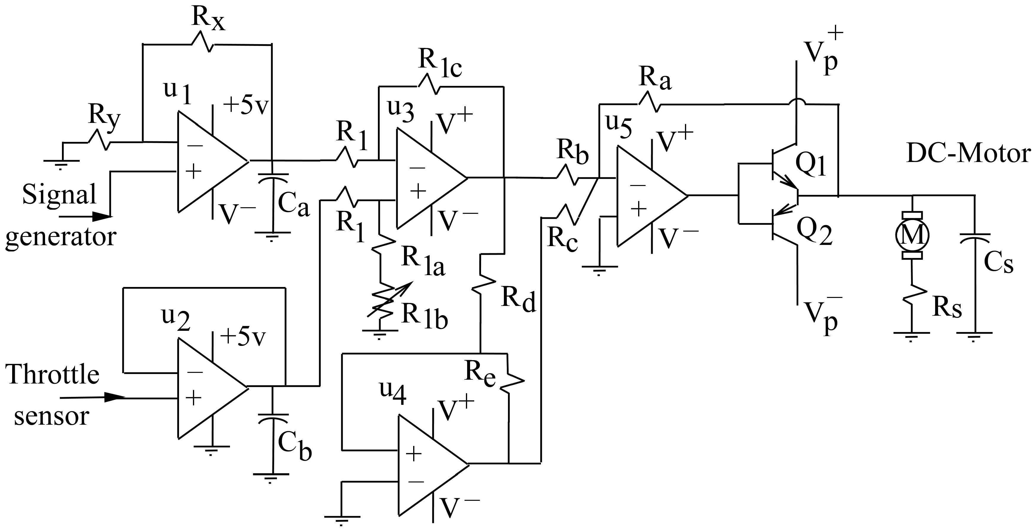
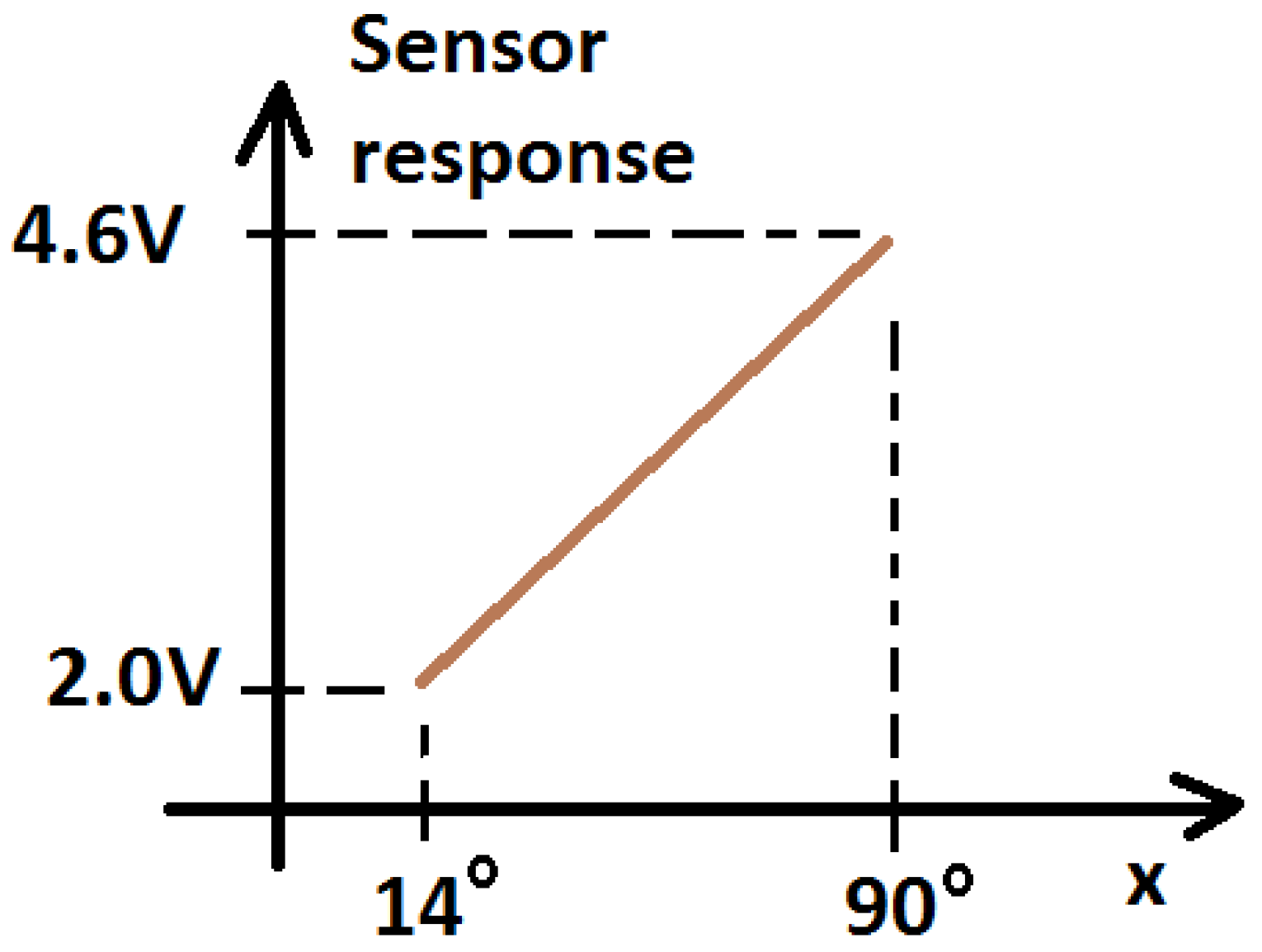
  • The difference block that produces the error signal by reading the throttle sensor and the reference trajectory signal is implemented by the operational amplifier u 3 . The potentiometer in this block is employed to compensate mismatch among the resistance values. Therefore, u 2 is conceived to buffer the throttle sensor information, and u 1 is a buffer and amplifier of the user reference trajectory supplied by a signal generator device. We use the signal generator block from the PicoScope 2000 Series digital Oscilloscope (PicoScope, Cambridgeshire, UK) device, and we employ it to read other voltage signals too. Hence, the output at this operational amplifier is actually the reference trajectory utilized by the controller.
  • The hysteretic block is implemented by the operational amplifier u 4 . Its functionality and description can be found, for example, in [27].
  • The operational amplifier u 5 is armed to collect the proportional and the hysteretical terms to produce the control signal at the output of this operational amplifier.
  • The power amplifier stage to send the control signal to the throttle DC-Motor is coined by the power amplifiers Q 1 and Q 2 .
On the other hand, Figure 4 shows a photo of the experimental platform. Figure 5 gives the technical information given by the throttle sensor according to the throttle-plate angular position. This is the only sensor employed by the controller. Because it is actually an angular potentiometer to measure the rotary displacement of the throttle device, this potentiometer would be made of carbon, plastic, or ceramic metal. As a result, its resolution is high. Unluckily, no additional technical data are freely available. Figure 6, Figure 7, Figure 8, Figure 9, Figure 10 and Figure 11 describe the experimental outcomes. In addition to the annotations given in each figure label, from Figure 8, it can be estimated that there is a settling-time of 0.03 s to a unit step-response (in the cited experiment results, the input step-size is about 2 s), and that it shows a kind of under-actuated dynamic.
During the experimenting and electronic design stages, we observe the following important facts:
  • The capacitor C S is connected in parallel to the throttle DC-Motor, which is important not just to mitigate radiation of electromagnetic perturbation waves, but also to reduce other noises in the closed-loop system because of the commutation actions produced by the hysteretical block.
  • The capacitors C a and C b are not critical. These can be any values, for instance, between 0.01 μF to 10 μF. These capacitors are used to filter noisy signals.
  • The power resistance R S is added as an option to measure the current demanded by the throttle DC-Motor. This was implemented for future works where this information may be important depending on the future application.
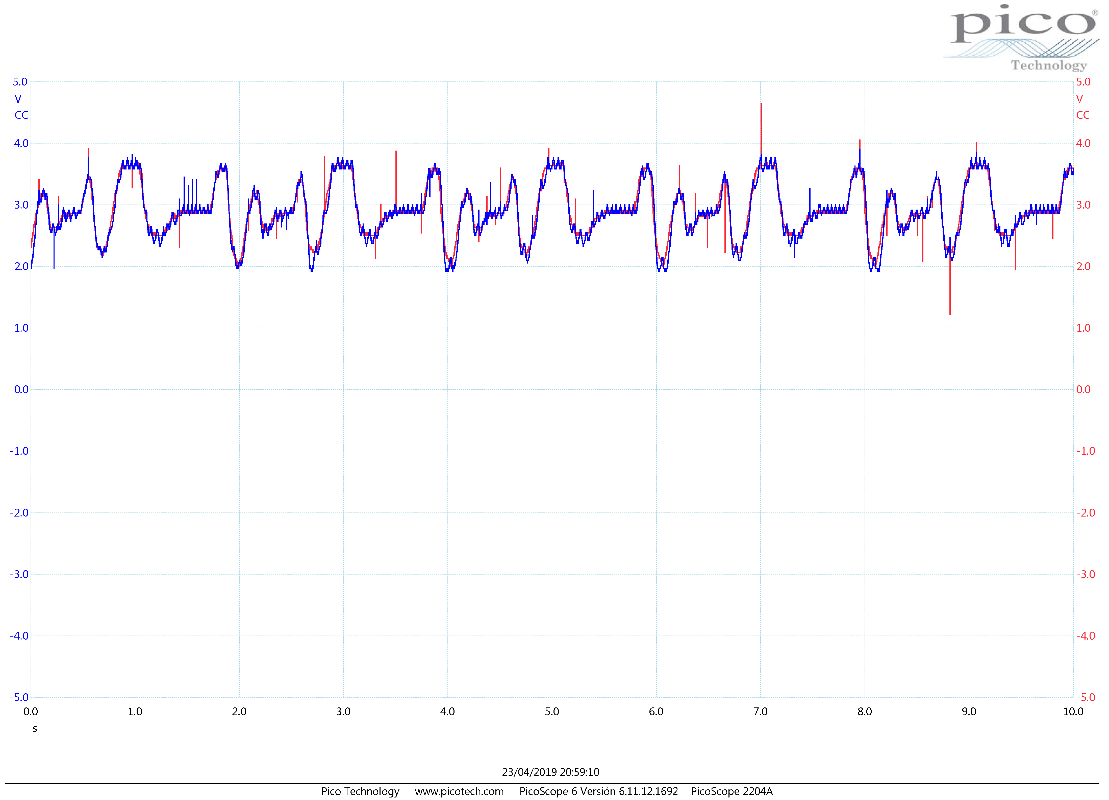
  • From the experimental result pictures, we can observe some “spikes” that may be eliminated by using appropriate filters and well tuned choke inductors. We decide to keep them, however, in order to validate the robustness controller performance under sensor noise perturbation too.
  • The controller approach is more simple than a PID controller, for instance.
On the other hand, other pitch systems may be emulated by the throttle device, for instance, the propeller pitch drives a compass thruster of floating units [28,29]. Finally, future works include:
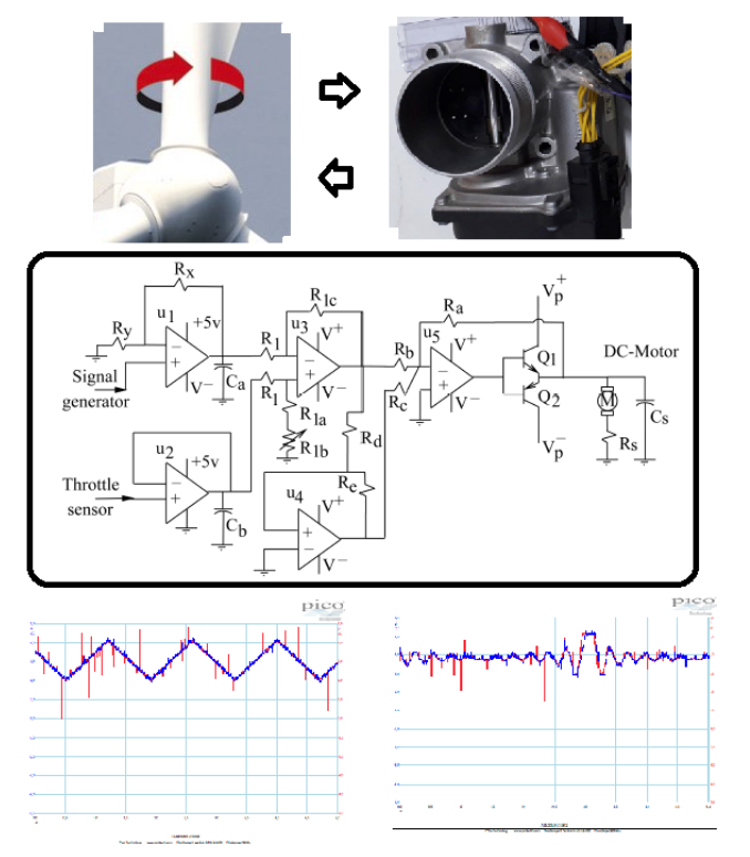
  • To develop a Hardware-In-the-Loop system where a wind turbine is simulated in a computer and the pitch actuator dynamic is captured by a throttle device.
  • To realize a fault detection algorithm applied to wind turbine pitch systems. Then, to use the proposed platform for its performance validation.
  • To compare other controller strategies with respect to the given controller approach.
To close this section, the advantages and disadvantages are annotated as follows. The main advantages include a robust and simple controller architecture. Hence, few electronic components are needed for its realization and it results are inexpensive. On the other hand, its main disadvantage is the zigzag dynamic produced by the controller around the profile reference command.

4. Conclusions

In this paper an analog electronic design of a proportional and a hysteretic term controller was developed and validated experimentally. The controller was conceived to manipulate a throttle device that may emulate a pitch control of a wind turbine. Hence, in this kind of application, the controller performance requirements were not the same. Moreover, in the given experiments, the throttle plate movement was wide, formalizing the well deployment of the proposed control law. Thus, overall, the controller approach results were simple and easy to implement by employing operational amplifiers. In addition, the designed experimental platform, including the Pico-Scope device and the throttle device, cost under 500 Euros. Finally, and in comparison to other controllers applied to this mechanical device, the stated approach is too simple. Other control techniques were based on computation, such as Fuzzy Logic and Neuronal networks, and the control algorithm results complex, requiring fast digital processors and strong computation instructions. These other techniques are also based on a non-linear model of the throttle system, making it difficult to arrive at the controller outcomes and stability proof. Hence, the submitted approach is easy to understand. Additionally, and according to the literature review stated in the introduction section, the development of inexpensive and simple analog circuits to control blade rotational systems appears to be a crucial and challenging task. Finally, from the experimental point of view, the controller has a settling-time of about 0.03 s to a unit step-response. This number is acceptable in the blade system manipulation of wind turbines.

Funding

This research was completely funded by the Spanish Ministry of Economy and Competitiveness/Fondos Europeos de Desarrollo Regional (MINECO/FEDER) grant number DPI2015-64170-R.

Conflicts of Interest

The author declares no conflict of interest. The founding sponsors had no role in the design of the study; in the collection, analyses, or interpretation of data; in the writing of the manuscript, and in the decision to publish the results.

Abbreviations

The following abbreviations are used in this manuscript:
DC-MotorDirect-Current motor
PID controllerProportional-Integral-Derivative controller
VDOVereinigte DEUTA - OTA (English: United DEUTA - OTA)
s g n signum
P.N.Part Number
MMotor

References

  1. Vidal Seguí, Y.; Acho Zuppa, L.; Pozo Montero, F. Robust control of an electronic throttle system via switched chattering control: Benchmark experiments. In Proceedings of the IFAC Workshop on Engine and Powertrain Control, Simulation and Modeling, Rueil, France, 30 November–2 December 2009. [Google Scholar]
  2. Vidal, Y.; Acho, L.; Luo, N.; Tutiven, C. Hardware in the loop wind turbine simulator for control system testing. In Wind Turbine Control and Monitoring; Springer: Berlin, Germany, 2014; pp. 449–466. [Google Scholar]
  3. Vidal, Y.; Acho, L.; Luo, N.; Zapateiro, M.; Pozo, F. Power control design for variable-speed wind turbines. Energies 2012, 5, 3033–3050. [Google Scholar] [CrossRef]
  4. Deur, J.; Pavkovic, D.; Peric, N.; Jansz, M.; Hrovat, D. An electronic throttle control strategy including compensation of friction and limp-home effects. IEEE Trans. Ind. Appl. 2004, 40, 821–834. [Google Scholar] [CrossRef]
  5. Pavković, D.; Deur, J.; Jansz, M.; Perić, N. Adaptive control of automotive electronic throttle. Control Eng. Pract. 2006, 14, 121–136. [Google Scholar] [CrossRef]
  6. Vargas, A.N.; Menegaz, H.M.; Ishihara, J.Y.; Acho, L. Unscented Kalman filters for estimating the position of an automotive electronic throttle valve. IEEE Trans. Veh. Technol. 2016, 65, 4627–4632. [Google Scholar] [CrossRef]
  7. Pujol, G.; Vidal, Y.; Acho, L.; Vargas, A.N. Asymmetric modelling and control of an electronic throttle. Int. J. Numer. Model. Electron. Netw. Devices Fields 2016, 29, 192–204. [Google Scholar] [CrossRef]
  8. Vargas, A.; Acho Zuppa, L.; Pujol Vázquez, G.; Oliveira, R.C.; do Val, J.B.; Peres, P.L. Robust H2 static output feedback to control an autmomotive throttle valve. In Proceedings of the 2014 American Control Conference—ACC, Portland, OR, USA, 4–6 June 2014; pp. 3141–3146. [Google Scholar]
  9. Vargas, A.N.; Acho, L.; Pujol, G.; Costa, E.F.; Ishihara, J.Y.; do Val, J.B. Output feedback of Markov jump linear systems with no mode observation: An automotive throttle application. Int. J. Robust Nonlinear Control 2016, 26, 1980–1993. [Google Scholar] [CrossRef]
  10. Zaki, A.M.; El-Bardini, M.; Soliman, F.; Sharaf, M.M. Embedded two level direct adaptive fuzzy controller for DC motor speed control. Ain Shams Eng. J. 2018, 9, 65–75. [Google Scholar] [CrossRef] [Green Version]
  11. Zapateiro De la Hoz, M.; Acho, L.; Vidal, Y. An experimental realization of a chaos-based secure communication using arduino microcontrollers. Sci. World J. 2015, 2015, 123080. [Google Scholar] [CrossRef] [PubMed]
  12. Acho, L. A discrete-time chaotic oscillator based on the logistic map: A secure communication scheme and a simple experiment using Arduino. J. Frankl. Inst. 2015, 352, 3113–3121. [Google Scholar] [CrossRef] [Green Version]
  13. Barber, R.; Horra, M.; Crespo, J. Control practices using simulink with arduino as low cost hardware. IFAC Proc. Vol. 2013, 46, 250–255. [Google Scholar] [CrossRef]
  14. Gambier, A.; Behera, A. Integrated Pitch Control System Design of a Wind Turbine by Using Multiobjective Optimization. IFAC-PapersOnLine 2018, 51, 239–244. [Google Scholar] [CrossRef]
  15. Yuan, Y.; Tang, J. Adaptive pitch control of wind turbine for load mitigation under structural uncertainties. Renew. Energy 2017, 105, 483–494. [Google Scholar] [CrossRef] [Green Version]
  16. Gao, R.; Gao, Z. Pitch control for wind turbine systems using optimization, estimation and compensation. Renew. Energy 2016, 91, 501–515. [Google Scholar] [CrossRef]
  17. Hatami, A.; Moetakef-Imani, B. Innovative adaptive pitch control for small wind turbine fatigue load reduction. Mechatronics 2016, 40, 137–145. [Google Scholar] [CrossRef]
  18. Oueslati, M.; Dahmouni, A.; Nasrallah, S.B. Effects of sudden change in pitch angle on oscillating wind turbine airfoil performances. Eng. Anal. Bound. Elem. 2017, 81, 21–34. [Google Scholar] [CrossRef]
  19. Rezaeiha, A.; Kalkman, I.; Blocken, B. Effect of pitch angle on power performance and aerodynamics of a vertical axis wind turbine. Appl. Energy 2017, 197, 132–150. [Google Scholar] [CrossRef] [Green Version]
  20. Jiao, X.; Li, G.; Wang, H. Adaptive finite time servo control for automotive electronic throttle with experimental analysis. Mechatronics 2018, 53, 192–201. [Google Scholar] [CrossRef]
  21. Chaaban, R.; Ginsberg, D.; Fritzen, C.P. Structural load analysis of floating wind turbines under blade pitch system faults. In Wind Turbine Control and Monitoring; Springer: Berlin, Germany, 2014; pp. 301–334. [Google Scholar]
  22. Dimeas, I.; Petras, I.; Psychalinos, C. New analog implementation technique for fractional-order controller: A DC motor control. AEU-Int. J. Electron. Commun. 2017, 78, 192–200. [Google Scholar] [CrossRef]
  23. Grochowski, E.T.; Sharma, V.; Matthews, G.S.; Joshi, V.; Kling, R.M. Microprocessor with Digital Power Throttle. U.S. Patent 6,564,328, 13 May 2003. [Google Scholar]
  24. Krieder, R.D. Automatic Speed Control for Heavy Vehicles. U.S. Patent 4,419,729, 6 December 1983. [Google Scholar]
  25. Guerra, R.; Acho, L.; Aguilar, L. Adaptive friction compensation for mechanisms: A new perspective. Int. J. Robot. Autom. 2007, 22, 155–159. [Google Scholar] [CrossRef]
  26. Guerra, R.; Acho, L. Adaptive friction compensation for tracking control of mechanisms. Asian J. Control 2007, 9, 422–425. [Google Scholar] [CrossRef]
  27. Franco, S. Design with Operational Amplifiers and Analog Integrated Circuits; McGraw-Hill: New York, NY, USA, 2002; Volume 1988. [Google Scholar]
  28. Chybowski, L. Azimuth Thruster Hydraulic Instalations Reliability Model. In Proceedings of the Бaлттехмаш 2006, Kaliningrad, Russia, 20–23 June 2006; pp. 103–109. [Google Scholar]
  29. Chybowski, L.; Matuszak, Z. A Particular Model of Redundancy Useful in the Assessment of Operational Reliability and Safety of a Dynamic Positioning System of an Offshore Vessel. Pol. J. Environ. Stud. 2006, 15, 27–34. [Google Scholar]
Figure 1. A general schematic representation of a throttle device. The shown throttle body is manufactured by Continental Siemens VDO, Model A2C59511705, P.N. 06F133062J and employed by many vehicles [6]. In addition, x = x ( t ) and u = u ( t ) are the throttle plate angular position and the control input, respectively.
Energies 12 01961 g001
Figure 2. Hysteretic behaviour. Essentially, hysteresis has different outcomes dependent on the direction of the input signal. In addition, this behaviour has memory due to the fact that the output at any instance of time may depend on the whole history of the input signal.
Energies 12 01961 g002
Figure 3. Circuit realization of the stated controller approach. The parameters used are: R y = 1.5 k Ω , R x = 4.6 k Ω , R 1 = 10 k Ω , R 1 c = 20 k Ω , R 1 a = 8.2 k Ω , R 1 b = 10 k Ω (potentiometer), R d = 330   Ω , R e = 1 M Ω , R b = 330   Ω , R c = 220   Ω , R a = 22 k Ω , R S = 1   Ω (power resistance), C S = 10 pF, C a = 1   μ F and C b = 1   μ F . The electrical values are: V + = 15 V, V = 15 V, V p + = 18 V, and V p = 18 V. Finally, we use operational amplifiers μ A 741 , and the power transistors M J E 3055 T and M J E 2955 T , for Q 1 and Q 2 , respectively. The letter ‘M’ stands for the DC-motor of the throttle mechanism.
Energies 12 01961 g003
Figure 4. A photo of the designed experimental platform. The power transistors and the controller analog circuit, as can be observed, are easily to realize. This evidences its low cost implementation too.
Energies 12 01961 g004
Figure 5. Sensor output versus throttle-plate angular position. When the throttle plate is completely open ( x = 90 degrees) the sensor output voltage is 4.6 V, and when the throttle-plate is closed (at x = 14 degrees), the related output is 2.0 V.
Energies 12 01961 g005
Figure 6. Experimental results. The blue line is the measured throttle angular position and the red line is the programmed reference. From these results, it is observed that the throttle-plate angular position follows the desired trajectory by performing a zig-zag displacement around it. Hence, the tracking error is bounded and it may depend on the size of the hysteretic-loop controller term.
Energies 12 01961 g006
Figure 7. Experimental outcomes. The blue line is the measured throttle angular position and the red line is the programmed reference trajectory. This kind of desired tracking signal measures the ability of the controller to follow a sinusoidal reference typically employed in some mechanical harmonic motions.
Energies 12 01961 g007
Figure 8. Experimental answers. The blue line is the measured throttle angular position and the red line is the programmed desired trajectory. Here, the given reference statement is a square representation. The main objective of this reference profile is to evaluate the settling-time of the controller under step-variation of the reference command. In the wind turbines application, this settling-time is not required to be fast.
Energies 12 01961 g008
Figure 9. Experimental plots. The blue line is the measured throttle angular position and the red line is the desired reference route. In this case, the used reference corresponds to a class of a sinc function typically presented in signal processing by using the Fourier transform.
Energies 12 01961 g009
Figure 10. Experimental measurements. The blue line is the measured throttle angular position and the red line is the desired throttle motion. In this experiment, we set this reference instruction in order to capture the controller ability to track a cutted reference trajectory.
Energies 12 01961 g010
Figure 11. Experimental measurements. The blue line is the measured throttle angular position and the red line is the desired throttle motion. By using a class of random reference programming, the ability of the controller to lead this kind of time-varying signal is notably appreciated.
Energies 12 01961 g011

