A Modified Wireless Power Transfer System for Medical Implants


Abstract
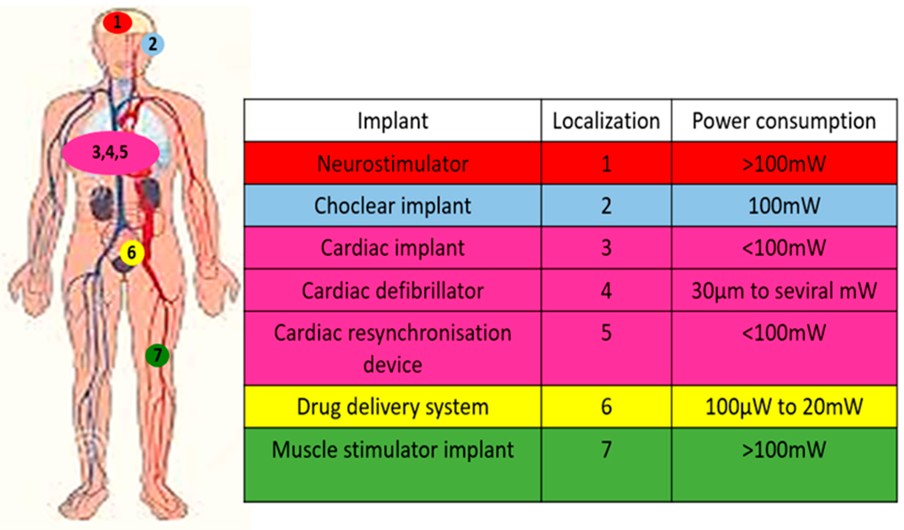
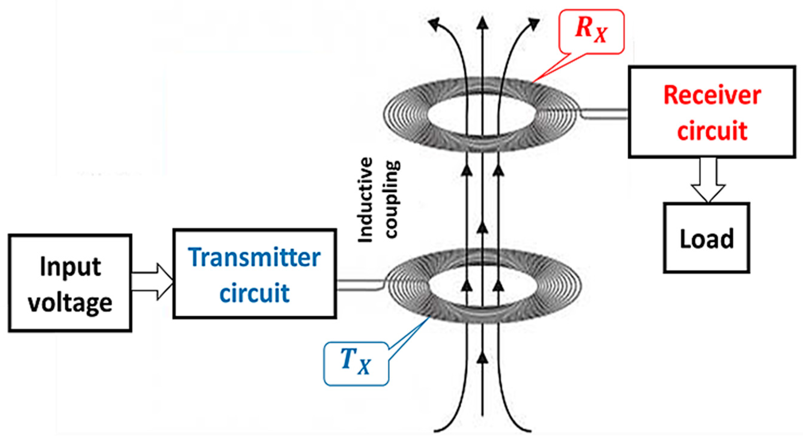
:1. Introduction
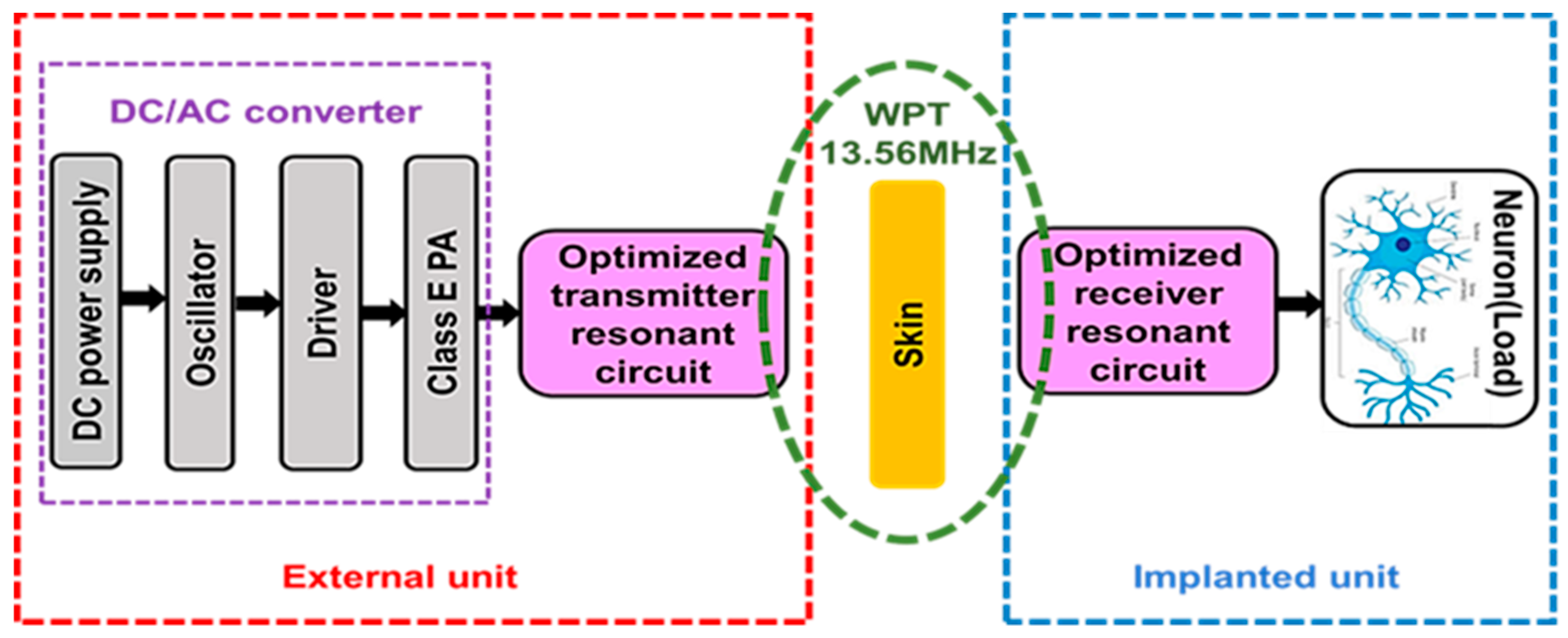
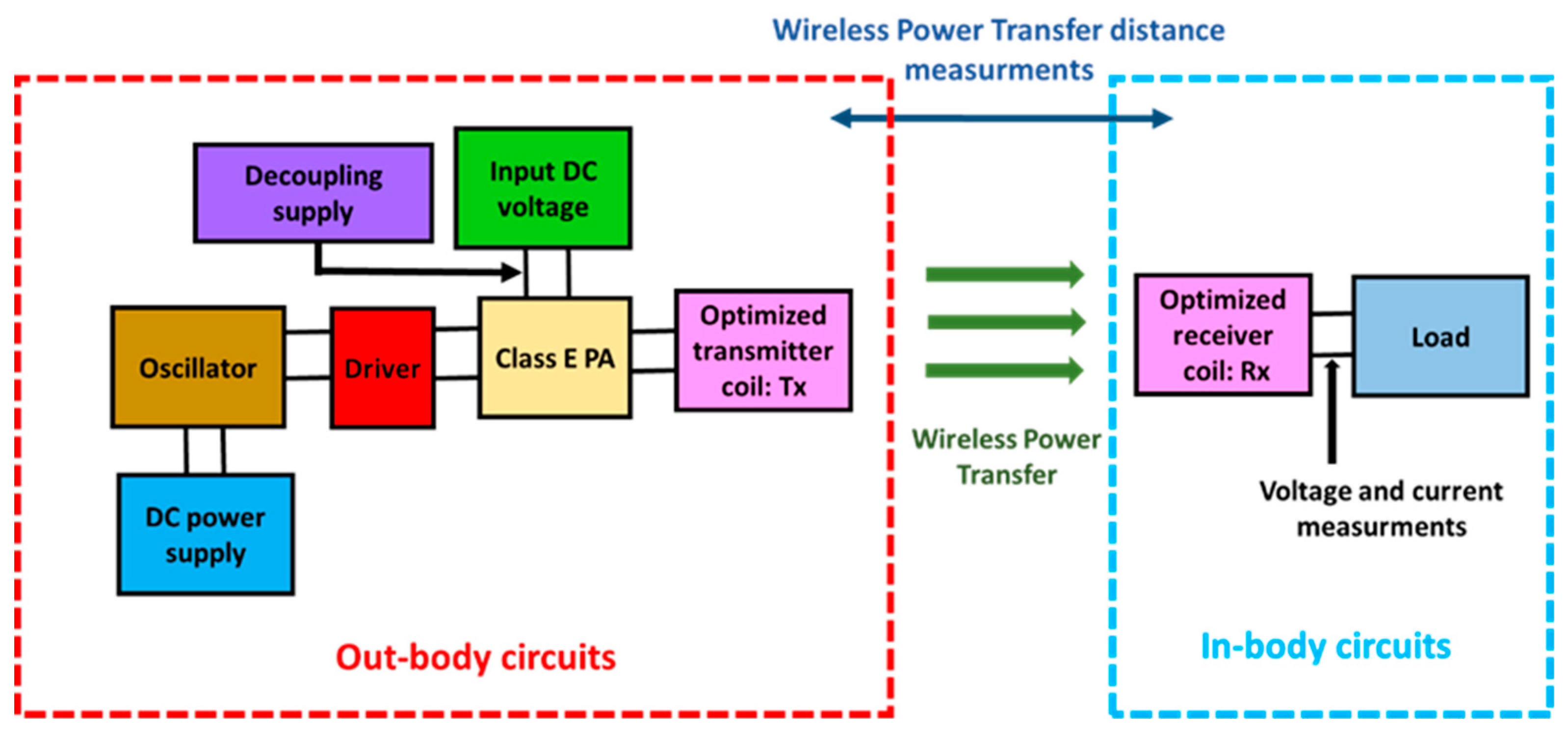
2. Design of the Proposed System
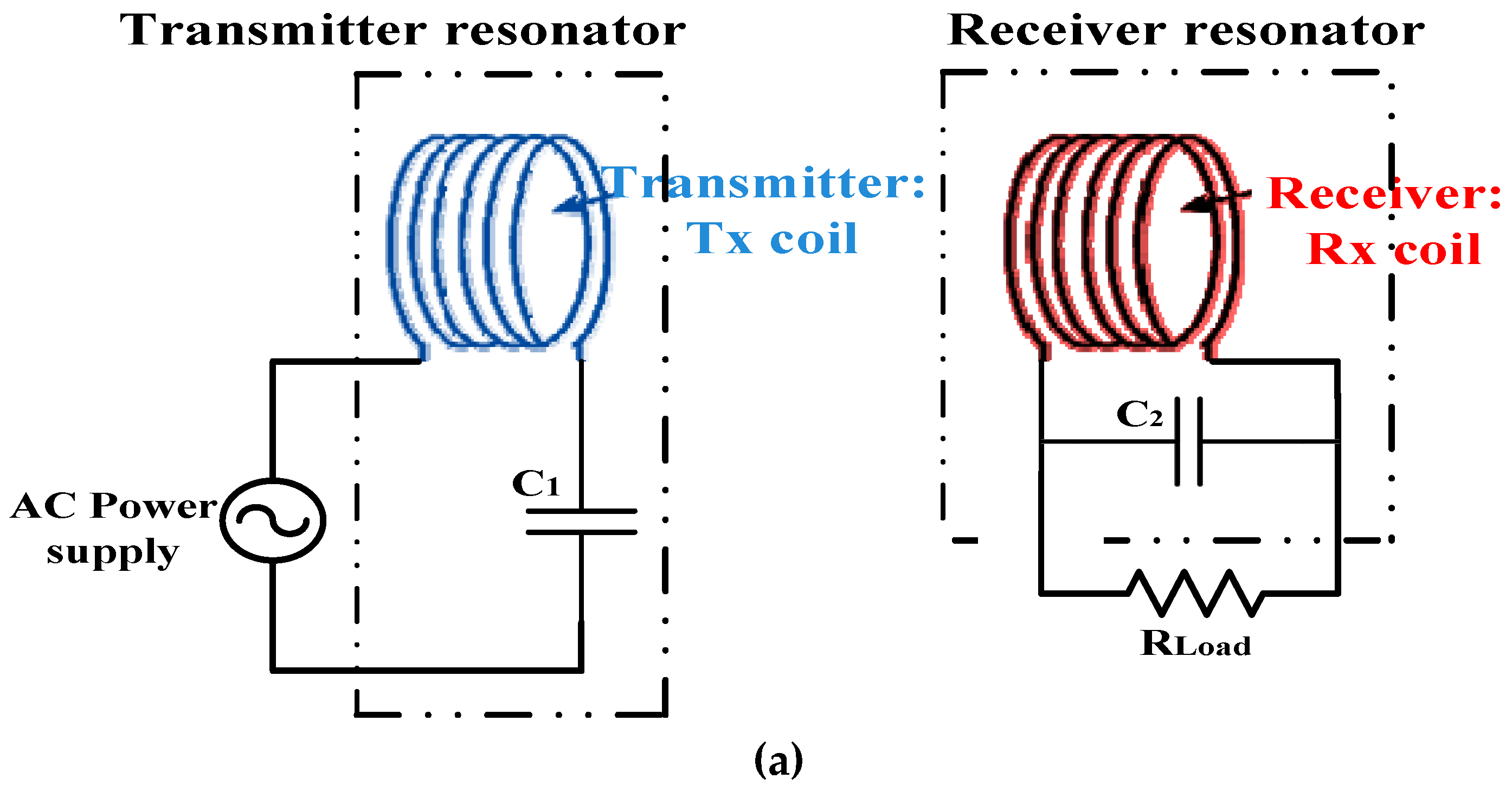
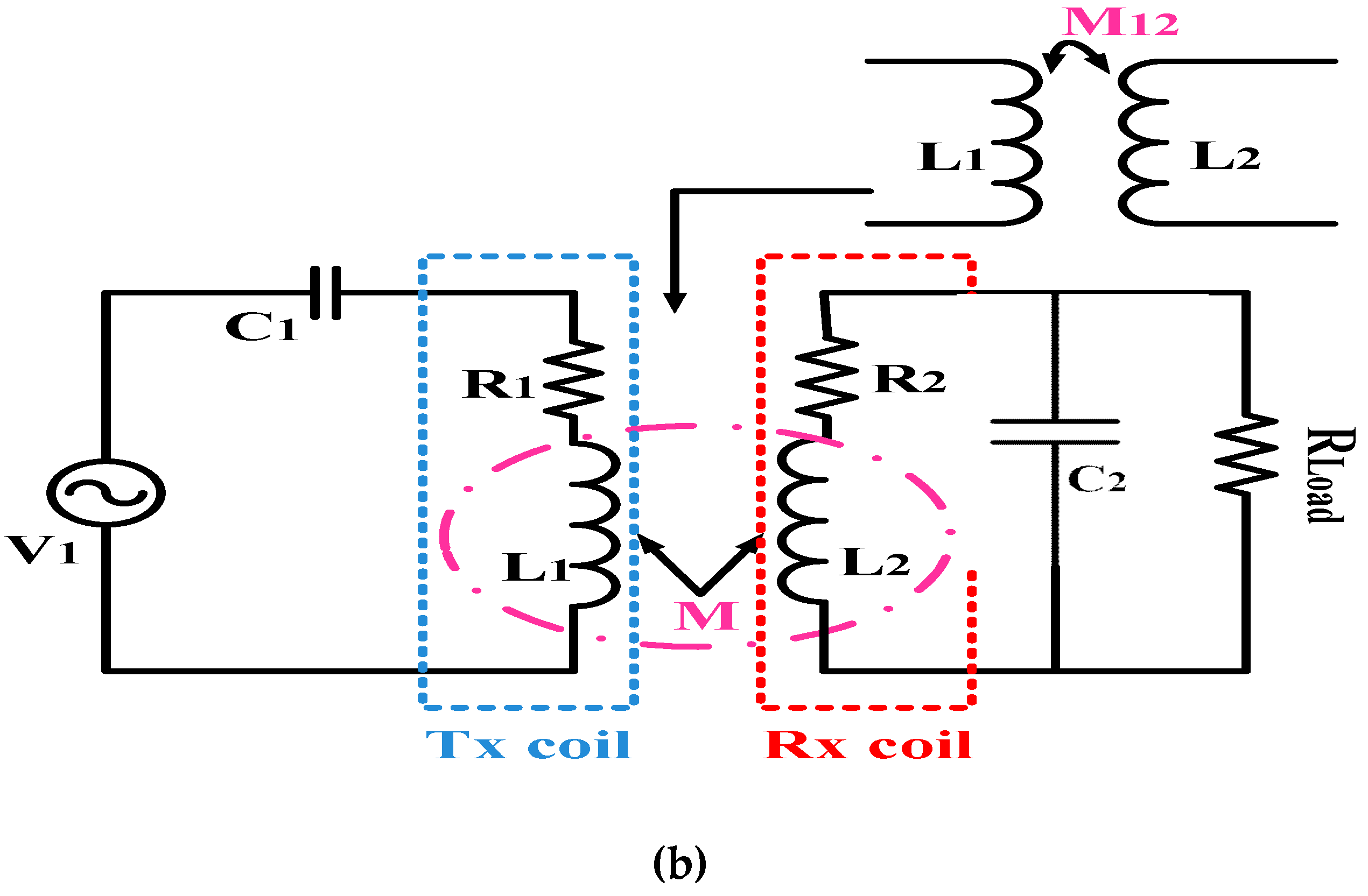
2.1. Equivalent Electrical Circuit of the Proposed RIC WPT System
- (1)
- (2)
- (3)
- In the case where a rectifier will be added to the proposed system, the parallel topology is the most adequate. As the authors in the review paper [31] have explained, the resonance at the receiver circuit can be tuned in series or in parallel. Both parallel and serial topologies deliver the same power to the implant. However, the resonant serial topology does this by using a high voltage and a low current. Since rectifiers work better at large voltages and low currents, this makes the parallel topology the leading choice in biomedical implants.
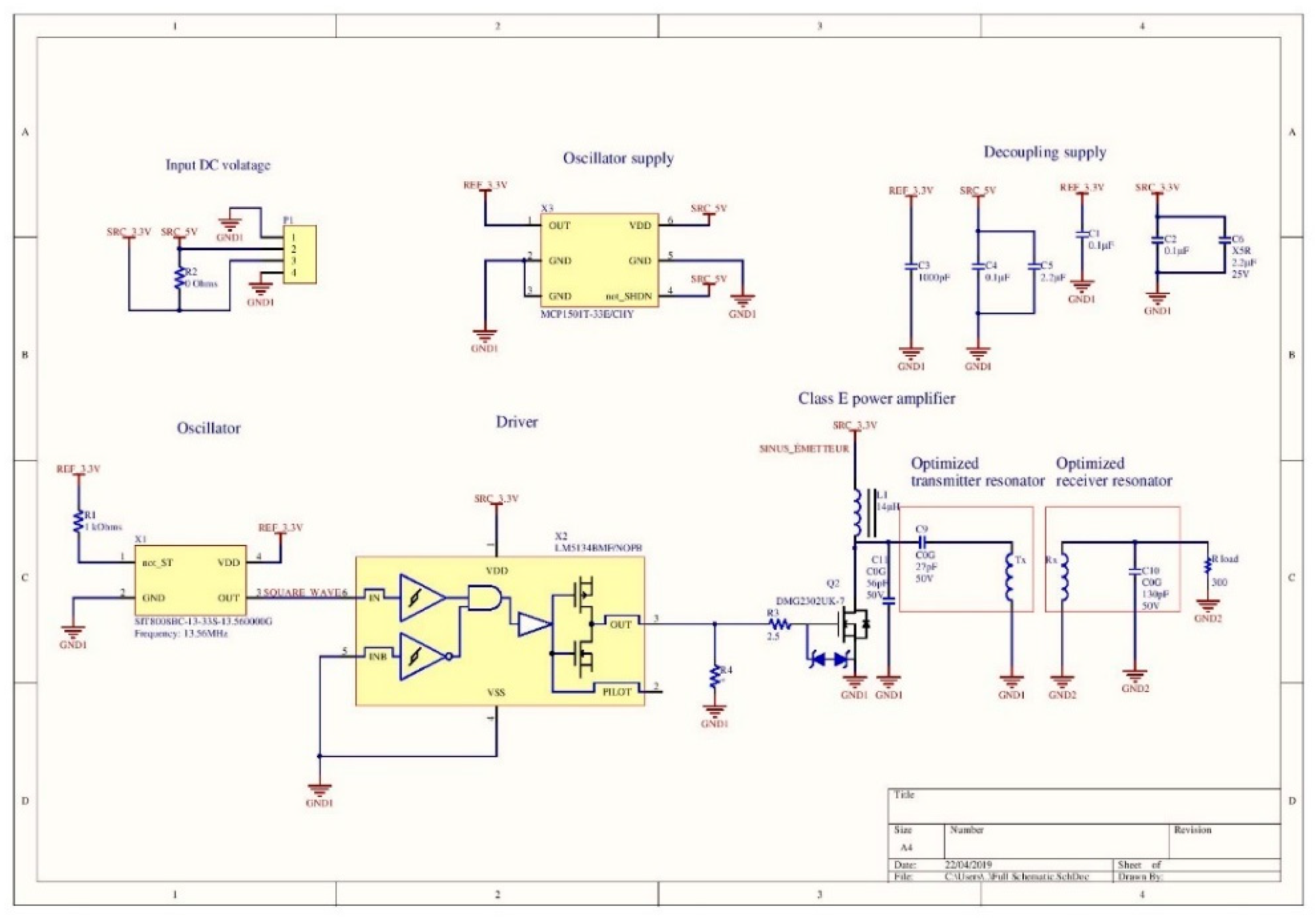
2.2. DC/AC Converter – Choices of Components and Justification
2.2.1. Oscillator SiT8008B
2.2.2. The Operating Frequency: 13.56 MHz
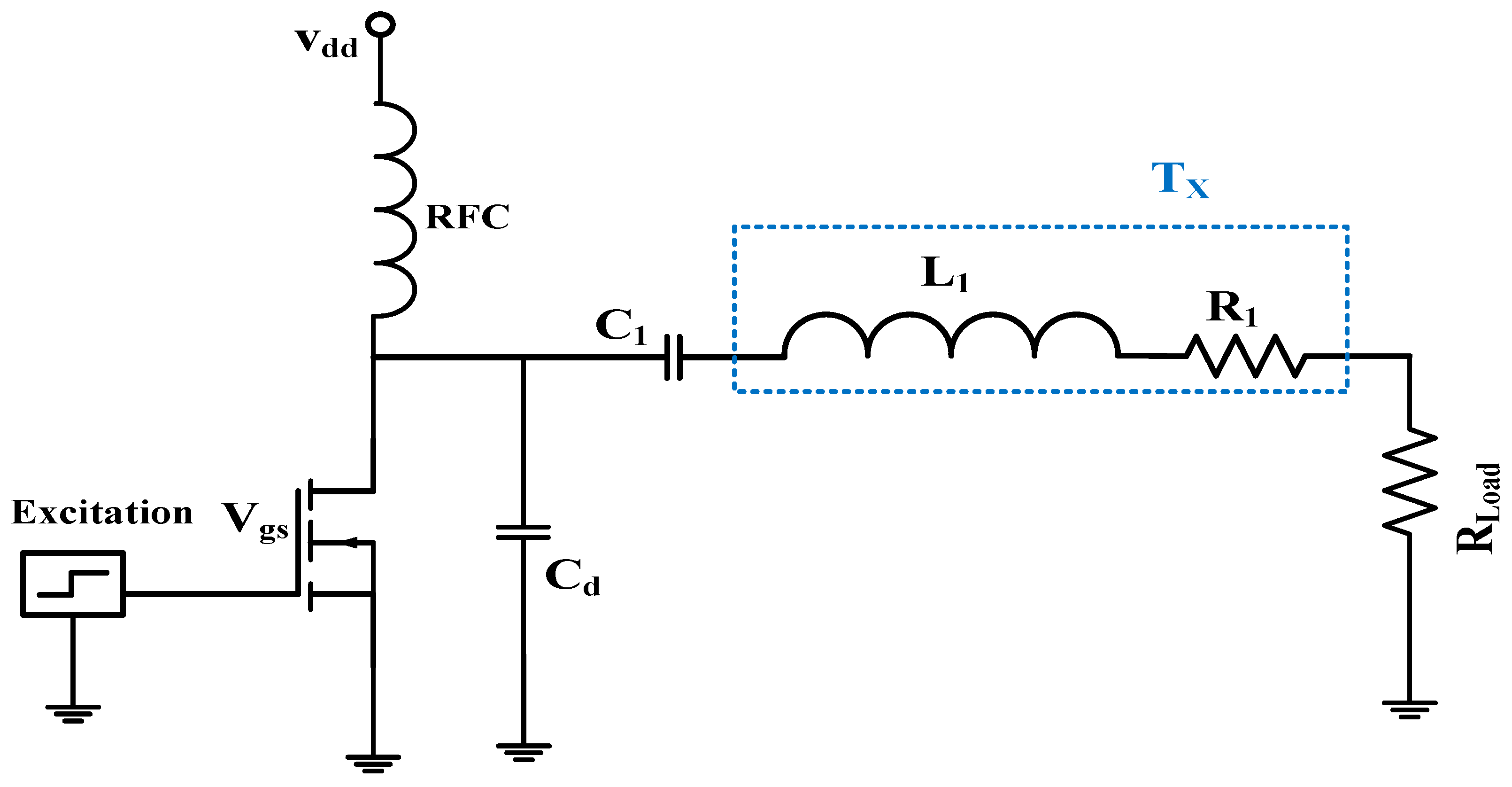
2.2.3. Class-E Power Amplifier
2.2.4. Class-E Power Amplifier Transistor DMG230UK-7
2.2.5. Driver LM5134
2.2.6. Ceramic Capacitors
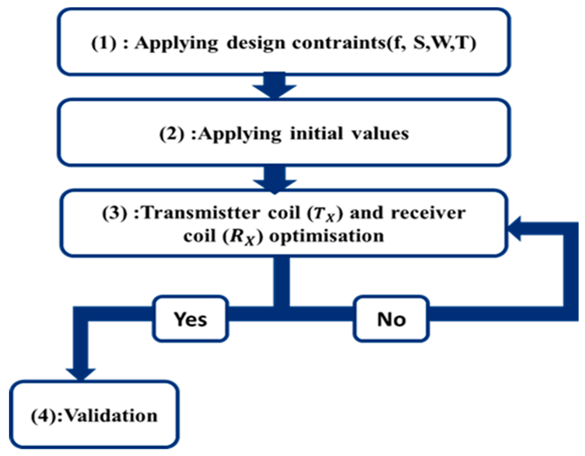
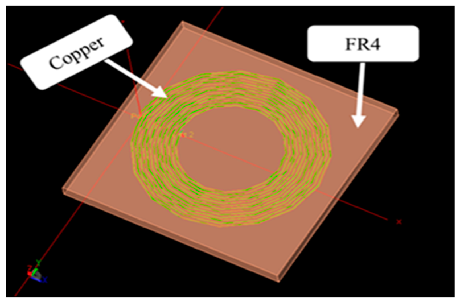
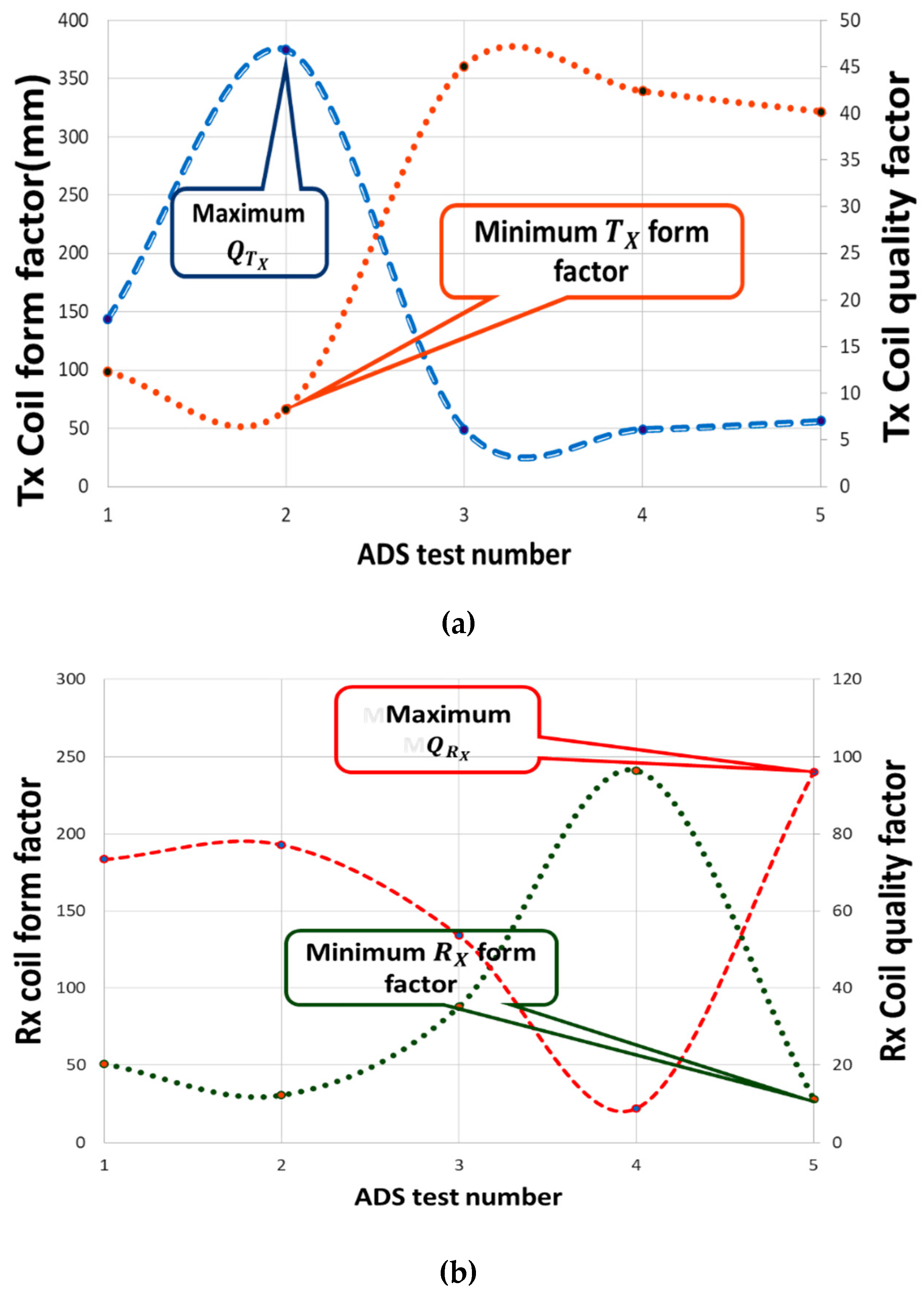
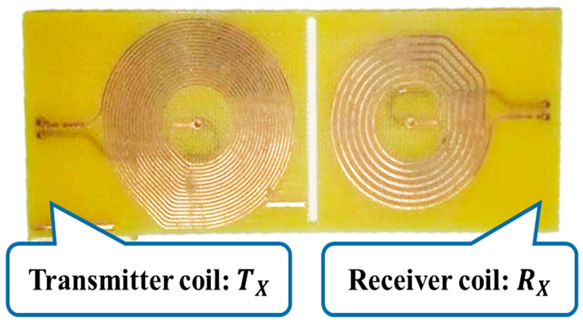
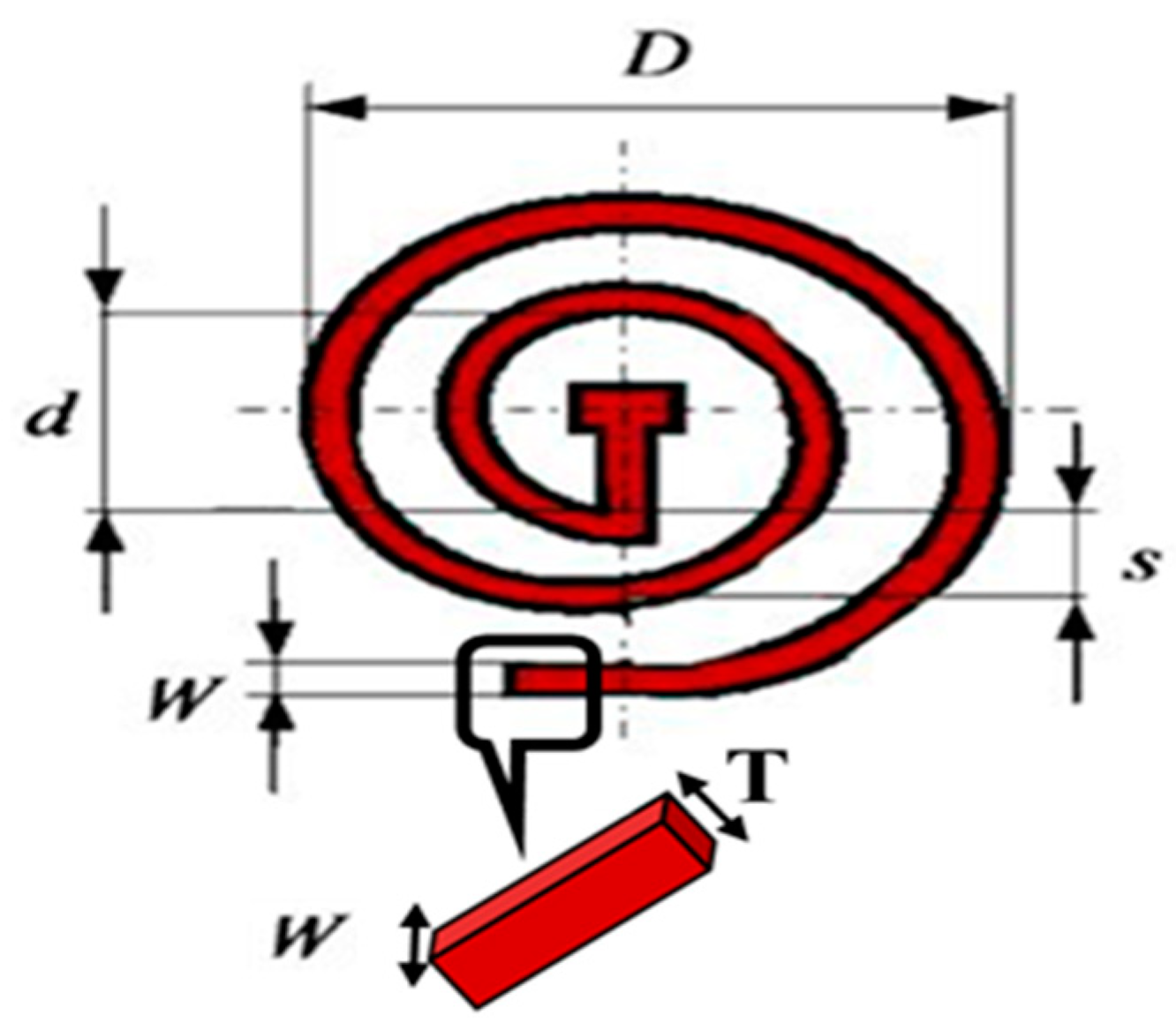
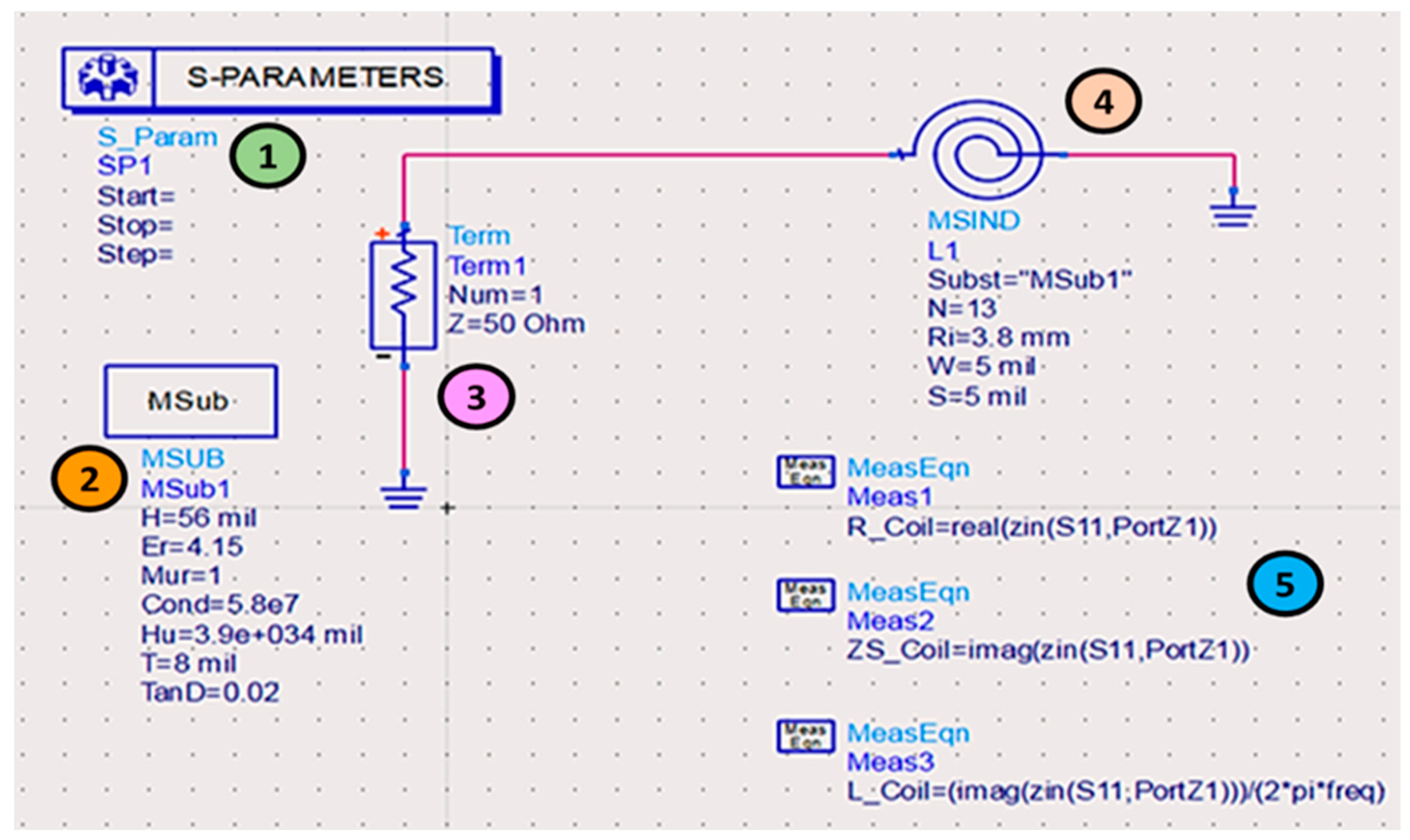
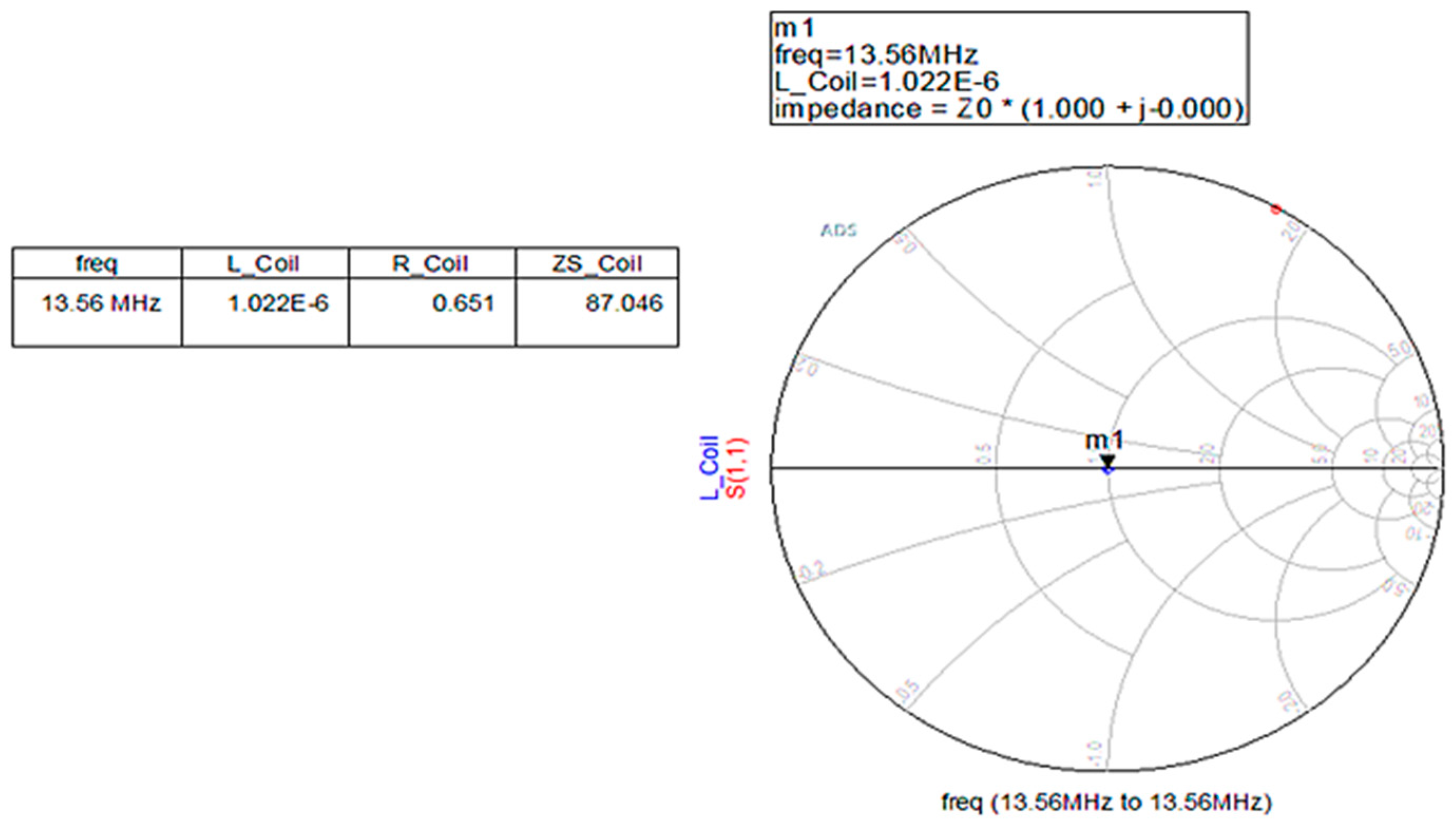
2.3. Transmitter and Receiver Coils Design Optimization
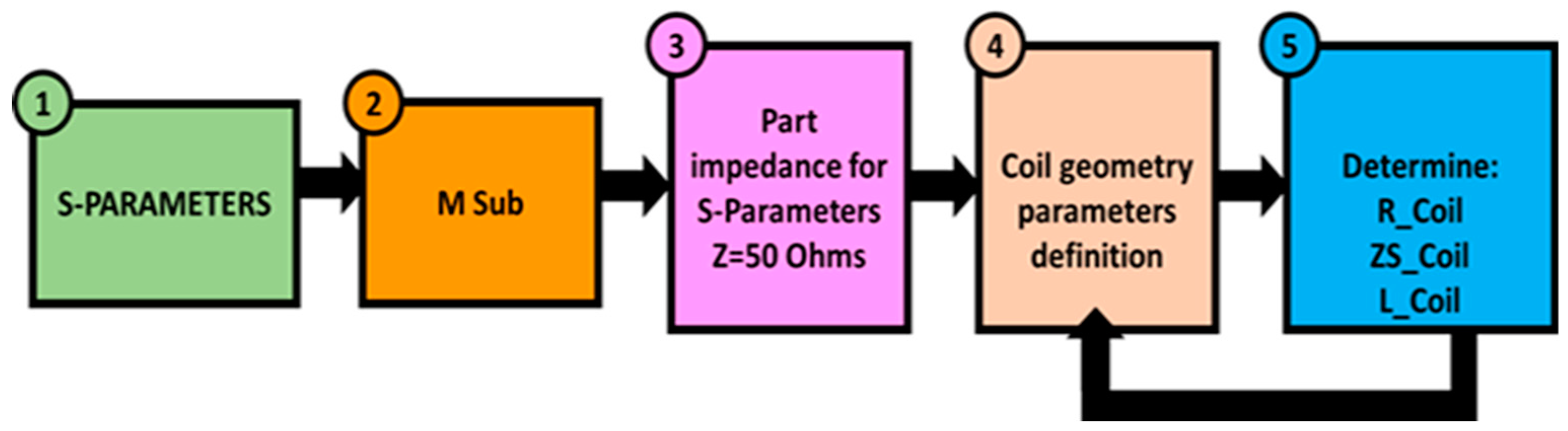
Iterative Design Procedure for the Coil Optimization
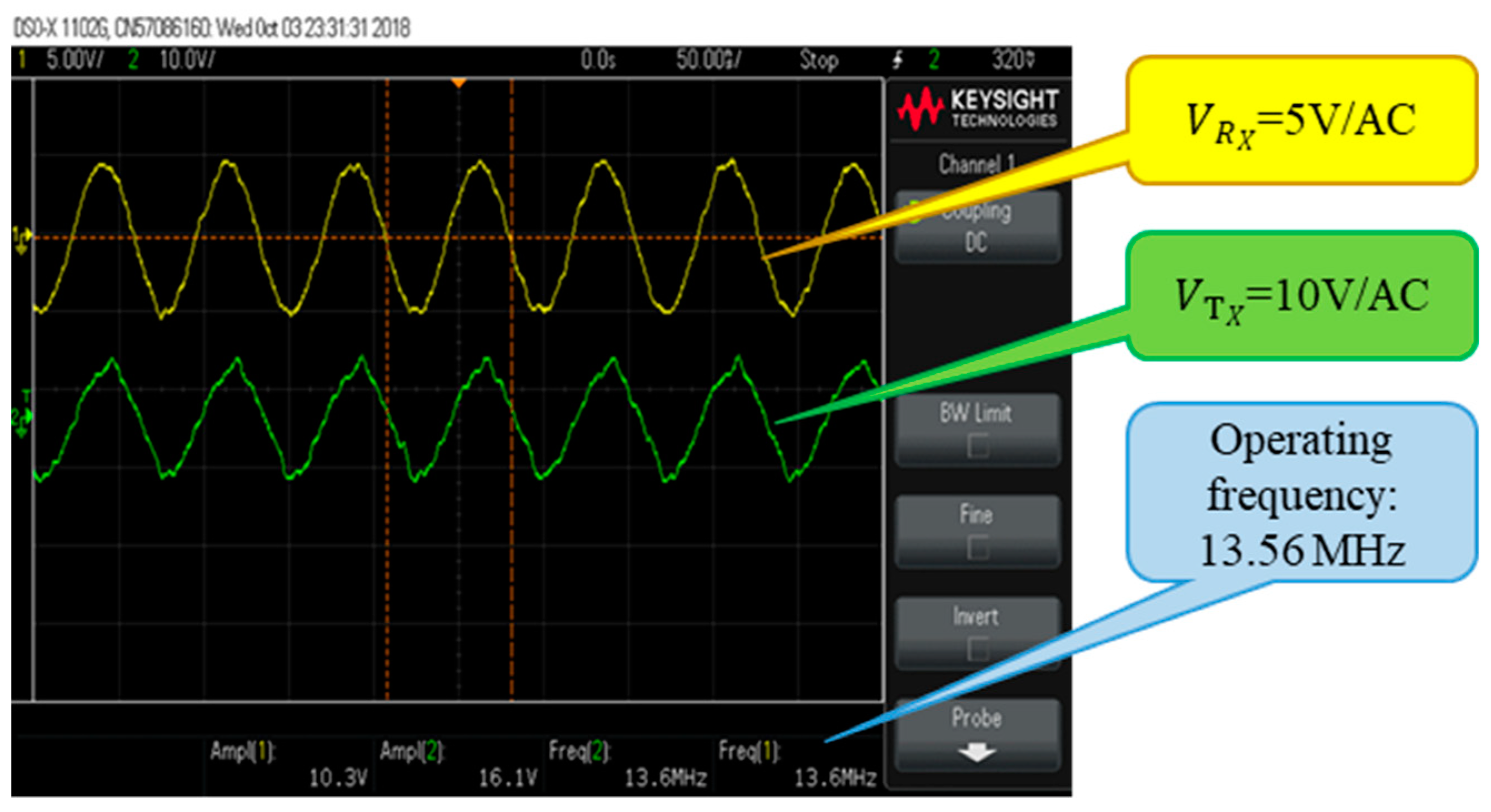
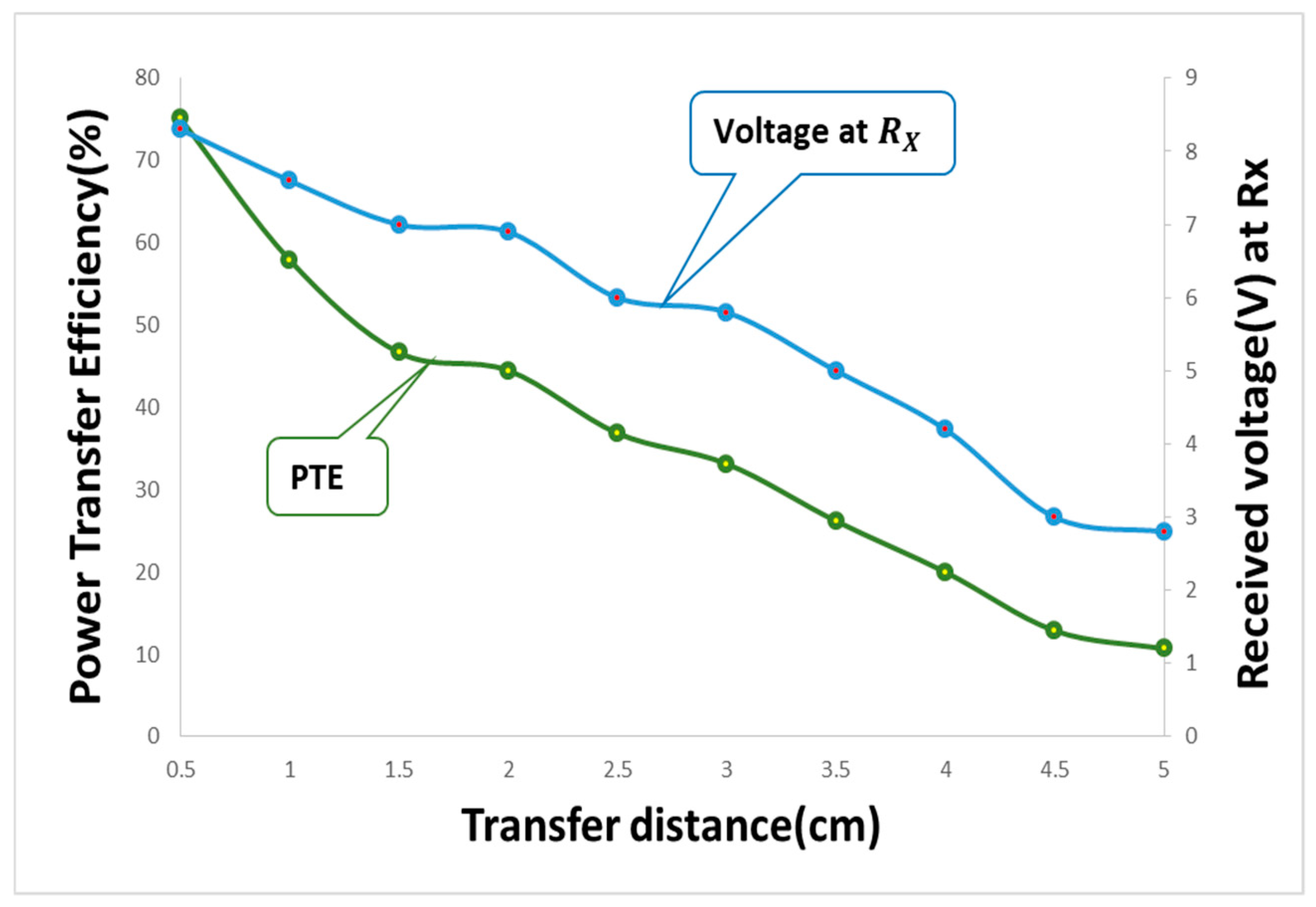
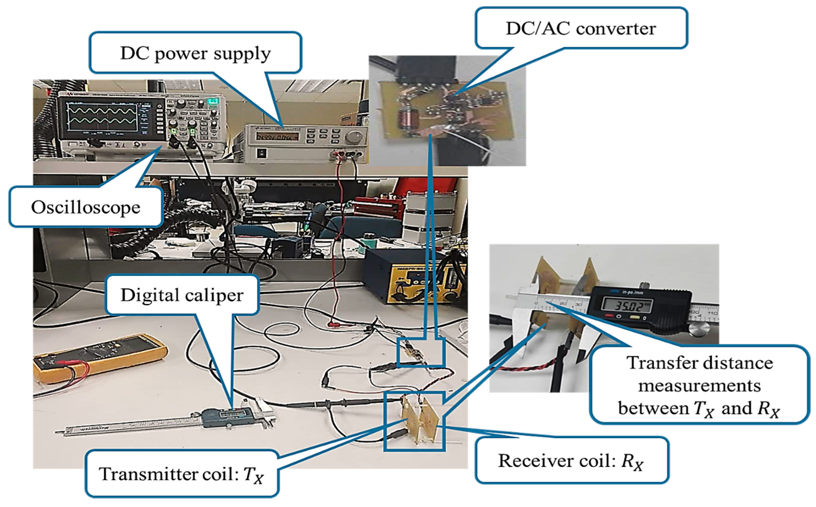
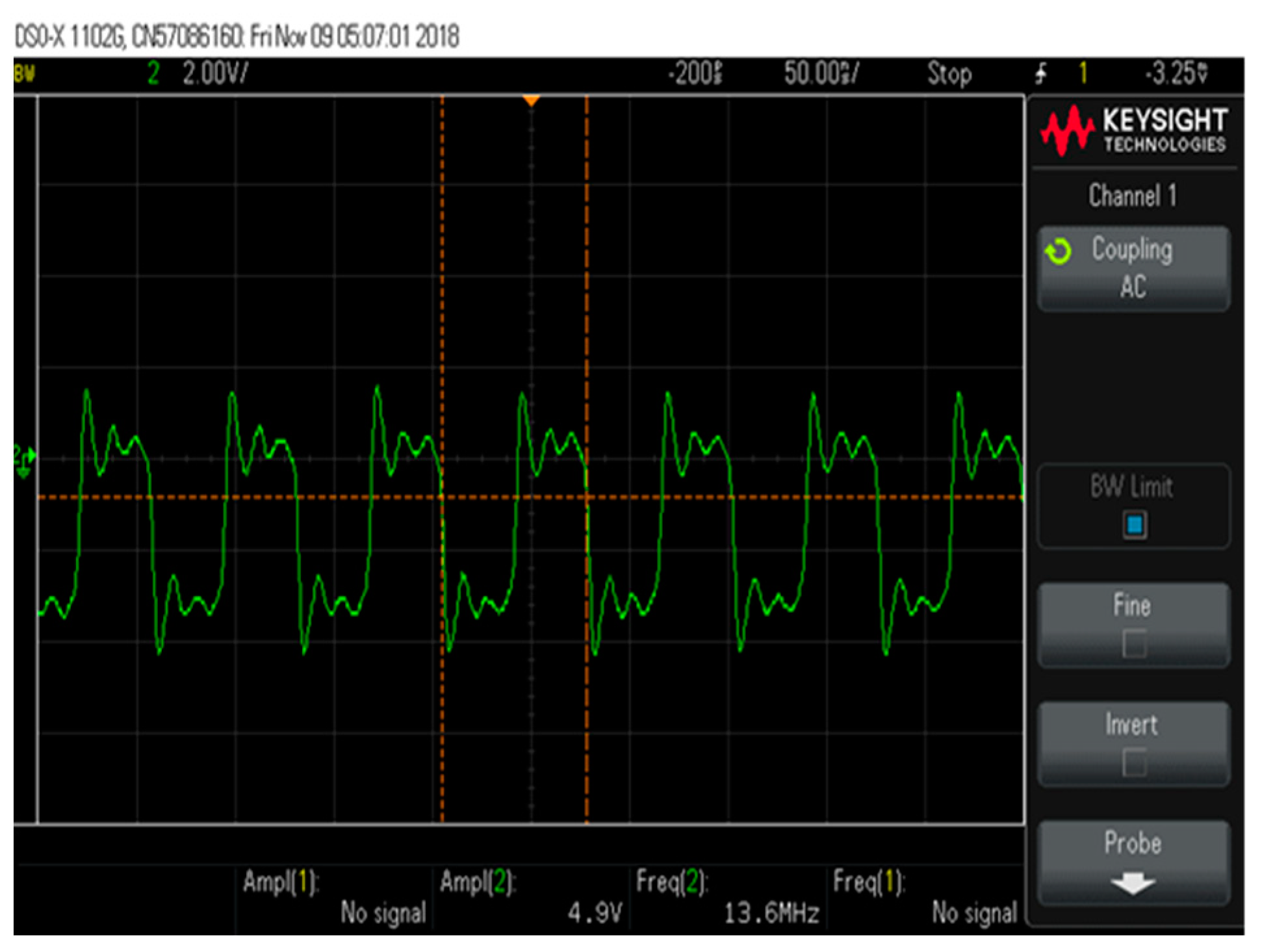
3. Testing Methodology and Experimental Results
4. Results
5. Discussion
Author Contributions
Funding
Acknowledgments
Conflicts of Interest
References
- Valentinuzzi, M. Cardiac pacemakers. IEEE Pulse, 14 July 2017; 1–4. [Google Scholar]
- Kiourti, A.; Konstantina, S.N. A review of In-body Biotelemetry Devices: Implantable, Ingestible, and Injectable. IEEE Trans. Biomed. Eng. 2017, 464, 1422–1430. [Google Scholar] [CrossRef]
- Rieger, B.; Pfau, S.; Stieglitz, J.; Asplund, T.; Ordonez, S.J. Concept and Development of an Electronic Framework Intended for Electrode and Surrounding Environment Characterization in Vivo. Sensors 2017, 17, 59. [Google Scholar] [CrossRef]
- Andreozzi, E.; Gorgiulo, D.; Fratini, G.; Esposito, A.; Bifulco, P. A Contactless Sensor for Pacemaker Pulse Detection: Design Hints and Performance Assessment. Sensors 2018, 18, 2715. [Google Scholar] [CrossRef]
- Trigui, A.; Hached, S.; Chiheb, A.; Savaria, Y.; Sawan, M. Maximizing data transmission rate for implantable devices over a single inductive link: Methodological review. IEEE Rev. Biomed. Eng. 2018, 12, 72–87. [Google Scholar] [CrossRef]
- Khokle, P.; Essello, K.; Bokor, D. Design, Modeling, and Evaluation of the Eddy Current Sensor Deeply Implanted in the Human Body. Sensors 2018, 18, 3888. [Google Scholar] [CrossRef]
- Amor, A.B.; Kouki, A.B.; Coo, H. Power approaches for implantable Medical devices. Sensors 2015, 15, 28804–28890. [Google Scholar] [CrossRef] [PubMed]
- Ben Fadhel, Y.; Ktata, S.; Rahmani, S.; Al-Haddad, K. General Principle of Wireless Power Transmission and Its Applications in Medical Devices; EICON: Florence, Italy, 2016; pp. 3–5. [Google Scholar]
- Mohamad, J.A.; Nordin, R.; Kamel Ghaghan, S.; Mahmoud Jawad, H.; Ismail, M. Opportunities and challenges for Near-Field wireless transfer: A review. Energies 2017, 10, 1022. [Google Scholar]
- Jow, U.-M.; Ghovanloo, M. Design and optimization of printed spiral coils for efficient transcutaneous inductive power transmission. IEEE Trans. Biomed. Circuits Syst. 2007, 1, 193–202. [Google Scholar] [CrossRef] [PubMed]
- Poon, S.Y.; O’Driscoll, S.; Meng, H.T. Optimal frequency for wireless power transmission into dispersive tissue. IEEE Trans. Antennas Propag. 2010, 58, 1739–1750. [Google Scholar] [CrossRef]
- Ram Rakhyani, A.K.; Mirabbasi, S.; Chiao, M. Design and optimization of resonance-based efficient wireless power delivery systems for biomedical implants. IEEE Trans. Biomed. Circuits Syst. 2011, 5, 48–63. [Google Scholar] [CrossRef]
- Jolani, F.; Mehta, J.; Yu, Y.; Chen, Z. Design of wireless power transfer system using magnetic resonance coupling for implantable medical devices. Progress in electromagnetic. Res. Lett. 2013, 40, 141–151. [Google Scholar]
- Campi, T.; Cruciani, S.; De Santis, V.; Palandrani, F.; Hirata, A.; Feliziani, M. Wireless power transfer charging system for AIMDs and pacemakers. IEEE Trans. Microw. Theory Tech. 2016, 64, 633–642. [Google Scholar] [CrossRef]
- Trigui, A.; Hached, S.; Mounaim, F.; Ammari, A.C.; Sawan, M. Inductive power transfer system with self-calibrated primary frequency. IEEE Trans. Power Electron. 2015, 30, 6078–6087. [Google Scholar] [CrossRef]
- Kiani, M.; Jow, U.; Ghovanloo, M. Design and optimization of a 3-coil inductive link for efficient wireless power transmission. IEEE Trans. Biomed. Circuits Syst. 2011, 5, 580–591. [Google Scholar] [CrossRef] [PubMed]
- Kiani, M.; Lee, B.; Xeon, P.; Ghovanloo, M. A Q-modulation technique for efficient inductive power. IEEE Solid State Circuits 2016, 50, 2839–2848. [Google Scholar] [CrossRef] [PubMed]
- Ben Fadhel, Y.; Ktata, S.; Rahmani, S.; Al-Haddad, K. Used Methods to wirelessly powered Implantable Medical Devices. In Proceedings of the 17th International Conference on Sciences and Techniques of Automatics & Computer Engineering (STA 2016) Sousse, Tunisia, 19 December 2016; pp. 2–4. [Google Scholar]
- Jegadeesan, R.; Agarwal, K.; Guo, Y.; Yen, S.; Thakor, N. Wireless Power delivery to the flexible subcutaneous implant using capacitive coupling. IEEE Trans. Microw. Theory Tech. 2017, 65, 280–292. [Google Scholar] [CrossRef]
- International Commission on Non-Ionizing Radiation Protection. Guidelines for limiting exposure to time-varying electric and magnetic fields for low frequencies (1 Hz–100 KHz). Health Phys. 2010, 99, 818–836. [Google Scholar]
- IEEE Standard for Safety Levels with Respect to Human Exposure to Radio Frequency Electromagnetic Fields, 3KHz to 300 GHz; IEEE Standard C95.1; IEEE: Piscataway, PA, USA, 2005.
- Jiang, J.; Chau, K.T.; Liu, C.; Lee, H.T.C. An overview of resonant circuits for wireless power transfer. Energies 2017, 10, 894. [Google Scholar] [CrossRef]
- Houran, A.M.; Yang, X.; Chen, W. Magnetically Coupled Resonance WPT: Review of Compensation Topologies, Resonator Structures with Misalignment, and EMI Diagnostics. Electronics 2018, 11, 22. [Google Scholar] [CrossRef]
- Jamel, N.; Yasmarnita, Y.S.; Isa, T.Z.M.S.; Isa, A.A.M. Investigation on capacitor compensation topologies effects of different inductive coupling links configurations. IJPEDS 2014, 6, 274. [Google Scholar] [CrossRef]
- Rehman, M.; Baharudin, Z.; Nallagownden, P.; Islam, U.B.; Ur Rehman, M.Z. Modeling and analysis of series-series and series-parallel combined topology for wireless power transfer using Multiple coupling coefficients. IJCSNS 2017, 17, 114–123. [Google Scholar]
- Nutwong, S.; Sangswong, A.; Naetilddanon, S.; Mujjalinvimut, E. Output voltage of control of the SP topology control IPT system based on operating side controller operating at ZVS. ECTI Trans. Comp. Inf. Technol. 2017, 11, 71. [Google Scholar]
- Jeng, Y.G.; Hung, Y.; Huang, Y.; Lee, T.; Tai-Haur, K. A Wireless Power Transfer System with Reconfigurable Series/Parallel (RSP) Receiver; Automotive Research and Testing Center (ARTC): Lukang, Taiwan, 2015. [Google Scholar]
- Cui, S.; Liu, Z.Z.; Jhou, Y.; Zing, H.; Yue, Z.K.; Hiang, H.L. Study on efficiency of different topologies of magnetic coupled resonant wireless charging. In Proceedings of the Earth and Environmental Science Conference, Kunming, China, 22–25 September 2017. [Google Scholar]
- Liu, L.; Lin, B.; Zhu, X. Optimization of Rotary Transformer for RUM with Secondary Self-Compensation; Elsevier: Amsterdam, The Netherlands, 2018; p. 740. [Google Scholar]
- Chen, K.; Peroulis, D. Desing of highly efficient broad class-E power amplifier using synthesized low-pass matching networks. IEEE Trans. Microw. Theory Tech. 2011, 59, 3163–3165. [Google Scholar] [CrossRef]
- Agrwal, K.; Deesan, J.R.; Guo, Y.-X.; Thakor, V.N. Wireless power transfer strategies for implantable bioelectronics: Methodological review. IEEE Rev. Biomed. Eng. 2017, 10, 136–161. [Google Scholar] [CrossRef] [PubMed]
- Mehri, S.; Ben Haj Slama, J.; Ammari, A.C.; Rmili, H. Genetic algorithm based geometry optimization of inductively coupled spiral coils for remote powering of electronic implantable devices. J. Sens. 2016, 2016, 4869571. [Google Scholar] [CrossRef]
- Li, X.; Zhang, H.; Peng, F.; Li, X.; Wang, B. A Wireless Magnetic Resonance Energy Transfer System for Micro Implantable Medical Sensors. Sensors 2012, 12, 10293–10308. [Google Scholar] [CrossRef] [PubMed]
- Rajagoplan, A.; Ramrkhyani, A.; Schiurig, D.; Lazzi, G. Improving Power Transfer Efficiency of a Short-Range Telemetry System Using Compact Metamaterials. IEEE Trans. Microw. Theory Tech. 2014, 62, 947–955. [Google Scholar] [CrossRef]
- Kilin, E.G.; Ghanad, A.; Maloberti, F.; Dehollain, C. A RemotelyPoweredImplantableBiomedicalSystem with Location. IEEE Trans. Biomed. Circuit Syst. 2015, 9, 113–123. [Google Scholar]
- Xue, R.; Cheng, K.; Je, M. High efficiency wireless power transfer for biomedical implants by optimal resonant load transformation. IEEE Trans. Circuits Syst. 2012, 60, 867–874. [Google Scholar] [CrossRef]
- Niroomand, M.; Lotifian, M. A wireless power transmission to supply deep brain stimulators. Biomed. Res. 2015, 26, 497–504. [Google Scholar]


| Techniques | Drawbacks | |
|---|---|---|
| Electric wires | Limit patient mobility. Tissue infection. | |
| Batteries | Short lifetime. Surgical operations necessity. Big size. Skin infection. | |
| Harvesting energy from the human body (piezoelectricity, electrostatic generator, magnetic generator) | Low power. Energy produced only at organ function (example: piezoelectricity produces power only at walking). | |
| WPT | Optical waves | They can’t penetrate deeply inside the human body due to the high absorption factor. As a result, they can’t deliver reliable power to implants. Laser beam raises the skin temperature. |
| Ultrasonic waves | Can only send data or energy over a short distance due to the massive power absorption loss at high frequencies. Power reception shows significant vulnerability to misalignment between transmitter and receiver circuits. | |
| Radio frequency | The high-power absorption heat surrounding tissues. | |
| Parameter | Value |
|---|---|
| 5.48 uH | |
| 28 pF | |
| 1 uH | |
| 137.75 pF |
| Frequency Bands | Low Frequencies (LF) | High Frequencies (HF) | Ultra-High Frequency (UHF) |
|---|---|---|---|
| Values | 100 to 150 KHz | 6.78 MHz, 13.56 MHz, 27 MHz, 125 MHz and 40.68 MHz | 433.92 MHz, 869 MHz and 2.4 GHz |
| Switcher Power Amplifiers | Characteristics |
|---|---|
| Class D | The theoretical efficiency of 100%. The parasitic capacitance Css causes an energy dissipation during switching cycles. |
| Class-F | Useable for radio frequencies (from 9 kHz to 300 Mhz). Has a unit efficiency. |
| Class-E | The theoretical efficiency of 100%. High-frequency applications, from 3 MHz until 10 GHz. |
| Parameter | value |
|---|---|
| Copper resistivity | 1.68 × 10⁻⁸ Ωm |
| Copper conductivity | 5.96 × 10⁷ Ω−1m−1 |
| Relative FR4 constant () | 4.15 until 500 MHz |
| FR4 loss tangent (TanD) | 0.02 until 500 MHz |
| Parameters | Unit | Value |
|---|---|---|
| Frequency | (MHz) | 13.56 |
| Inductor () of the transmitter coil | (H) | 5.48 × 10⁻⁶ |
| Inductor () of the receiver coil | (H) | 10−6 |
| Copper thickness | (mm) | ≥0.0445 |
| W:Conductor width | (mm) | ≥0.203 |
| S:Conductor spacing | (mm) | ≥0.203 |
| Via diameter | (mm) | 0.6 |
| FR4 thickness | (mm) | 1.4986 |
| Parameter | Unit | ||
|---|---|---|---|
| N: Number of turns (N) | 18 | 7 | – |
| Ri: Inner radius measured to the center of the conductor | 9.1 | 9.1 | mm |
| W: Conductor width | 0.508 | 0.381 | mm |
| S: Conductor spacing | 0.8382 | 0.254 | mm |
| (H) at 13.56 MHz | 5.096 × 10⁻⁶ | 1.012 × 10⁻⁶ | H |
| at 13.56 MHz | 9.558 | 0.890 | Ω |
| Coil size (length = width) | 57.63 | 27.96 | mm |
| Parameters | Values | Unit |
|---|---|---|
| Supply voltage (Vdd) | 3.3 | (V) |
| Supply voltage of the oscillator | 3.3 | (V/DC) |
| Choke inductor (L1) | 12 | (µH) |
| Shunt capacitor (C11) | 56.5 | (pF) |
| Resonator capacitor (C9) | 28 | (pF) |
| Transmitter coil () | 5.48 × 10⁻⁶ | (H) |
| Receiver coil () | 1.0 × 10⁻⁶ | (H) |
| Resonator capacitor (C10) | 137.75 | (µF) |
| Load resistance () | 300 | (Ω) |
| Frequency | 13.56 | (MHz) |
| Coupling Factor | 0.15 | |
| Duty cycle | 50 | |
| Period | 73.74 | (ns) |
© 2019 by the authors. Licensee MDPI, Basel, Switzerland. This article is an open access article distributed under the terms and conditions of the Creative Commons Attribution (CC BY) license (http://creativecommons.org/licenses/by/4.0/).
Share and Cite
Ben Fadhel, Y.; Ktata, S.; Sedraoui, K.; Rahmani, S.; Al-Haddad, K. A Modified Wireless Power Transfer System for Medical Implants. Energies 2019, 12, 1890. https://doi.org/10.3390/en12101890
Ben Fadhel Y, Ktata S, Sedraoui K, Rahmani S, Al-Haddad K. A Modified Wireless Power Transfer System for Medical Implants. Energies. 2019; 12(10):1890. https://doi.org/10.3390/en12101890
Chicago/Turabian StyleBen Fadhel, Yosra, Sana Ktata, Khaled Sedraoui, Salem Rahmani, and Kamal Al-Haddad. 2019. "A Modified Wireless Power Transfer System for Medical Implants" Energies 12, no. 10: 1890. https://doi.org/10.3390/en12101890
APA StyleBen Fadhel, Y., Ktata, S., Sedraoui, K., Rahmani, S., & Al-Haddad, K. (2019). A Modified Wireless Power Transfer System for Medical Implants. Energies, 12(10), 1890. https://doi.org/10.3390/en12101890