Aeroelastic Analysis of a Coplanar Twin-Rotor Wind Turbine


Abstract
1. Introduction
2. Mathematical Model
2.1. Aerodynamic Model
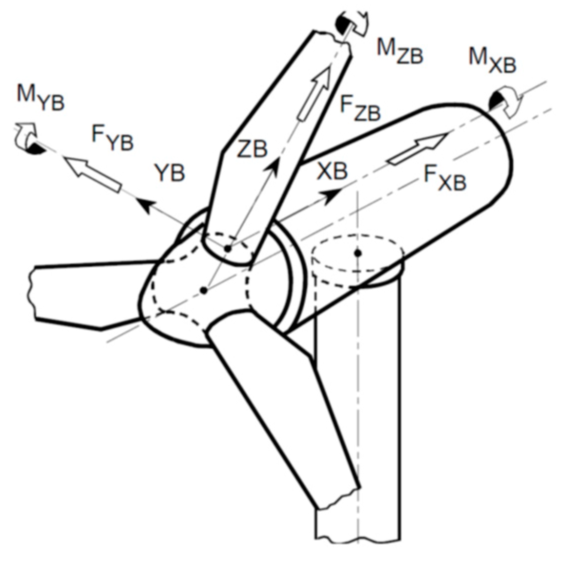
2.2. Structure Model
2.3. Aeroelastic Coupling
3. Verification of the Single Rotor Model
3.1. Model Outline
- Rating: 5 MW.
- Rotor orientation, configuration: Upwind, 3 Blades.
- Rotor Diameter: 126 m.
- Hub Height: 90 m.
- Cut-in, Cut-out Wind Speed: 3 m/s, 25 m/s.
- Rated Wind Speed: 11.4 m/s.
- Rotor Mass: 110,000 kg.
- Nacelle Mass: 240,000 kg.
- Tower Mass: 347,460 kg.
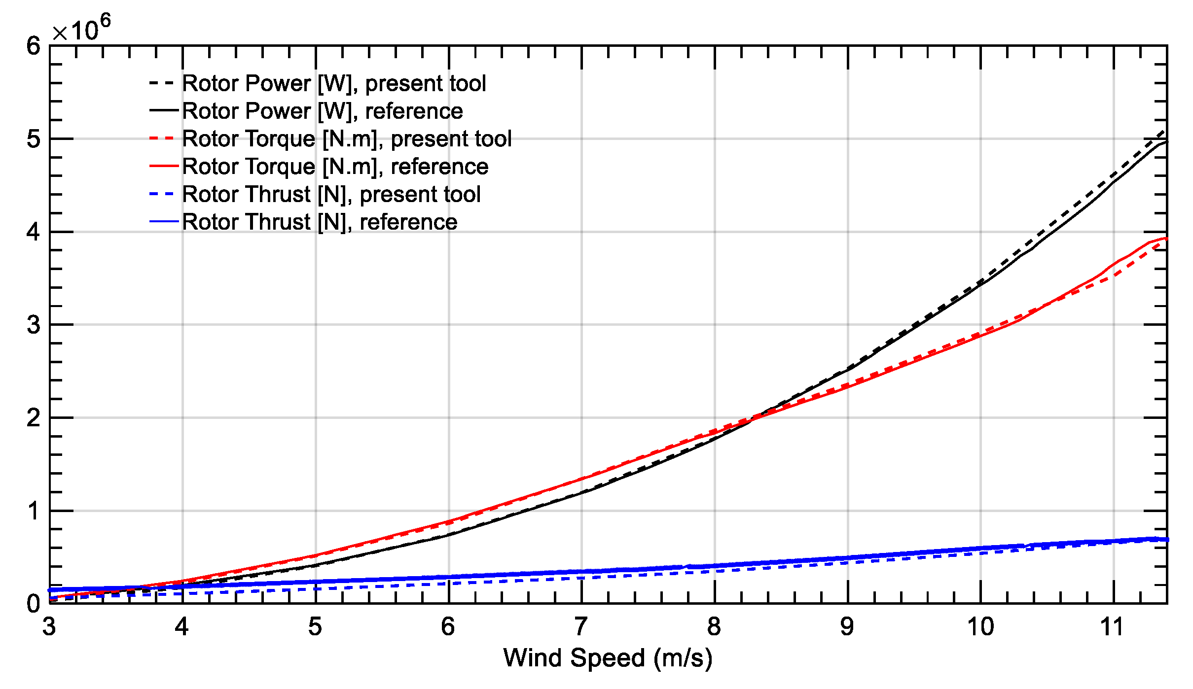
3.2. Rotor Aerodynamics
3.3. Modal Analysis
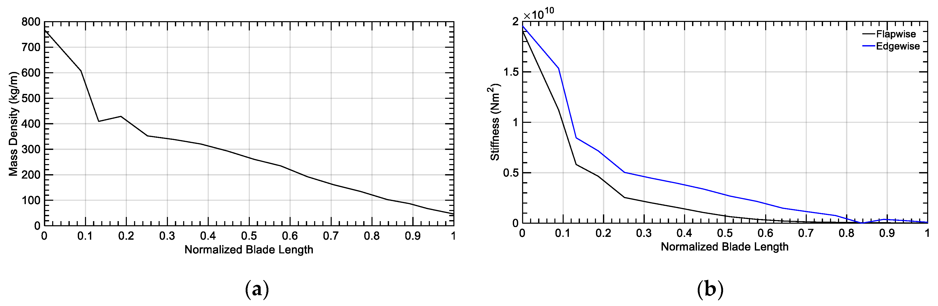
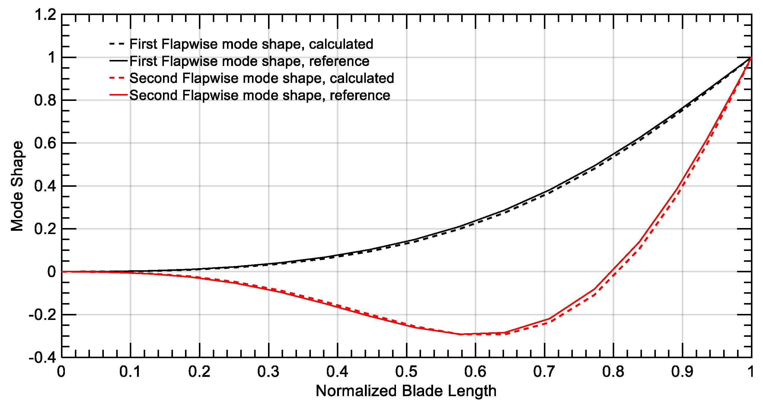
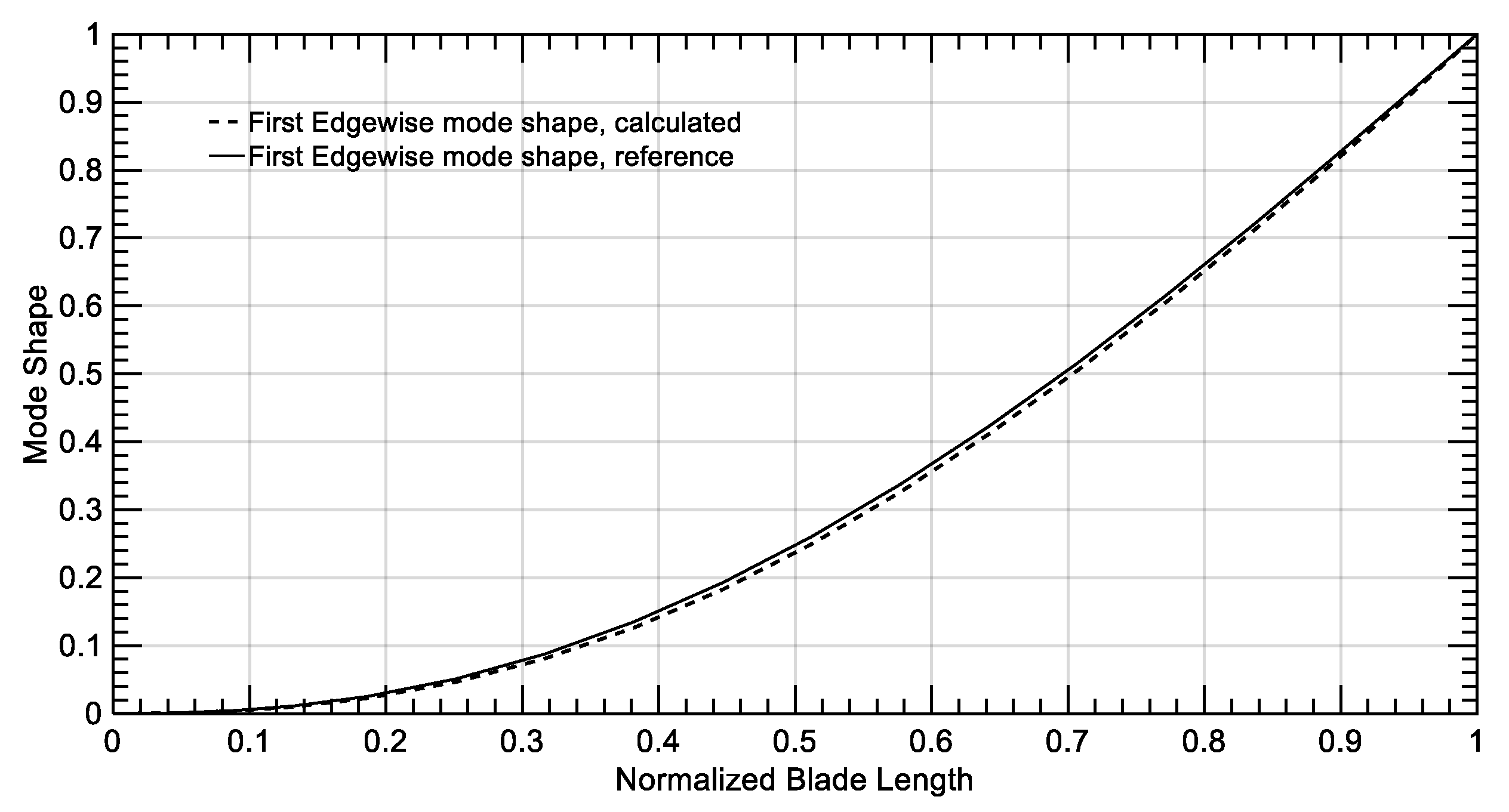
3.3.1. Blades
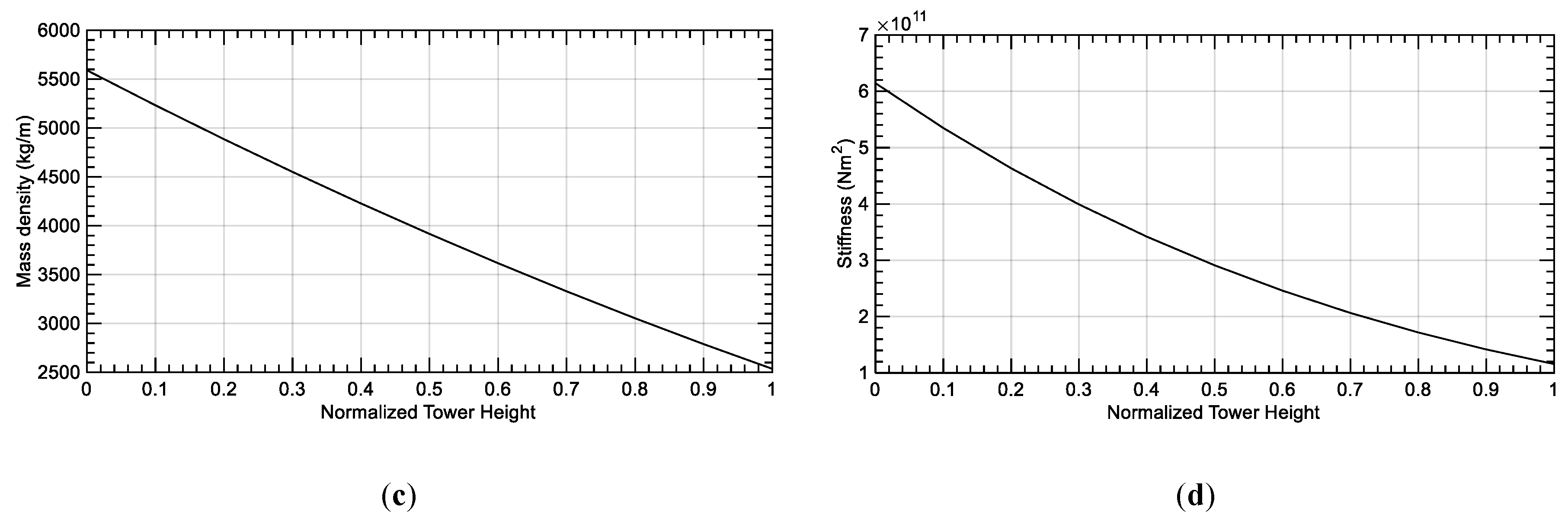
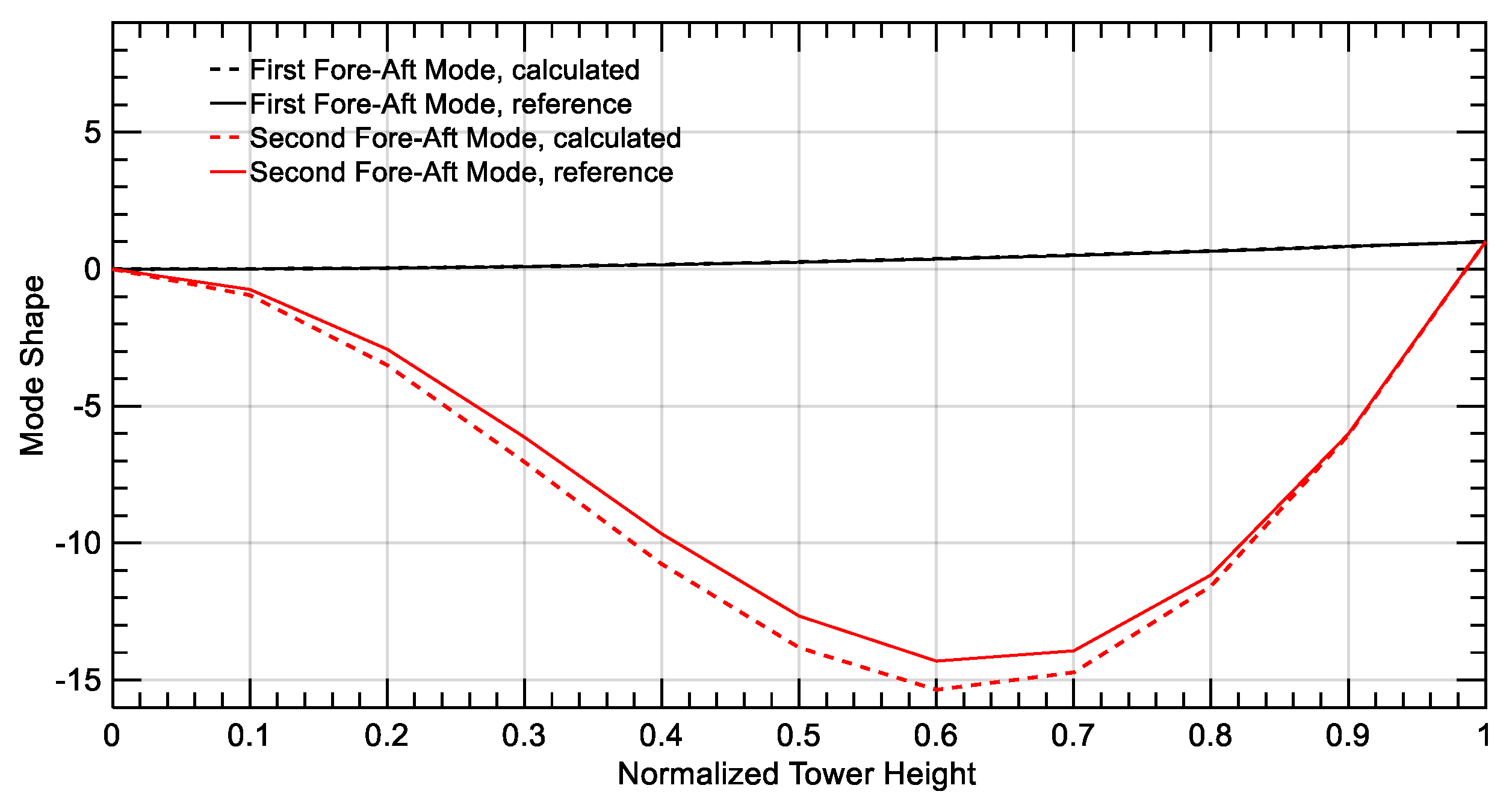
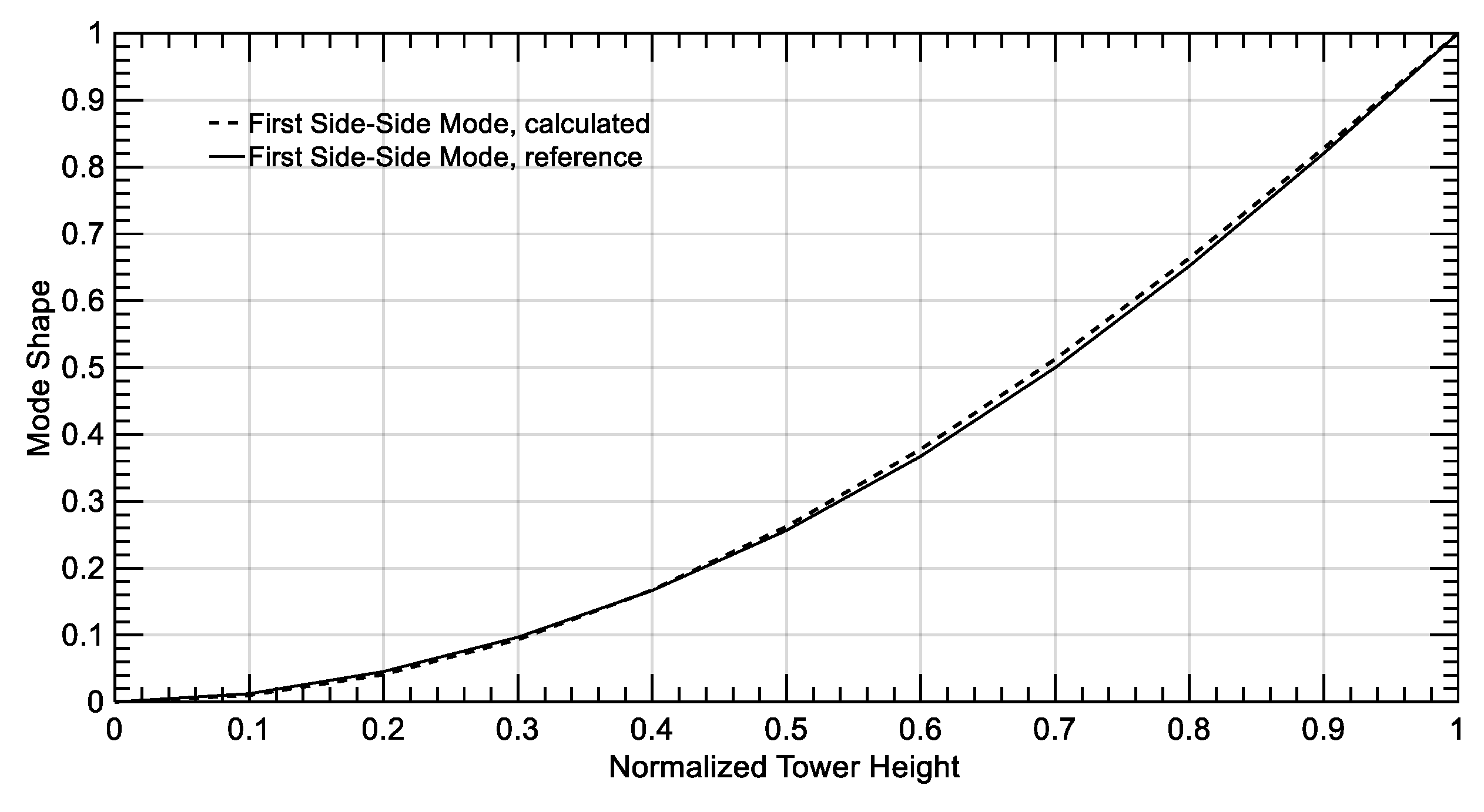
3.3.2. Tower
3.4. Aeroelastic Analysis
- Wind speed: 11.4 m/s (Rated wind speed)
- Rotational velocity: 12.1 rpm
- Pitch angle: 0°
- Time step: 0.01 s
- Simulation time: 50 s
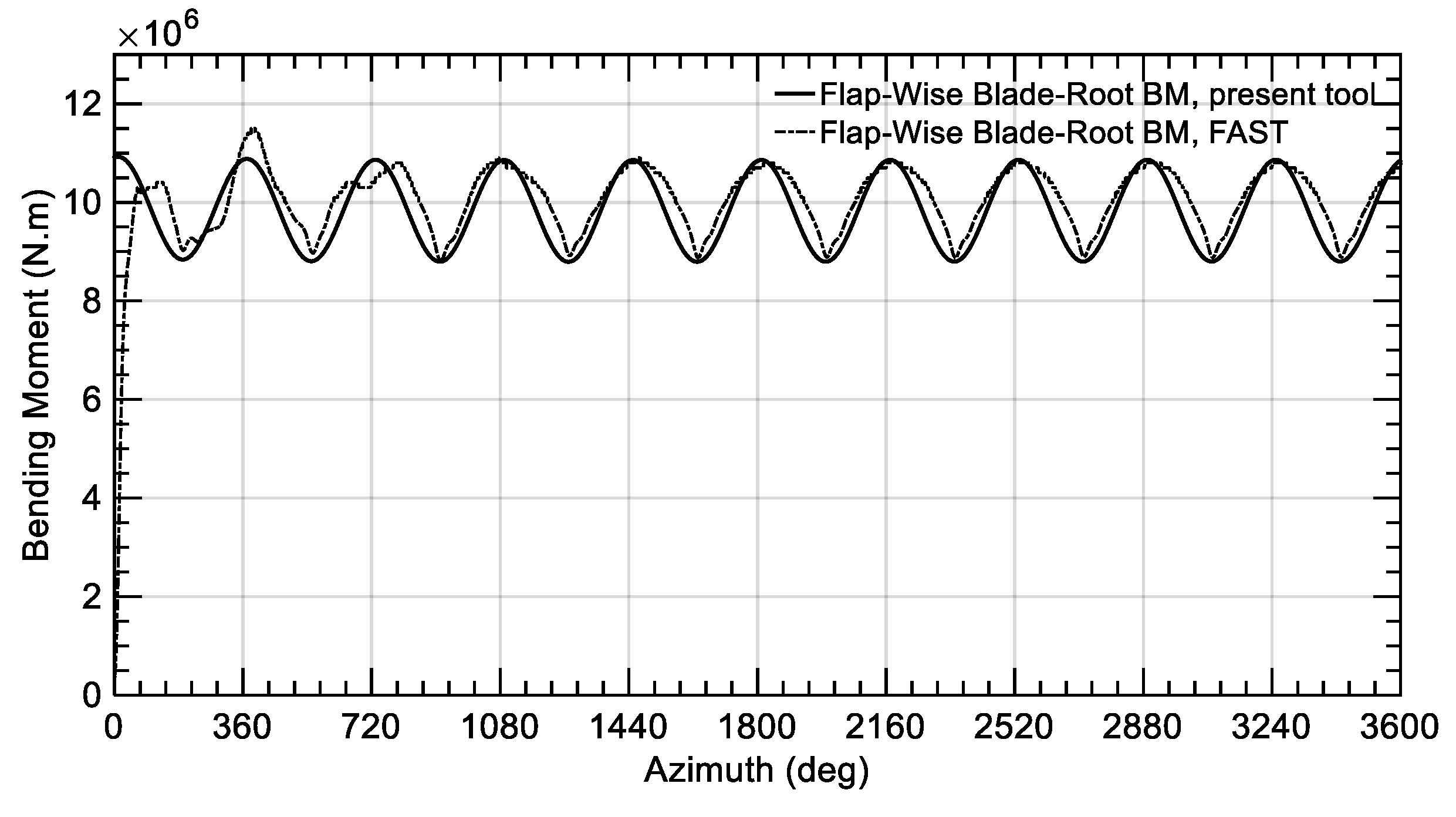
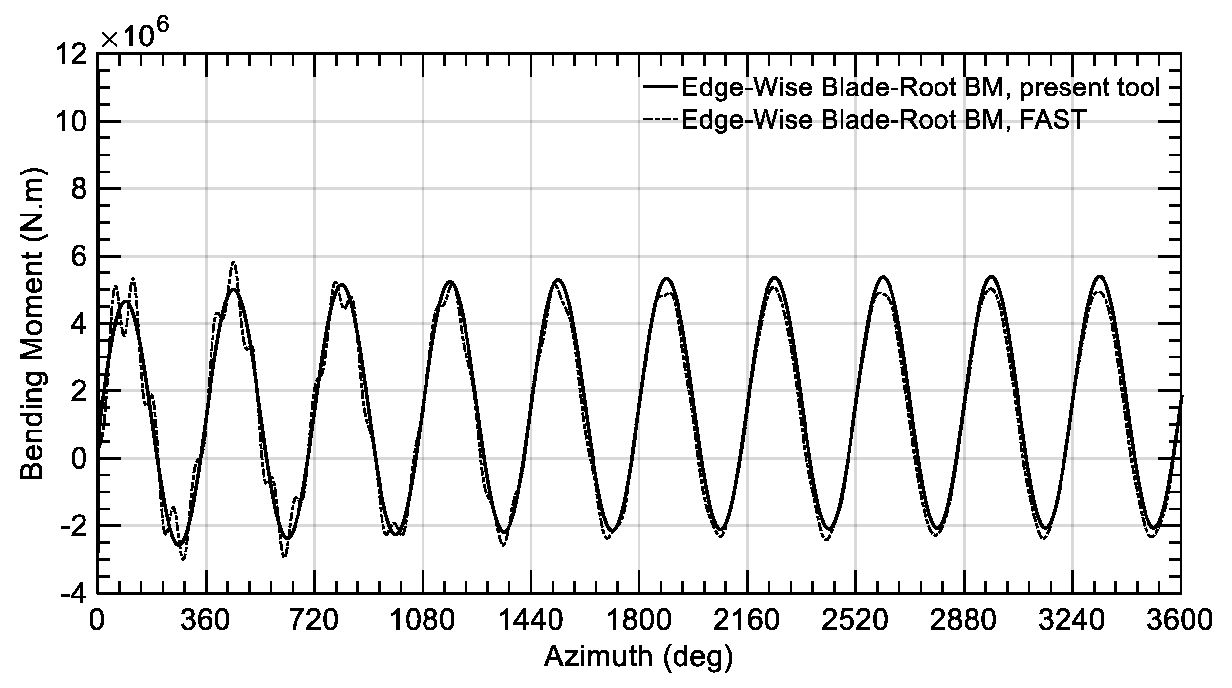
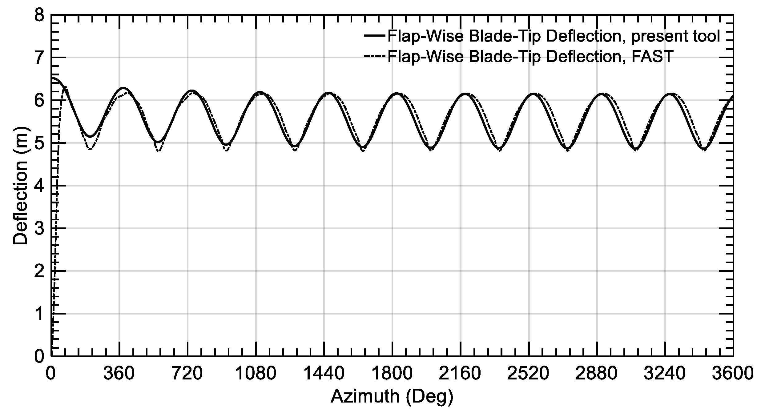
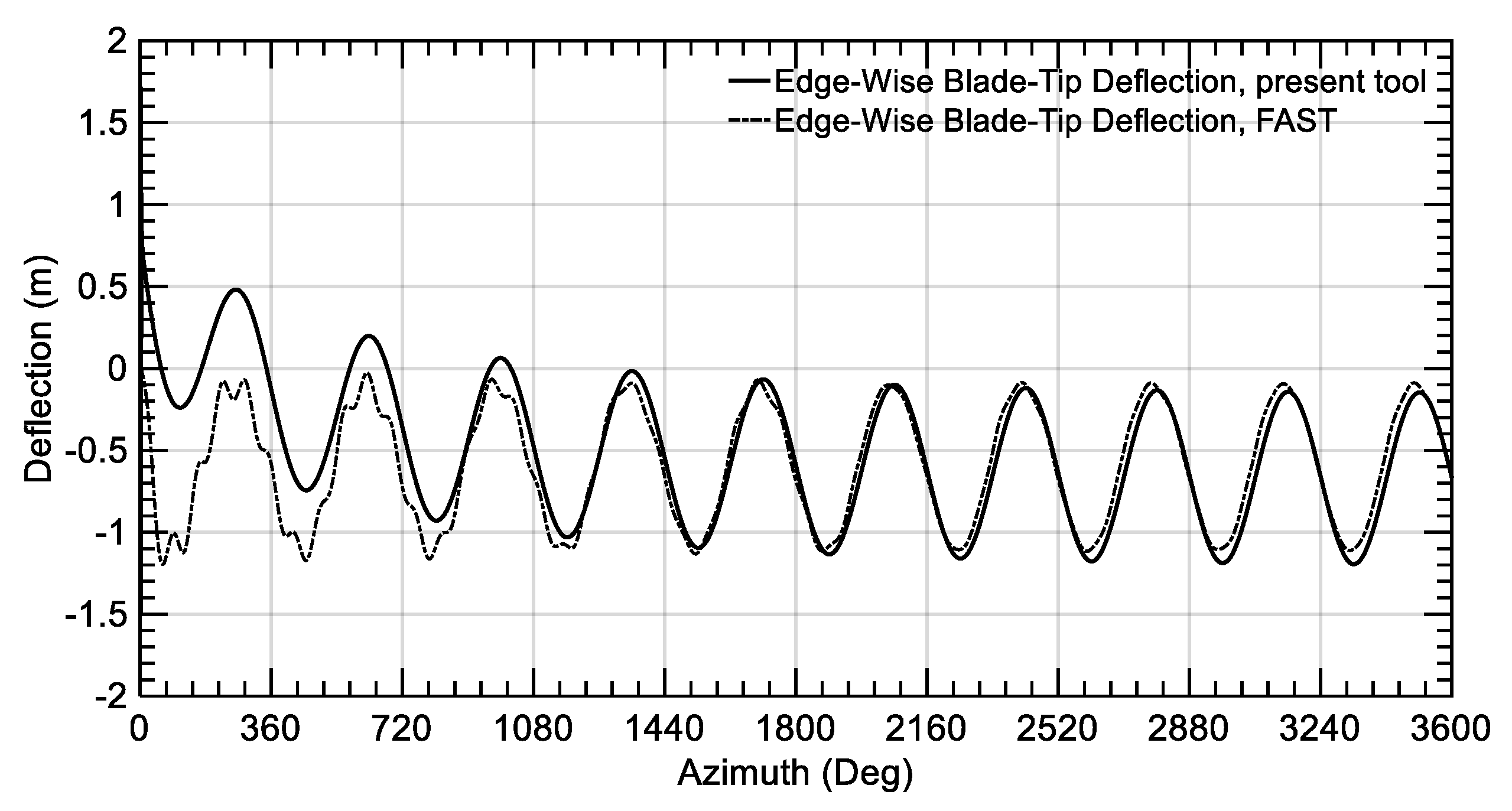
3.4.1. Blades
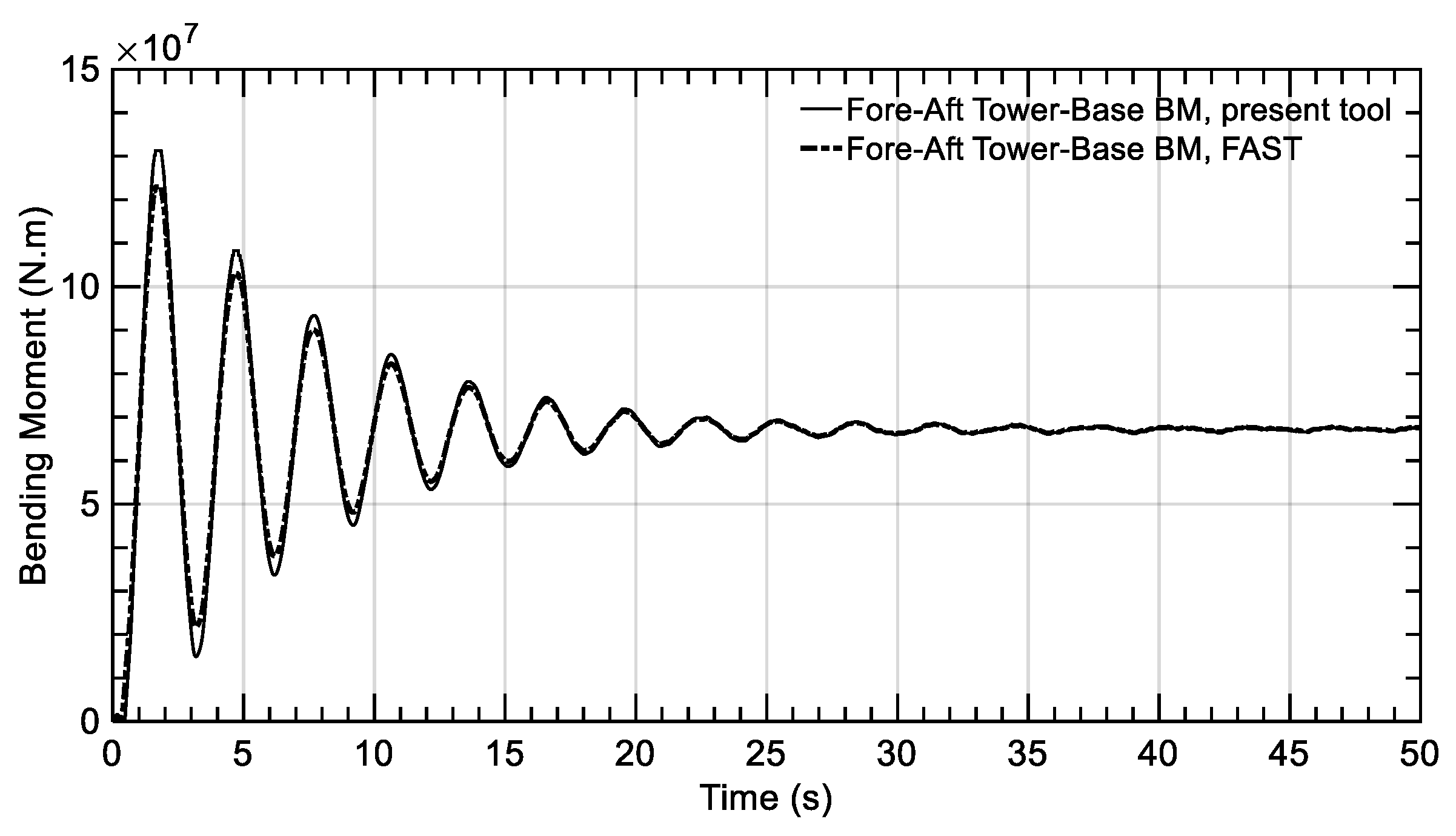
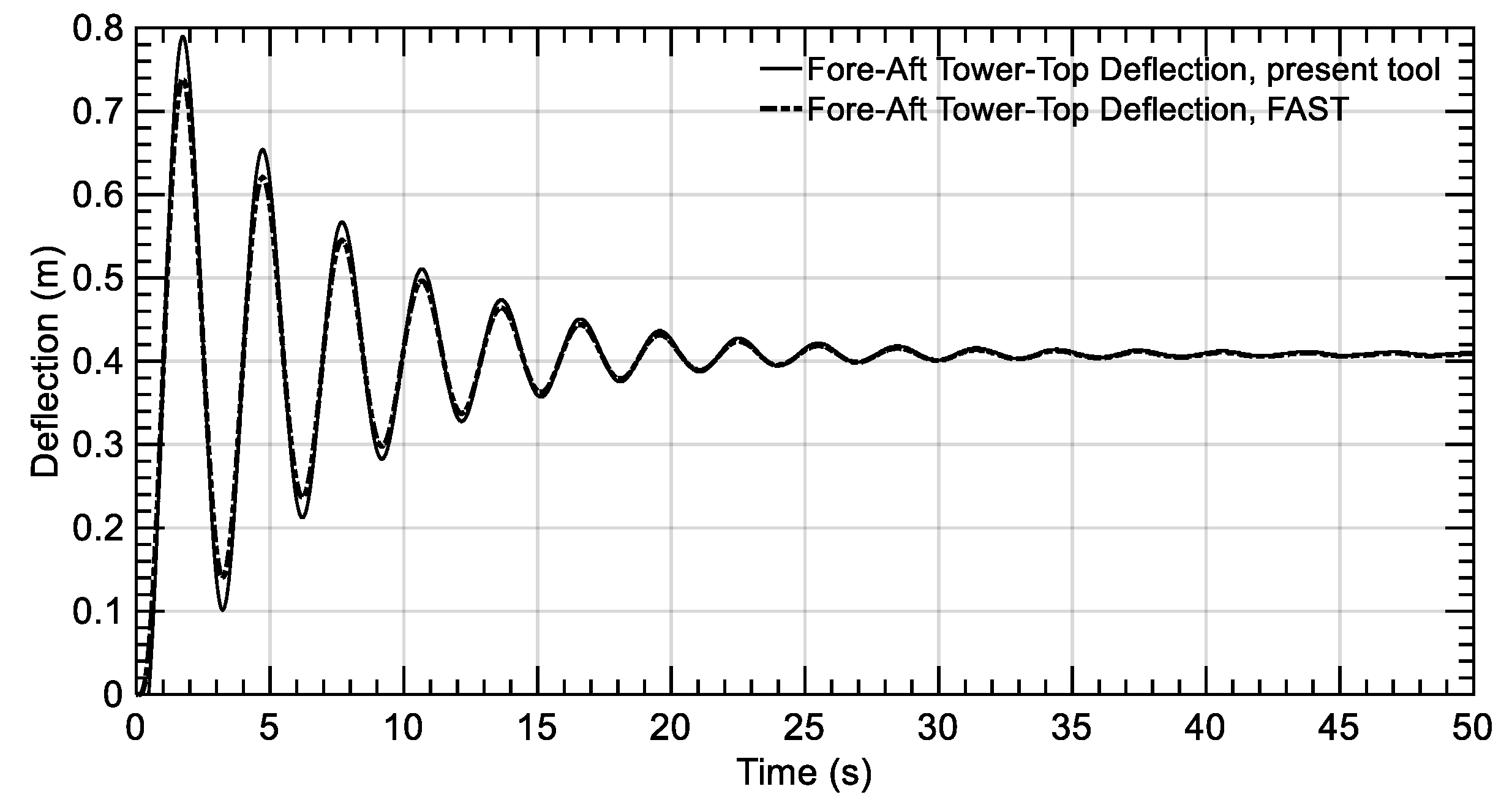
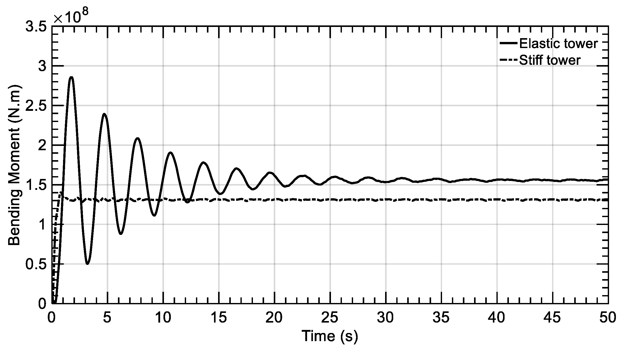
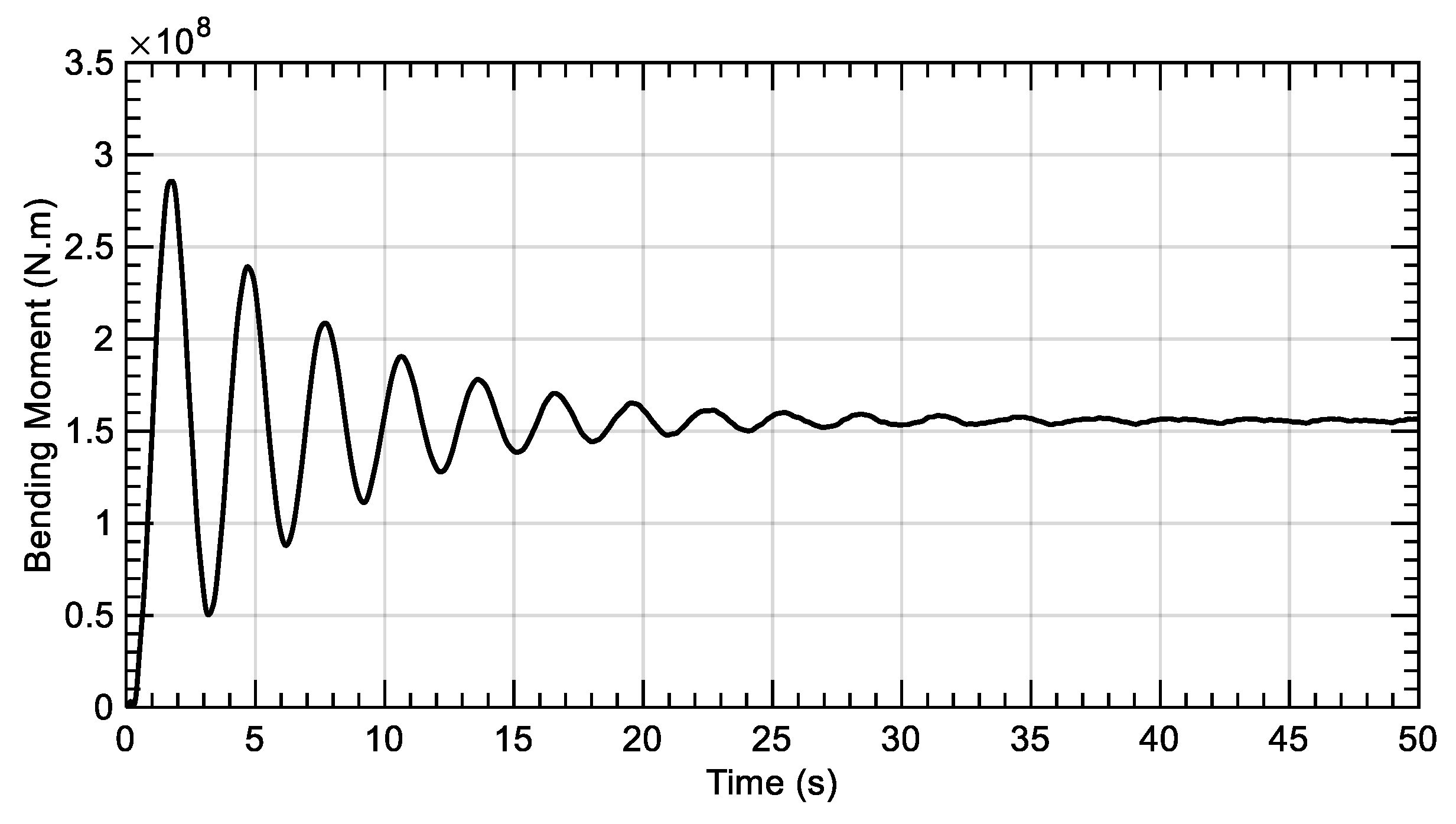
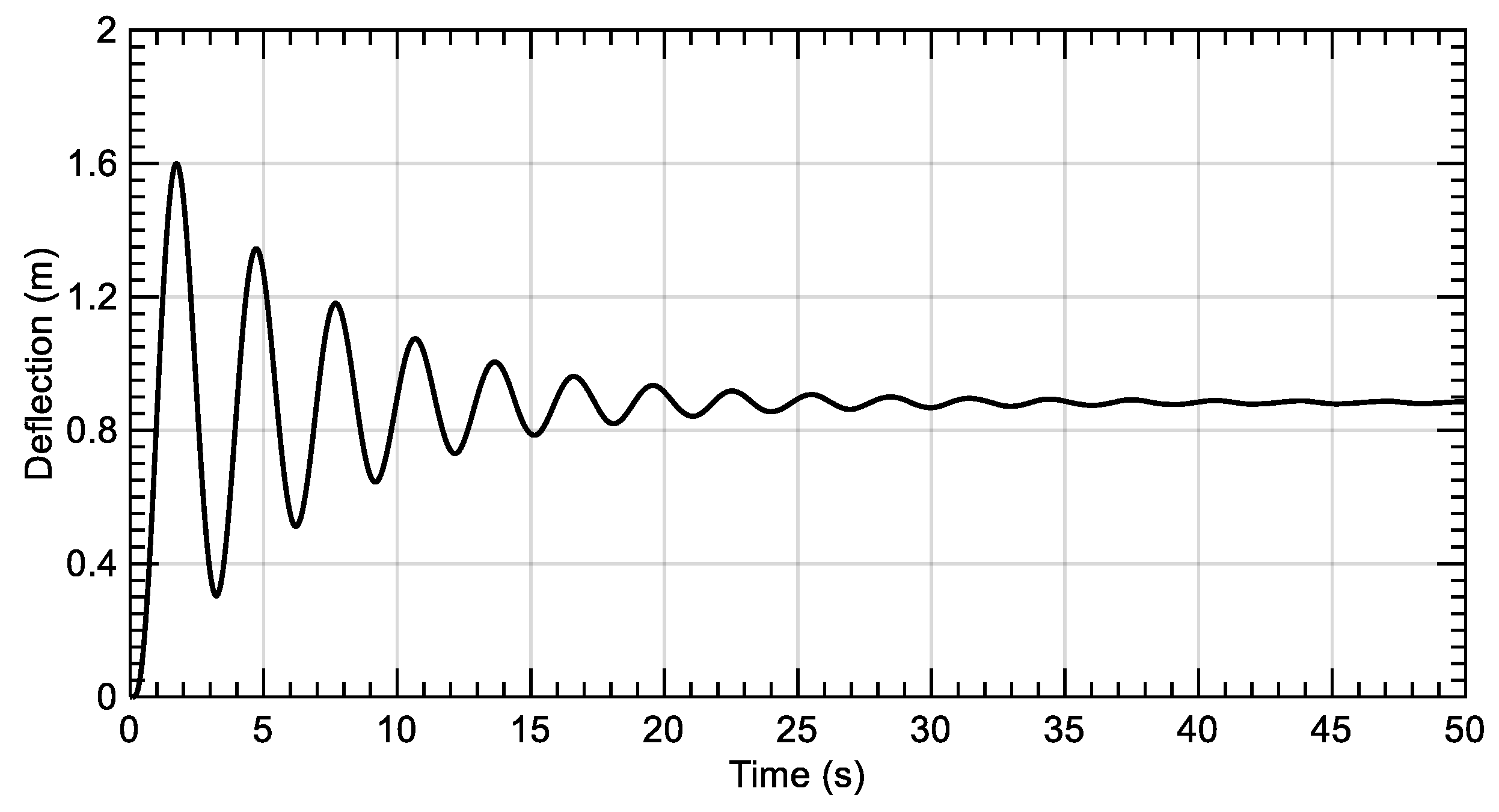
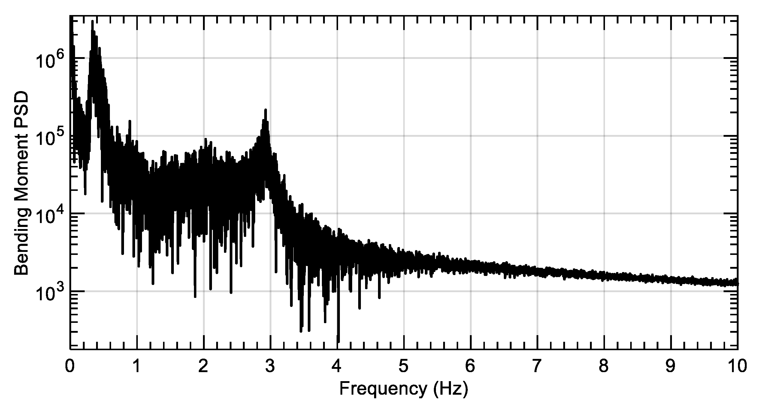
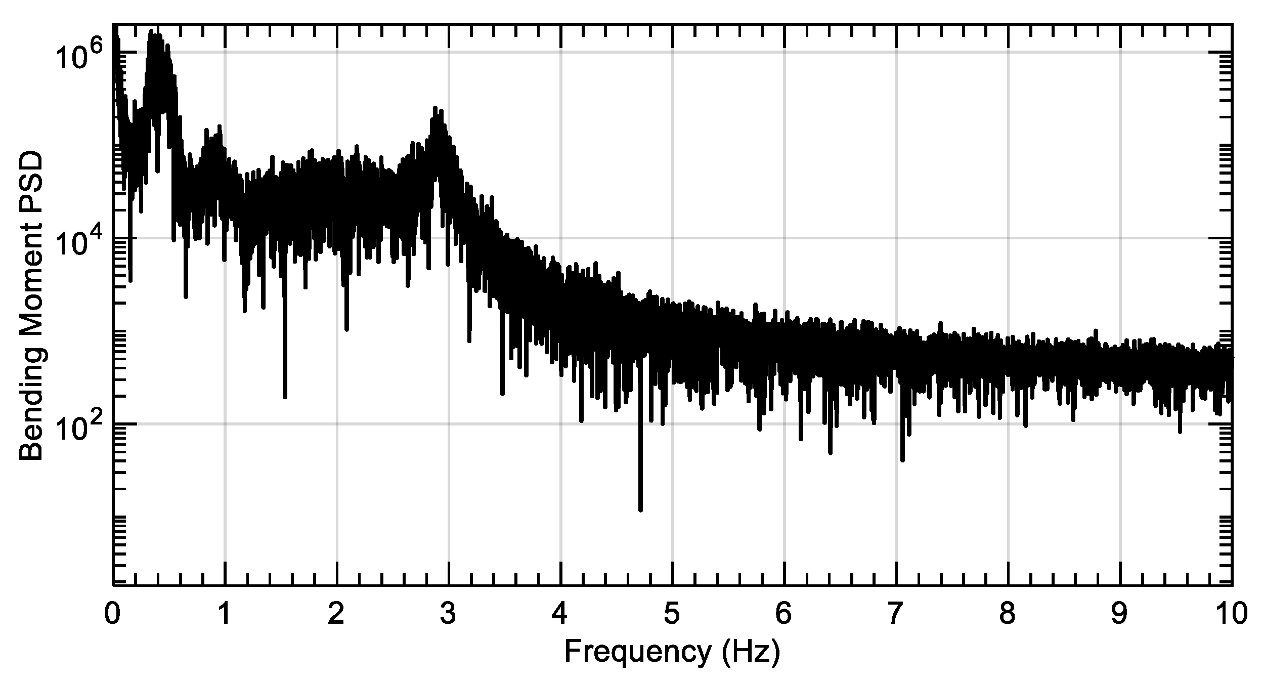
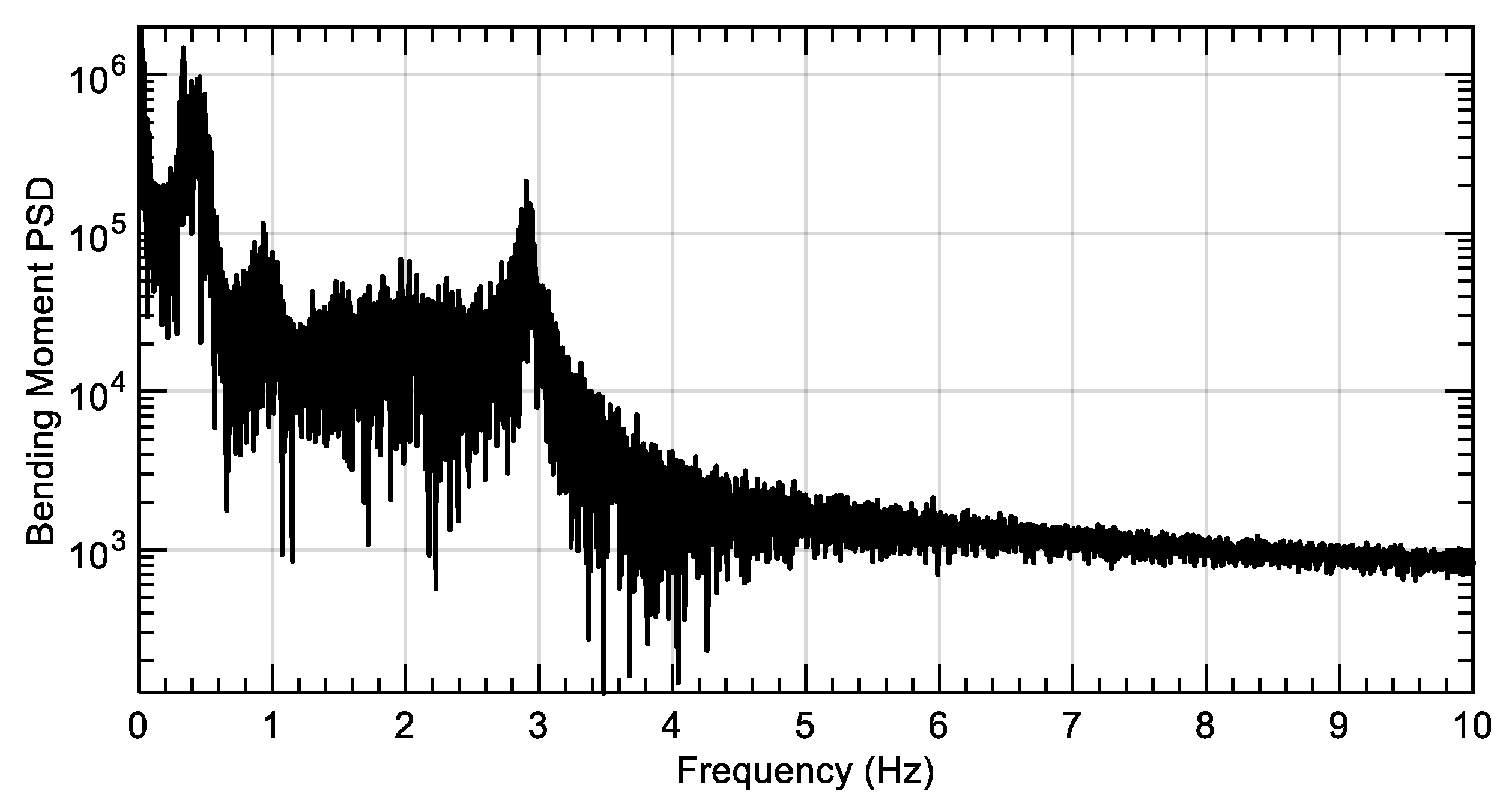
3.4.2. Tower
4. Simulation of the Twin-Rotor Model
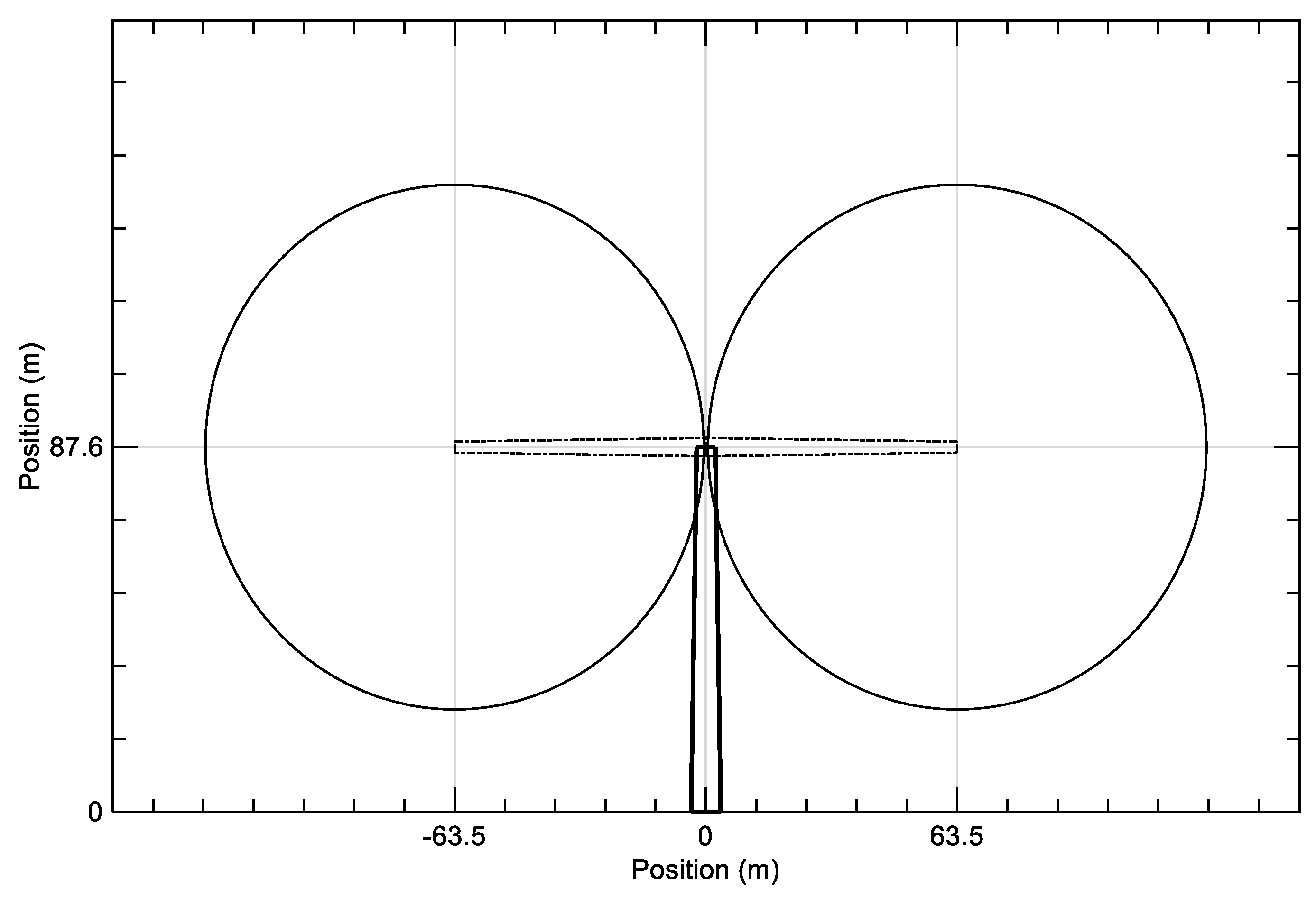
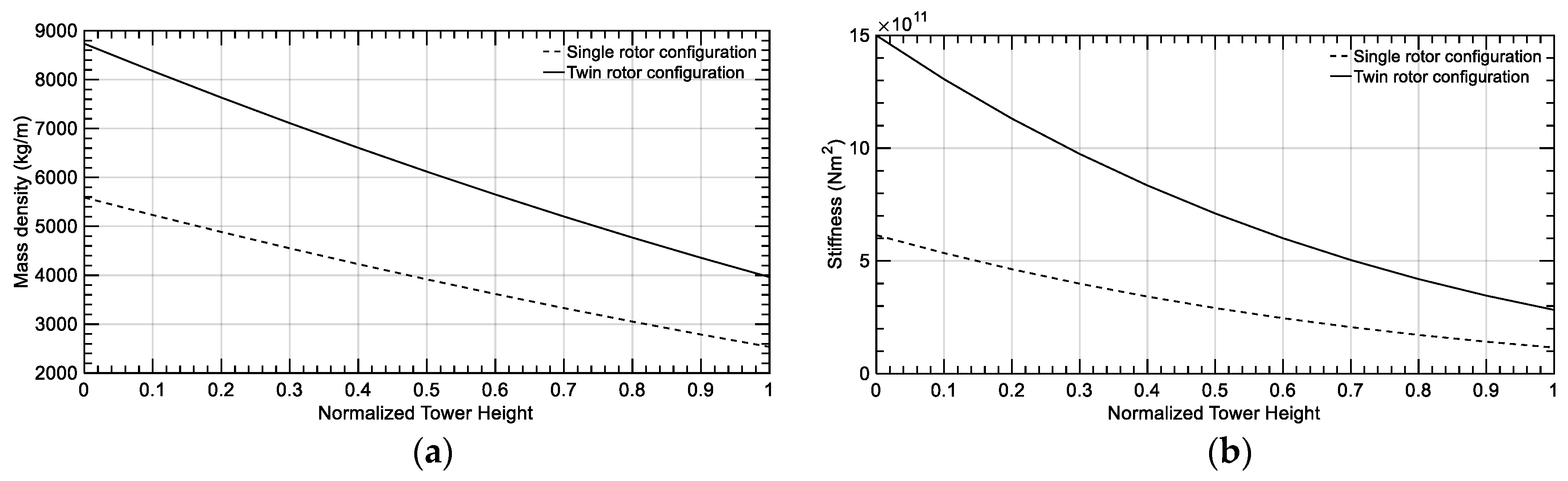
4.1. Twin-Rotor Wind Turbine Model
4.2. Simulation Conditions
4.2.1. Case 1: Steady Flow Condition
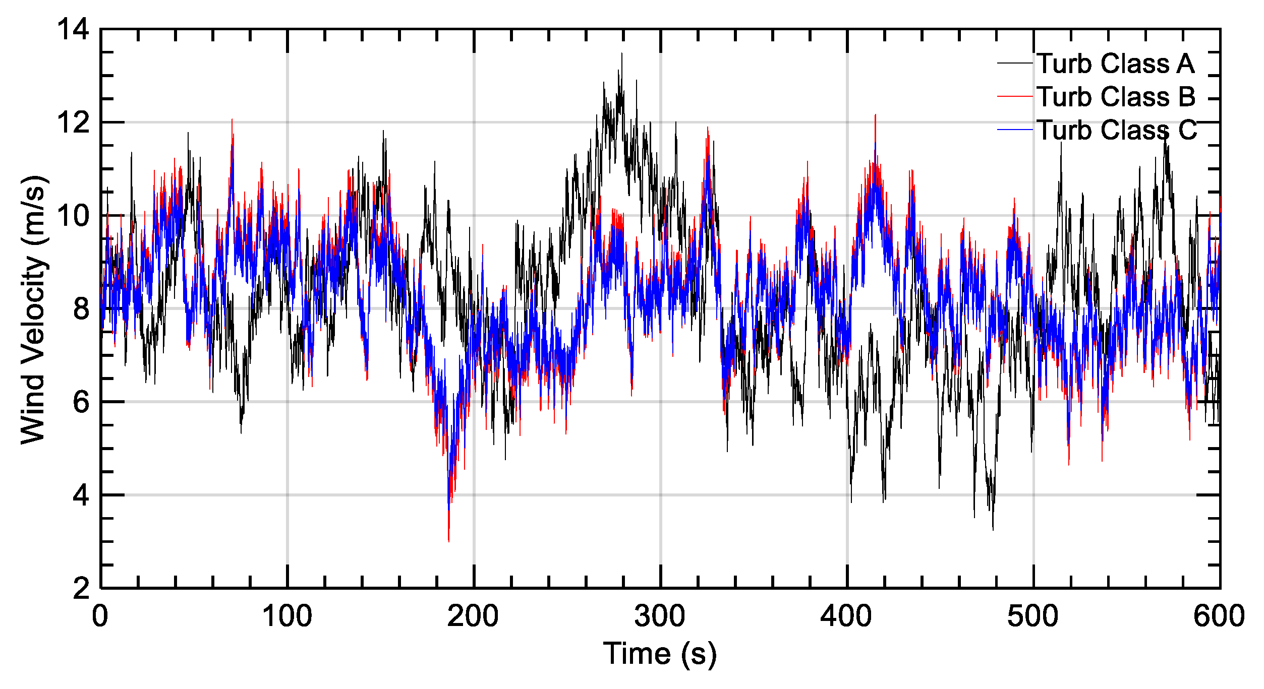
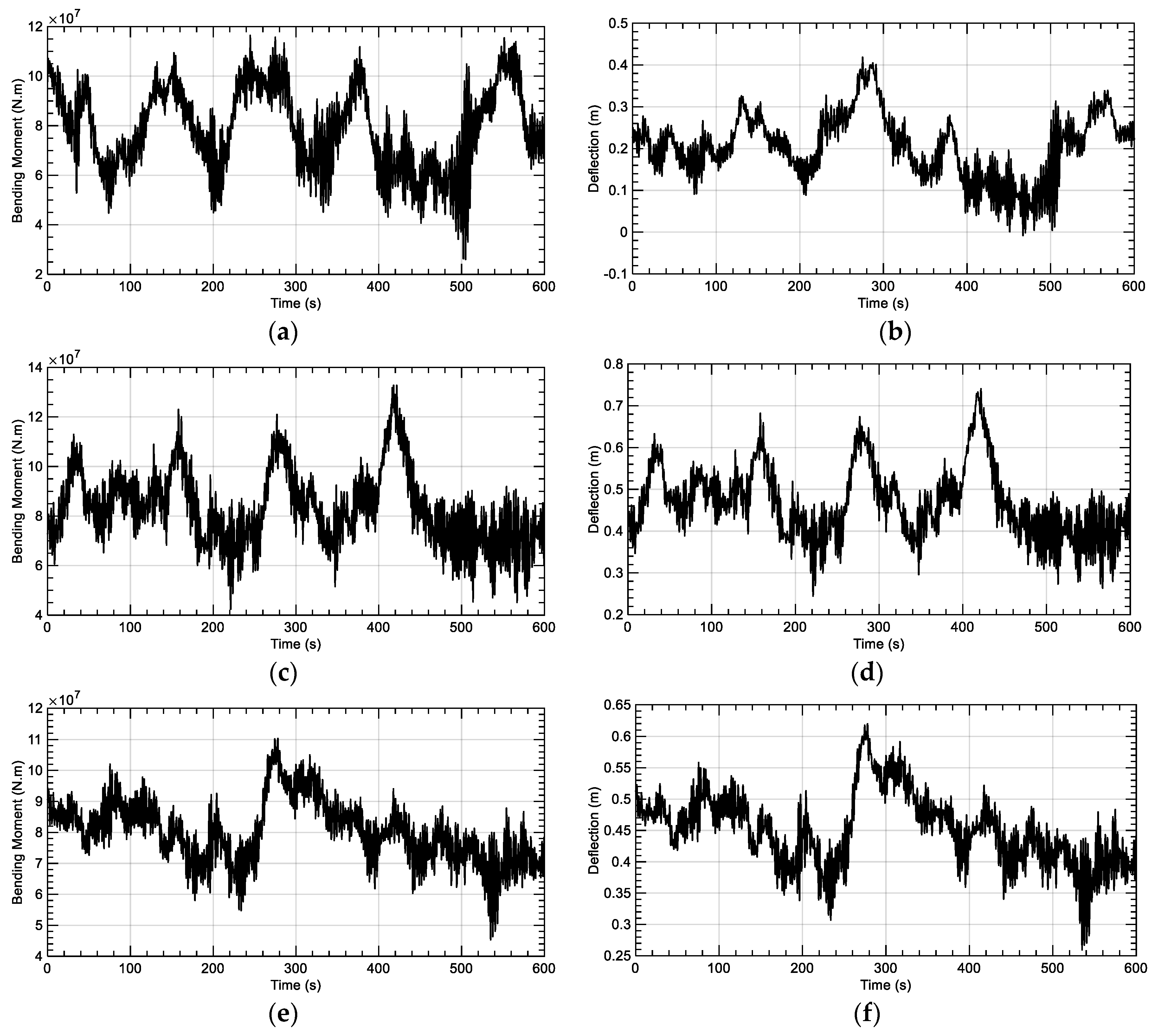
4.2.2. Case 2: Turbulent Flow Condition
5. Conclusions
- The developed tool has been sufficiently validated for a single-rotor configuration when compared to results of FAST analysis. It can be trusted to model a twin-rotor configuration.
- Tower elasticity should be considered when studying the tower dynamics. The stiff tower model does not count for the vibration and hence the inertial loads of the tower, causing misleading results of the loads in terms of value and behavior.
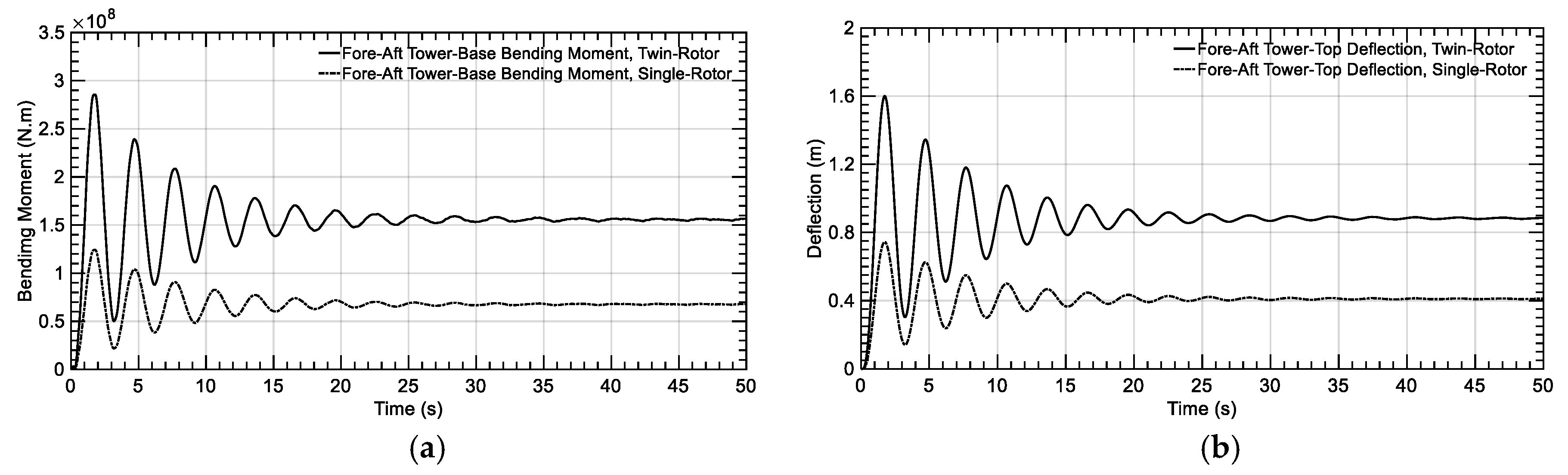
- For a tower with the same first fore-aft natural frequency, if one more rotor is added; it does not only increase the loads, but also changes the natural frequencies of the rotor and hence the stiffness and structural damping. Accordingly, the change in the tower deflections and loads is not straightforward with the number of rotors.
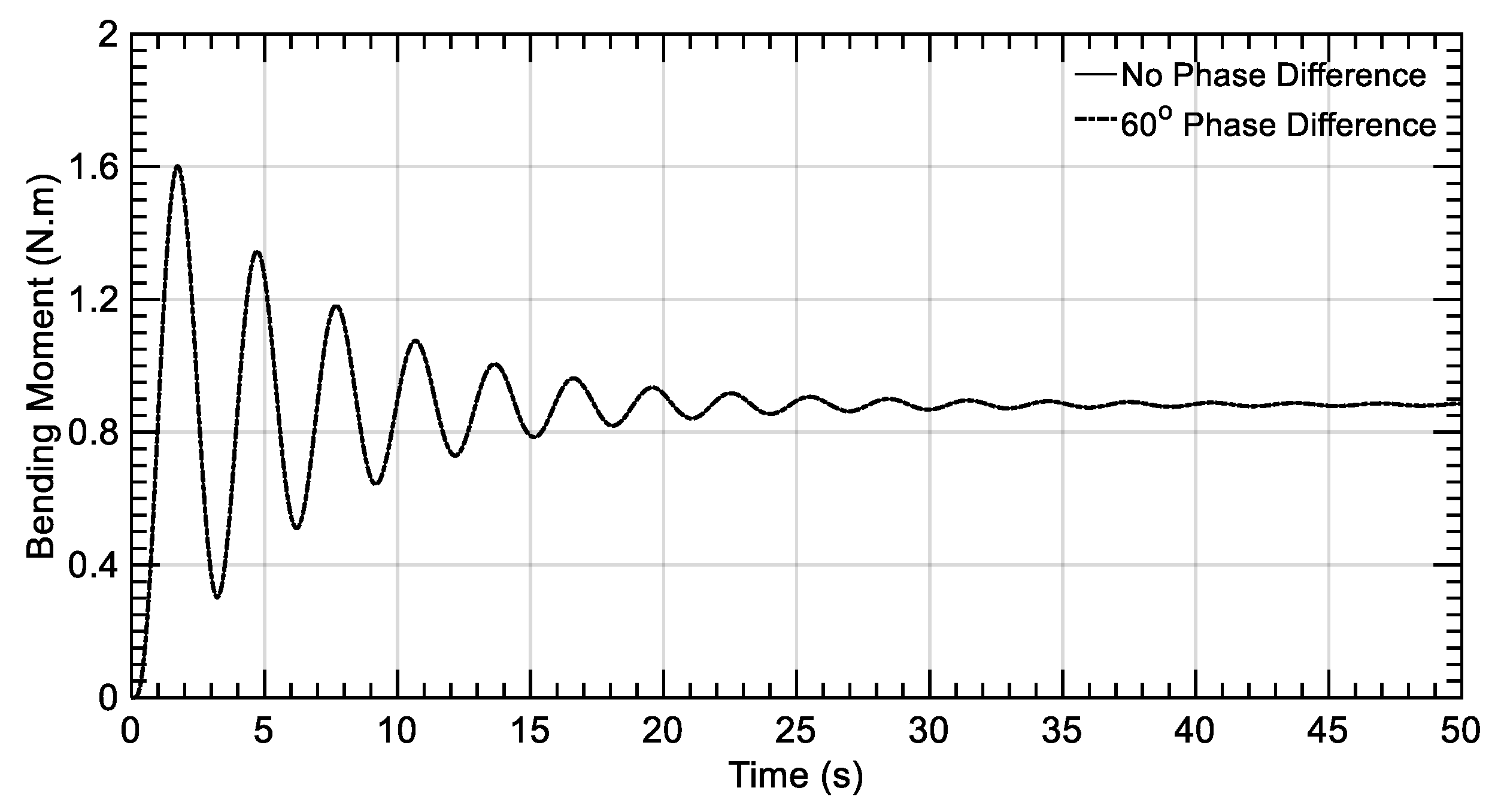
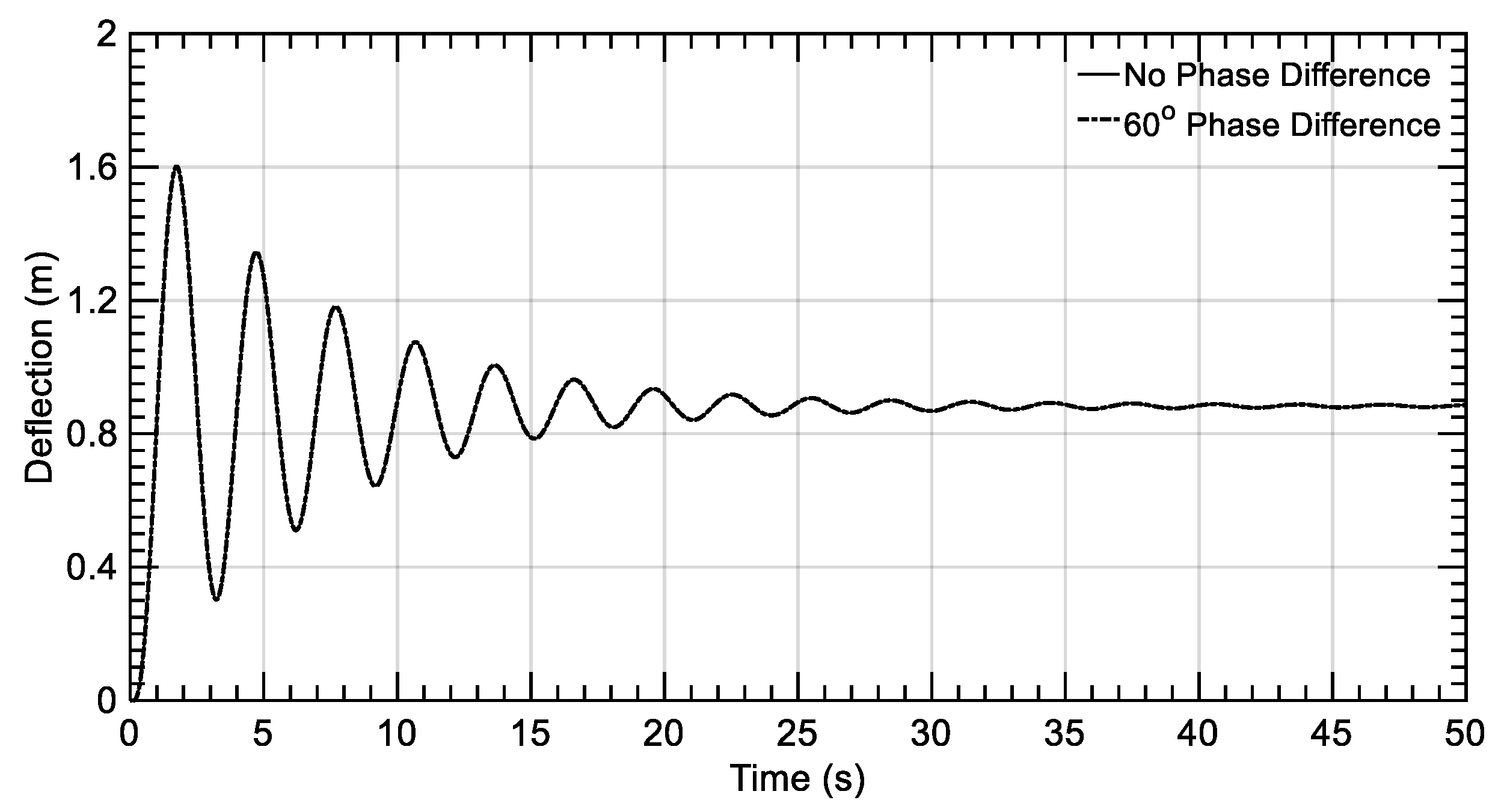
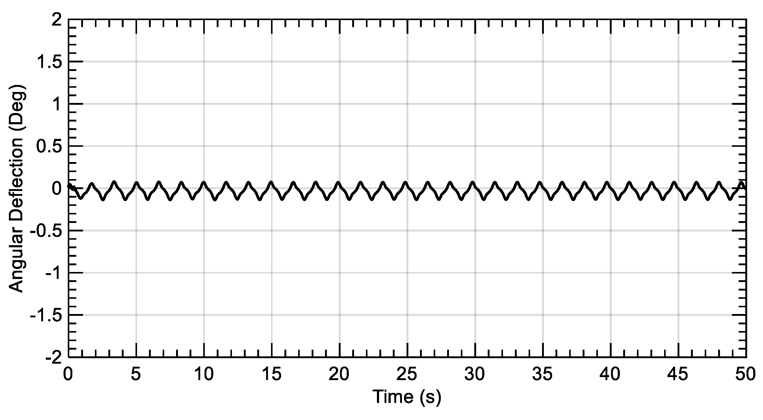
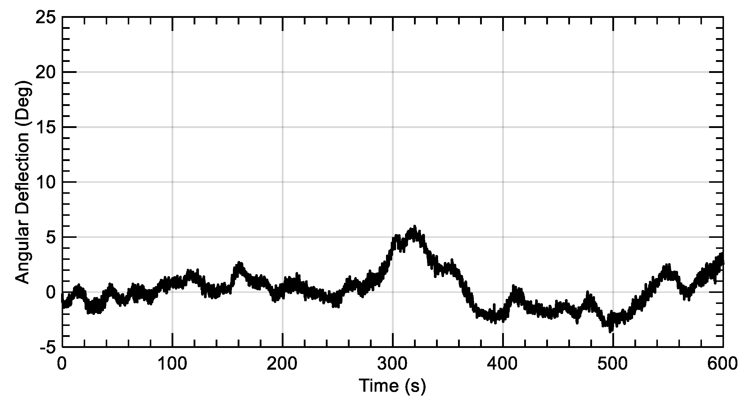
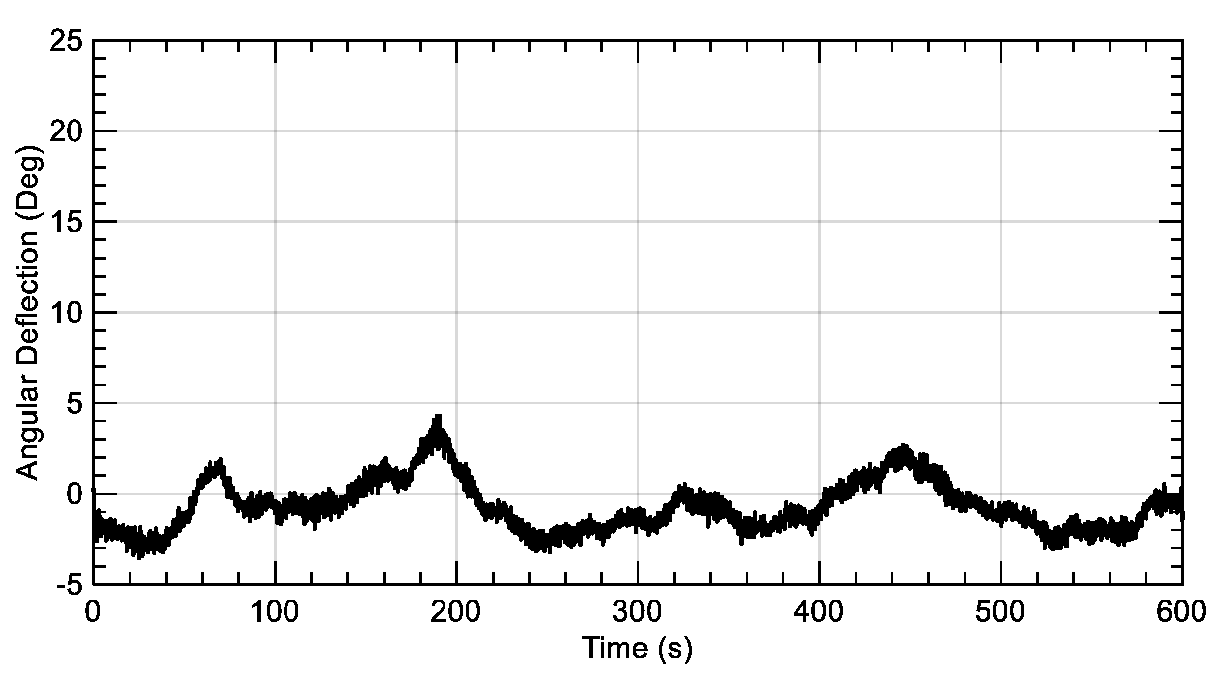
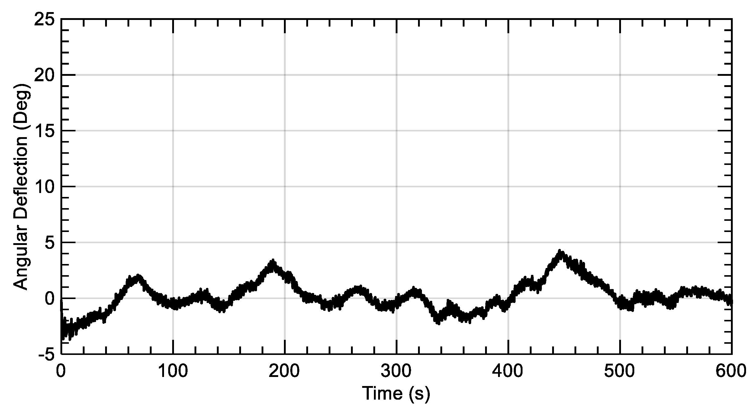
- Tower torsion is very crucial in case of twin-rotor configuration. The normal case is that the two rotors are not rotating simultaneously, and the results of this work have shown yawing deflections of the tower in case there is a slight phase change in the rotor loads’ time series.
- Tower natural frequencies are dominant over the flow conditions for the tower loads and deflections.
Author Contributions
Funding
Acknowledgments
Conflicts of Interest
Abbreviations
| BEM | Blade Element Momentum |
| CAD | Computer Aided Drawing |
| CFD | Computational Fluid Dynamics |
| FAST | Fatigue, Aerodynamics, Structure, Turbulence |
| IEC | International Electrotechnical Commission |
| MRS | Multi Rotor System |
| NREL | National Renewable Energy Laboratory |
References
- Global Wind Energy Council (GWEC). Global Wind Report; Global Wind Energy Council: Brussels, Belgium, 2018. [Google Scholar]
- GE Renewable Energy. Available online: https://www.ge.com/renewableenergy/wind-energy/turbines/haliade-x-offshore-turbine (accessed on 25 January 2019).
- Hofmann, M.; Sperstad, I.B. Will 10 MW wind turbines bring down the operation and maintenance cost of offshore wind farms? Energy Procedia 2014, 53, 231–238. [Google Scholar] [CrossRef]
- Jamieson, P. Multi Rotor Systems. In Innovation in Wind Turbine Design; Wiley-Blackwell: Chichester, UK, 2011. [Google Scholar]
- Goltenbott, U.; Ohya, U.; Yoshida, S.; Jamieson, P. Aerodynamic interaction of diffuser augmented wind turbines in multi-rotor systems. Renew. Energy 2017, 112, 25–34. [Google Scholar] [CrossRef]
- Chasapogiannis, P.; Prospathopoulos, J.M.; Voutsinas, S.G.; Chaviaropoulos, T.K. Analysis of the aerodynamic performance of the multi-rotor concept. J. Phys. Conf. Ser. 2014, 524, 012084. [Google Scholar] [CrossRef]
- Yoshida, S.; Goltenbott, U.; Ohya, Y.; Jamieson, P. Coherence Effects on the Power and Tower Loads of a 7 × 2 MW Multi-Rotor Wind Turbine System. Energies 2016, 9, 742. [Google Scholar] [CrossRef]
- Ghaisas, N.S.; Ghate, A.S.; Lele, S.K. Large-eddy simulation study of multi-rotor wind turbines. J. Phys. Conf. Ser. 2018, 1037, 072021. [Google Scholar] [CrossRef]
- Van der Laan, M.P.; Andersen, S.J.; García, N.R.; Angelou, N.; Pirrung, G.R.; Ott, S.; Sjöholm, M.; Sørensen, K.H.; Neto, J.X.V.; Kelly, M.; et al. Power curve and wake analyses of the Vestas multi-rotor demonstrator. Wind Energy Sci. 2019, 44. [Google Scholar] [CrossRef]
- Verma, P. Multi Rotor Wind Turbine Design and Cost Scaling. Master’s Thesis, University of Massachusetts Amherst, Amherst, MA, USA, September 2013. [Google Scholar]
- Mate, G.M. Development of a Support Structure for Multi-Rotor Wind Turbines. Master’s Thesis, University of Massachusetts Amherst, Amherst, MA, USA, September 2014. [Google Scholar]
- Bazilevs, Y.; Yan, J.; Deng, X.; Korobenko, A. Computer Modeling of Wind Turbines: 2. Free-Surface FSI and Fatigue-Damage. In Archives of Computational Methods in Engineering; Springer: Dordrecht, The Netherlands, 2018. [Google Scholar]
- Halawa, A.; Sessarego, M.; Shen, W.Z.; Yoshida, S. Numerical Fluid-Structure Interaction Study on the NREL 5MW HAWT. J. Phys. Conf. Ser. 2018, 1037, 022026. [Google Scholar] [CrossRef]
- Jonkman, J. The New Modularization Framework for the FAST Wind Turbine CAE Tool. In Proceedings of the 51st AIAA Aerospace Sciences Meeting, Grapevine, TX, USA, 7–10 January 2013. [Google Scholar]
- Vorpahl, F.; Popko, W. Description of the Load Cases and Output Sensors to be Simulated in the OC4 Project under IEA Wind Annex 30; Fraunhofer Institute for Wind Energy and Energy System Technology IWES: Bremerhaven, Germany, 2016. [Google Scholar]
- Hansen, M.O.L. Unsteady BEM Model. In Aerodynamics of Wind Turbines, 2nd ed.; Earthscan: London, UK, 2008; pp. 85–102. [Google Scholar]
- Hansen, M.O.L. Dynamic Structural Model of a Wind Turbine. In Aerodynamics of Wind Turbines, 2nd ed.; Earthscan: London, UK, 2008; pp. 125–138. [Google Scholar]
- Jonkman, J.; Butterfield, S.; Musial, W.; Scott, G. Definition of a 5-MW Reference Wind Turbine for Offshore System Development; NREL Technical Report TP-500-38060; National Renewable Energy Lab: Golden, CO, USA, 2009. [Google Scholar]
- Bazilevs, Y.; Hsu, M.C.; Akkerman, I.; Wright, S.; Takizawa, K.; Henicke, B.; Spielman, T.; Tezduyar, T.E. 3D Simulation of Wind Turbine Rotors at Full Scale. Part I: Geometry Modeling and Aerodynamics. Int. J. Numer. Methods Fluids 2011, 65, 207–235. [Google Scholar] [CrossRef]
- NWTC Information Portal (Modes). Available online: https://nwtc.nrel.gov/Modes (accessed on 15 May 2019).
- Jonkman, B.J.; Kilcher, L. TurbSim’s User Guide: Version 1.06.00; Technical Report; National Renewable Energy Lab (NREL): Golden, CO, USA, 2012. [Google Scholar]
- IEC. Wind Turbines—Part 1: Design RequirementsIEC-61400-1, 3rd ed.; International Electrotechnical Commission: Geneva, Switzerland, 2005. [Google Scholar]


| Mode | Calculated (Hz) | Reference (Hz) | Deviation (%) |
|---|---|---|---|
| First flap-wise | 0.71 | 0.70 | 1.4 |
| Second flap-wise | 2.02 | 2.02 | 0.0 |
| First edge-wise | 1.08 | 1.08 | 0.0 |
| Mode | Calculated (Hz) | Reference (Hz) | Deviation (%) |
|---|---|---|---|
| First fore-aft | 0.32 | 0.32 | 0.0 |
| Second fore-aft | 3.06 | 2.90 | 5.2 |
| First side-side | 0.32 | 0.31 | 3.1 |
| Property (m) | Single rotor | Twin rotor |
|---|---|---|
| Tower base diameter | 6.000 | 7.500 |
| Tower base thickness | 0.027 | 0.027 |
| Tower top diameter | 3.870 | 4.840 |
| Tower top thickness | 0.019 | 0.019 |
| Tower height | 87.600 | 87.600 |
| Mode | Single rotor (Hz) | Twin rotor (Hz) | Deviation (%) |
|---|---|---|---|
| First fore-aft | 0.32 | 0.32 | 0.0 |
| Second fore-aft | 3.06 | 3.20 | 4.4 |
| First side-side | 0.32 | 0.25 | 21.8 |
| Turbulence Class | Mean Value | Standard Deviation | Dominant Frequencies |
|---|---|---|---|
| A | 8.00 × 10⁷ | 1.79 × 10⁷ | 0.32 Hz and 3 Hz |
| B | 8.25 × 10⁷ | 1.53 × 10⁷ | 0.32 Hz and 3 Hz |
| C | 8.06 × 10⁷ | 1.14 × 10⁷ | 0.32 Hz and 3 Hz |
© 2019 by the authors. Licensee MDPI, Basel, Switzerland. This article is an open access article distributed under the terms and conditions of the Creative Commons Attribution (CC BY) license (http://creativecommons.org/licenses/by/4.0/).
Share and Cite
Ismaiel, A.; Yoshida, S. Aeroelastic Analysis of a Coplanar Twin-Rotor Wind Turbine. Energies 2019, 12, 1881. https://doi.org/10.3390/en12101881
Ismaiel A, Yoshida S. Aeroelastic Analysis of a Coplanar Twin-Rotor Wind Turbine. Energies. 2019; 12(10):1881. https://doi.org/10.3390/en12101881
Chicago/Turabian StyleIsmaiel, Amr, and Shigeo Yoshida. 2019. "Aeroelastic Analysis of a Coplanar Twin-Rotor Wind Turbine" Energies 12, no. 10: 1881. https://doi.org/10.3390/en12101881
APA StyleIsmaiel, A., & Yoshida, S. (2019). Aeroelastic Analysis of a Coplanar Twin-Rotor Wind Turbine. Energies, 12(10), 1881. https://doi.org/10.3390/en12101881