Article

Response-Based Assessment of Operational Limits for Mating Blades on Monopile-Type Offshore Wind Turbines

1
Department of Marine Technology, Norwegian University of Science and Technology (NTNU), NO-7491 Trondheim, Norway
2
Centre for Research-based Innovation of Marine Operations (SFI MOVE), NTNU, NO-7491 Trondheim, Norway
3
Department of Engineering Sciences, University of Adger, NO-4879 Grimstad, Norway
4
Department of Mechanical and Industrial Engineering, NTNU, Richard Birkelands vei 2B, NO-7034 Trondheim, Norway
*
Author to whom correspondence should be addressed.
Energies 2019, 12(10), 1867; https://doi.org/10.3390/en12101867
Submission received: 3 April 2019 / Revised: 7 May 2019 / Accepted: 13 May 2019 / Published: 16 May 2019

Abstract

:
Installation of wind-turbine blades on monopile-type offshore wind turbines is a demanding task. Typically, a jack-up crane vessel is used, and blades are individually lifted from the vessel deck and docked with the preinstalled hub. During the process of mating, large relative motions are developed between the hub and root due to combined effects of wind-generated blade-root responses and wave-generated monopile vibrations. This can cause impact loads at the blade root and induce severe damages at the blade-root connection. Such events are highly likely to cause the failure of the mating task, while affecting the subsequent activities, and thus require competent planning. The purpose of this paper is to present a probabilistic response-based methodology for estimating the allowable sea states for planning a wind-turbine blade-mating task, considering impact risks with the hub as the hazardous event. A case study is presented where the installation system consisting of blade-lift and monopile system are modelled using multibody formulations. Time-domain analyses are carried out for various sea states, and impact velocities between root and hub are analyzed. Finally, an extreme value analysis using the Gumbel fitting of response parameters is performed and limiting sea state curves are obtained by comparing characteristic extreme responses with allowable values. It is found that the limiting sea states for blade-root mating tasks are low for aligned wind–wave conditions, and further increase with increased wind–wave misalignment. The results of the study also show that the parameter T p is essential for estimating limiting sea states given that this parameter significantly influences monopile vibrations during the blade-root mating task. Overall, the findings of the study can be used for a safer and more cost-effective mating of wind-turbine blades.

1. Introduction

The increase in the market share of renewable sources of energy helps in the reduction of carbon content in the environment [1]. At present, the offshore wind-turbine (OWT) industry, due to the potential of providing stable and reliable electricity generation, is the fastest emerging renewable sector. In the last two decades, the cumulative worldwide installed capacity of OWTs has grown from 67 MW to 20 GW, and is expected to further rise to 128 GW by 2030 [2]. A recent report predicts that in Europe alone, the installed capacity could reach 70 GW by 2030 [3]. Given that the installed capacitance currently stands at 16 GW with average power rating of turbine being 6 MW [4], it will require at least 700 units of offshore wind turbines to be constructed, transported, and installed every year.
One of the main challenges for this goal is the high assembly and installation cost for OWTs, which accounts for approximately 19% of the project’s capital expenditure [5]; see Figure 1a. One of the key reasons for this is the use of strict weather limits for planning and executing the installation task given that the components of turbines are sensitive and not structurally resistant to handle unexpected loads during the temporary installation phases [6]. Furthermore, these weather limits are generally obtained from experiences and lack a methodical basis, which makes the installation tasks restricted to a narrow workable weather window of operation. Therefore, the overall task where several turbine units are installed in series takes substantial time and adds a high cost element to the project. Figure 1b presents the project’s activity duration involved during the installation and assembly phase. It can be seen that more than half of the time (53%) is spent waiting on weather, whereas the actual time used for the installation of turbine components is only 15%.
Better planning strategies are therefore required which enable estimation of ‘practical’ operational weather limits, and thus waiting time on weather can be reduced. These limits must necessarily be methodical in nature, where emphasis must be placed on their scientific derivation by quantifying risks involved during installation, rather than relying on industrial experiences alone [8]. This is commonly referred to as response-based operational limits and these are based on explicit modelling of the installation system and process, together with assessment of dynamic motion responses (for e.g., roll motion of vessel, crane tip motions) and structural responses (for e.g., tension in the wire, contact stresses during mating) developed in the system during installation. Finally, these responses must be mapped with environmental parameters such as significant wave heights ( H s ), wave spectral peak period ( T p ), and mean wind speed ( U w ). These environmental parameters are recommended as the limiting criteria given that they enable the use of weather forecasts for decision making during real time execution of installation activity [9].
A generic methodology for derivation of response-based limiting sea states for installing offshore wind turbines was proposed by Acero et al. [8]. A series of systematic procedures were developed, and the use of advanced numerical modelling methods was emphasized, including modelling of potential hazardous events. Gintautas et al. [10] presented a reliability-based decision support model, where dynamic responses of the installation systems were obtained using numerical simulations. The model was then used to estimate weather windows for the installation task. Classification societies [11,12,13] also give recommendations and guidelines for estimation of allowable sea states for planning and execution of installation tasks related to renewable and hydrocarbon industries. It is recommended that the Qualitative Risk Analyses (QRAs) must be performed during the planning phase and the potential events/activities that can cause failure of the installation task need to be identified. These critical events are numerically modelled and general govern the estimation of operational limits. The guidelines also propose the use of alpha factors as correction factors for allowable H s , for planning weather restricted marine operations, i.e., installation tasks with durations lesser than 72 h. These factors cover the uncertainties in weather forecasting models.
The above-mentioned response-based methods for planning installation tasks and determination of operational limits have been to some extent investigated in the literature especially in the hydrocarbon sector. For instance, a summary of response-based limiting criteria in the form of vessel responses and sea state parameters for the installation task using floating crane vessels can be found in [14]. A novel methodology was proposed in [15], where the limiting sea states for pipe-laying operations were derived based on stresses developed in the pipe due to the action of wave and motion of the installation vessel. In [16], a strength-based damage criterion was used, where operational limit corresponding to allowable impact velocity was estimated for jacking up operations. Furthermore, in [17], the stresses developed in the legs of the jack-up were mapped backwards to derive allowable sea states in terms of H s and T p . In [18], detailed model tests, numerical simulations as well as real site data were used to estimate operational limits for installing top side module on floating production units using a semi-submersible floating crane vessel.
The response-based operational limiting criteria are equally crucial for planning of OWT installation activities, as the projects have a very narrow profit margin and sensitive components [19]. Nevertheless, there is limited literature related to determination of response-based limiting sea states applied to OWT installation. A few case studies have been presented in the past; however, these were limited to installation of monopile and transition pieces using heavy floating crane vessel. Li et al. [20] estimated the allowable sea states for initial hammering process of monopile onto the seabed. The structural failure of the hydraulic cylinders of the gripper system and the unacceptable monopile inclinations were identified as critical events that could cause failure of installation task. A coupled heavy-lift floating vessel and monopile system were modelled in SIMO [21] and time-domain simulations were carried out. Acero et al. [8] estimated the operational limiting sea states for mating task of transition piece onto monopile. The failure of mating process and structural failure of transition piece’s brackets were considered to be critical events. A coupled numerical model and analysis consisting of floating vessel, transition piece, spreader bar, hook and wires of the rig system were considered in ANSYS AQWA [22]. In [23], operational limits in terms of sea state parameters were derived for lifting and landing activities related to wind-turbine components on a vessel deck, with allowable accelerations considered to be limiting response parameter.
Similar studies including identification and numerical modelling of critical events as well as estimation of response-based limits are required for installing the superstructure of OWTs e.g., blades and nacelle. This is because these components are comparatively more sensitive than foundation structures, and have strict tolerances during installations [24]. In this article, we focus on estimating allowable sea states for blade-root mating task on a preassembled hub of a monopile-type OWT, which is regarded as one of the most critical tasks by the industry [25]. The remaining paper is arranged as follows. Section 2 describes the wind-turbine blade-mating process and discusses the critical events with emphasis on impact events that can cause failure of the installation task. Section 3 describes the proposed methodology for estimating limiting sea states. Section 4 describes the modelling method for the mating task. Section 5 discusses the environmental conditions chosen for the time-domain analyses. Section 6 presents and discusses the results. Finally, Section 7 concludes the paper.

2. Wind-Turbine Blade-Mating Process

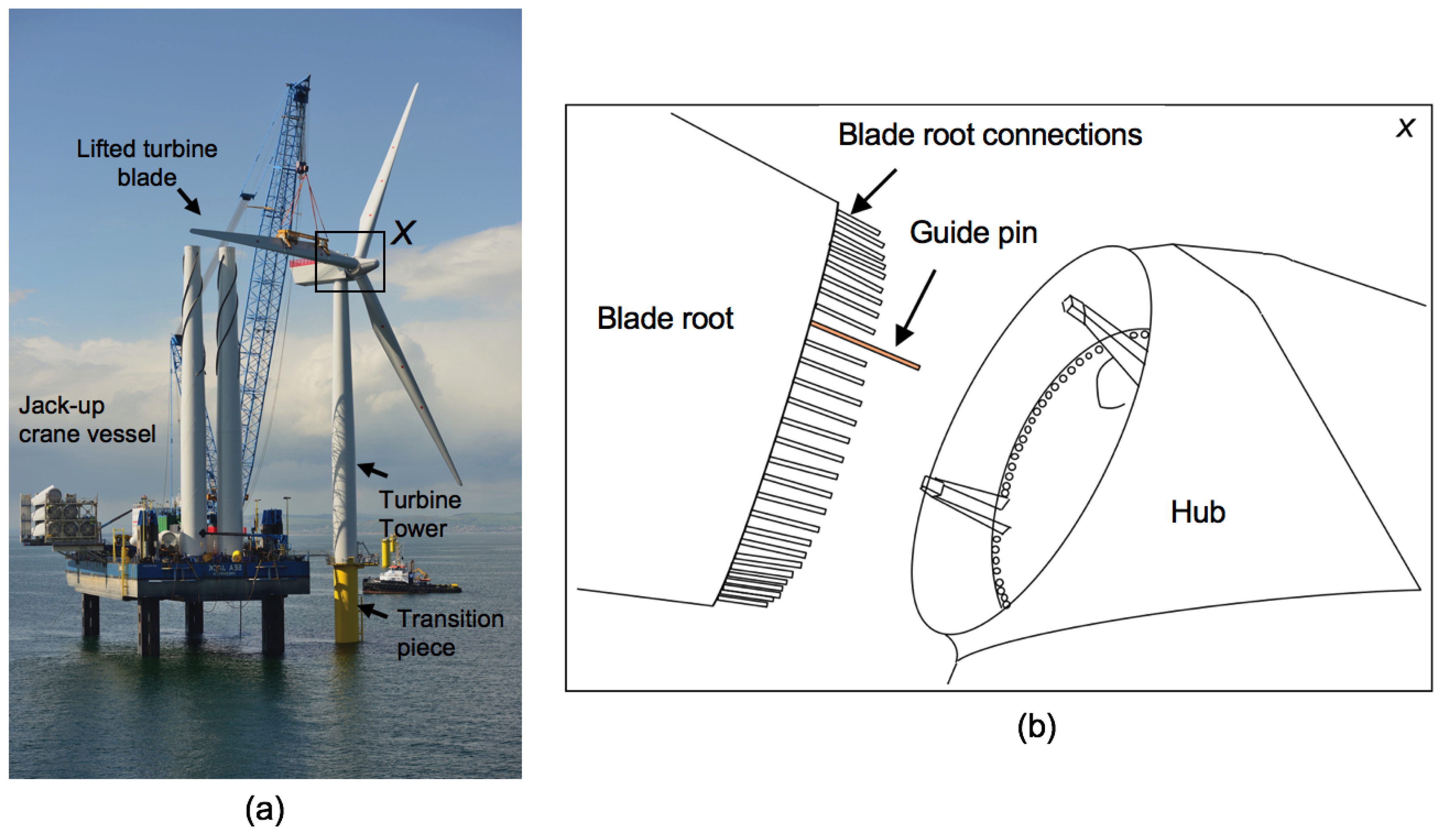
There are several methods currently employed in the industry for OWT installation, where a split installation procedure is preferred for installing monopile-type OWTs [5,24]. Here, the components of turbines are stacked and shipped in disconnected pieces to the offshore site and are individually assembled offshore. This method is favored as it offers effective deck space area use, and thus the overall transportation time is reduced. During the single-blade installation, the individual blades are lifted piece-by-piece (i.e., three lifts per turbine) from the vessel deck and are made to mate with the hub. A jack-up crane vessel is usually used because of their legs which are anchored into the seabed (Figure 2a), while the blade is being lifted, and thus provides stability. Nevertheless, wind-turbine blade-mating process, is still a highly demanding task and requires a substantial degree of accuracy [19]. Several bolted connections are present at the blade root, and are required to be docked into the flange holes of the hub [26,27] (Figure 2b). The challenge to the mating operation is due to the considerable relative motions between the blade root and hub which can cause impact loads at the sensitive root connections. The relative motions are caused due to joint result of wind-generated blade-root responses and wave-generated monopile vibrations [24].
A wind-turbine blade is an aerodynamically designed structure and is sensitive to wind induced loads during lifting, the effects of which are critical at tower-top heights spanning more than 100 m. This causes pendulum type oscillation motion at the blade root during mating. Furthermore, the monopile foundation structures are sensitive to wave-induced loads, and have limited damping attributes, especially in the absence of aerodynamic damping from blades. The overall damping of the monopile structure is close to 1% [30]. Due to the relatively small damping level, resonance induced substantial tower-top hub motions are developed while performing the mating task in wave periods close to the natural period of the monopile. Overall these relative motions can cause impact loads at the blade root due to impact with the hub, and can damage the sensitive root connections [19,26]. Such events are critical from the structural viewpoint, as the root of the blade takes maximum flapwise and edgewise bending loads [31], and therefore any damage during the installation phase can negatively affect the structural integrity, jeopardizing the installation task [26]. Overall, the associated risks and high consequences make the estimation of response based on operational sea state for blade-mating process a topic of substantial engineering interest to the industry.
Attempts have been made in the literature to understand the responses developed during the blade-root mating process. Jiang et al. [24], developed a detailed numerical model in HAWC2 [32] for assessing dynamic response in the installation system during mating phase. The relative motion between hub and blade was found substantial and was thus analyzed for various wave and wind conditions based on the NREL 5 MW blade [33]. Jiang et al. [30], Verma et al. [27] also suggested an application of tuned mass damper in the hub during installation, which can damp out excessive hub motions, thus reducing the relative motion. Verma et al. [19] studied the impact investigation of blade root with the hub using detailed finite element analysis. In view of the nature of the damages assessed due to such events, post impact on-board decision was recommended. Ren et al. [34,35] developed an open access simulator for OWT blade installation in Simulink/MATLAB. Wang et al. [36] used computational fluid dynamics (CFD) codes to analyze the wind forces on wind-turbine blades during lifting. Gauna et al. [37,38] used the cross-flow principle, a simplification over computationally costly CFD code to analyze the wind forces on the blade, and later tuned the model for DTU 10 MW blade [39]. Kukijen et al. [40] used the HAWC2 code and CFD code to analyze the blade responses during mating. Zhao et al. [41] developed a SIMO-Aero tool for analyzing blade responses during installation.
Currently, a common practice in the industry is to use only the allowable mean wind speed ( U w ) as the limiting criteria for the blade-mating task [25]. However, it is studied in [24,42] that the mating process is equally sensitive to H s , T p and the degree of wave-wind misalignments ( β w a v e ), and hence these parameters must be included in the assessment. In this paper, we derive the limiting sea states for the mating task considering all these parameters ( H s , T p , U w , β w a v e ) which will be discussed in the subsequent sections. Firstly, a description of the installation procedure for the blade-mating task is described below. Furthermore, the critical events and impact scenarios which are likely to occur during the mating phase are discussed.

2.1. Procedure

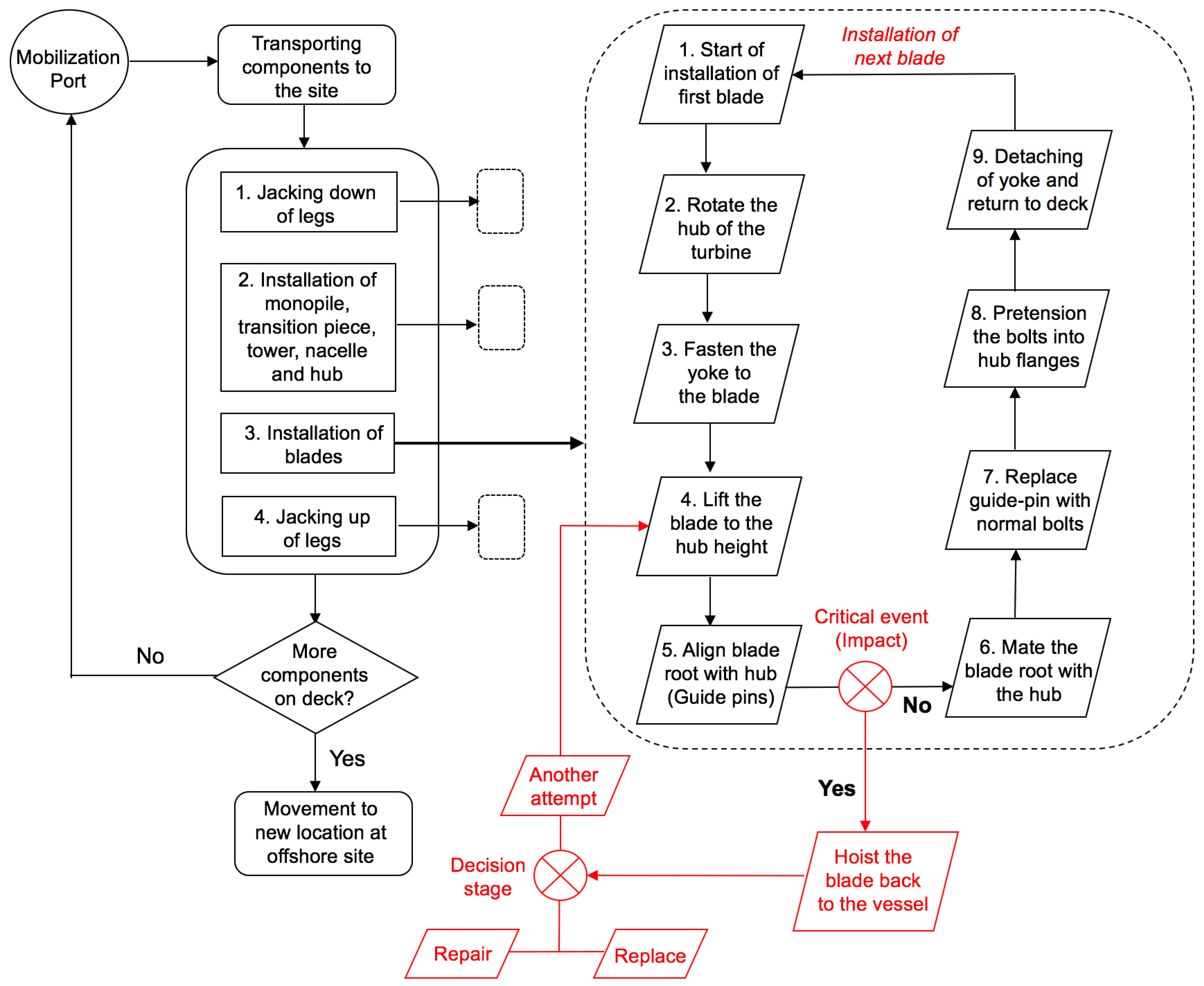
A generic installation procedure for mating OWT blades onto a preassembled hub is presented in Figure 3. The wind-turbine blade installation phase commences after the prerequisite tasks such as transportation of turbine components from port to site, jacking down of legs, and installation of components such as monopile, transition piece, tower, nacelle, and hubs are completed. Each task has its own set of detailed procedures; however, in this article, we focus explicitly on mating phase of wind-turbine blade and their stepwise procedure is described in black dotted box in Figure 3. First, the preassembled hub of the turbine is rotated using special equipment for horizontal alignment between root and hub. Then the yoke of the crane is attached to the blade and the yoke-blade system is lifted to the hub height. Please note that the guide pins, which are long sized bolts [19], are inserted in the blade root before the blade is lifted. These bolts enable the visual monitoring of the mating process as the offshore banksman in the hub carefully tracks its motion with respect to the flange holes during the mating. Once the guide pin is successfully docked into the flange hole, the blade root is finally mated into the hub. After the successful docking operation, the offshore crew replaces the guide pins with normal size bolts. All the bolts are then pretensioned into the hub [43], while the yoke of the crane system is detached from the blade and is lifted back to the vessel. This whole sequence of activities is repeated for the next blade and is continuous until all the three blades are installed for a turbine.

2.2. Critical Event and Limiting Response Parameter

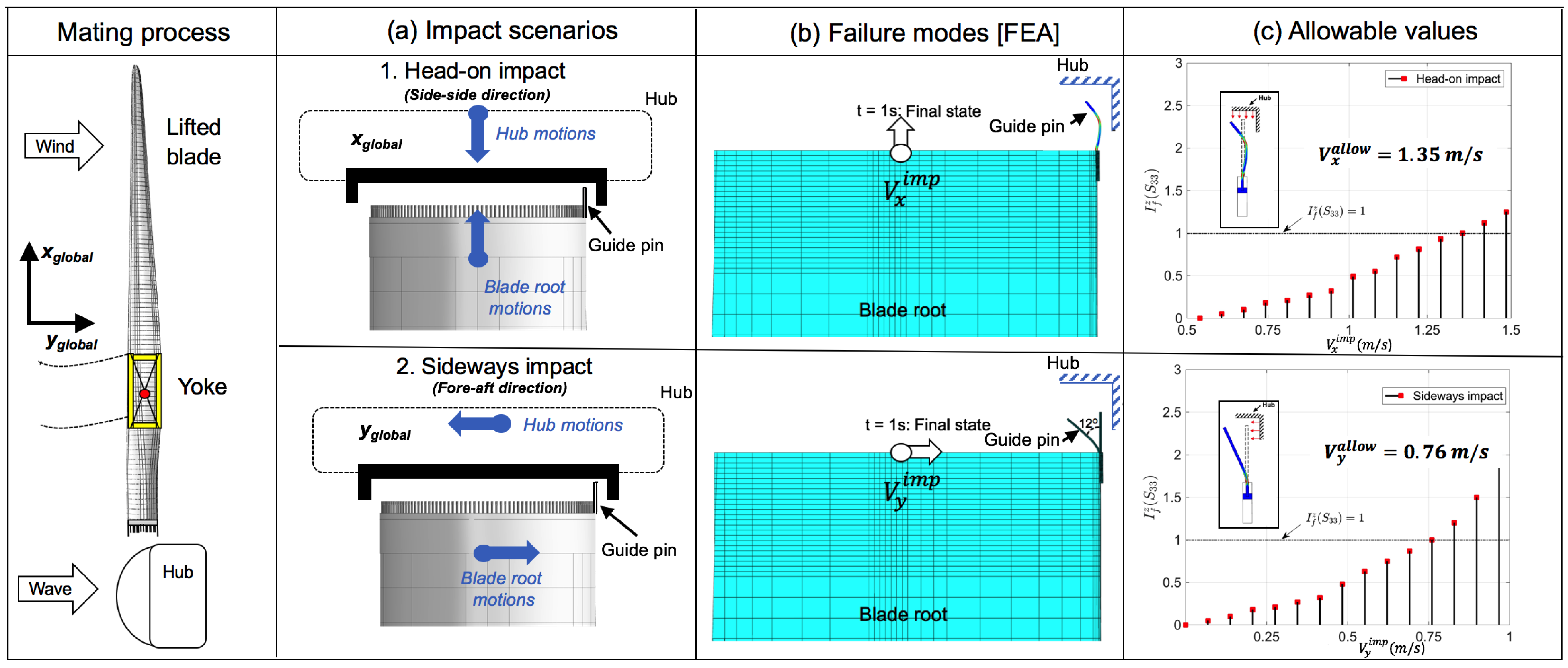
A critical event that has the potential to cause the failure of the tasks is the risk of impact between guide pin and hub through the process of mating [19,25]. The limiting response parameter which decides the criticality of such events are the impact velocities amid these components in global x and y directions ( V x i m p , V y i m p ) [42]. It is to be noted that in practice, there could be different critical events and corresponding list of response parameters that will govern the safety of the installation task. For instance, this may include stress in the crane and crane foundation, tension in the lift wire and tugger lines. In this study, we consider the damages in the blade root the most critical event based on industrial interactions where the occurrence rate of such events are frequent and are reported between 1 in 10 operations to 1 in every 100 operations [25].
There were two distinct impact scenarios identified in the previous work [19] (Figure 4), depending upon the effects of wind–wave misalignments and global relative responses of the installation system. Head-on impacts between blade-root guide pin and hub (Figure 4a) occur because of the misalignment between wind and waves during mating, where relative responses are dominant in the side-side direction (global x-direction). On the other hand, sideways impact scenarios (Figure 4a) between blade-root guide pin and hub mainly occur due to aligned wind–wave conditions where relative responses are dominant in the fore-aft direction (global y direction). Also, detailed finite element analyses were performed in [19] based on the DTU 10 MW blade (Figure 4b), where it was found that sideways impact scenarios are more serious [42] and cause inelastic bending of guide pins, along with damages to the adjacent root laminate. On the other hand, a head-on impact scenario is less critical and causes s-shape buckling of the guide pin at relatively higher impact velocities (see Figure 4b). Furthermore, the allowable impact velocities for both the scenarios were obtained which were 0.76 m/s for sideways impact and 1.35 m/s for head-on impact (Figure 4c). It is to be emphasized that due to such critical event of impact during mating, the hoisted blade is required to be brought back to the vessel, where a decision is taken about the blade requiring repair, replacement or possibility of another mating trial (see Figure 3). In [19], a systematic procedure based on damages at the blade root was discussed to guide the offshore crew in making such post impact decisions. In this paper, we use these parameters to obtain limiting sea states for planning of such tasks so that these events can be prevented. The next section describes the proposed response-based methodology for blade-root mating task.

3. Methodology

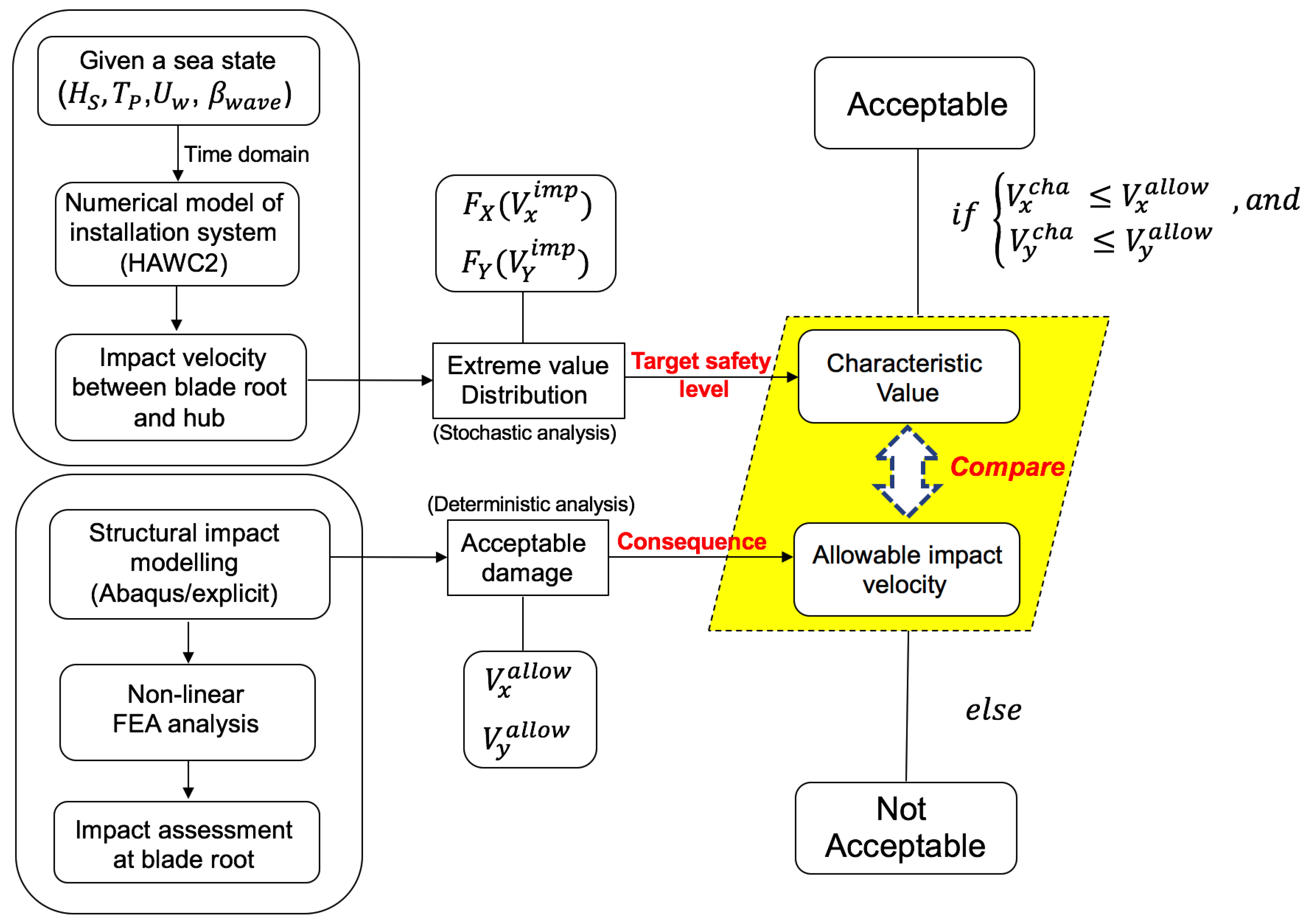
Figure 5 presents the response-based methodology for estimating limiting sea states for blade-root mating tasks. The methodology is comprised of three related steps which are described below:
(1) Global response assessment of the mating system: Here, the installation system characterizing the mating process is numerically modelled using multibody simulations. Software from SIMO [44], HAWC2 [32], Ren et al. [34,45] etc. can be used. Time-domain stochastic analyses for various sea states, characterized by different combinations of H s , T p , U w , β w a v e is performed. Furthermore, response statistics for limiting response parameters ( V x i m p , V y i m p ) are analyzed and extreme value distributions ( F V x ( V x i m p ) and F V y ( V y i m p ) ) are derived for each sea state and for reference duration of the mating task which is considered to be 10 min. Finally, a characteristic value ( V x c h a , V y c h a ) for a target probability of exceedance is evaluated for each sea state. Please note that in this study, 10 2 exceedance level is considered, and it corresponds to practical reported incident data in the industry [25] including an acceptable consequence level for the installation task in case of such an event. The categorization of different safety levels and corresponding consequences can be found in [26], and is also discussed briefly in Section 6.5 of this paper.
(2) Impact analysis of the blade root with the hub: Here, finite element method (FEM) is used to investigate damages developed at the root connection because of impact with the hub. Standard FEM solvers such as Abaqus [46], Ansys [47], or other user defined solvers with explicit or implicit integration scheme can be used. Both impact scenarios are numerically modelled, and allowable levels of impact velocities in x and y direction ( V x a l l o w , V y a l l o w ) are established. These values correspond to the threshold level of impact velocity below which there are no damages in the composite root laminate [26]. These values were already determined in the previous work [19,42] and were reported in Figure 4.
(3) Assessment of allowable sea states: In the final step, the characteristic values of impact velocities ( V x c h a , V y c h a ) obtained in step 1 for different sea states are compared individually with the allowable impact velocities ( V x a l l o w , V y a l l o w ) obtained from finite element analysis in step 2. The sea states in which the characteristic values in both the impact scenarios are less than the allowable responses are considered acceptable for the mating task, otherwise the sea states are not acceptable. Therefore, the overall criteria for estimating allowable sea states in this study is given by:
( : x X ) ; i f V x c h a V x a l l o w V y c h a V y a l l o w , t h e n the sea state ( x ) is acceptable , e l s e not acceptable
where X is a set of all sea state x for which the response analyses of the installation systems are performed.

4. Modelling of Installation System

A case study is presented in this paper based on mating process of DTU 10 MW blade [39], hence the parameters used in the modelling correspond to DTU 10 MW reference wind-turbines. The installation system is modelled in HAWC2 [32] numerical analysis code from DTU and consists of two sub-systems: (1) monopile sub-system; and (2) blade-lift sub-system. The modelling process is described in detail in the previous study [19], and therefore a brief description is presented below.

4.1. Preassembled Monopile Sub-System

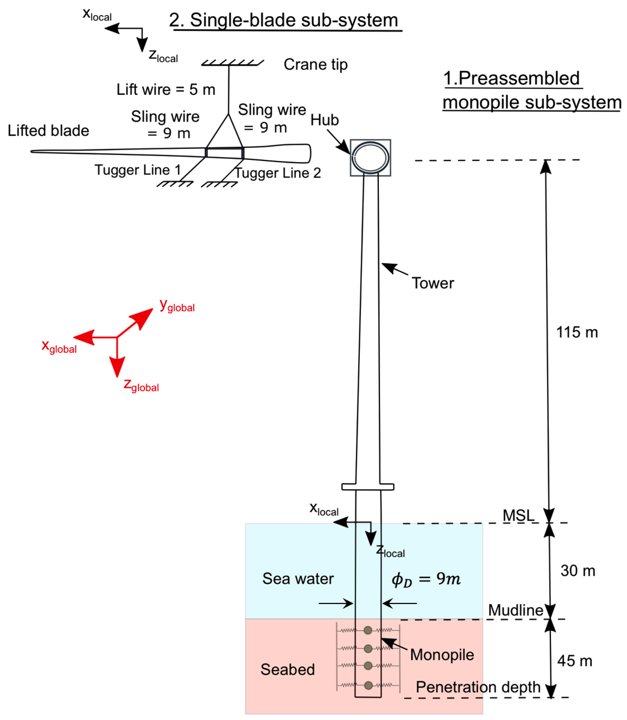
This sub-system includes monopile, tower, nacelle, and three hubs (Figure 6). The developed model has the capacity of calculating wave-induced hydrodynamic effects on the monopile, aerodynamic effects on the tower, as well as considers the pile–soil interaction. The wave-induced hydrodynamic effects on the monopile are estimated based on Morison equation [48], which consists of drag as well as inertia terms for slender structures. The monopile support structure used in the modelling is obtained from the work of [49], where design support structure was studied for the DTU 10 MW wind-turbine. The model considers uniform sand layer as the characteristic soil for the monopile, and the non-linear p y curves (for lateral stiffness) were obtained from finite element analysis. The parameters of the other components of the sub-system i.e., tower, nacelle, and hubs are of the DTU 10 MW wind turbine and are also tabulated in Table 1. The damping ratio of the monopile in their characteristic first fore-aft and side-side modes were assigned a value of roughly 1%, and is based on the previous studies on the monopile structure [50,51]. The important characteristics of this sub-system such as monopile diameter ( ϕ D ), tower height, pile penetration depth and water depth are also illustrated in Figure 6.

4.2. Single Blade-Lift Sub-System

The second sub-system contains a 10-MW blade [39] with realistic yoke and tugger line properties. The wind-turbine blade leading edge is considered to be oriented parallel to the wind direction. Two tugger lines are used to constrain the motion of blade in their horizontal plane; and are attached equidistant from the blade’s center of gravity. An eigen frequency analysis is performed to obtain the natural periods of the system. The modelled sub-system can calculate aerodynamic loads on the wind-turbine blade, where Mann’s turbulence [52] box from HAWC2 is used. Steady aerodynamic coefficients are used, and effects of dynamic stalls are neglected. Furthermore, cross-flow principles are considered which neglect the wind flow along the span of the blade. The important characteristics of this sub-system such as length of the lift wire, sling wires, and position of the tugger lines are illustrated in Figure 6.

5. Environmental Conditions

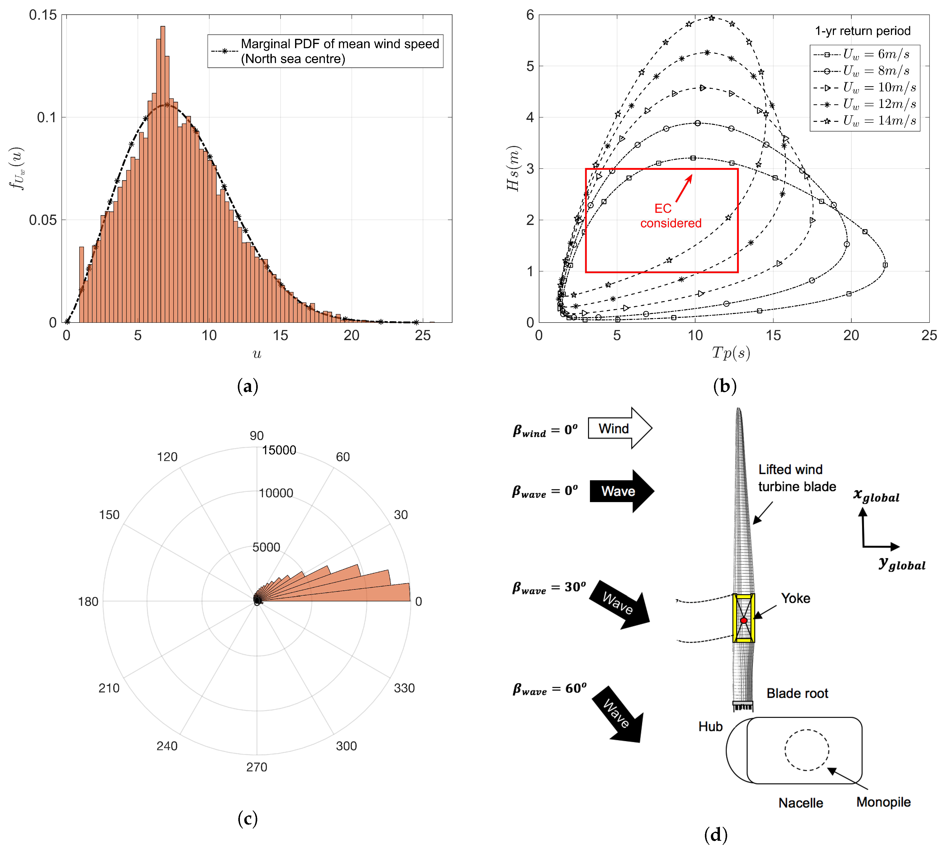
In this study, North Sea center is taken as a representative offshore site for wind-turbine blade-mating task. The characteristic water depth of site is recorded as 29 m [53] and closely resembles the water depth considered for the modelling of installation system. Figure 7a presents the marginal PDF of mean wind speed ( f U w ( u ) ), along with its normalized histogram from 10 years of hindcast data at the offshore site. It can be clearly seen that the site has a mean wind speed ( U w ) of 4–16 m/s as dominant. In this work, a practical range of mean wind speed ranging between 6 to 14 m/s is considered for the time-domain analysis (at a bin width of 2 m/s i.e., 6:2:14 m/s); see Table 2. Furthermore, the 2D-contour surface for H s - T p and different ranges of wind speeds and corresponding to 1-year return period for the chosen offshore site is also presented in Figure 7. The red rectangular box represents the boundary of H s and T p combinations considered in this study for the analysis. H s is considered at a bin width of 0.5 m (1:0.5:3 m), whereas T p is considered at a bin width of 2 s (4:2:12 s) for time-domain analysis; see Table 2. The reason for restricting the analysis domain within H s 3 m, is because any load case with H s > 3 m is expected to cause unacceptable dynamic responses for the mating task. Finally, the hindcast data at the offshore site also shows that the site has wind–wave misalignments ( β w a v e ) varying between 0° to 60° (see Figure 7c), and thus for each combination of H s , T p and U w , three cases of wind–wave misalignments are considered. Figure 7d presents a bird view of the blade-root mating task and different cases of wind–wave misalignments considered along with definitions of global coordinate systems. Furthermore, for each case mentioned in Table 2, there were 20 seeds considered for estimating response statistics, with each seed total duration being 1000 s. Also, during the data analysis, the first 400 s from each time series are removed to avoid any start-up effects. Overall, a total of 7500 (375 × 20) different load cases were considered for the time-domain analyses in this study.

6. Results and Discussion

In this section, important response parameters such as hub motions, displacement of blade root, and impact velocities amid root and hub are described first. The response statistics are defined in terms of their response-time series, spectral density curves, as well as the comparison of their standard deviations for important load cases with varying wind–wave misalignments. Then, based on the proposed methodology, extreme value analysis of the limiting response parameter is performed, and the limiting sea state curves for the blade-root mating task are determined.

6.1. Hub Motions

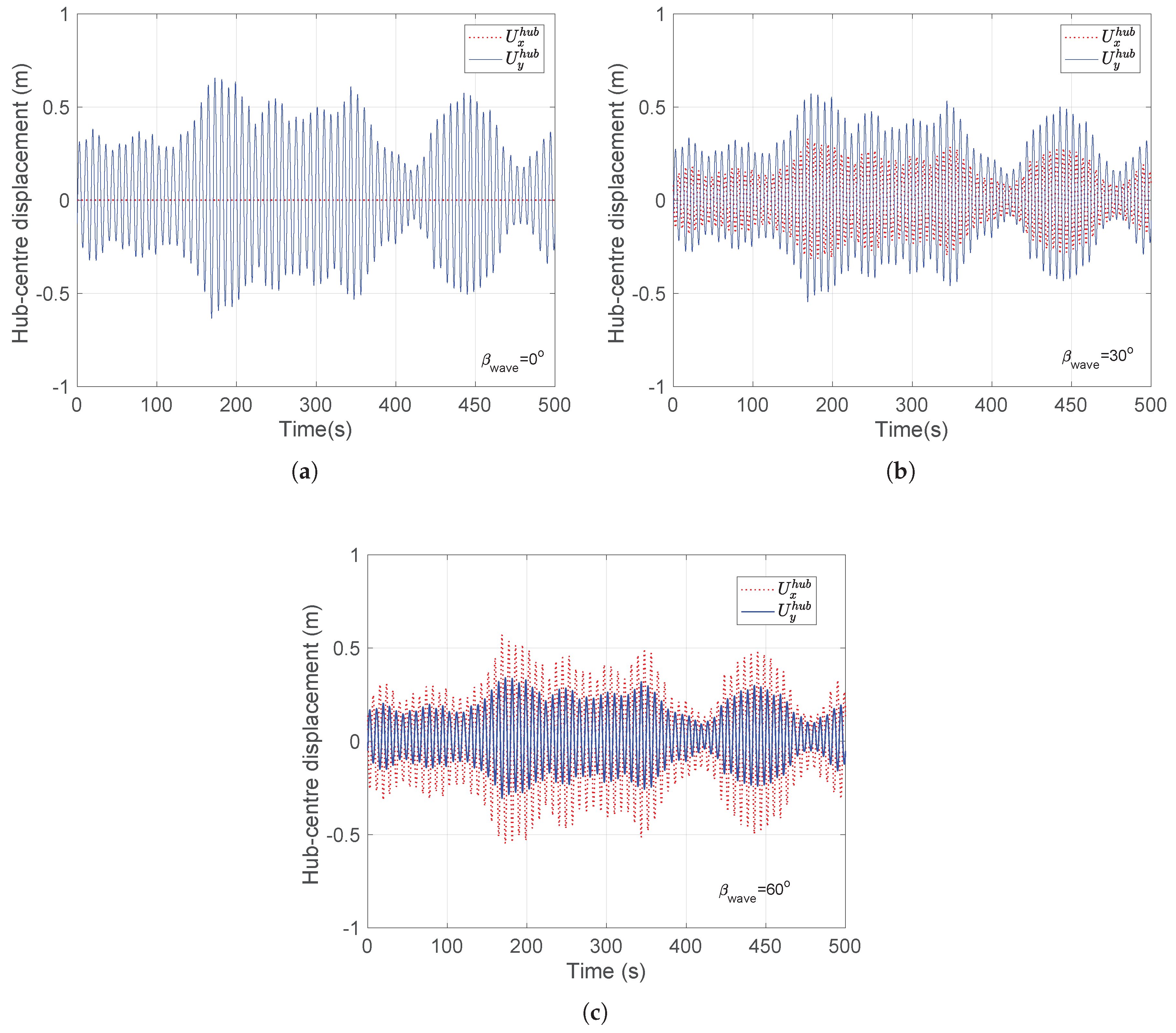
Figure 8a–c compare the hub-center displacement in the side-side and fore-aft directions ( U x h u b , U y h u b ) for mating operation in the environmental conditions corresponding to H s = 2 m, U w = 8 m/s, T p = 4 s and three different β w a v e = 0 °, 30°, 60° respectively. It can be clearly seen that for β w a v e = 0 °, the hub-center responses is dominant in the fore-aft direction, whereas there are no hub-center responses in side-side direction. On the other hand, it can be seen that with increase in wind–wave misalignment ( β w a v e ), there is a gradual increase in the motion of hub-center in the side-side direction, and this response dominates for β w a v e = 60 ° (see Figure 8c). Please note that this characteristic of the hub motion response influences the impact scenarios for the blade-root impact with hub during the mating process. For instance, as already discussed previously, the sideways impact of the guide pin with hub is caused by dominant responses in the fore-aft direction (global y direction), and this makes aligned wind–wave conditions hazardous ( β w a v e = 0 °) during mating operations.
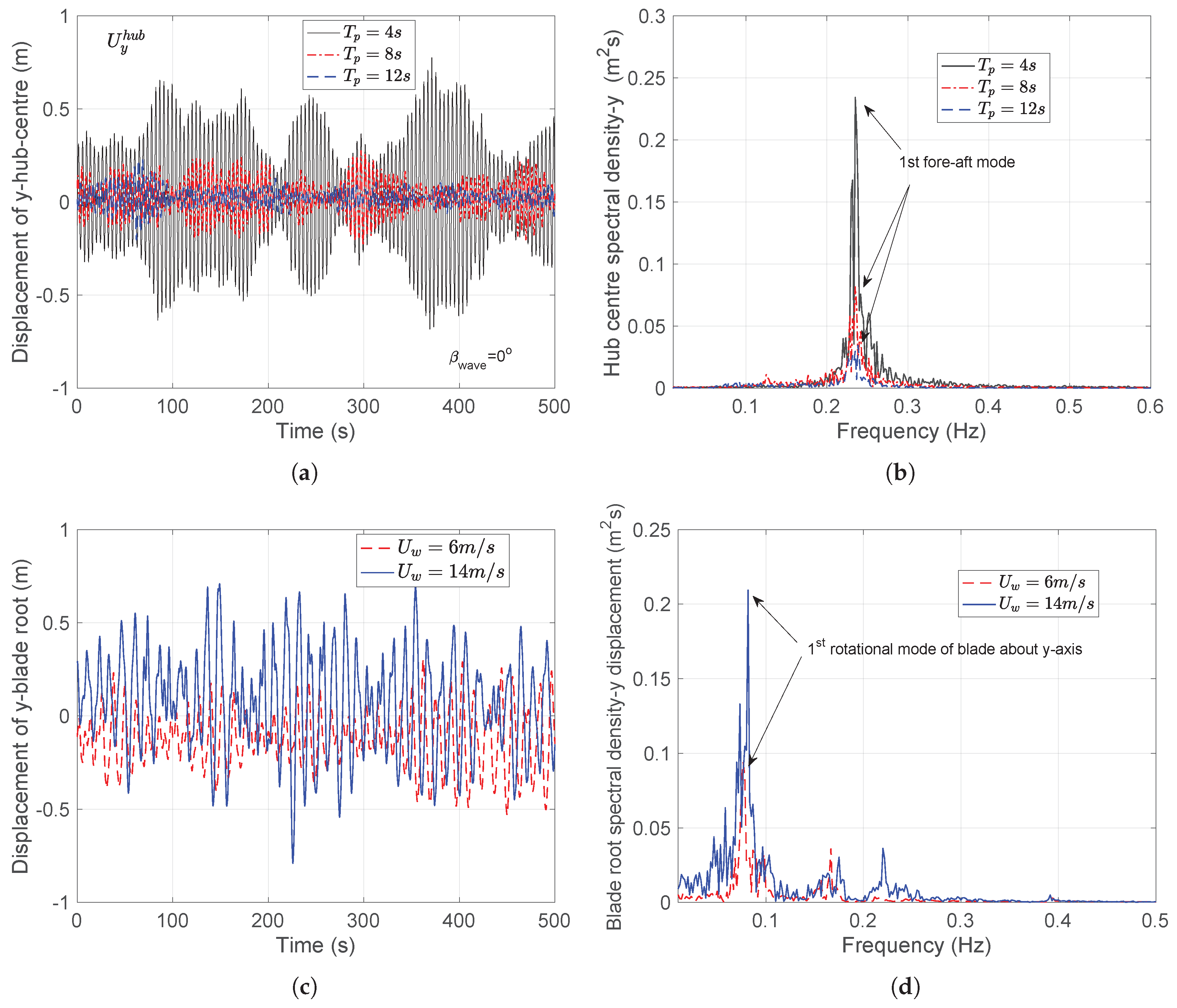
Figure 9a compares the displacement of the hub-center in the critical fore-aft direction ( U y h u b ) for mating operation in the environmental conditions corresponding to H s = 2 m, U w = 8 m/s and for different T p = 4 s, 8 s, and 12 s. It can be clearly seen that the motion of the hub-center is dominant for T p = 4 s, and reduces with further increase in T p . This is due to the fact that the monopile has a natural period of 4.2 s in the first fore-aft mode, and thus develops resonance induced response in an environmental condition with T p = 4 s. On the other hand, environmental conditions with T p = 8 s, and T p = 12 s, are distant from the resonance frequency of the monopile structure, and thus the responses developed in the hub-center are less. This is also shown in Figure 9b, where the spectral density curve for U y h u b , obtained using the Fast Fourier Transformation (FFT), is compared for T p = 4 s, 8 s, and 12 s. The peak frequency (0.24 Hz) corresponding to the first fore-aft mode of the monopile is highest at T p = 4 s, whereas it reduces with T p advancing far from the excitation frequency. It is to be noted that the monopile structure has a deficient damping characteristic with damping ratio close to 1% critical. This attribute is even acute during the mating process, as the aerodynamic damping from the blades towards the monopile are non-existent during installation.

6.2. Blade-Root Motions

Figure 9c compares the displacement of blade root in the fore-aft direction (y) for mating operation in an environmental condition corresponding to H s = 2 m, T p = 8 s and for two different U w (6 m/s, 14 m/s). As expected, the motion of the blade root is larger for U w = 14 m/s, compared to U w = 6 m/s. This is also shown in Figure 9d, where the spectral density curve for the motion of the blade root is compared for the above-mentioned U w . It is seen that the peak frequency corresponding to the first pendulum mode of the blade about the y-axis is highest for U w = 14 m/s. Please note that the blade-root responses in x-direction is negligible because of restraining action of tugger lines.

6.3. Impact Velocities between Root and Hub

There are two critical response parameters of interest for estimating response-based limiting sea states: impact velocity in the side-side direction ( V x i m p ), which causes head-on impact between blade-root guide pin and hub, and impact velocity in the fore-aft direction ( V y i m p ), which causes sideways impact between blade-root guide pin and hub. These responses are individually described below.
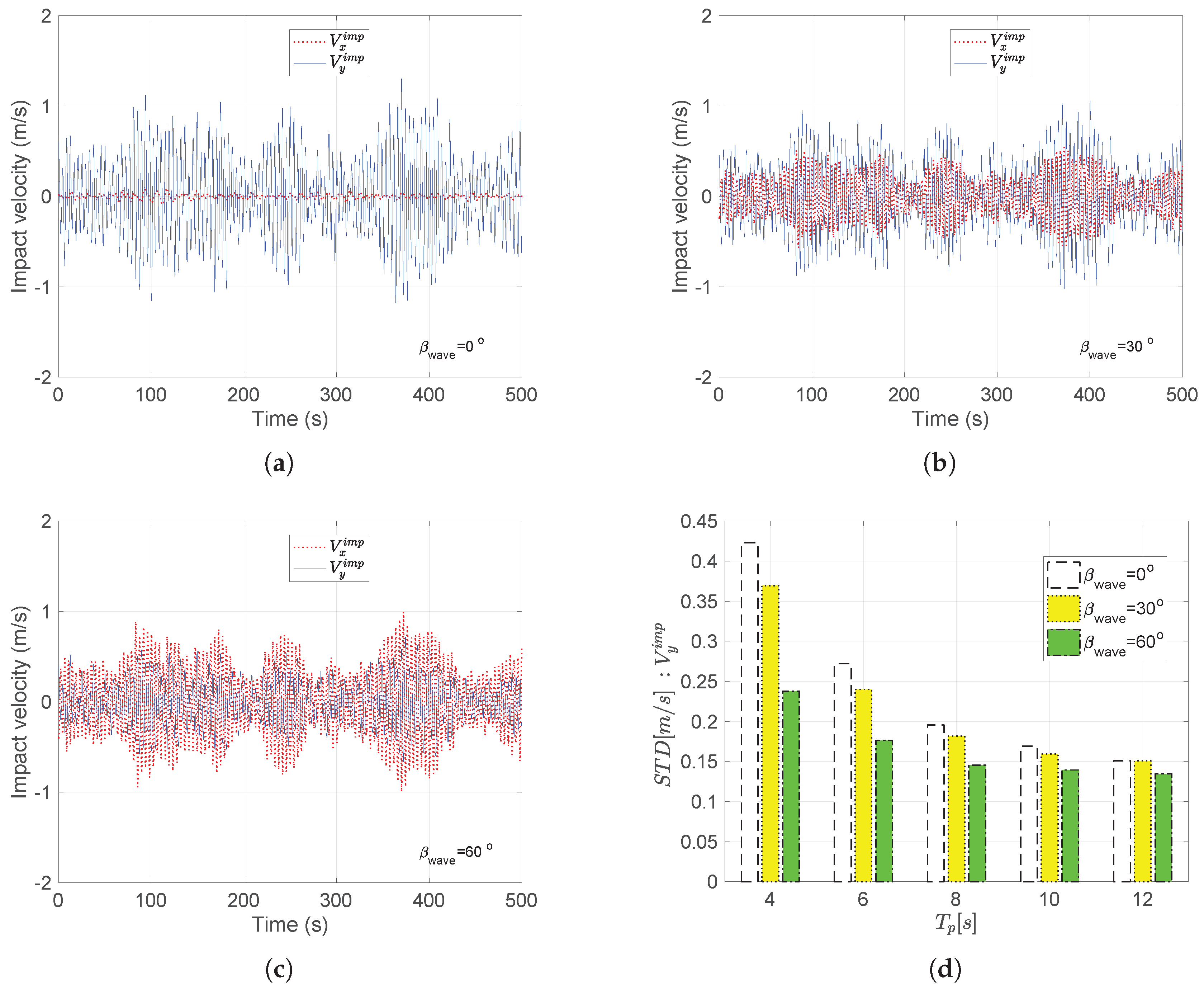
Figure 10a–c show V x i m p and V y i m p for mating operation in the environmental conditions corresponding to H s = 2 m, U w = 8 m/s, T p = 4 s and three different β w a v e = 0 °, 30°, 60° respectively. It can be clearly seen that the aligned wind–wave conditions have critical responses explicitly in the fore-aft directions, and as expected, the impact velocity in the side-side direction becomes increasingly critical for cases with increased wind–wave misalignments. It is to be also noted that the maximum value of V y i m p especially for aligned wind–wave conditions ( β w a v e = 0 °) corresponding to the given load case reaches a value more than 1 m/s, and is greater than the allowable values calculated from finite element analysis ( V y a l l o w = 0.76 m/s). Figure 10d compares the standard deviations for V y i m p for mating operation in the environmental conditions corresponding to H s = 2 m, U w = 8 m/s, β w a v e = 0 °, 30°, 60° and different T p = 4 s, 6 s, 8 s, 10 s, and 12 s. It can be seen that the standard deviations for impact velocities are highest for T p = 4 s, which is near the eigen period of the monopile structure in the first fore-aft mode. The standard deviation further reduces with increase in T p , as the values become distant from the excitation frequency of the monopile structure. Also, it is seen from the figure that for any T p , the responses are highest for aligned wind–wave conditions ( β w a v e = 0 °). For example, for T p = 4 s, the standard deviation for V y i m p at β w a v e = 0 °is 0.42, whereas for β w a v e = 60 ° the standard deviation for V y i m p is 0.24.
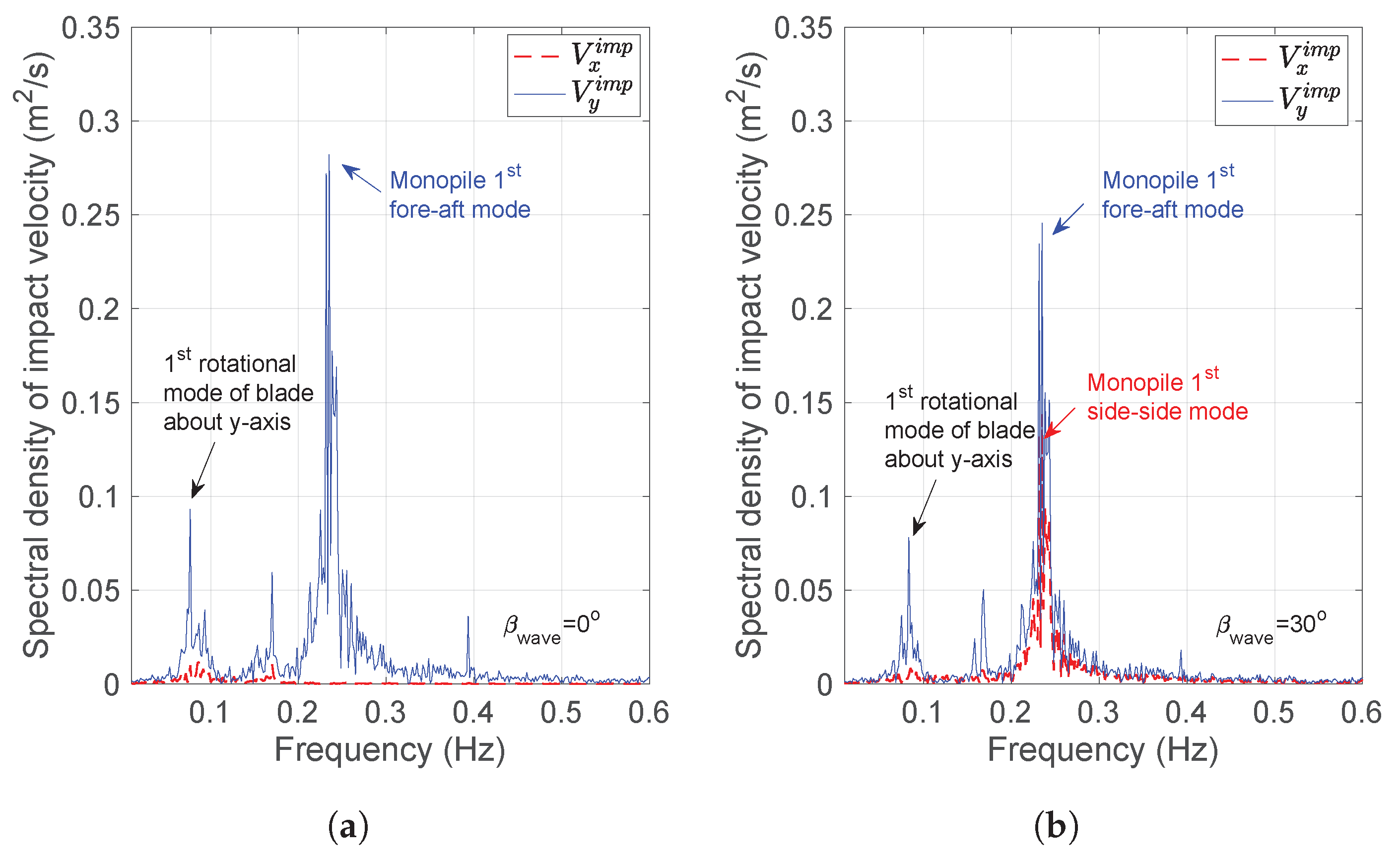
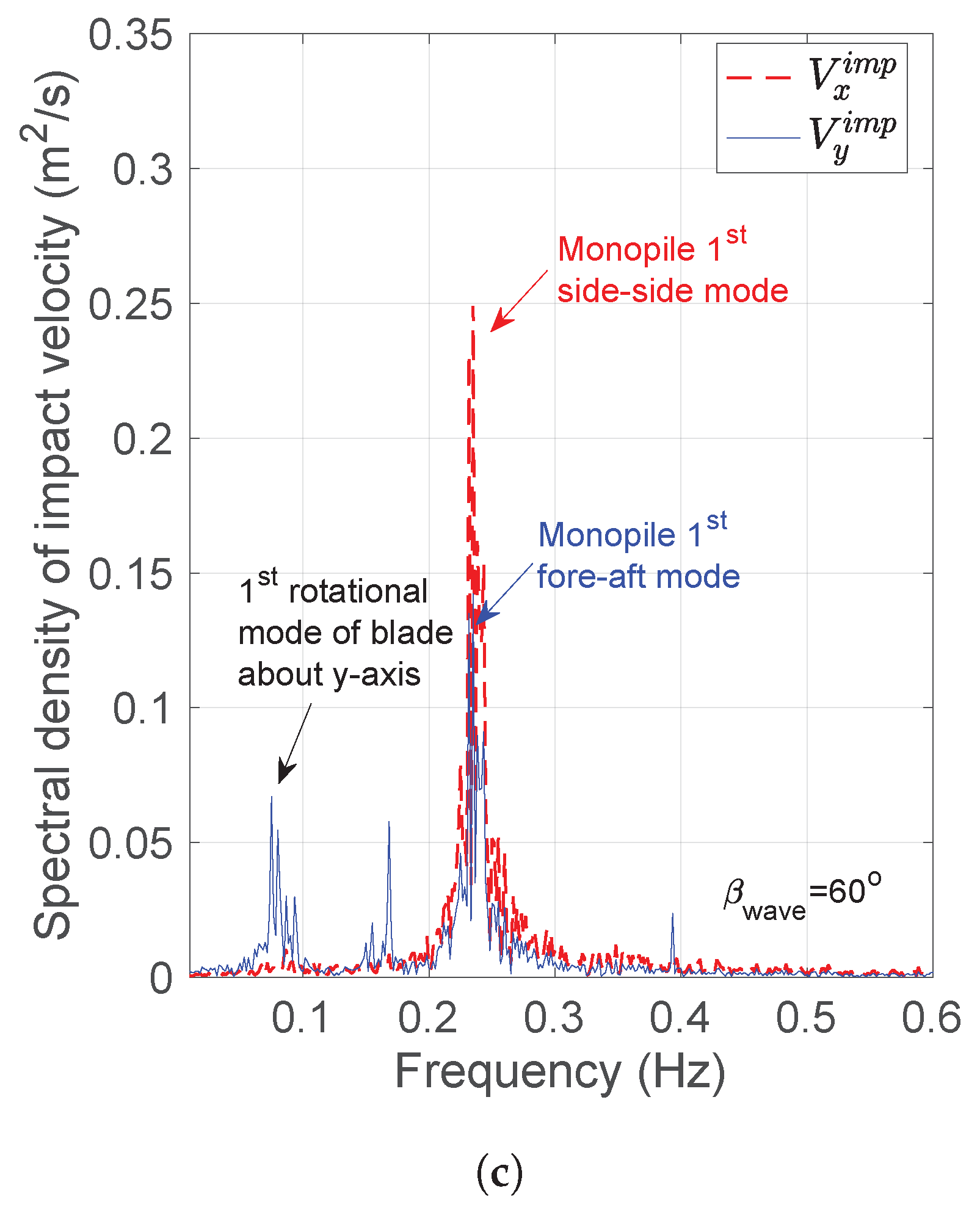
Figure 11a–c present the spectral density curves for the impact velocity in the side-side direction ( V x i m p ) and fore-aft direction ( V y i m p ) for mating operation in the environmental condition corresponding to H s = 2 m, U w = 8 m/s, T p = 4 s and three different β w a v e = 0 °, 30°, 60° respectively. In the first figure for β w a v e = 0 °, wind and wave are completely aligned in the fore-aft direction and therefore there are no peaks observed for V x i m p . However, for V y i m p , there are at least two major peaks observed in Figure 11a. The first peak corresponds to the first pendulum motion mode of the lifted blade about global y-axis which corresponds to 0.08 Hz and the second peak corresponds to the first fore-aft bending mode of the monopile which corresponds to 0.25 Hz. The spectral density peak is highest at 0.25 Hz because the mating operation is considered for the load case with T p = 4 s, and is close to the excitation frequency of the monopile structure (0.25 Hz). Therefore, significant hub motion responses caused by wave-induced monopile vibrations are developed and play a significant role in the impact velocities developed between hub and root during the mating process. This result is an improvement on the common notion in the industry where the planning of blade-root mating process is governed exclusively in terms of blade-root responses, and U w is considered alone for decision making. The contribution of hub responses clearly indicates the importance of evaluating limiting sea states not just in terms of U w (which maps blade-root responses) but also H s and T p (which maps hub motion responses). Again, for β w a v e = 30 ° due to increase in the misalignment, impact velocity in the side-side direction gradually increases and becomes dominant for β w a v e = 60 °. In summary, for all β w a v e , there are two important peaks found in the spectral density curves for V y i m p —(1) the first pendulum motion mode of the lifted blade about global y-axis which corresponds to 0.08 Hz, and (2) the first fore-aft bending mode of the monopile which is 0.25 Hz. On the other hand, for V x i m p , there are no peaks related to blade-root responses given that the wind is assumed in the fore-aft direction. There is only one peak observed at the 0.25 Hz, which corresponds to eigen frequency of the monopile in the first side-side mode. The results from the spectral density imply that the sideways impact of the blade root with hub caused by impact velocity in the fore-aft direction is dominated by both blade root and hub responses. On the other hand, head-on impact between root and hub is contributed purely by hub responses.

6.4. Extreme Value Analysis of Limiting Response Parameter

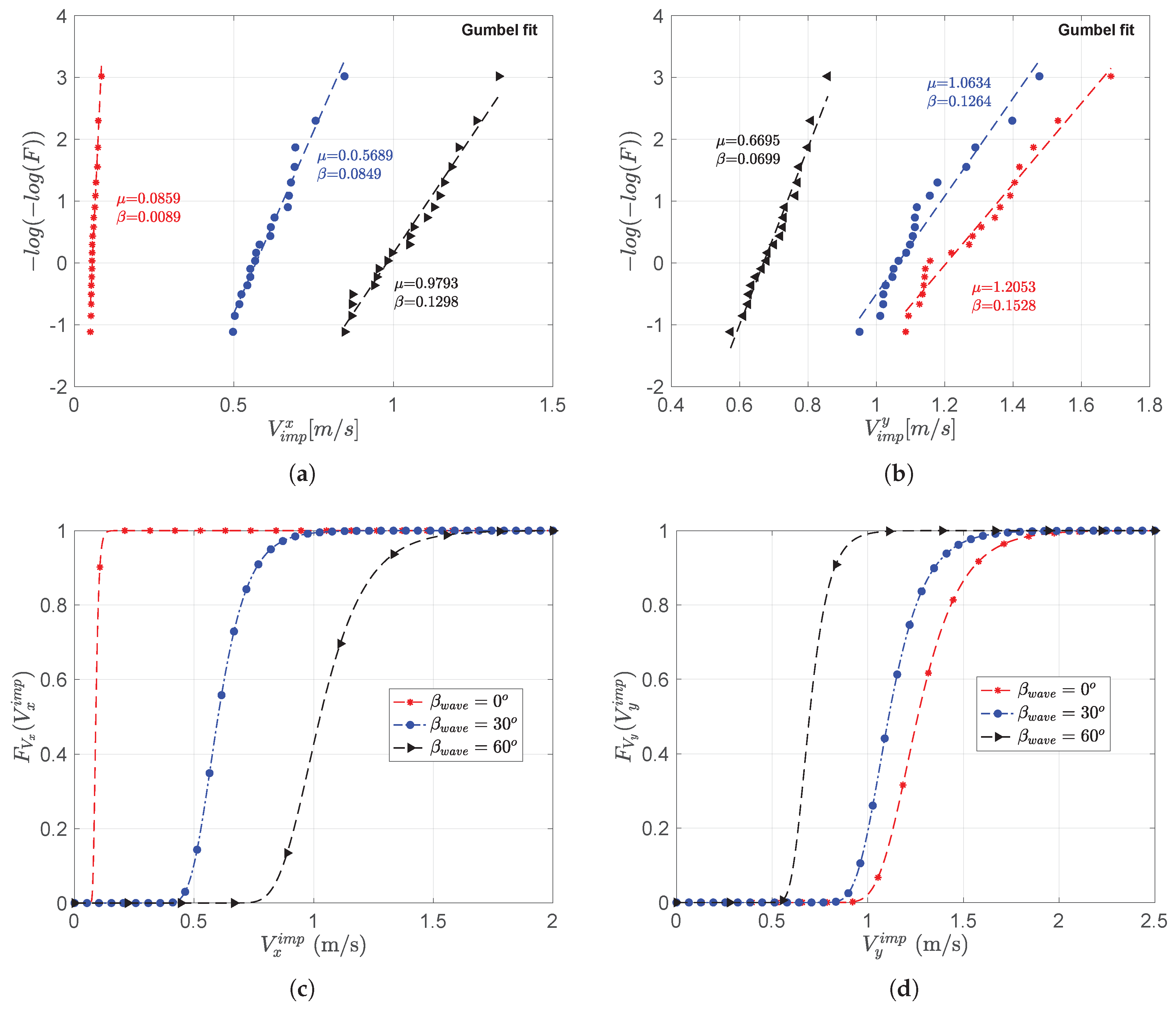
One of the most important steps in the proposed response-based methodology is to perform extreme value analysis of the limiting response parameter i.e., impact velocity in the side-side ( V x i m p ) and fore-aft directions ( V y i m p ) for different load cases. Please note that there were twenty (20) seeds considered for each load case, and therefore, maximum value from time series corresponding to each seed is obtained and fitted to Gumbel probability paper. Figure 12a,b show the fitting of maximum values of V x i m p and V y i m p to the Gumbel probability paper for load case H s = 2 m, U w = 8 m/s, T p = 4 s and three different β w a v e = 0 °, 30°, 60° respectively. It can be clearly seen from the figure that the data fitted the Gumbel probability paper quite satisfactorily. A chi-squared ( χ 2 ) goodness-of-fit hypothesis test for Gumbel cumulative distribution function is also performed and null hypothesis ( H o : data is represented by Gumbel distribution) was found to have been not rejected at the selected significance level of 5% (0.05). Therefore, it was confirmed that the Gumbel distributions fitted the data sufficiently well. The parameters of the Gumbel distributions were obtained for these load cases and are also explicitly marked in Figure 12a,b, next to the fitted line. Based on the estimated parameters of the Gumbel distributions, Figure 12c,d present the CDF of V x i m p and V y i m p which has the form F ( V y , x i m p ) = e x p ( e x p ( ( V y , x i m p μ ) / β ) ) , where μ and β are location and shape parameters respectively. An important characteristics of the distribution curves can be pointed out that for β w a v e = 60 °, the distribution for V x i m p lies on the extreme right side, whereas for β w a v e = 0 °, the distribution for V y i m p lies on the extreme right side.
Please note that the above discussion is made explicitly for three load cases with different wind–wave misalignment, and similar procedure including: (1) fitting of data to Gumbel probability paper (2) parameter estimation, and (3) hypothesis testing is performed for all 375 different environmental conditions considered in this study. A response surface method (RSM) is used to obtain analytical relationship between Gumbel parameters ( μ and β ) for impact velocities and different combinations of sea state parameters ( H s , T p , U w , and β w a v e ). The RSM [54] is a collection of several statistical techniques where an analytical relationship can be established for a response variable which is dependent upon multiple independent variables. Figure 13a–c present the 2D-response surface contour of μ y i m p , which corresponds to the location parameter for Gumbel distribution representing V y i m p for different H s , T p , U w = 6 m/s, and three different β w a v e = 0 °, 30°, 60° respectively. Please note that different response surface models were used, and quartic response surface model gave the best fit for the obtained data. It can be clearly seen that for all the cases, T p = 4–6 s, are critical for impact velocities because of their close proximity to the excitation frequency of monopile structures in the first fore-aft mode. Furthermore, the shape parameters for V y i m p is highest for aligned wind–wave conditions ( β w a v e = 0 °), and reduces with an increase in wind–wave misalignment. Similar argument is also made for β y i m p (see Figure 13d,e), which corresponds to the shape parameter for Gumbel distribution representing V y i m p . In this way, the Gumbel parameters for all the environmental cases were obtained and were related with sea state parameters using RSM. Please note that such a curve enables industrial practitioner and engineers to choose Gumbel parameters during planning of their installation task.

6.5. Characteristic Extreme Responses and Determination of Limiting Sea States

The final step in the proposed response-based methodology is to obtain for each load case, a characteristic extreme response ( V x c h a r , V y c h a r ) corresponding to the target exceedance probability, and then compare it with allowable values ( V x a l l o w , V y a l l o w ). The sea states in which the characteristic values in both the impact scenarios are less than the allowable responses are considered acceptable for the mating task, otherwise the sea states are not acceptable. It is to be noted that the target exceedance probability is chosen based on the type of installation tasks, and consequence of the failure events. For instance, DNV-GL [55] argues to choose target exceedance probability for the failure of lifting wire during installation task as 10 4 , given that such events are catastrophic and must be avoided. In this study, a target exceedance probability of 10 2 is considered which corresponds to 1 failure per 100 operations. This value corresponds to the consequences level where there are no damages developed in the blade-root laminate, and the blade is permissible for a second trial of the mating process in case of an impact. Please note that different ranges of target exceedance probability and their consequences using FEA were discussed and prescribed in the previous study [26]. Also, the allowable impact velocities ( V x a l l o w = 1.35 m/s, V y a l l o w = 0.76 m/s) considered in this work correspond to the analysis performed on DTU 10 MW blade. These values can also be improved by designing the installation system more efficiently, such as improving the structural property of the guide pin prone to impact, and application of crashworthiness devices etc.
Figure 14a,b present the estimation of characteristic impact velocities ( V x c h a r , V y c h a r ) corresponding to the load case H s = 2 m, U w = 8 m/s, T p = 4 s and three different β w a v e = 0 °, 30°, 60° respectively. These values are estimated based on the Gumbel parameters obtained from extreme value analyses and are extrapolated to obtain different exceedance levels. The characteristic values correspond to the point where the black dotted line at 10 2 exceedance probability intersect the curves. Please note that at the point, where the lines intersect the curves, red and green dots are marked. The green color dot represents that the characteristic values are lesser than the allowable levels, whereas red dots represent that the characteristic values are greater than the allowable levels. The sea states in which the characteristic values in both the impact scenarios are less than the allowable responses are considered acceptable for the mating task, otherwise the sea states are not acceptable (i.e., both V x c h a r and V y c h a r must be marked with green dots). For example, Figure 14a,b clearly show that for T p = 4 s, and β w a v e = 0 °, both V x c h a r and V y c h a r are greater than the corresponding allowable levels (marked with red dots) and thus the considered sea state is not acceptable for the mating task. Similarly, for T p = 4 s, and β w a v e = 0 °, 30°, although the V x c h a r is marked with green dots, V y c h a r is greater than allowable responses (marked with red dot), and thus the considered sea state is not acceptable for the mating task. On the other hand, Figure 14c,d present the V x c h a r , V y c h a r for mating operation with similar load case but with T p = 12 s. It can be clearly seen that both V x c h a r and V y c h a r are marked with green dots, and thus these sea states satisfy for the mating task. Please note that similar investigation is performed for the 375 environmental cases.
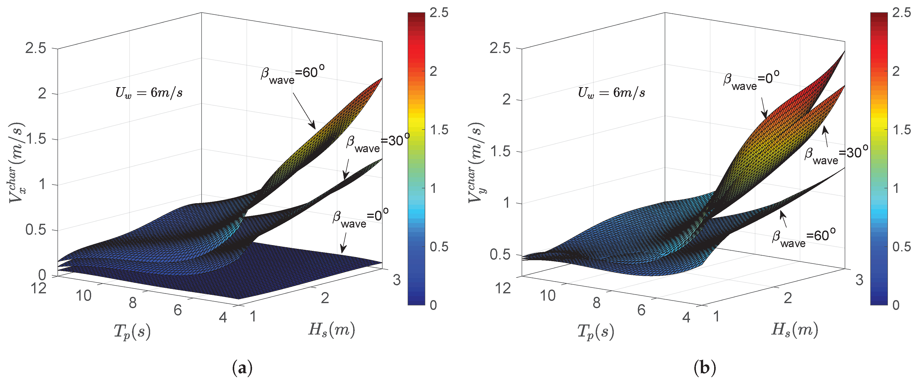
Figure 15a,b compare the response surface for V x c h a r and V y c h a r obtained for different combinations of load cases with different wind–wave misalignments ( β w a v e = 0 °, 30°, 60°) and U w = 6 m/s. There were 25 data points for estimating each response surface of the characteristic impact velocities, which were fitted to linear, quadratic, cubic as well as quartic surface models. For each surface fit, characteristics such as Root Mean Square Error (RMSE) and coefficient of determination were checked, and it was found that the data were represented best by a quartic response surface model (except for V x i m p corresponding to β w a v e = 0 °, where there are no responses obtained). It can be clearly seen from the figures that the response surface for V x c h a r is largest for misaligned wind–wave conditions β w a v e = 60 °, whereas response surface for V y c h a r is largest for aligned wind–wave conditions ( β w a v e = 0 °). Also, note that for T p = 4 s, the characteristic impact velocities are highest, given that they are close to the resonance frequency of the monopile structure.
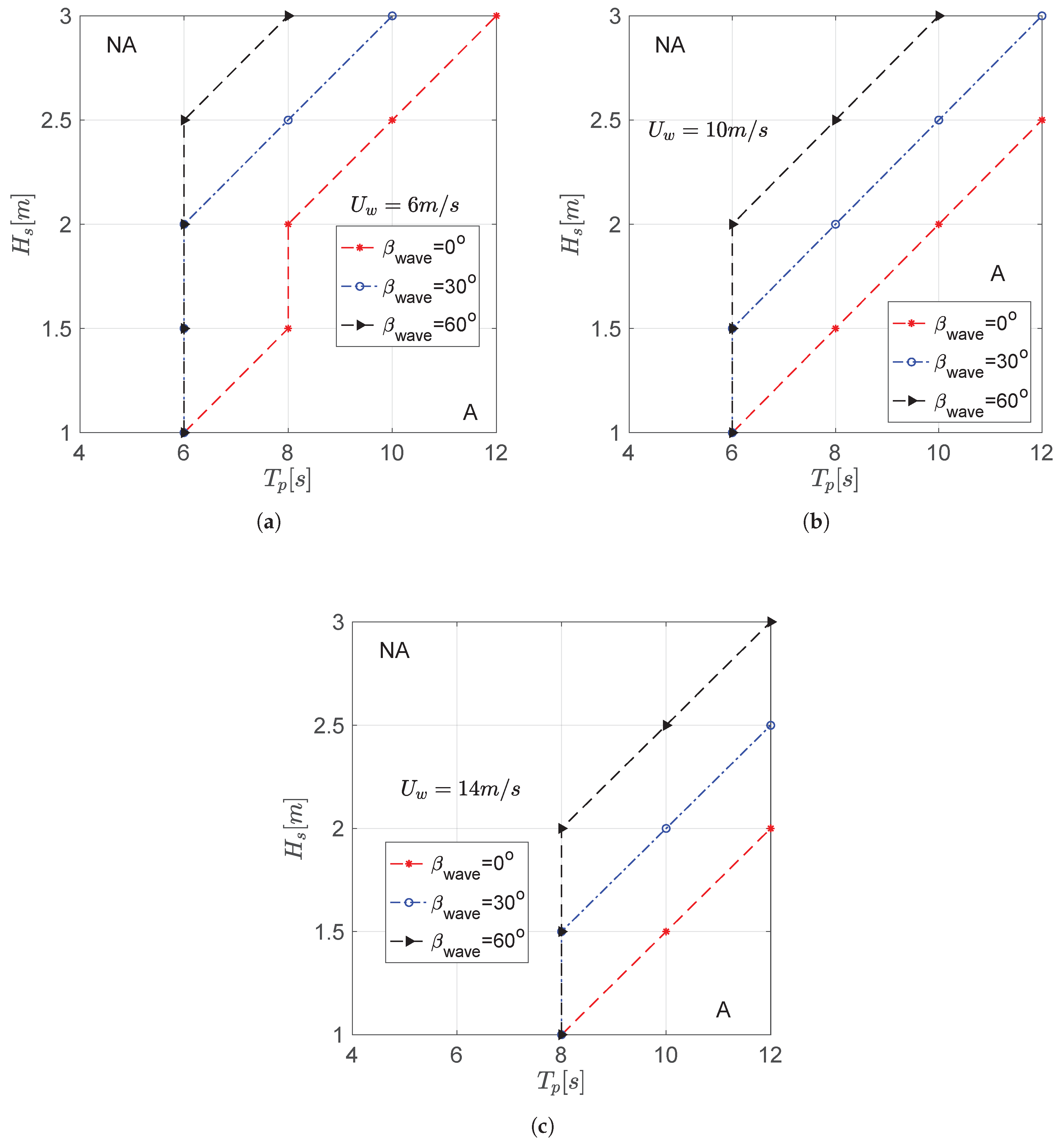
Finally, Figure 16a–c present the obtained operational limiting sea state curves in terms of H s , T p , β w a v e and three different U w = 6 m/s, 10 m/s, 14 m/s for blade-root mating task. The reason for representing the limiting sea state curves in terms of U w as the primary variable is because this parameter is considered principle source of decision variable during planning and execution of blade installation. Please note that the curve is obtained by comparing individual characteristic extreme responses with corresponding allowable levels, and any sea state on or below the curve is considered acceptable and thus safe for performing blade-root mating tasks. The limiting sea state curves are also illustrated with symbol ‘A’ (A represents acceptable sea state representing safe domain for the mating task) and ‘NA’ (NA represents non-acceptable sea state representing unsafe domain for the mating task). It is to be noted that although it is shown that limiting sea states increase along with misalignment between wind and wave conditions, a complete picture of the workability of the vessel is obtained only after considering the occurrence rate of such environment condition at an offshore site. In other words, a long-term assessment is required to consider the probability of occurrence of sea states. It can also be seen from the above figures that there are no environmental cases with T p = 4 s qualifying for the limiting sea state curves owing to resonance induced monopile vibrations. Also, there are less percentage of safe limiting sea states obtained for aligned wind–wave conditions ( β w a v e = 0 °) given that they cause sideways impact of the guide pin with hub, which is from a structural viewpoint more serious compared to head-on impact caused by misaligned wind–wave conditions. Also, the limiting sea state curve reduces with increasing mean wind speed ( U w ), and thus blade-root mating task have largest acceptable sea state curve for U w = 6 m/s and lowest for U w = 14 m/s.

7. Conclusions

The current paper presented a novel response-based methodology for estimating limiting sea states for blade-root mating task on a monopile-type offshore wind turbine. The impact risk between hub and root during the final mating phase was identified as a hazardous event that can cause failure of the installation task. The proposed methodology consisted of three related steps: (1) global response assessment of the mating system, (2) impact analysis of blade root with hub, and finally (3) comparison of characteristic values of extreme structural responses with allowable values to obtain limiting sea state curves. A case study was also presented in this paper to demonstrate the methodology. The mating task of DTU 10 MW blade was numerically modelled in HAWC2, and time-domain analyses were performed for various environmental conditions considering the North Sea center as a representative offshore site. The main conclusions from this study are described as follows:
1. The aerodynamic damping from the blades are limited in the monopile system during the wind-turbine blade installation task. Because of this limited damping characteristics, the monopile system is highly sensitive to wave-induced resonant responses during mating process. This is critical when the installation task is performed in the wave period close to the excitation frequency of the monopile structure in first fore-aft and side-side modes, causing resonance induced responses.
2. The motion of hub-center in the fore-aft direction is largest for load cases with β w a v e = 0 °, which further reduces with increase in the misalignment between wind and wave. Also, motion of hub-center in the side-side direction is highest for load cases with β w a v e = 60 °. It was also found that the spectral density of the hub-center responses are highest at T p = 4 s, and it further reduces with shift in the spectral peak period away from the excitation frequency of the monopile structure ( T p = 8 s, 12 s).
3. The impact velocity in the fore-aft direction ( V y i m p ) is largest for mating operation in load cases with aligned wind–wave conditions and wave period close to T p = 4 s.
4. A response spectrum analysis is performed for critical environmental cases and it was found that for all β w a v e , there are two important peaks obtained in the spectral density curves for V y i m p —(1) first pendulum blade mode about global y-axis which corresponds to 0.08 Hz, and (2) first fore-aft mode of the monopile which corresponds to 0.25 Hz. On the other hand, for spectral density curves corresponding to V x i m p , there are no peaks related to blade-root responses given that the wind is assumed in the fore-aft direction. There is only one peak observed at the 0.25 Hz, which corresponds to eigen frequency of the monopile in first side-side mode.
5. The results from the spectral density clearly imply that the sideways impact of the blade root with hub caused by impact velocity in the fore-aft direction is dominated by both blade root and hub responses. On the other hand, head-on impact between root and hub is contributed purely by hub responses.
6. The extreme value analysis for the limiting response parameters were performed, and it was found that the extreme value distributions of impact velocities (both fore-aft and side-side directions) fitted the Gumbel distributions satisfactorily. A chi-squared ( χ 2 ) goodness-of-fit hypothesis test for Gumbel cumulative distribution function is also performed and null hypothesis ( H o : data is represented by Gumbel distribution) was found to have been not rejected at the selected significance level of 5% (0.05).
7. Furthermore, a target exceedance probability of 10 2 was used to estimate the characteristic extreme responses which were compared with allowable impact velocities obtained from previous studies. The limiting sea state curves were obtained for different mean wind speed and it was found that aligned wind–wave conditions are more critical than misaligned wind–wave conditions for the blade-root mating task. This is because such a load case causes sideways impact of the guide pin, which is from a structural viewpoint more serious compared to head-on impact caused by misaligned wind–wave conditions.
8. The analyses of response parameters suggest that the parameter T p is essential for estimating limiting sea states given that this parameter significantly influences monopile vibrations during the blade-root mating task.

8. Limitations and Future Work

The following are the limitations and future work identified from the current study:
1. The present paper proposed a probability-based methodology for assessment of limiting sea states for blade installation using response-based criteria. The study demonstrated the method where three cases of wind–wave misalignment ( β w a v e = 0 °, 30°, 60°) were considered for the mating process. Although the method showed that the limiting sea states increase along with misalignment between wind and wave conditions, a complete picture of the workability of the vessel is obtained only after considering the occurrence rate of such environment condition at an offshore site. In other words, the method presented here lacks site-specific safety assessment, and therefore a long-term assessment is required to consider the probability of occurrence of sea states. Future work will consider introducing long-term parameters in the methodology to estimate the limiting sea states.
2. The proposed methodology used the characteristic values of impact velocities obtained from numerical analyses to estimate the limiting sea states. In principle, the methodology is purely response-based and thus uncertainties related to human factors needs to be addressed in the future given that the marine operations heavily rely on human participation during execution.
3. It is to be also noted the described methodology is applicable to blade-root mating process using other types of vessels such as catamaran floating crane vessels, and semi-submersible type floating crane vessels required for deep water applications. Future work will focus on assessment of limiting states for blade-mating process using floating crane vessels.
4. The proposed methodology estimates the limiting sea states exclusively for the blade-root mating process, where a hazardous event includes impact between guide pin and hub. In principle, wind-turbine blades can impact the surrounding structures such as preinstalled turbine tower during the lift-off phase, damaging the blade cross sections. Future work will focus on developing procedures for estimating the limiting sea states for such impact scenarios during blade installation.

Author Contributions

This research was carried out in collaboration between all authors. A.S.V. proposed the methodology, conducted the numerical simulations, and wrote the paper. Z.J., Z.R., Z.G., N.P.V. discussed the results and revised the manuscript. All authors read and approved the final manuscript.

Funding

This research was funded by the Research Council of Norway (RCN) project 237929 (Center for Research Innovation (SFI) MOVE) and project 223254 (Center of Excellence (CoE) NTNU AMOS).

Acknowledgments

This work has been financially supported by the Research Council of Norway granted through the Department of Marine Technology and the Centre for Research-based Innovation of Marine Operations (SFI MOVE) at NTNU project number 237929.The authors also appreciate research funding through Center of Excellence (CoE) NTNU AMOS project number 223254.

Conflicts of Interest

The authors declare no conflict of interest.

Abbreviations

AAcceptable sea state representing safe domain for the mating task
CDFCumulative Distribution Function
CFDComputational Fluid Dynamics
DNV-GLDet Norske Veritas-Germanischer Lloyd
DTUTechnical University of Denmark
ECEnvironmental Cases
FEMFinite Element Method
FFTFast Fourier Transformation
GWGigawatt
HAWC2Horizontal Axis Wind-Turbine Simulation Code 2nd generation
HzHertz
MWMegawatt
NANot Acceptable sea state representing unsafe domain for the mating task
NRELNational Renewable Energy Laboratory
OWTOffshore Wind-Turbine
OWTsOffshore Wind Turbines
PDFProbability Density Function
QRAsQualitative Risk Analyses
RMSERoot Mean Square Error
RSMResponse Surface Method
SFI MOVECentre for Research-based Innovation of Marine Operations
SIMOSimulation of Marine Operation- time-domain simulation program
STDStandard Deviation
2DTwo-dimensional

Nomenclature

H s Significant wave height (m)
T p Wave spectral peak period (s)
U w Mean wind speed (m/s)
β w i n d Direction of mean wind speed (degree)
β w a v e Degree of wind–wave misalignment (degree)
x g l o b a l , y g l o b a l , z g l o b a l Earth fixed global coordinate system used in HAWC2 simulations
V x i m p Impact velocity in side-side direction (head-on impact)-(m/s)
V y i m p Impact velocity in fore-aft direction (sideways impact)-(m/s)
V x a l l o w Allowable impact velocity in side-side direction (head-on impact)-(m/s)
V y a l l o w Allowable impact velocity in fore-aft direction (sideways impact)-(m/s)
I z ( S 33 ) Failure index in the transverse normal tensile stress
F V x ( V x i m p ) Extreme value distribution in side-side direction
F V y ( V y i m p ) Extreme value distribution in fore-aft direction
V x c h a r Characteristic impact velocity in side-side direction-(m/s)
V y c h a r Characteristic impact velocity in fore-aft direction-(m/s)
xGiven a sea state consisting of a particular combination of H s , T p , U w , β w a v e
XA set of load cases for which time-domain analysis of marine operation is performed
p y curvesPile–soil interaction curve representing lateral stiffness
f U w ( u ) Probability density function of mean wind speed
U x h u b Displacement of hub-center in side-side direction (m)
U y h u b Displacement of hub-center in fore-aft direction (m)
μ Location parameter of Gumbel distribution
β Shape parameter of Gumbel distribution
μ y i m p Location parameter of impact velocity in fore-aft direction for Gumbel distribution
β y i m p Shape parameter of impact velocity in fore-aft direction for Gumbel distribution
H o Null hypothesis for hypothesis testing

References

  1. Acero, W.I.G. Assessment of Marine Operations for Offshore Wind Turbine Installation with Emphasis on Response-Based Operational Limits. Ph.D. Thesis, Norwegian University of Science and Technology (NTNU), Trondheim, Norway, 2016. [Google Scholar]
  2. Renewable Power Generation Costs in 2017—IRENA. Available online: https://www.irena.org/-/media/Files/IRENA/Agency/Publication/2018/Jan/IRENA_2017_Power_Costs_2018.pdf (accessed on 1 March 2019).
  3. Nghiem, A.; Pineda, I. Wind Energy in Europe: Scenarios for 2030; Wind Europe: Brussels, Belgium, 2017. [Google Scholar]
  4. Wind Europe. The European Offshore Wind Industry–Key Trends and Statistics 2017; Technical Report; Wind Europe: Brussels, Belgium, 2017. [Google Scholar]
  5. Ahn, D.; Shin, S.C.; Kim, S.Y.; Kharoufi, H.; Kim, H.C. Comparative evaluation of different offshore wind turbine installation vessels for Korean west–south wind farm. Int. J. Naval Archit. Ocean Eng. 2017, 9, 45–54. [Google Scholar] [CrossRef] [Green Version]
  6. Verma, A.S.; Vedvik, N.P.; Gao, Z. A comprehensive numerical investigation of the impact behaviour of an offshore wind turbine blade due to impact loads during installation. Ocean Eng. 2019, 172, 127–145. [Google Scholar] [CrossRef]
  7. Picture. Available online: https://www.ntnu.edu/move/presentationFredOlsen (accessed on 10 March 2019).
  8. Acero, W.G.; Gao, Z.; Moan, T. Methodology for assessment of the allowable sea states during installation of an offshore wind turbine transition piece structure onto a monopile foundation. J. Offshore Mech. Arct. Eng. 2017, 139, 061901. [Google Scholar] [CrossRef]
  9. Gao, Z.; Guachamin Acero, W.; Li, L.; Zhao, Y.; Li, C.; Moan, T. Numerical simulation of marine operations and prediction of operability using response-based criteria with an application to installation of offshore wind turbine support structures. In Proceedings of the Third Marine Operations Specialty Symposium (MOSS2016), Singapore, 20–21 September 2016; pp. 20–21. [Google Scholar]
  10. Gintautas, T.; Sørensen, J.D.; Vatne, S.R. Towards a risk-based decision support for offshore wind turbine installation and operation & maintenance. Energy Procedia 2016, 94, 207–217. [Google Scholar]
  11. DNVGL Standard DNVGL-ST-N001, Marine Operations and Marine Warranty; DNVGL: Hovik, Norway, 2016.
  12. Hopstad, A.L.H.; Ronold, K.O.; Argyriadis, K. Revision of DNV GL Design Standard for Floating Wind Turbine Structures. In Proceedings of the ASME 2017 36th International Conference on Ocean, Offshore and Arctic Engineering, Trondheim, Norway, 25–30 June 2017; p. V009T12A002. [Google Scholar]
  13. DNV. Recommended Practice DNV-RP-H103, Modelling and Analysis of Marine Operations; DNVGL: Hovik, Norway, 2014. [Google Scholar]
  14. Clauss, G.; Riekert, T. Operational limitations of offshore crane vessels. In Proceedings of the Offshore Technology Conference, Houston, TX, USA, 7–10 May 1990. [Google Scholar]
  15. Clauss, G.; Saroukh, A.; Weede, H. Prediction of limiting seastates for pipelaying operation. In Proceedings of the 17th International Conference on Offshore Mechanics and Arctic Engineering, Lisbon, Portugal, 5–9 July 1998; p. 11. [Google Scholar]
  16. Morandi, A. Marine Warranty Survey for Jack-Ups. Encycl. Marit. Offshore Eng. 2017, 1–12. [Google Scholar] [CrossRef]
  17. Ringsberg, J.W.; Daun, V.; Olsson, F. Analysis of impact loads on a self-elevating unit during jacking operation. In Proceedings of the ASME 2015 34th International Conference on Ocean, Offshore and Arctic Engineering, St. John’s, NL, Canada, 31 May–5 June 2015; p. V003T02A096. [Google Scholar]
  18. Cozijn, J.; van der Wal, R.; Dunlop, C. Model Testing and Complex Numerical Simulations for Offshore Installation. In Proceedings of the Eighteenth International Offshore and Polar Engineering Conference, Vancouver, BC, Canada, 6–11 July 2008. [Google Scholar]
  19. Verma, A.S.; Jiang, Z.; Vedvik, N.P.; Gao, Z.; Ren, Z. Impact assessment of a wind turbine blade root during an offshore mating process. Eng. Struct. 2019, 180, 205–222. [Google Scholar] [CrossRef]
  20. Li, L.; Acero, W.G.; Gao, Z.; Moan, T. Assessment of allowable sea states during installation of offshore wind turbine monopiles with shallow penetration in the seabed. J. Offshore Mech. Arct. Eng. 2016, 138, 041902. [Google Scholar] [CrossRef]
  21. MARINTEK. SIMO-Theory Manual Version 4.6; MARINTEK: Trondheim, Norway, 2015. [Google Scholar]
  22. ANSYS, Inc. AQWA Theory Manual; ANSYS, Inc.: Canonsburg, PA, USA, 2013. [Google Scholar]
  23. Graczyk, M.; Sandvik, P.C. Study of landing and lift-off operation for wind turbine components on a ship deck. In Proceedings of the ASME 2012 31st International Conference on Ocean, Offshore and Arctic Engineering, Rio de Janeiro, Brazil, 1–6 July 2012; pp. 677–686. [Google Scholar]
  24. Jiang, Z.; Gao, Z.; Ren, Z.; Li, Y.; Lei, D. A parametric study on the blade final installation process for monopile wind turbines under rough environmental conditions. Eng. Struct. 2018, 172, 1042–1056. [Google Scholar] [CrossRef]
  25. Van Buren, E.; (Fred. Olsen Windcarrier, Oslo, Norway). Personal communication, 2018.
  26. Verma, A.S.; Gao, Z.; Jiang, Z.; Zhengru, R.; Vedvik, N.P. Structural dafety assessment of marine operations from a long term perspective: A case study of offshore wind turbine blade installation (Accepted). In Proceedings of the 38th International Conference on Ocean, Offshore and Arctic Engineering OMAE, Glasgow, UK, 9–14 June 2019. [Google Scholar]
  27. Verma, A.S.; Jiang, Z.; Gao, Z.; Vedvik, N.P. Effects of passive tuned mass damper on blade root impacts during offshore mating process. Mar. Struct. 2019. under review. [Google Scholar]
  28. Picture. Available online: http://www.siemens.co.uk/en/news_press/index/news_archive/2013/first-turbine-installed-at-gwynt-y-mor.htm (accessed on 23 March 2019).
  29. Picture Adapted. Available online: https://www.power-eng.com/articles/2016/10/siemens-receives-order-for-44-mw-onshore-wind-power-plant-in-croatia.html (accessed on 23 March 2019).
  30. Jiang, Z. The impact of a passive tuned mass damper on offshore single-blade installation. J. Wind Eng. Ind. Aerodyn. 2018, 176, 65–77. [Google Scholar] [CrossRef]
  31. Habali, S.; Saleh, I. Local design, testing and manufacturing of small mixed airfoil wind turbine blades of glass fiber reinforced plastics: Part I: Design of the blade and root. Energy Convers. Manag. 2000, 41, 249–280. [Google Scholar] [CrossRef]
  32. Larsen, T.J.; Hansen, A.M. How 2 HAWC2, the User’s Manual; Technical report; Risø National Laboratory: Roskilde, Denmark, 2007. [Google Scholar]
  33. Jonkman, J.; Butterfield, S.; Musial, W.; Scott, G. Definition of a 5-MW Reference Wind Turbine for Offshore System Development; Technical Report No. NREL/TP-500-38060; National Renewable Energy Laboratory: Golden, CO, USA, 2009. [Google Scholar]
  34. Ren, Z.; Jiang, Z.; Skjetne, R.; Gao, Z. Development and application of a simulator for offshore wind turbine blades installation. Ocean Eng. 2018, 166, 380–395. [Google Scholar] [CrossRef]
  35. Ren, Z.; Skjetne, R.; Jiang, Z.; Gao, Z.; Verma, A.S. Integrated GNSS/IMU hub motion estimator for offshore wind turbine blade installation. Mech. Syst. Signal Process. 2019, 123, 222–243. [Google Scholar] [CrossRef]
  36. Wang, W.; Bai, Y. Investigation on installation of offshore wind turbines. J. Mar. Sci. Appl. 2010, 9, 175–180. [Google Scholar] [CrossRef]
  37. Gaunaa, M.; Bergami, L.; Guntur, S.; Zahle, F. First-order aerodynamic and aeroelastic behavior of a single-blade installation setup. J. Phys. Conf. Ser. 2014, 524, 012073. [Google Scholar] [CrossRef]
  38. Gaunaa, M.; Heinz, J.; Skrzypiński, W. Toward an engineering model for the aerodynamic forces acting on wind turbine blades in quasisteady standstill and blade installation situations. J. Phys. Conf. Ser. 2016, 753, 022007. [Google Scholar] [CrossRef]
  39. Bak, C.; Zahle, F.; Bitsche, R.; Kim, T.; Yde, A.; Henriksen, L.C.; Hansen, M.H.; Natarajan, A. Description of the DTU 10 MW Reference Wind Turbine; Progress Report Report-I-0092; DTU Wind Energy: Roskilde, Denmark, 2013. [Google Scholar]
  40. Kuijken, L. Single Blade Installation for Large Wind Turbines in Extreme Wind Conditions. Master’s Thesis, Technical University of Denmark, Lyngby, Denmark, 2015. [Google Scholar]
  41. Zhao, Y.; Cheng, Z.; Sandvik, P.C.; Gao, Z.; Moan, T. An integrated dynamic analysis method for simulating installation of a single blade for offshore wind turbines. Ocean Eng. 2017, 152, 72–88. [Google Scholar] [CrossRef]
  42. Verma, A.S.; Jiang, Z.; Ren, Z.; Gao, Z.; Vedvik, N.P. Effects of wind-wave misalignment on a wind turbine blade mating process. J. Mar. Sci. Appl. 2019. under review. [Google Scholar]
  43. Ketele, S. Detailed Modeling of Connections in Large Composite Wind Turbine Blades. Master’s Thesis, Universiteit Gent, Welkom, South Africa, 2013. [Google Scholar]
  44. MARINTEK. SIMO-User Manual Version 4.4.1; MARINTEK: Trondheim, Norway, 2015. [Google Scholar]
  45. Ren, Z.; Skjetne, R.; Gao, Z. A Crane Overload Protection Controller for Blade Lifting Operation Based on Model Predictive Control. Energies 2019, 12, 50. [Google Scholar] [CrossRef]
  46. Hibbitt, H.; Karlsson, B.; Sorensen, P. Abaqus Analysis User’s Manual Version 2016; Dassault Systèmes Simulia Corp.: Providence, RI, USA, 2016. [Google Scholar]
  47. Bhashyam, G.R. ANSYS Mechanical—A Powerful Nonlinear Simulation Tool; Ansys, Inc.: Canonsburg, PA, USA, 2002; Volume 1, p. 39. [Google Scholar]
  48. Morison, J.; Johnson, J.; Schaaf, S. The force exerted by surface waves on piles. J. Pet. Technol. 1950, 2, 149–154. [Google Scholar] [CrossRef]
  49. Velarde, J. Design of Monopile Foundations to Support the DTU 10 MW Offshore Wind Turbine. Master’s Thesis, Norwegian University of Science and Technology (NTNU), Trondheim, Norway, 2016. [Google Scholar]
  50. Shirzadeh, R.; Devriendt, C.; Bidakhvidi, M.A.; Guillaume, P. Experimental and computational damping estimation of an offshore wind turbine on a monopile foundation. J. Wind Eng. Ind. Aerodyn. 2013, 120, 96–106. [Google Scholar] [CrossRef]
  51. Shirzadeh, R.; Weijtjens, W.; Guillaume, P.; Devriendt, C. The dynamics of an offshore wind turbine in parked conditions: A comparison between simulations and measurements. Wind Energy 2015, 18, 1685–1702. [Google Scholar] [CrossRef]
  52. Mann, J. The spatial structure of neutral atmospheric surface-layer turbulence. J. Fluid Mech. 1994, 273, 141–168. [Google Scholar] [CrossRef]
  53. Li, L.; Gao, Z.; Moan, T. Joint distribution of environmental condition at five European offshore sites for design of combined wind and wave energy devices. J. Offshore Mech. Arct. Eng. 2015, 137, 031901. [Google Scholar] [CrossRef]
  54. Montgomery, D.C. Design and Analysis of Experiments; John Wiley & Sons: Hoboken, NJ, USA, 2017. [Google Scholar]
  55. DNVGL. DNV-OS-H205–Lifting Operations Part 2-5; Offshore Standard; DNVGL: Hovik, Norway, 2014. [Google Scholar]
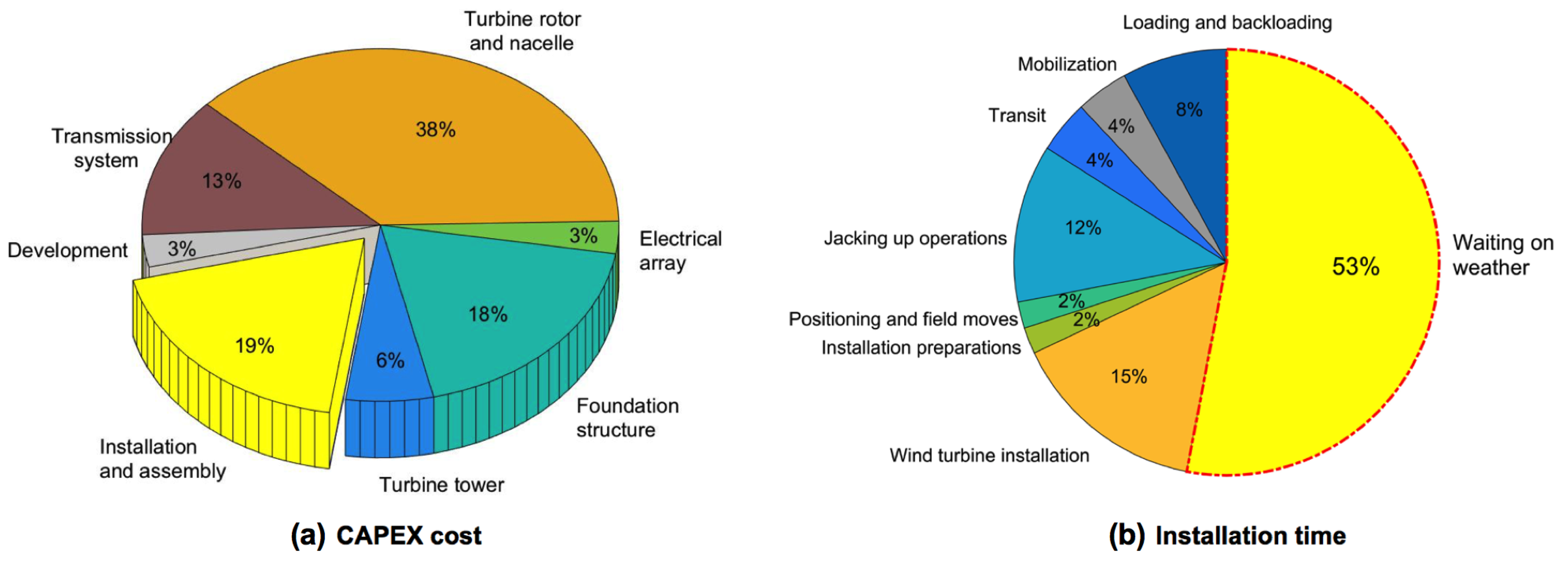
Figure 1. (a) Cost breakdown for different components of C a p E x for OWT project; (b) contribution of different activities during installation and assembly activities (statistics based on 2016–2017 data from [5,7]).
Energies 12 01867 g001
Figure 2. (a) Wind-turbine blade installation task using jack-up crane vessel [28]; (b) Magnified view of blade-root mating task [29].
Energies 12 01867 g002
Figure 3. Detailed procedure involved during blade-root mating task.
Energies 12 01867 g003
Figure 4. Critical event of blade-root impact with hub during mating: (a) impact scenarios, (b) failure modes at the blade root and (c) allowable impact velocities [42].
Energies 12 01867 g004
Figure 5. Response-based methodology for estimating operational limits for blade-root mating task.
Energies 12 01867 g005
Figure 6. Numerical modelling of installation system in HAWC2.
Energies 12 01867 g006
Figure 7. Description of North sea center offshore site (a) marginal PDF of mean wind speed ( f U w ( u ) ) (b) 2D-contour surface for H s - T p for different ranges of wind speeds (c) wind–wave misalignment ( β w a v e ) (d) bird view of wind-turbine blade-root mating task.
Energies 12 01867 g007
Figure 8. Displacement of the hub-center in side-side ( U x h u b ) and fore-aft directions ( U y h u b ) for H s = 2 m, U w = 8 m/s, T p = 4 s (a) β w a v e = 0 ° (b) β w a v e = 30 ° (c) β w a v e = 60 °.
Energies 12 01867 g008
Figure 9. (a) Displacement hub-center y displacement ( U y h u b ) (b) Spectral densities (c) Blade root y displacement (d) Spectral densities.
Energies 12 01867 g009
Figure 10. Response-time histories for V x i m p and V y i m p for load case H s = 2 m, T p = 4 s, U w = 8 m/s and for different wind–wave misalignment (a) β w a v e = 0 ° (b) β w a v e = 30 ° (c) β w a v e = 60 ° (d) comparison of standard deviations for V y i m p for different T p = 4 s, 6 s, 8 s, 10 s, and 12 s.
Energies 12 01867 g010
Figure 11. Spectral density curve for V x i m p and V y i m p for load case H s = 2 m, T p = 4 s, U w = 8 m/s and for different wind–wave misalignment (a) β w a v e = 0 ° (b) β w a v e = 30 ° (c) β w a v e = 60 °.
Energies 12 01867 g011aEnergies 12 01867 g011b
Figure 12. Fitting of the extreme (a) V x i m p (b) V y i m p to the Gumbel probability paper; (c) ( F V x ( V x i m p ) (d) F V y ( V y i m p ) ) for H s = 2 m, T p = 4 s, U w = 8 m/s and for different wind–wave misalignment β w a v e = 0 °, 30° and 60°.
Energies 12 01867 g012
Figure 13. 2D-response surface contour plot for Gumbel parameters ( μ y i m p , β y i m p ) for load case H s = 2 m, T p = 4 s, U w = 6 m/s: μ y i m p : (a) β w a v e = 0 °(b) β w a v e = 30 °(c) β w a v e = 60 °; β y i m p : (d) β w a v e = 0 °; (e) β w a v e = 30 °; (f) β w a v e = 60 °
Energies 12 01867 g013
Figure 14. Estimation and comparison of (a) V x c h a r (b) V y c h a r with V x , y a l l o w for H s = 2 m, T p = 4 s, U w = 8 m/s and β w a v e = 0 °, 30° and 60°; Estimation and comparison of (c) V x c h a r (d) V y c h a r with V x , y a l l o w for H s = 2 m, T p = 12 s, U w = 8 m/s and β w a v e = 0 °, 30° and 60° (green dots: V x , y c h a r V x , y a l l o w and red dots: V x , y c h a r V x , y a l l o w ).
Energies 12 01867 g014
Figure 15. Response surface for (a) V x c h a r and (b) V y c h a r for different H s , T p , β w a v e = 0 °, 30°, 60° and U w = 6 m/s.
Energies 12 01867 g015
Figure 16. Operational limiting sea state curves for different H s , T p , U w , β w a v e = 0 °, 30°, 60° with specific: (a) U w = 6 m/s (b) U w = 10 m/s (c) U w = 14 m/s (A: Acceptable domain and NA: Not acceptable domain for the mating task).
Energies 12 01867 g016
Table 1. Modelling parameters of installation system used in HAWC2 [19,27,42].
ParameterNotationValue
Diameter of monopile (m) ϕ D 9
Monopile penetration depth (m) P m 45
Water depth (m) d w 30
Natural period of first-fore aft mode (s) T F A 4.2
Damping ratio of first-fore aft mode ζ F A 1%
Blade mass (ton) M b d 41.7
Blade length (m) L b d 86.4
Blade-root diameter (m) D b d 3.54
Yoke weight (ton) W y k 50
Tugger line length (m) L t l 10
1st rotational mode of blade about y-axis (Hz) f r 1 0.08
Table 2. Environmental load cases considered in this study.
EC β wave H s (m) T p (s) U w (m/s)
11, 1.5, …, 3.04, 6, …, 126, 8, 10, 12, 14
230°1, 1.5, …, 3.04, 6, …, 126, 8, 10, 12, 14
360°1, 1.5, …, 3.04, 6, …, 126, 8, 10, 12, 14