Abstract
The half bridge (HB) modular multilevel converter (MMC) technology is considered a breakthrough to mitigate the shortcomings of the conventional voltage source converter (VSC) in high-voltage direct-current (HVDC) grid application. However, interruption of the DC fault is still a challenge due to fast di/dt and extremely high levels of DC fault current. The fault interruption using a DC circuit breaker (DCCB) causes enormous energy dissipation and voltage stress across the DCCB. Therefore, the use of a fault current limiter is essential, and the superconducting fault current limiter (SFCL) is the most promising choice. Past literature has focused on the operating characteristics of DCCB or limiting characteristics of the SFCL. However, there is little understanding about the fault interruption and system recovery characteristics considering both DCCB and SFCL. In this paper, we have presented a comparative study on fault interruption and system recovery characteristics considering three types of fault limiting devices in combination with circuit breaker. The transient analyses of AC and DC system have been performed, to suggest the most preferable protection scheme. It has been concluded that, amongst the three fault limiting devices, the Hybrid SFCL in combination with circuit breaker, delivers the most desirable performance in terms of interruption time, recovery time, energy dissipation and voltage transients.
1. Introduction
1.1. Motivation for Research
With the development of the voltage source converter (VSC), the realization of a high-voltage direct-current (HVDC) grid has become possible [1]. Nowadays, a modular multilevel converter (MMC) is considered the most promising VSC topology, due to its ability to achieve high equivalent frequency with lower switching frequency and specific modulation methods. The use of a modular structure has made it possible to achieve high levels of voltage, which are desirable for bulk power transmission [2,3].
Half bridge (HB) submodule and full bridge (FB) submodules are the most common submodule topologies used in MMCs [4,5,6,7,8]. The FB-MMC, is capable of interrupting DC fault currents. HB-MMC on the other hand cannot clear the DC fault because its freewheeling diodes act as uncontrolled rectifier bridges even when all the switching devices are blocked. Despite the limitations of HB-MMC, it is the most common and mature technology used for commercial realization of DC grids due to its relative advantage in terms of size, cost and power losses. Therefore, DC fault interruption by use of external protection device has become imperative for the application of HB-MMC based HVDC grid [9,10].
For the reliable and safe operation of a HVDC grid, the use of a HVDC circuit breaker (DCCB), which can quickly interrupt a DC fault current, is necessary [11,12]. However, the requirement of breaking a steeply increasing fault current, with high magnitudes and the absence of current zero, makes it a challenge to interrupt DC faults [13]. A few prototypes of the DCCB have been proposed, but a commercial solution has not been developed yet owing to the constantly increasing levels of fault currents, limited performance of breaker components like the ultrafast disconnector switch (UFS) and arc suppression chamber, high overvoltage and large fault energy dissipation [14,15,16]. Moreover, there is a lack of understanding regarding protection coordination when considering circuit breakers and converters in a HVDC system. To overcome the limitations of the DCCB, it has been recently proposed to connect a fault current limiter (FCL) in series to reduce the level of fault currents. A superconducting fault current limiter (SFCL) shows zero electrical resistance and high current density under normal operation, whereas a high resistance and low current density under fault conditions can aid the operation of a circuit breaker [17,18].
1.2. Literature Review
SFCLs have been widely investigated for the AC grid and their operating performance has been fully examined [19,20,21]. However, their application in the DC grid has not been investigated thoroughly. A few published papers have focused on limiting characteristics of SFCLs in HVDC grid application [22], economic evaluation [23] and optimization [24], and are limited to deriving appropriate impedance values without consideration of the recovery characteristics of SFCL [25]. In addition, interruption characteristics of DCCB in DC grid are dealt with in few papers, but the supportive role of SFCL for circuit breaker operation has not been considered with a thorough comparison of limiting and recovery characteristics [26,27,28]. From the overall view point of the HVDC grid, it is critical to verify the fault interruption and system restoration characteristics considering the DCCB, SFCL and converter. Therefore, in this work, we have presented for the first time a comparative study on fault interruption and system recovery characteristics considering three types of fault limiting devices in combination with a circuit breaker. The research results will be valuable for academics and engineers who are studying protection coordination considering protection devices like DCCB and SFCL.
1.3. Proposed Approach
Three types of SFCLs, namely resistive SFCL (R-SFCL), saturated iron core SFCL (SI-SFCL) and Hybrid SFCL (Hybrid-SFCL) are designed in Matlab/Simulink. As a DCCB, the hybrid DC circuit breaker (HCB) which can cope with the expected rapid rise of the fault current within 3 ms, is designed and applied in an HVDC grid [29,30,31]. The combination of a circuit breaker and SFCL was used in conjunction with a 50 level HVDC system. The fault interruption characteristics of HB-MMC in combination with a circuit breaker and SFCL are examined to identify the optimal protection scheme. The fault current and voltage transient on AC and DC side are analyzed for all the above-mentioned schemes.
The transient analysis of the AC and DC systems was performed according to the value of the current limiting reactor of the DC side without applying the SFCL. SFCL was later applied to verify energy dissipation during the fault interruption performance and transient voltage characteristics. Based on the above simulation, an optimal current limiting reactor was obtained for each SFCL. It was then applied to study the fault interruption performance of each protection scheme. Since the power system must withstand the fault current and the voltage stress resulting from the fault, the current and voltage transients on the AC and DC sides of the power system for the three schemes were thoroughly analyzed. Current interruption time, maximum fault current magnitude, rate of rise of fault current (di/dt), energy dissipated across the protection devices, voltage stress across DCCB, maximum overvoltage magnitude and voltage dip have been compared.
From the result, the strength and weaknesses of three cases are summarized, and then the suitable protection scheme from the point of view of fault handling and reclosing performance has been proposed. Finally, the design requirements of the optimal protection scheme have been identified.
This paper is organized as follows. The methodology is presented in Section 2. The simulation model and overall operation characteristics of each protection scheme are explained in Section 3. The effect in AC, DC system according to the variable current limiting reactor is presented in Section 4. In Section 5, the fault interruption performance with combination of circuit breaker, SFCL and HVDC system are simulated, and the results are presented in detail. In Section 6, the design requirement of preferable protection scheme is suggested through additional simulation analysis. The conclusion based on the summary of simulation results is presented in Section 7.
2. Methodology
The current and voltage transients on the AC and DC sides of the power system for the three protection schemes have been analyzed using the following method:
- Develop the test-bed model composed of the half bridge modular multilevel converter (HB-MMC) based HVDC system.
- Develop the hybrid DC circuit breaker (HCB) and install the circuit breaker in series with the DC line.
- Identify the minimum value of current limiting reactor that can provide sufficient time for HCB operation.
- Perform the transient analysis of the AC and DC systems according to the value of the current limiting reactor without applying the SFCL.
- Evaluate key parameters to assess the fault handling performance i.e., fault current limiting ratio, rate of rise of fault current (di/dt), total interruption time, maximum overvoltage and energy dissipation across the HCB.
- Develop the three types of superconducting fault current limiter (SFCL) namely resistive SFCL (R-SFCL), saturated iron core SFCL (SI-SFCL) and Hybrid SFCL (Hybrid-SFCL) and install the SFCLs in series with the HCB.
- Examine the need for an additional current limiting reactor according to the protection scheme
- The following parameters were analyzed considering all the fault protection schemes.
- The maximum AC overcurrent in fault period and AC overvoltage in reclosing period were measured.
- The maximum DC fault current, maximum rate of rise of fault current (di/dt) and total interruption time (ms) were measured.
- The voltage across the DCCB, DC voltage dip, energy dissipation across the DCCB and the SFCL during fault period were measured.
- The maximum DC overvoltage and energy dissipation across the SFCL during reclosing period were measured.
- Examine the suitability of each protection scheme considering protection coordination requirement in HB-MMC HVDC grid.
- The overall performance of three protection schemes was then compared in detail.
- The preferable protection scheme (Case 3: HB-MMC + Hybrid-SFCL + HCB) for application in HB-MMC HVDC grid was suggested.
- Suggest the method to optimize the design of protection scheme (Case 3).
3. Simulation Model
3.1. Test Bed Model
As shown in Figure 1, to examine the appropriate protection scheme for a half bridge modular multilevel converter (HB-MMC) based HVDC grid, a test bed model was developed in Matlab/Simulink [32]. A point-to-point HVDC system using 50-level HB-MMC was modelled. DC link voltage and current, is set at ±80 kV and 400 A, respectively.
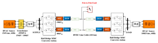
Figure 1.
Schematic diagram of HB-MMC HVDC System in Matlab/Simulink.
To simulate the worst DC fault, a pole-to-pole fault is introduced close to the rectifier. The superconducting fault current limiter (SFCL) and DC circuit breaker (DCCB) are installed in series with the DC line to limit and break the fault currents. The DC fault occurs at 0.2 s, and the reclosing is set to start at 0.4 s for complete analysis of fault transients. A delay of 0.2 s allows the fault path to deionize. The de-blocking of the converter and reclosing of the circuit breaker is initiated after the delay.
In steady state, the system is operated with constant active and reactive power control. In the transient state, HB-MMC is tripped by the main controller within 0.5 ms to protect the converter. Table 1 shows a summary of parameters of the HB-MMC system.

Table 1.
Parameters of HB-MMC HVDC system.
3.2. Protection Schemes in HB-MMC HVDC System
During a DC fault with half bridge modular multilevel converter (HB-MMC), the current will flow from the AC grid to the DC fault, in a similar way as with two-level VSC converters [33]. In other words, this topology does not have the capability to block DC fault as shown in Figure 2. The passage of large fault currents has the potential to damage IGBTs.
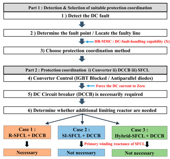
Figure 2.
Comparison of overall operating characteristics and the need for an additional current limiting reactor.
The capacitors of HB submodule will not discharge into the fault, which is an advantage compared with a two-level topology. This will result in less fault current stress (inrush current) and faster response during the system recovery in transient DC faults [33,34]. Nevertheless, a large fault current and high fault current rising rate (di/dt) necessitate the use of the fault current interruption device. Therefore, we proposed three types of protection schemes based on circuit breaker and superconducting fault current limiters (SFCLs) and analyzed their feasibility for application in HVDC grid.
Figure 2 shows whether an additional limiting reactor is required for each protection scheme. In the protection schemes consisting of a saturated iron core superconducting fault current limiter (SI-SFCL) or hybrid superconducting fault current limiter (Hybrid-SFCL), it is possible not only to have a reactor in the primary winding of the primary side, but also to increase the reactance value within a short time in the case of a DC fault. Therefore, no additional limiting reactor is required. However, in the protection scheme with R-SFCL, an additional limiting reactor on the DC side is necessary to lower the rate of rise of fault current so that more time can be allowed for circuit breaker to operate.
3.2.1. Case 1: Protection Scheme (HB-MMC + R-SFCL + HCB)
As mentioned above, a limiting reactor is essential in front of the DC circuit breaker (DCCB) to allow time required for the correct operation of the DCCB. A protection scheme composed of R-SFCL and HCB in the HVDC system is shown in Figure 3. To provide ample operation time to HCB, current limiting reactor reduces the rate of rise of fault current (di/dt). In this case, it must be carefully considered in the design because it has a constant value in both the steady state and transient state. In Section 4, we considered the effect of the size of current limiting reactor on AC and DC systems.
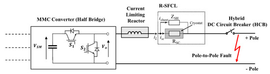
Figure 3.
Case 1: Protection scheme composed of HB-MMC, R-SFCL and HCB.
The electrical circuit of a R-SFCL is shown in Figure 3. A high temperature superconducting fault current limiter based on resistive YBCO was selected [35,36]. The mathematical model of R-SFCL considering current limiting and recovery characteristics can be expressed as previous literature [18,37]:
where Rsc denotes maximum quenching resistance in the quenching state, Tc is time constant of the SFCL during transition from the superconducting state to the normal state. The maximum recovery time of R-SFCL is considered to be 2 s based on the literature [38,39]. During the normal operation, DC current is flowing through the superconducting element RSFCL which dissipates low energy. If the current rises above the critical current value, the resistance RSFCL increases rapidly. The resistance in parallel ZSH to the superconductor is needed to protect the superconductor from destructive hot spots during the quench. In addition, this parallel resistance adjusts the limited current and avoids over voltages that could occur if RSFCL rises too rapidly [40,41].
3.2.2. Case 2: Protection Scheme (HB-MMC + SI-SFCL + HCB)
In this protection scheme, current limiting reactor is not necessary as shown in Figure 2. When DC fault occurs, the reactance of SI-SFCL increases rapidly, replacing the role of limiting reactor. As a result, it allows more time for the hybrid DC circuit breaker (HCB) to operate. However, unlike the protection scheme in Case 1, the SI-SFCL of Case 2 requires a considerable amount of iron because it has to limit the fault current without additional limiting reactors.
As shown in Figure 4, it is composed of two magnetic iron cores, two AC windings and one superconducting DC bias coil [42]. Unlike the R-SFCL of Case 1, which relies on the quenching of the superconductor to achieve increased impedance, it utilizes the dynamic behavior of the magnetic properties of iron to change the inductive reactance on the DC line [24]. A detailed description of SI-SFCL is given in our previous work [18].
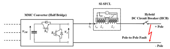
Figure 4.
Case 2: Protection scheme composed of HB-MMC, SI-SFCL and HCB.
Under normal operation, two cores are operating in saturation mode and their inductances are low. When DC fault occurs, the iron core is no longer saturated, and the coil inductance increases rapidly [43]. Although the SI-SFCL has the disadvantage of excessive bulk and weight due to the need of the iron core, it shows attractive features such as fast recovery without quenching, low steady state loss, and immediate current limiting. Therefore, it will be useful for high voltage design with high power quality and reliability.
3.2.3. Case 3: Protection Scheme (HB-MMC + Hybrid-SFCL + HCB)
This protection scheme is composed of a Hybrid-SFCL and hybrid DC circuit breaker (HCB) as shown in Figure 5.
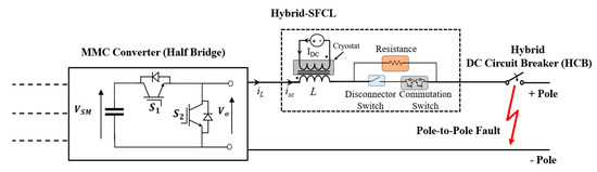
Figure 5.
Case 3: Protection scheme composed of HB-MMC, Hybrid-SFCL and HCB.
The conventional Hybrid SFCL, is not suitable in terms of reclosing and protection coordination considering the requirements of DC grid because of the extended time required for SFCL recovery following its quenching [44]. Therefore, a novel Hybrid-SFCL for DC grid application is designed through combination of resistance and reactance component which at the same time overcomes the limitations of the heavy iron core of SI-SFCL in Case 2.
The structure of a Hybrid-SFCL was designed through a combination with resistance and reactance to complement the bulky and heavy iron core of SI-SFCL in Case 2. While the secondary side reactance component of SI-SFCL is reduced considerably, the fault current is limited by the impedance that combines resistance and reactance by connecting the resistors in parallel.
To simplify the operating characteristics of Hybrid-SFCL, the equivalent circuits are given in Figure 6. In normal operation, the disconnector switch is closed and the DC line current isc is flowing through the low impedance primary inductor as shown in Figure 6a. The primary inductance Lmin can also act as a smoothing reactor to reduce the harmonic voltage and current of DC system. Low energy loss is beneficial to the long term operation of equipment installed in series in DC systems.

Figure 6.
Operation status of the Hybrid-SFCL: (a) in normal operation; (b) in limiting state I (t = t1); (c) in limiting state II (t = t2 = t1 + ∆t).
When the fault occurs, the current isc increases quickly. The iron core is no longer saturated and the coil inductance increases rapidly. Figure 6b depicts the limiting state I. It can be seen that the IGBT switch is turned off within 0.2 ms after the fault occurs, which results in the commutation of the fault current. The current is finally limited through the resistance component to exhibit the same limiting characteristics. Compared with the SI-SFCL in Case 2, the reactance size is relatively small. The coil inductance is designed within a range that allows the operation of circuit breaker. Figure 6c depicts the limiting state II. Despite the commutation of the fault current, current flows through the main path. Therefore, the current through main path is completely interrupted within 1 ms via the ultra-fast dis-connector switch.
The Hybrid-SFCL is designed to overcome the drawbacks of the bulky and heavy iron core while maintaining the advantages of SI-SFCL. The simulations related to design requirement were performed in detail and have been presented in Section 6. Based on this, we proposed the most suitable protection scheme for HB-MMC HVDC grid.
3.3. Protection Coordination in HB-MMC HVDC System
The coordination among superconducting fault current limiter (SFCL) and hybrid DC circuit breaker (HCB) is important for safe and reliable operation of HVDC grid. Figure 7 shows the protection coordination process in the half bridge modular multilevel converter (HB-MMC) grid. When a DC fault occurs at 0.2 s, the HB-MMC is tripped by the main controller within 0.5 ms to protect the converter as shown in T1.
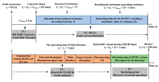
Figure 7.
Protection coordination with SFCLs, HCB and HB-MMC.
In T2, the response time of the DC circuit breaker (DCCB) and SFCL is regarded as an important technical indicator. If the response time of the SFCL is faster than the operation time of the main breaker in the DCCB, the fault interruption requirement on the circuit breaker may be reduced. In other words, before the main interrupter of the circuit breaker operates, the SFCL must operate quickly to reduce the fault interruption level required by the circuit breaker [45]. R-SFCL, SI-SFCL and Hybrid-SFCL can all satisfy the aforementioned requirement.
T3 is closely related to T2. In R-SFCL, since additional limiting reactor is present in the DC line, the allowable time for circuit breaker operation can be increased. In addition, the reactor component of SI-SFCL and the Hybrid-SFCL is sufficient to limit the fault current to suitable value for convenient operation of the main circuit breaker. The operation process of the HCB is described in detail in our previous research [32].
In T4, HB-MMC, SFCL and DCCB must recover so that reclosing operation can be performed to attempt system recovery. Considering that the HVDC system restoration should be performed within 300 ms, fast recovery time of protection devices is of utmost importance to achieve this goal [46,47,48]. R-SFCL, takes several seconds to several minutes for recovery, and therefore cannot satisfy the reclosing condition despite the fast operation capability of the circuit breaker and HB-MMC converter as shown in T4. On the other hand, SI-SFCL and Hybrid-SFCL have no quenching characteristics and thus have a fast recovery time of about 0.002 s. Therefore, it can be confirmed that the circuit breaker, SFCL, and converter recover in the T4, and system can be easily restored.
4. Transient Performance of the System in DC Faults According to the Variable Limiting Reactor
In this section, we have simulated how the value of current limiting reactor affects AC and DC systems. The comparison between fault interruption performance and energy dissipation were performed through application of a circuit breaker in HVDC grid.
4.1. Analysis of the Current and Voltage Transient of the AC and DC Sides
The simulation was performed by classifying the current limiting reactor values into five cases. All other conditions were identical.
4.1.1. Transient Current and Voltage of the AC System
Figure 8 shows the transient current waveform of AC side considering the variable limiting reactor.
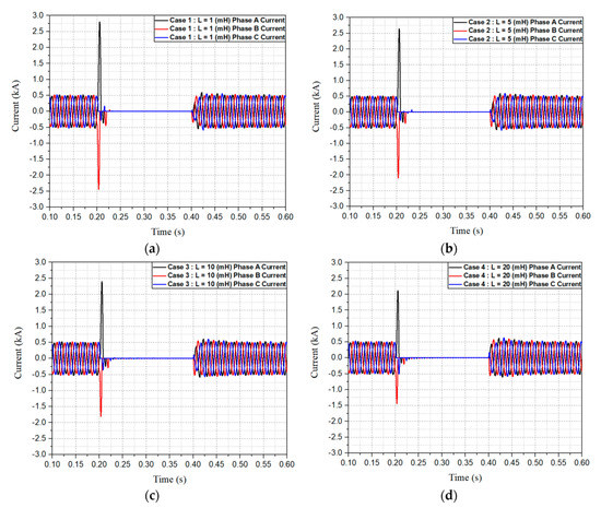
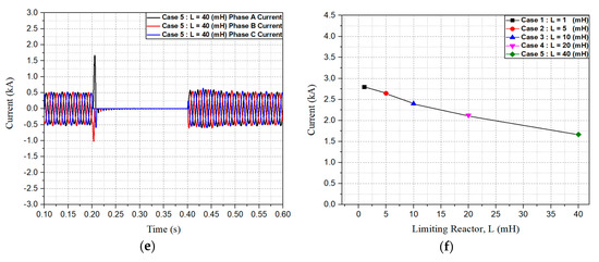
Figure 8.
The transient current waveforms of the AC system considering the variable current limiting reactor: (a) Case 1: L = 1 (mH); (b) Case 2: L = 5 (mH); (c) Case 3: L = 10 (mH); (d) Case 4: L = 20 (mH); (e) Case 5: L = 40 (mH); (f) comparison of maximum overcurrent in transient state.
When DC fault occurs at 0.2 s, it is confirmed that overcurrent occurs for one half period in one phase. As the value of the current limiting reactor increases, the overcurrent value of the AC side gradually decreases. In other words, in transient fault period, the larger the reactance component in the DC side, the lower the system stress will be in the AC side. In Figure 8f, the results of this simulation are summarized.
Figure 9 shows the transient voltage waveform of AC side considering the variable limiting reactor. In the 0.2 s where DC fault occurs, it is confirmed that overvoltage occurs for one half period in one phase. Figure 9f shows that the larger the current limiting reactor value of the DC side, the smaller the overvoltage value of the AC side. That is, in the DC fault period, the presence of a sufficient reactance component of the DC line plays an important role in reducing the system stress of the AC side. Based on this simulation, we designed each protection scheme considering the large reactance value, i.e., the large impedance component, in the transient section.
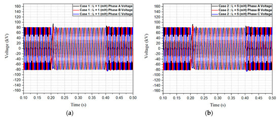
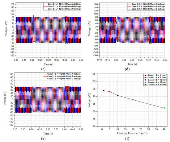
Figure 9.
The transient voltage waveforms of the AC system considering the variable current limiting reactor: (a) Case 1: L = 1 (mH); (b) Case 2: L = 5 (mH); (c) Case 3: L = 10 (mH); (d) Case 4: L = 20 (mH); (e) Case 5: L = 40 (mH); (f) comparison of maximum overvoltage in transient state.
4.1.2. Transient Current and Voltage of the DC System
Figure 10 shows the DC side transient current and voltage because of pole-to-pole fault. As shown in Figure 10a, the rate of rise of fault current and fault current limiting ratio decreases as the value of limiting reactor is increased.
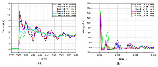
Figure 10.
The DC current and voltage waveform in transient state without SFCL: (a) current waveform; (b) voltage waveform measured at converter terminals.
A reduction in the rate of rise of fault current (di/dt) allows more time for the circuit breaker to operate. Therefore, adequate design of limiting reactor is important.
4.1.3. Fault Interruption Performance
In the above simulation results, we concluded that designing a large limiting reactance is advantageous for reducing the overall stress on the system during fault. However, when considering the DC circuit breaker (DCCB) application, which is essential in the half bridge modular multilevel converter (HB-MMC) HVDC grid, it is important to verify whether the interruption performance fully meets the above design conditions.
In this section, we compared the interruption performance of circuit breaker considering the limiting reactance on the DC line as a variable. The results are shown in Figure 11.
Figure 11.
The DC current and voltage waveform in transient state: (a) current waveform; (b) voltage waveform measured at converter terminals.
The fault current limiting ratio, rate of rise of fault current (di/dt), total interruption time and energy dissipation across circuit breaker are considered key parameters for evaluating the fault handling performance.
As shown in Figure 11a, the larger the value of the limiting reactor, the greater the limiting ratio. However, despite the main breaker opening at 0.201 s, the presence of large reactor allows the fault current to increase for a while before it starts to decrease. The interruption time and the energy dissipation also increased as a result.
Case 5 shows that even after 0.201 s, the fault current continues to increase, and the interruption time is delayed by 1 ms compared to Case 1. Large reactors also have a disadvantage in terms of size, weight, and cost. To overcome this disadvantage, a protection scheme (Case 3) that limits the fault current through a combination of resistance and reactance component, was suggested in Section 5, and an evaluation of this was also discussed in detail. Figure 11b shows the DC voltage waveform on the converter terminal in transient state. The smaller the limiting reactor value, the larger the voltage dip.
Figure 12 shows comparison of the energy dissipation across circuit breaker considering the limiting reactor as a variable. As the value of limiting reactor increases, the fault current limiting ratio decreases, and the energy dissipation decreases as well.
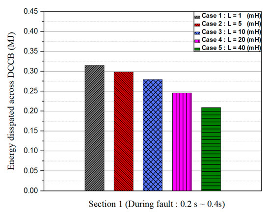
Figure 12.
The comparison of energy dissipation across DCCB during fault period.
5. Transient Performance of the System with SFCLs and DCCB in DC Faults
In this section, we compared the transient performance of the three protection schemes mentioned in Section 3. For comparison of this performance, a pole-to-pole fault was introduced near the rectifier at 0.2 s. The system recovery time was set to 0.4 s.
Based on the simulation results in Figure 11a, a current limiting reactance design of protection scheme (Case 1) was performed. After applying a current limiting reactor value of 1 mH, which is the minimum value for providing sufficient time for circuit breaker operation, the fault current limiting ratio can be reduced by about 50% (from 8.5 kA to 4.3 kA) through the quenching resistance (12 ohm) of R-SFCL.
To compare three types of protection schemes in similar operating conditions, the current limiting impedances of saturated iron core superconducting fault current limiter (SI-SFCL) and Hybrid-SFCL were designed to be identical, and Hybrid-SFCL was also designed through a combination of resistance and reactance values. The specific design requirements of the Hybrid-SFCL for application of HB-MMC HVDC grid are discussed in Section 6.
5.1. Analysis of the Transient Characteristics of the AC and DC Grid According to Protection Schemes
5.1.1. Transient Current and Voltage of the DC System and Energy Dissipation across Protection Devices
Figure 13a shows a current waveform comparing fault interruption performance of different protection schemes. By applying similar limiting impedance in all schemes, the fault current limiting ratio is measured to be 4.3 kA in all cases.
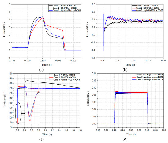
Figure 13.
The DC current and voltage waveform in transient state according to protection scheme: (a) current waveform in fault period; (b) current waveform in recovery period; (c) voltage waveform in transient state; (d) voltage waveform across DCCB.
In Case 2 (SI-SFCL + DCCB) and Case 3 (Hybrid-SFCL + DCCB), the presence of a reactance component in the superconducting fault current limiter (SFCL) allowed the DC circuit breaker (DCCB) sufficient operation time, and the fault current decreased after 0.201 s.
Here, in Case 2, since there is a large reactance component even after the main breaker operation, the fault current decreases rather slowly. This has a detrimental effect on interruption time and energy dissipation.
On the other hand, in Case 3, since the fault current is limited by the resistance and the reactance component after the main breaker operation, the fault current decreases relatively rapidly. As a result, it was confirmed that the total interruption time was relatively lower than Case 2, and the energy dissipation across circuit breaker was smallest as shown in Figure 14.
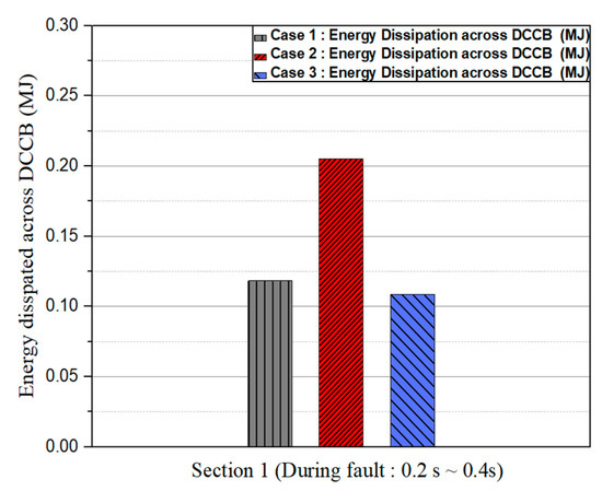
Figure 14.
The comparison of energy dissipation across DCCB during fault period.
In Case 1 (R-SFCL + DCCB), the rate of rise of fault current (di/dt) was relatively high compared to Case 2 and Case 3 due to the absence of the large reactor component. Reduction of the peak fault current by SFCL before operation of main breaker of DCCB, decreasing the peak value by R-SFCL can be advantageous in terms of limiting characteristics, but a high di/dt can have its own detriments. The first one is to cause converter blocking when the DC fault current exceeds the critical blocking current, and the other is the possibility of circuit breaker tripping failure.
Figure 13b shows the current waveform during the system recovery period. In Case 1, since the R-SFCL takes a long time to achieve its pre-fault resistance, the resistive component will remain during restoration of the DC grid. In Case 2 and Case 3, the SFCL is fully recovered before the converter de-blocking. Despite the difference in recovery time of each SFCL, we found that the settling time for all three cases was almost the same due to the response time of DC current controller.
Figure 13c shows the DC voltage in the transient state. Although the fault will be quickly removed by a circuit breaker, there will be a voltage dip until the protective device begins operation. The lower the voltage dip, the stronger the system will be because the voltage dip affects the power quality of a system and other sensitive electronics equipment in various ways based on the dip characteristic. In Figure 13c, it can be seen that the voltage dip is the largest in Case 2 (43.7% of the normal voltage), whereas Case 1 (37.5% of the normal voltage) and Case 3 (34.3% of the normal voltage) were respectively lower.
However, in the recovery period, there was a big difference in terms of overvoltage magnitude and its duration. In Case 2 and Case 3, there was a brief period of overvoltage before recovery to the steady-state voltage. Fast voltage recovery is beneficial in terms of insulation design because it applies relatively low voltage stress to various power system components during the transient period. But, Case 1 showed the peak overvoltage of 178 kV which is much higher than the other two cases. In addition, the overvoltage reduced rather slowly, and significant values of overvoltage stress sustained for more than 1 s. This may increase the insulation requirements of many components of DC grid.
Figure 13d shows the voltage stress across the circuit breaker during the DC fault. As shown in Figure 13a, in Case 1, since the peak current value is decreased by the SFCL before the main breaker operation, the stress applied to the circuit breaker is relatively low. On the other hand, in Case 2 and Case 3, since the peak current value of the main path is almost the same, the voltage stress applied to the circuit breaker is almost the same as well.
Figure 15a shows the voltage waveform across SFCL in transient state. When a DC fault occurs, the voltage stress of Case 1 is measured to be 50 kV, which is the highest value in all Cases. In the recovery period, the voltage across R-SFCL was maintained at a relatively high value for a long time and recovered slowly. As a result, it had to endure higher losses due to the presence of recovery voltage.
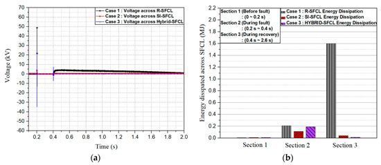
Figure 15.
The comparison of voltage and energy dissipation across SFCL: (a) voltage waveform across SFCL; (b) energy dissipation across SFCL.
As shown in Figure 15b, the energy dissipation across the R-SFCL and Hybrid-SFCL is measured to be 0.2 MJ and 0.18 MJ during fault period. In the case of Hybrid-SFCL, the energy dissipation of solid-state switches is considered in addition to that of reactive and resistive components in hybrid-SFCL. Energy dissipation by solid state switches during interruption operation is insignificant because of its high-speed nature. In SI-SFCL of Case 2, the loss is 0.1 MJ.
In Section 4, even in the reclosing period, the R-SFCL did not recover, indicating that the energy dissipation was considerably larger when compared with Case 2 and Case 3. In Case 3, the energy dissipation of solid-state switches is not negligible. However, in both states, switch energy dissipation does not exceed a few hundred Joules and hence it cannot be noticed in the graph, when compared to the energy dissipation of a few Mega Joules across the resistance.
5.1.2. Transient Current and Voltage of the AC System
Figure 16 shows AC current waveform in transient state. The maximum overcurrent magnitude shows a little difference according to the component of limiting impedance in DC side. It results from the difference in total interruption time achieved by different protection schemes as shown in Figure 13a.
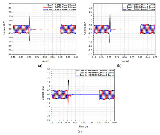
Figure 16.
The transient current waveforms of the AC system according to the protection scheme: (a) Case 1: Protection scheme (R-SFCL and HCB); (b) Case 2: Protection scheme (SI-SFCL and HCB); (c) Case 3: Protection scheme (Hybrid-SFCL and HCB).
The overcurrent magnitude in Case 1 has been confirmed to be the lowest among the three cases. In the resistive superconducting fault current limiter (R-SFCL), which limits the current by its quenching resistance, the rate of rise of current (di/dt) is high due to the presence of a small reactive component. As a result, the overcurrent on the AC side is relatively lower. On the other hand, the current magnitude in Case 2 was measured to be 2.2 kA which is the highest value.
Even with the same limiting impedance, saturated iron core superconducting fault current limiter (SI-SFCL) with large reactance seems to have a relatively small impact on the AC side overcurrent reduction, since it makes the rate of rise of current (di/dt) relatively low. In Case 3, the overcurrent is lower than Case 2 because the impedance component is the result of resistance and reactance component.
Figure 17 shows voltage waveform in the transient state. In the DC fault period, the maximum overvoltage magnitude was measured to be 90 kV in Case 2 due to large reactance of SI-SFCL, as shown in Figure 17b. In Case 1, sustained overvoltage can be seen during system restoration, due to a relatively long recovery time of R-SFCL. The DC power reaches its prefault level after complete recovery of R-SFCL. Due to the diminished level of DC power during this intermediate period, the transient overvoltage can be seen in the AC side as shown in Figure 17a. In this case, the voltage will be restored to normal voltage only after the recovery of SFCL is completed.
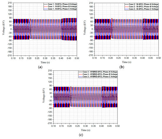
Figure 17.
The transient voltage waveforms of the AC system according to the protection scheme: (a) Case 1: Protection scheme (R-SFCL and HCB); (b) Case 2: Protection scheme (SI-SFCL and HCB); (c) Case 3: Protection scheme (Hybrid-SFCL and HCB).
Therefore, considering the protection coordination and restoration requirement in a HVDC grid, Case 1 is not suitable.
5.2. The Preferable Protection Scheme for the HB-MMC HVDC Grid
In this section, the simulation results of three protection schemes were compared and preferable scheme was proposed for HVDC grid. Finally, the merits of using Case 3 (Hybrid SFCL + DCCB) instead of Case 2 (SI-SFCL + DCCB) were highlighted.
5.2.1. Comparison of Three Types of Protection Scheme
To suggest a preferable protection scheme in the half bridge modular multilevel converter (HB-MMC) HVDC grid, it is important to discuss the reclosing requirement considering the current limitations and recovery characteristics of the protection devices. Under the same simulation conditions, we proposed a preferred protection scheme for the HVDC grid by conducting a comparative study on the strengths and weaknesses of each protection scheme. The comparison of three protection schemes is summarized in Table 2.
Table 2.
Comparison of the three protection schemes for HB-MMC HVDC grid application.
In Case 1 (R-SFCL + DCCB), the resistive superconducting fault current limiter (R-SFCL) is relatively compact, light-weight, and has a satisfactory fault current limiting performance. However, when the rate of rise of fault current is high, AC and DC overvoltage are maximum, stress on insulation and energy dissipation is quite high as well. An additional, current limiting reactor is also required in series to assist the operation of circuit breaker. HVDC grid restoration requirement poses another limitation on the choice of protection scheme. Although there is no commercial standard related to the reclosing time of the HVDC grid, it should be relatively shorter than the HVAC grid, considering.
The arc deionization time of HVDC fault is lower than that of AC fault. Furthermore, considering the fault breaking time in the DC grid is only about 2 ms, the reclosing time of HVDC grid should be less than that of HVAC grid i.e., 300 ms [49,50,51]. Therefore, Case 1 is unable to satisfy the fast reclosing requirement, i.e., 200 ms, for quick restoration of the DC grid.
Unlike Case 1, Case 2 does not require an additional current limiting reactor because of the inherent reactance of the SFCL. In addition, there is an advantage that the rate of rise (di/dt) of fault current is low hence allowing greater time for circuit breaker operation. However, when the large reactance component is present in the circuit until the fault interruption by circuit breaker is completed, the rate of reduction of fault current decreases and the total interruption time is increased as a result. The energy dissipation across the circuit breaker increases as well. As shown in Table 2, the energy dissipation of the circuit breaker is the largest in Case 2. Also, in this protection scheme, since the iron core is heavy and bulky, a more economical solution in terms of size and weight are desirable. The SI-SFCL recovery is immediate and, therefore, it can satisfy the fast restoration requirement of the HVDC grid.
In Case 3, like Case 2, an additional current limiting reactor is not required due to the inherent reactance of the SFCL. The fact that the rate of rise of fault current (di/dt) is small, can also be advantageous for circuit breaker operation. Furthermore, because the fault current is limited through resistance and reactance before the interruption of the circuit breaker is completed, the fault current reduction rate is relatively faster than Case 2, and the energy dissipation across the circuit breaker is lower. As shown in Table 2, the energy dissipation is the smallest in Case 3. In addition, the presence of resistance component reduces the size of iron core, hence overcoming the disadvantage of Case 2. Hybrid-SFCL recovers immediately, hence satisfying the quick restoration requirements of the HVDC grid.
As a result, Case 3 has many advantages in terms of fault interruption, SFCL recovery, energy dissipation, insulation stress, and DC grid restoration despite a disadvantage related to conduction loss in normal state.
Therefore, protection scheme using Hybrid-SFCL and DCCB is the most suitable for HB-MMC HVDC grid application.
The optimization of the fault interruption device of Case 3 is discussed in Section 6.
5.2.2. Advantage of Protection Scheme (Case 3) Compared with Protection Scheme (Case 2)
Case 3 overcomes the disadvantages of Case 2. The summary is presented below:
- Total interruption time lowered by 0.13 ms.
- Energy dissipation across the DC circuit breaker is reduced by 50 % compared to Case 2.
- Voltage dip resulting from the fault is reduced by 10 kV.
- AC overcurrent and overvoltage resulting from the fault is lower.
- Size and weight are reduced.
- Stress on insulation also reduced due to lower overvoltage.
6. Transient Performance of the Preferable Protection Scheme (Case 3)
In this section, the design requirements of the protection scheme (Case 3) for HB-MMC HVDC grid are discussed. Interruption performance, transient voltage characteristics, and energy dissipation across the circuit breaker are studied.
The Design Optimization of Protection Scheme (Hybrid-SFCL and HCB) for HB-MMC HVDC Grid
Figure 18a, shows a comparison of current waveforms according to the current limiting resistance while keeping the total impedance of the current limiting element as a constant. Firstly, a minimum value of reactance is required to secure sufficient operating time for a DCCB operation. The higher the ratio of resistance among the impedance components, the faster the rate of reduction of fault current and the interruption time will be.
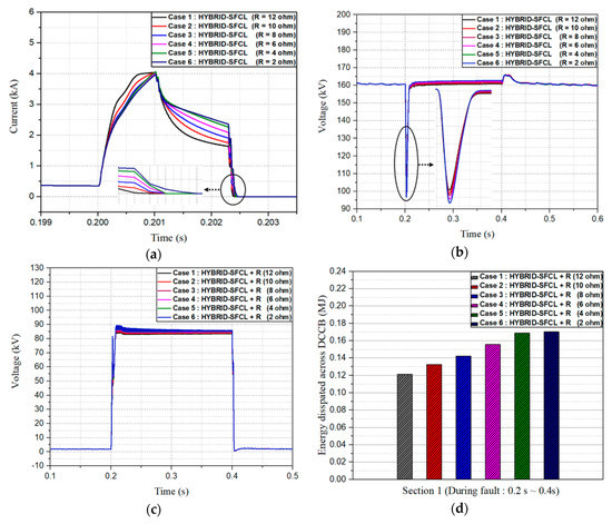
Figure 18.
The DC current and voltage waveform in transient state in protection scheme (Case 3): (a) current waveform in fault period; (b) voltage waveform in transient state; (c) voltage waveform across DCCB; (d) energy dissipation across DCCB.
Figure 18b shows the voltage waveform during the fault transient. In the recovery period, the overvoltage value is almost the same, but in the fault period, there is a slight difference in the voltage dip. The larger the resistance component, the smaller the voltage dip will be. Therefore, Case 1 with large resistance can be considered optimal, because the voltage dip affects the power quality of a system and other sensitive electronics equipment in various ways based on the dip characteristic.
As shown in Figure 18c, the voltage stress across the circuit breaker was also found to be lower as the resistance component was increased. Figure 18d shows that the energy dissipation across the circuit breaker varies with the resistance component. Case 1, which has the greatest resistance, showed an energy dissipation of 0.12 (MJ), while it showed a 41% increase of 0.17 (MJ) for Case 6 with the least resistance.
As a result, when applying the protection scheme for HVDC grid, design with the minimum reactance that can allow the circuit breaker operation time and maximum resistance component will satisfy the requirement of optimum design.
7. Conclusions
Three types of representative protection schemes composed of SFCL and DCCB have been investigated for the feasibility of application in an HB-MMC HVDC grid. The maximum fault interruption time, rate of rise of fault current, energy dissipation across protection devices, and voltage characteristics of the system during the transient period have been compared.
A protection scheme with R-SFCL and DCCB has a relatively compact structure and offers satisfactory fault interruption characteristics. However, it showed severe limitation in terms of energy dissipation, maximum AC and DC overvoltage during reclosing. Furthermore, the long recovery time of the SFCL can become an impediment in satisfying the fast reclosing requirements of the HB-MMC HVDC grid.
On the other hand, a protection scheme with SI-SFCL and DCCB exhibited the satisfactory fault current interruption characteristics and the low AC and DC overvoltage in the reclosing period. In addition, it has ultra-fast recovery characteristics. Therefore, when this protection scheme is applied in the HB-MMC HVDC grid, it can satisfy the requirements of fast reclosing and protection coordination. Nevertheless, since there is a large reactance component even after the main breaker operation, the fault current decreased rather slowly. This has a detrimental effect on interruption time and energy dissipation.
The novel Hybrid-SFCL is designed to overcome the abovementioned drawbacks while maintaining the advantages of SI-SFCL. Protection scheme based on Hybrid-SFCL and DCCB performs limiting operation by its resistance and reactance component after the operation of main breaker. The fault current decreases quite rapidly. It was confirmed that the protection scheme has many advantages in terms of fault interruption, the SFCL recovery, energy dissipation, insulation stress, and DC grid restoration despite a disadvantage related to conduction loss in the normal state.
As a result, it is expected that the protection scheme with the Hybrid-SFCL would be the likely candidate for application in future HVDC grids due to its low interruption time, low overvoltage magnitude, energy dissipation across DCCB and small recovery time to satisfy the restoration requirement. Furthermore, it is beneficial in terms of insulation design because relatively low overvoltage stress is applied to various power system components during transient period. Finally, for application in HVDC grid, the protection system will be considered optimal if it can allow sufficient operation time to the circuit breaker with minimum reactance and maximum resistance component.
For a future work, we are planning to compare experiment results based on the scaled model of the three types of protection schemes. The development of the scaled model of the system is underway in this regard.
Author Contributions
H.-Y.L. conceptualized the topic, formulated methodology, performed simulations, and prepared an original draft; M.A. performed a formal analysis and reviewed the draft; K.-H.P. and H.-M.M. curated the data and edited the draft; B.-W.L. supervised the study.
Funding
This research received no external funding.
Acknowledgments
This work was supported by the Ministry of Trade, Industry, and Energy of Korea through the Human Resources Program in Energy Technology of the Korea Institute of Energy Technology Evaluation and Planning (KETEP) under Grant 20174030201780 and by the KEPCO Research Institute under the project entitled by “Design of analysis model and optimal voltage for MVDC distribution system (R17DA10)”.
Conflicts of Interest
The authors declare no conflict of interest.
References
- An, T.; Tang, G.; Wang, W. Research and application on multi-terminal and DC grids based on VSC-HVDC technology in China. High Volt. 2017, 2, 1–10. [Google Scholar] [CrossRef]
- Li, B.; He, J.; Tian, J.; Feng, Y.; Dong, Y. DC fault analysis for modular multilevel converter-based system. J. Mod. Power Syst. Clean Energy 2017, 5, 275–282. [Google Scholar] [CrossRef]
- Wang, P.; Zhang, X.P.; Coventry, P.F.; Zhang, R.; Li, Z. Control and protection sequence for recovery and reconfiguration of an offshore integrated MMC multi-terminal HVDC system under DC faults. Int. J. Electr. Power Energy Syst. 2017, 86, 81–92. [Google Scholar] [CrossRef]
- Rodriguez, J. Multilevel converters: An enabling technology for high-power applications. Proc. IEEE. 2009, 97, 1791–1792. [Google Scholar] [CrossRef]
- Lee, H.Y.; Asif, M.; Park, K.H.; Lee, B.W. Assessment of appropriate SFCL type considering DC fault Interruption in Full Bridge Modular Multilevel Converter HVDC system. Phys. C Supercond. Its Appl. 2019, 563, 1–6. [Google Scholar] [CrossRef]
- Chen, X.; Zhao, C. Research on the fault characteristics of HVDC based on modular multilevel converter. In Proceedings of the 2011 IEEE Electrical Power and Energy Conference, Winnipeg, MB, Canada, 3–5 October 2011. [Google Scholar]
- Jonsson, T.; Lundberg, S. Converter Technologies and Functional Requirements for Reliable and Economical HVDC Grid Design. In Proceedings of the 2013 CIGRE Canada Conference, Calgary, AB, Canada, 9–11 September 2013. [Google Scholar]
- Najmi, V. Modelling, Control and Design Considerations for Modular Multilevel Converters. Master’s Thesis, Electrical Engineering Department, Virginia Polytechnic Institute and State University, Blacksburg, VA, USA, May 2015. [Google Scholar]
- Adam, G.P.; Williams, B.W. Half-and full-bridge modular multilevel converter models for simulations of full-scale HVDC links and multiterminal DC grids. IEEE J. Emerg. Sel. Top. Power Electron. 2014, 2, 1089–1108. [Google Scholar] [CrossRef]
- Xu, Z.; Xiao, H.; Xiao, L.; Zhang, Z. DC fault analysis and clearance solutions of MMC-HVDC systems. Energies 2018, 11, 941. [Google Scholar] [CrossRef]
- Franck, C.M. HVDC circuit breakers: A review identifying future research needs. IEEE Trans. Power Deliv. 2011, 26, 998–1007. [Google Scholar] [CrossRef]
- Pei, X.; Cwikowski, O.; Smith, A.C.; Barnes, M. Design and Experimental Tests of a Superconducting Hybrid DC Circuit Breaker. IEEE Trans. Appl. Supercond. 2018, 28, 5000205. [Google Scholar] [CrossRef]
- Song, Q.; Zeng, R.; Yu, Z.; Liu, W.; Huang, Y.; Yang, W.; Li, X. A modular multilevel converter integrated with DC circuit breaker. IEEE Trans. Power Deliv. 2018, 33, 2502–2512. [Google Scholar] [CrossRef]
- Zhang, L.; Shi, J.; Wang, Z.; Tang, Y.; Yang, Z.; Ren, L.; Yan, S.; Liao, Y. Application of a Novel Superconducting Fault Current Limiter in a VSC-HVDC System. IEEE Trans. Appl. Supercond. 2017, 27, 5600706. [Google Scholar] [CrossRef]
- Mokhberdoran, A.; Carvalho, A.; Silva, N.; Leite, H.; Carrapatoso, A. Application study of superconducting fault current limiters in meshed HVDC grids protected by fast protection relays. Electr. Power Syst. Res. 2017, 143, 292–302. [Google Scholar] [CrossRef]
- Chen, L.; He, H.; Li, G.; Chen, H.; Wang, L.; Chen, X.; Tian, X.; Xu, Y.; Ren, L.; Tang, Y. Study of resistive-type superconducting fault current limiters for a hybrid high voltage direct current system. Materials (Basel) 2018, 12, 26. [Google Scholar] [CrossRef] [PubMed]
- Chen, L.; Tu, X.; Chen, H.; Yang, J.; Wu, Y.; Shu, X.; Ren, L. Technical evaluation of superconducting fault current limiters used in a micro-grid by considering the fault characteristics of distributed generation, energy storage and power loads. Energies 2016, 9, 769. [Google Scholar] [CrossRef]
- Lee, H.Y.; Asif, M.; Park, K.H.; Lee, B.W. Feasible Application Study of Several Types of Superconducting Fault Current Limiters in HVDC Grids. IEEE Trans. Appl. Supercond. 2018, 28, 5601205. [Google Scholar] [CrossRef]
- Bock, J.; Hobl, A.; Schramm, J.; Kramer, S.; Janke, C. Resistive superconducting fault current limiters are becoming a mature technology. IEEE Trans. Appl. Supercond. 2015, 25, 5600604. [Google Scholar] [CrossRef]
- Jiang, L.; Jin, J.X.; Chen, X.Y. Fully Controlled Hybrid Bridge Type Superconducting Fault Current Limiter. IEEE Trans. Appl. Supercond. 2014, 24, 5602705. [Google Scholar]
- Morandi, A.; Imparato, S.; Grasso, G.; Berta, S.; Martini, L.; Bocchi, M.; Fabbri, M.; Negrini, F.; Ribani, P.L. Design of a DC resistive SFCL for application to the 20 kV distribution system. IEEE Trans. Appl. Supercond. 2010, 20, 1122–1126. [Google Scholar] [CrossRef]
- Yang, Q.; Le Blond, S.; Liang, F.; Yuan, W.; Zhang, M.; Li, J. Design and Application of Superconducting Fault Current Limiter in a Multiterminal HVDC System. IEEE Trans. Appl. Supercond. 2017, 27, 3800805. [Google Scholar] [CrossRef]
- Leon Garcia, W.R.; Tixador, P.; Raison, B.; Bertinato, A.; Luscan, B.; Creusot, C. Technical and Economic Analysis of the R-Type SFCL for HVDC Grids Protection. IEEE Trans. Appl. Supercond. 2017, 27, 5602009. [Google Scholar] [CrossRef]
- Wei, Z.; Xin, Y.; Jin, J.; Li, Q. Optimized design of coils and iron cores for a saturated iron core superconducting fault current limiter. IEEE Trans. Appl. Supercond. 2016, 26, 5603904. [Google Scholar] [CrossRef]
- Lv, C.; Tai, N.; Jin, Z.; Zheng, X. Research on application of superconducting fault current limiter in MMC-MTDC. J. Eng. 2017, 2017, 1307–1311. [Google Scholar] [CrossRef]
- Ye, L.; Lin, L.Z. Study of superconducting fault current limiters for system integration of wind farms. IEEE Trans. Appl. Supercond. 2010, 20, 1233–1237. [Google Scholar]
- Aly, M.M.; Mohamed, E.A. Comparison between resistive and inductive superconducting fault current limiters for fault current limiting. In Proceedings of the ICCES 2012: 2012 International Conference on Computer Engineering and Systems, Cairo, Egypt, 27–29 November 2012. [Google Scholar]
- Chen, Y.; Liu, X.; Sheng, J.; Cai, L.; Jin, Z.; Gu, J.; An, Z.; Yang, X.; Hong, Z. Design and Application of a Superconducting Fault Current Limiter in DC Systems. IEEE Trans. Appl. Supercond. 2014, 24, 5601305. [Google Scholar] [CrossRef]
- Schmitt, H. Fault current limiters report on the activities of CIGRE WG A3.16. In Proceedings of the 2006 IEEE Power Engineering Society General Meeting, Montreal, QC, Canada, 18–22 June 2006. [Google Scholar]
- Mokhberdoran, A.; Leite, H.; Carvalho, A.; Silva, N. A Review on HVDC Circuit Breakers. In Proceedings of the 3rd Renewable Power Generation Conference (RPG 2014), Naples, Italy, 24–25 September 2014. [Google Scholar]
- Zhang, Z.; Xu, Z. Short-circuit current calculation and performance requirement of HVDC breakers for MMC-MTDC systems. IEEJ Trans. Electr. Electron. Eng. 2016, 11, 168–177. [Google Scholar] [CrossRef]
- Lee, H.-Y.; Asif, M.; Park, K.-H.; Lee, B.-W. Assessment of Appropriate MMC Topology Considering DC Fault Handling Performance of Fault Protection Devices. Appl. Sci. 2018, 8, 1834. [Google Scholar] [CrossRef]
- Acharya, S.; Vechalapu, K.; Bhattacharya, S.; Yousefpoor, N. Comparison of DC fault current limiting capability of various modular structured multilevel converters within a multi-terminal DC grid. In Proceedings of the 2015 IEEE Energy Conversion Congress and Exposition—ECCE 2015, Montreal, QC, Canada, 20–24 September 2015. [Google Scholar]
- Lim, T.C.; Finney, S.J.; Shan, Y.; Williams, B.W. Successful fault current interruption on DC circuit breaker. IET Power Electron. 2016, 9, 207–218. [Google Scholar]
- Zheng, F.; Deng, C.; Chen, L.; Li, S.; Liu, Y.; Liao, Y. Transient performance improvement of microgrid by a resistive superconducting fault current limiter. IEEE Trans. Appl. Supercond. 2015, 25, 5602305. [Google Scholar] [CrossRef]
- Kar, S.; Kulkarni, S.; Dixit, M.; Singh, K.P.; Gupta, A.; Balasubramanyam, P.V.; Sarangi, S.K.; Rao, V.V. Selection criteria of high T c superconducting tapes for superconducting fault current limiter applications. IEEE Trans. Appl. Supercond. 2012, 22, 5602804. [Google Scholar] [CrossRef]
- Kar, S.; Kulkarni, S.; Dixit, M.; Singh, K.P.; Gupta, A.; Balasubramanyam, P.V.; Sarangi, S.K.; Rao, V.V. Study on recovery performance of high Tc superconducting tapes for resistive type superconducting fault current limiter applications. Phys. Procedia 2012, 36, 1231–1235. [Google Scholar] [CrossRef][Green Version]
- Chen, L.; Chen, H.; Shu, Z.; Zhang, G.; Xia, T.; Ren, L. Comparison of Inductive and Resistive SFCL to Robustness Improvement of a VSC-HVDC System with Wind Plants Against DC Fault. IEEE Trans. Appl. Supercond. 2016, 26, 5603508. [Google Scholar] [CrossRef]
- Noe, M.; Steurer, M. High-temperature superconductor fault current limiters: Concepts, applications, and development status. Supercond. Sci. Technol. 2007, 20, R15. [Google Scholar] [CrossRef]
- Amir Khan, U.; Lee, J.G.; Amir, F.; Lee, B.W. A Novel Model of HVDC Hybrid-Type Superconducting Circuit Breaker and Its Performance Analysis for Limiting and Breaking DC Fault Currents. IEEE Trans. Appl. Supercond. 2015, 25, 5603009. [Google Scholar] [CrossRef]
- Sung, B.C.; Park, D.K.; Park, J.W.; Ko, T.K. Study on a series resistive SFCL to improve power system transient stability: Modeling, simulation, and experimental verification. IEEE Trans. Ind. Electron. 2009, 56, 2412–2419. [Google Scholar] [CrossRef]
- Li, B.; Jing, F.; Jia, J.F.; Li, B. Research on Saturated Iron-Core Superconductive Fault Current Limiters Applied in VSC-HVDC Systems. IEEE Trans. Appl. Supercond. 2016, 26, 5603805. [Google Scholar] [CrossRef]
- Sarkar, D.; Roy, D.; Choudhury, A.B.; Yamada, S. Harmonic analysis of a saturated iron-core superconducting fault current limiter using Jiles-Atherton hysteresis model. Model. Meas. Control A 2016, 89, 101–117. [Google Scholar]
- Rhee, S.B.; Lee, J.K.; Lee, B.W. Impacts of superconducting fault current limiters on the recloser operation in distribution electric power systems. IEEE Trans. Appl. Supercond. 2011, 21, 2197–2200. [Google Scholar] [CrossRef]
- Na, J.B.; Kim, Y.J.; Jang, J.Y.; Ryu, K.S.; Hwang, Y.J.; Choi, S.; Ko, T.K. Design and tests of prototype hybrid superconducting fault current limiter with fast switch. IEEE Trans. Appl. Supercond. 2012, 22, 5602604. [Google Scholar]
- Li, B.; Wang, C.; Wei, Z.; Xin, Y.; Li, B.; He, J. Technical Requirements of the DC Superconducting Fault Current Limiter. IEEE Trans. Appl. Supercond. 2018, 28, 5602805. [Google Scholar] [CrossRef]
- Hassanpoor, A.; Hafner, Y.J.; Nami, A.; Vinothkumar, K. Cost-effective solutions for handling dc faults in VSC HVDC transmission. In Proceedings of the 2016 18th European Conference on Power Electronics and Applications, EPE 2016 ECCE Europe, Karlsruhe, Germany, 5–9 September 2016. [Google Scholar]
- Köhler, A. Earth Fault Clearing on an HV DC Transmission Line, with Special Consideration of the Properties of the DC Arc in Free Air. IEEE Trans. Power Appar. Syst. 1967, PAS-86, 298–304. [Google Scholar]
- IEEE Power & Energy Society. IEEE Guide for Automatic Reclosing of Circuit Breakers for AC Distribution and Transmission Lines; IEEE Power & Energy Society: Piscataway, NJ, USA, 2012. [Google Scholar]
- Omicron Electronics Corp. Available online: https://www.omicronenergy.com/download/document/F5363C63-E346-48E9-95DE-0A78861B762F/ (accessed on 10 April 2016).
- Network Protection & Automation Guide. 85-201E. Available online: http://rpa.energy.mn/wp-content/uploads/2016/07/network-protection-and-automation-guide-book.pdf (accessed on 7 April 2019).
© 2019 by the authors. Licensee MDPI, Basel, Switzerland. This article is an open access article distributed under the terms and conditions of the Creative Commons Attribution (CC BY) license (http://creativecommons.org/licenses/by/4.0/).