Interoperability Testing Methodology for Smart Grids and Its Application on a DSM Use Case—A Tutorial


Abstract
:1. Introduction
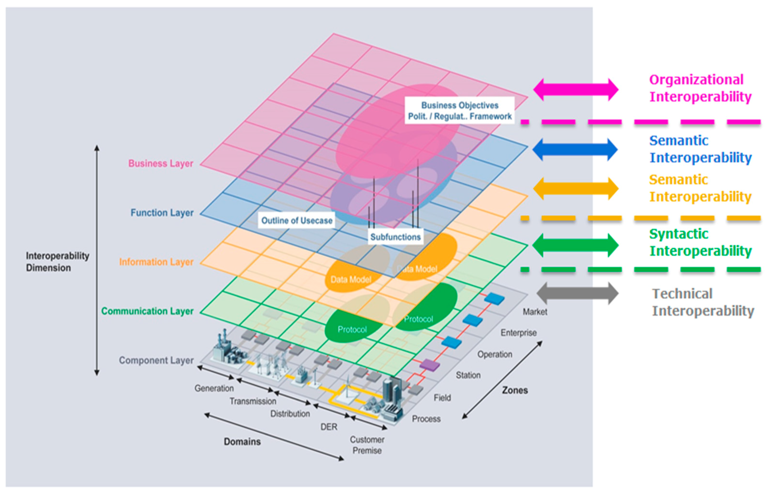
- Business layer which represents the business view on the information (business models, market structures, business portfolios etc.)
- Functional layer specifying the functions and services
- Information layer which is the data model to be used to ensure a common understanding of the data exchanged
- Communication layer which is the communication technology (e.g., PLC or Ethernet) and the communication protocol for data transmission
- Component layer which is the hardware to connect systems or devices such as power cables (physical distribution)
- Demand Response is considered to be a bottom-up approach: the customer is provided with incentives so as to become active in load management and to shift/curtail loads. Such incentives can be convenient tariff schemes or economic benefits in general. In any case, the customer is responsible for managing his/her consumption.
- Demand Side Management is considered a top-down approach: the energy provider/energy service company/aggregator is responsible for reducing or removing peak loads. Such an actor decides on measures to be implemented so as to increase the grid’s stability by shifting or curtailing loads.
- We provide a structured methodology for interoperability testing which can become a valuable tool for researchers and engineers in order to validate the correct operation and exchange of information between different components of the smart grid. The proposed methodology is a complete tool for interoperability testing, which is missing from what already exists in the literature and can be applied in any smart grid interoperability use case.
- The methodology gives the total sequence of steps to be followed, from the use case creation to the test results and statistical analysis and takes into account the SGAM model.
- An example is given that shows how to apply this methodology: a use case is created and the methodology steps are followed for an interoperability test. The test steps are described. Through the given example, the reader can have a clear idea of how to implement the methodology on a smart grid interoperability use case.
- The use case selected for this tutorial is a demand side management use case; it describes the interaction between the energy provider and customer and it involves many actors in the chain from energy provider and end user. This use case gives an insight of how these actors can interact and their depiction on the SGAM gives feedback on the plethora of standards that can be used in each data exchange link.
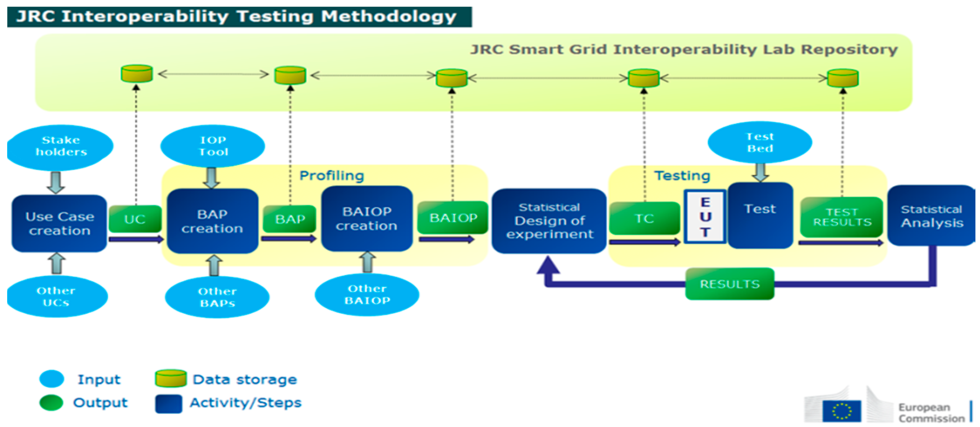
2. Proposed Methodology
- Creation of Use Case with the input from stakeholders
- Profiling by creating Basic Application Profiles and Basic Application Interoperability Profiles
- Testing which includes the test beds, the Equipment Under Test, the Design of the Experiment and of course the IOP testing
- Analysing the results with (possible) feedback to the testing phase for further exploring
- Step 1: Use Case Elaboration
- Step 2: Basic Application Profiles (BAP) creation
- Step 3: Basic Application Interoperability Profiles (BAIOP) creation
- Step 4: Statistical Design of experiments (DoE)
- Step 5: Testing
- Step 6: Statistical Analysis of experiments
3. DSM Use Case
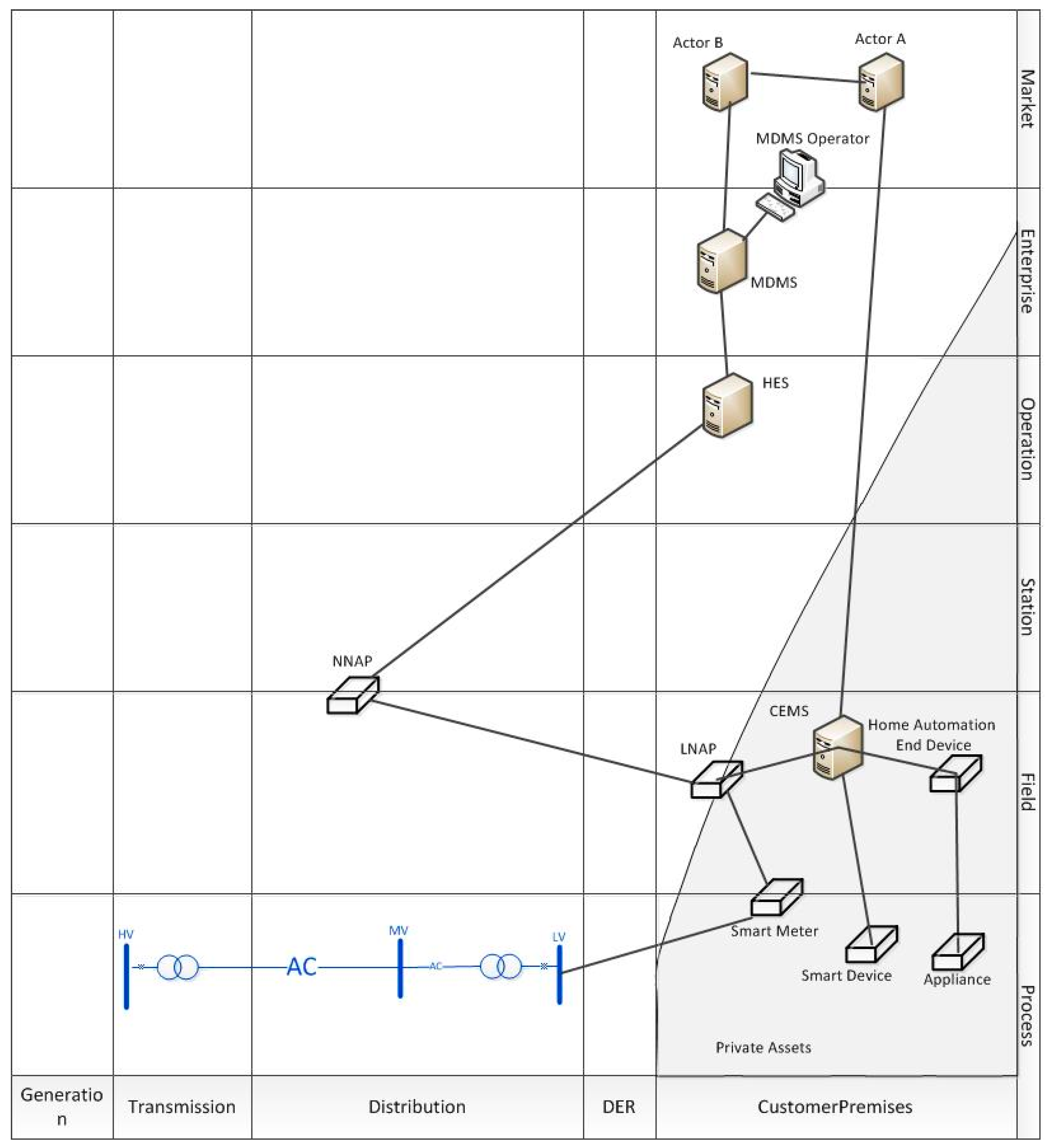
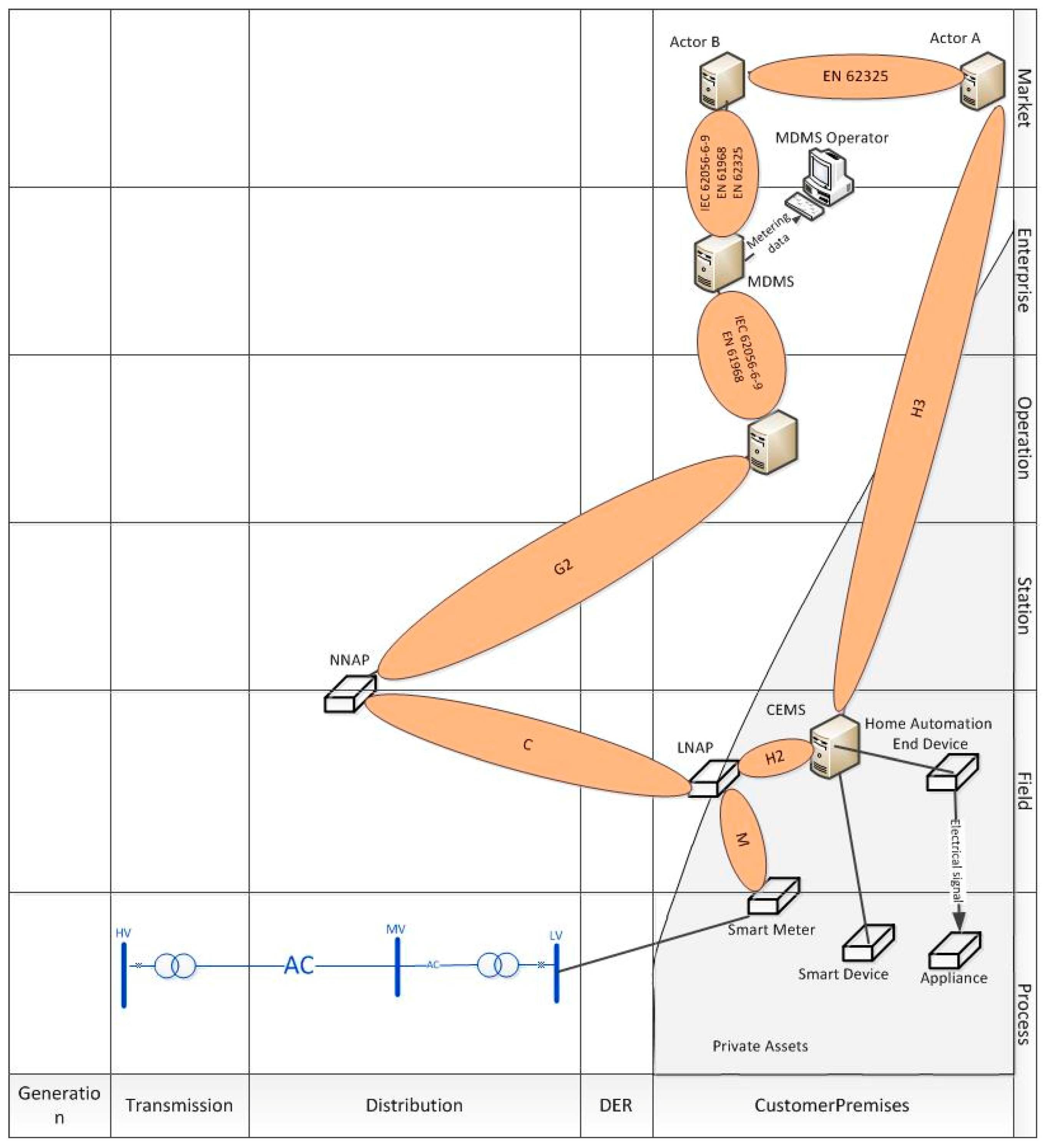
3.1. Use Case Description
3.2. Mapping of Use Case to SGAM Layers
4. Profiling
4.1. Basic Application Profiles for the Examined Use Case
4.2. Basic Application Interoperability Profile for the Examined Use Case
- The smart meter should read consumption of the load;
- The smart meter should communicate with the data concentrator;
- The data should be sent data every 5, 15 or 60 min as defined by the operator;
- The data concentrator should control the new smart meter, be able to change its parameters, be able to get instantaneous values;
- The operator (Actor B) should be able to control and monitor the smart meter through the data concentrator, i.e., get consumption data;
- Specification of equipment under test: technical and operational specification; initial criteria;
- Specification of system under test: description of test bed; description of devices/equipment; technical and operational specifications; configuration; interfaces/communication infrastructure; service access point; description of special equipment (if any); description of software; description of metering and control infrastructure; measuring values;
- Other specifications: ambient conditions; human intervention; staff requirements/training; security aspects;
- EUT ID and BAIOP ID/UC ID
- NamePlate
- Technical Specification
- Operational Specification
- Mounting/cabling/connecting details
- Protection/isolation/earthing information
- Specific safety issues
- Configuration/initial criteria
- Others (based on the EUT)
5. Discussion and Future Work
- The use case description needs to be performed so as to include all actors involved and the mapping on the SGAM needs to be done correctly, otherwise links of interactions may not be included in the further analysis.
- It is essential to define all possible standards that can be used in each link of interaction between actors. At this step, not only is it crucial to define the standard to be used in the link of interest, but also specific options within the standard need to be defined. For example, specific equipment under test can be operating with a specific option of a standard, whereas the rest of the testbed can be operating with a second option of this standard. As a result, the system is theoretically interoperable, but in reality this is not the case. Such an issue can result in inconsistencies and misleading assumptions.
- The step tests need to be precisely defined in the BAIOP creation; otherwise the verdict cannot be derived correctly. Furthermore, the stepwise procedure is a way to breakdown the experiment so that it is better monitored and controlled, the interoperability issues can then more easily tracked.
6. Conclusions
Author Contributions
Funding
Conflicts of Interest
Abbreviations
| AMI | Advanced Metering Infrastructure |
| BAIOP | Basic Application Interoperability Profile |
| BAP | Basic Application Profile |
| CEMS | Customer Energy Management System |
| DDR | Distributed Demand Response |
| DR | Demand Response |
| DoE | Design of Experiments |
| DSM | Demand Side Management |
| DSO | Distribution System Operator |
| EUT | Equipment Under Test |
| ESO | European Standardization Organization |
| JRC | Joint Research Centre |
| HES | Head End System |
| IOP | Interoperability |
| LAN | Local Area Network |
| LN | Local Network |
| LNAP | Local Network Access Point |
| MDMS | Meter Data Management System |
| MSC | Message Sequence Chart |
| NAN | Neighborhood Area Network |
| NNAP | Neighborhood Network Access Point |
| SG-CG | Smart Grid Coordination Group |
| SGAM | Smart Grid Architecture Model |
| SGILab | Smart Grid Interoperability Lab |
| SM | Smart Meter |
| TC | Test Case |
| UC | Use Case |
| WAN | Wide Area Network |
References
- Gungor, V.C.; Sahin, D.; Kocak, T.; Ergut, S.; Buccella, C.; Cecati, C.; Hancke, G.P. Smart grid technologies: Communication technologies and standards. IEEE Trans. Ind. Inform. 2011, 7, 529–539. [Google Scholar] [CrossRef]
- Huh, J.H.; Je, S.M.; Seo, K. Communications-Based Technology for Smart Grid Test Bed Using OPNET Simulations. In Information Science and Applications (ICISA); Kim, K., Joukov, N., Eds.; Lecture Notes in Electrical Engineering; Springer: Singapore, 2016; Volume 376. [Google Scholar]
- Farhangi, H. The path of the smart grid. IEEE Power Energy Mag. 2010, 8, 18–28. [Google Scholar] [CrossRef]
- IEC 61850 Power Utility Automation, IEC Standards. Available online: http://www.iec.ch/smartgrid/standards/ (accessed on 5 September 2018).
- Interoperability Definition, CENELEC. Available online: https://www.cenelec.eu/aboutcenelec/whatwestandfor/societywelfare/interoperability.html (accessed on 5 September 2018).
- Smart Grid Mandate: Standardization Mandate to European Standardisation Organisations (ESOs) to Support European Smart Grid Deployment, DG ENER, European Commission. March 2011. Available online: https://ec.europa.eu/energy/sites/ener/files/documents/2011_03_01_mandate_m490_en.pdf (accessed on 5 September 2018).
- CEN/CENELEC-ETSI Smart Grid Set of Standards Version 4.0. Final October 2016. Available online: https://www.cencenelec.eu/standards/Sectors/SustainableEnergy/SmartGrids/Pages/default.aspx (accessed on 5 September 2018).
- Miswan, N.S.; Ridwan, M.I.; Hayatudin, A.; Musa, I.A. Interoperability testing for Digital Substation in Smart Grid domain: A power utility perspective. In Proceedings of the International Symposium on Technology Management and Emerging Technologies (ISTMET), Langkawai Island, Malaysia, 25–27 August 2015. [Google Scholar]
- Cintuglu, M.H.; Youssef, T.; Mohammed, O.A. Development and Application of a Real-Time Testbed for Multiagent System Interoperability: A Case Study on Hierarchical Microgrid Control. In Proceedings of the IEEE Power & Energy Society General Meeting, Chicago, IL, USA, 16–20 July 2017. [Google Scholar]
- Khan, R.; Mclaughlin, K.; Laverty, D.; Sezer, S. Design and Implementation of Security Gateway for Synchrophasor Based Real-Time Control and Monitoring in Smart Grid. IEEE Access 2017, 5, 11626–11644. [Google Scholar] [CrossRef]
- Song, E.Y.; FitzPatrick, G.J.; Lee, K.B. Smart Sensors and Standard-Based Interoperability in Smart Grids. IEEE Sens. J. 2017, 17, 7723–7730. [Google Scholar] [CrossRef]
- Song, E.Y.; FitzPatrick, G.J.; Lee, K.B.; Gopstein, A.M.; Boynton, P.A. Interoperability testbed for smart sensors in smart grids. In Proceedings of the IEEE Power & Energy Society Innovative Smart Grid Technologies Conference (ISGT), Washington, DC, USA, 19–22 February 2018. [Google Scholar]
- Alaerjan, A.; Kim, D.K.; Ming, H.; Malik, K. Using DDS Based on Unified Data Model to Improve Interoperability of Smart Grids. In Proceedings of the IEEE International Conference on Smart Energy Grid Engineering (SEGE), Oshawa, ON, Canada, 12–15 August 2018. [Google Scholar]
- Chang, K.-H. Interoperable nan standards: A path to cost-effective smart grid solutions. IEEE Wirel. Commun. 2013, 20, 4–5. [Google Scholar] [CrossRef]
- Kim, D.K.; Alaerjan, A.; Lu, L.; Yang, H.; Jang, H. Toward Interoperability of Smart Grids. IEEE Commun. Mag. 2017, 55, 204–210. [Google Scholar] [CrossRef]
- Zhu, J. Communication network for smart grid interoperability. In Proceedings of the IEEE International Conference on Communication Software and Networks (ICCSN), Chengdu, China, 6–7 June 2015. [Google Scholar]
- Papaioannou, I.; Tarantola, S.; Lucas, A.; Kotsakis, E.; Marinopoulos, A.; Ginocchi, M.; Olariaga-Guardiola, M.; Masera, M. Smart Grid Interoperability Testing Methodology; EUR 29416 EN; Publications Office of the European Union: Luxembourg, 2018; ISBN 978-92-79-96855-6. [Google Scholar]
- Sustainable Processes, CEN-CENELEC-ETSI Smart Grid Coordination Group. November 2012. Available online: ftp://ftp.cen.eu/EN/EuropeanStandardization/HotTopics/SmartGrids/Sustainable%20Processes.pdf (accessed on 5 September 2018).
- D3.2 Overall System Requirements and Functional Specifications, Scalable Energy Management Infrastructure for Aggregation of Households (SEMIAH) Project. April 2015. Available online: http://semiah.eu/public-deliverables/ (accessed on 5 September 2018).
- D4.1 Certification Mechanisms to Measure the Confidence and Reliability of the Energy Transactions, P2P SmarTest. August 2016. Available online: http://www.p2psmartest-h2020.eu/deliverables (accessed on 5 September 2018).
- Tsai, S.C.; Tseng, Y.H.; Chang, T.H. Communication-Efficient Distributed Demand Response: A Randomized ADMM Approach. IEEE Trans. Smart Grid 2017, 8, 1085–1095. [Google Scholar] [CrossRef]
- Mhanna, S.; Verbič, G.; Chapman, A.C. A Faithful Distributed Mechanism for Demand Response Aggregation. IEEE Trans. Smart Grid 2016, 7, 1743–1753. [Google Scholar] [CrossRef]
- Kuzlu, M.; Rahman, M.M.; Pipattanasomporn, M.; Rahman, S. Internet-based communication platform for residential DR programmes. IET Netw. 2017, 6, 25–31. [Google Scholar] [CrossRef]
- El-Sebaey, N.; Yousef, M.T.; El-Alayly, A.A. An application of expert system for demand side management. In Proceedings of the Fifth International Conference on Power System Management and Control, London, UK, 17–19 April 2002. [Google Scholar]
- Shinde, P.; Swarup, K.S. Optimal Electric Vehicle charging schedule for demand side management. In Proceedings of the International Conference on Sustainable Green Buildings and Communities (SGBC), Chennai, India, 18–20 December 2016. [Google Scholar]
- Pattanaik, P.A.; Sahoo, N.C.; Mishra, S. Implementation of demand side management using microcontroller and wireless communication. In Proceedings of the Second International Conference on Electrical, Computer and Communication Technologies (ICECCT), Coimbatore, India, 22–24 February 2017. [Google Scholar]
- Paschalidis, I.C.; Li, B.; Caramanis, M.C. Demand-Side Management for Regulation Service Provisioning Through Internal Pricing. IEEE Trans. Power Syst. 2012, 27, 1531–1539. [Google Scholar] [CrossRef]
- Sharma, I.; Bhattacharya, K.; Cañizares, C. Smart Distribution System Operations with Price-Responsive and Controllable Loads. IEEE Trans. Smart Grid 2015, 6, 795–807. [Google Scholar] [CrossRef]
- Mohsenian-Rad, A.H.; Wong, V.W.; Jatskevich, J.; Schober, R.; Leon-Garcia, A. Autonomous demand-side management based on game-theoretic energy consumption scheduling for the future smart grid. IEEE Trans. Smart Grid 2010, 1, 320–331. [Google Scholar] [CrossRef]
- Sondermann, M. Demand Response Interoperability for the Residential European Energy Market. Master’s Thesis, University of Twente, Enschede, The Netherlands, 2017. [Google Scholar]
- Andreadou, N.; Soupionis, Y.; Bonavitacola, F.; Prettico, G. A DSM Test case applied on an end-to-end system, from consumer to energy provider. Sustainability 2018, 10, 935. [Google Scholar] [CrossRef]
- Use Case: Demand Response (DR)—Load Profile Management via Pricing Mechanisms, NIST SG Interaction Use Case Template, DGH ver. 3. 25/8/08. Available online: http://smartgrid.epri.com/UseCases/NIST_SG_Interaction_use_case_DR_load_profile_price-Koch.pdf (accessed on 17 July 2018).
- Use Case: Demand Response (DR)—Load Profile Management via Reliability Based Signals, NIST SG Interaction Use Case Template, DGH ver. 3. 25/08/08. Available online: http://smartgrid.epri.com/UseCases/NIST_SG_Interaction_use_case_DR_load_profile_reliability-Koch.pdf (accessed on 17 July 2018).
- Use Case: Load Management with Dynamic Tariffs, Predictable and Non-Predictable Demand Reduction with Demand Shifting, Shedding and Limiting and/or On-Site Generation Capability without Local Resource Optimization, NIST SG Function Description and Use Case Template, DGH ver. 2 (Building-Centric View of Smart Grid). Available online: http://smartgrid.epri.com/UseCases/NIST_SG_Load_Management_Sila.pdf (accessed on 17 July 2018).
- Use Case: Demand Response—Utility Commanded Load Control. Available online: http://smartgrid.epri.com/UseCases/DemandResponse-UtilityCommandedLoadControl.pdf (accessed on 17 July 2018).
- Green, B.D. Demand Response—Direct Load Control Event, American Electric Power (AEP). Available online: http://smartgrid.epri.com/UseCases/Direct%20Load%20Control%20Event_ph2add.pdf (accessed on 17 July 2018).
- The Utility Use Case #3: Customer (Residential and Commercial) Implements Demand Response System and Responds to Demand Response Signals from the Utility (Using AMI), Version 1.11. Available online: http://smartgrid.epri.com/UseCases/UC-3%20Version%201.11.pdf (accessed on 17 July 2018).
- Schleichter, B. Demand Response HAN Device Provisioning, American Electric Power (AEP). Available online: http://smartgrid.epri.com/UseCases/DR%20HAN%20Device%20Provisioning_ph2add.pdf (accessed on 17 July 2018).
- Razzak, M.I. DR HAN Pricing & Event Customer Opt-Out, American Electric Power (AEP). Available online: http://smartgrid.epri.com/UseCases/DR%20HAN%20Pricing%20and%20Event%20Customer%20Opt_ph2add.pdf (accessed on 17 July 2018).
- CEN-CENELEC-ETSI Smart Grid Coordination. SG-CG/M490/I_Smart Grid Interoperability Methodologies to facilitate Smart Grid system interoperability through standardization, system design and testing. 2014. Available online: ftp://ftp.cencenelec.eu/EN/EuropeanStandardization/HotTopics/SmartGrids/SGCG_Interoperability_Report.pdf (accessed on 5 September 2018).
- Smart Grid Reference Architecture. CEN-CENELEC-ETSI Smart Grid Coordination Group. 2012. Available online: ftp://ftp.cencenelec.eu/EN/EuropeanStandardization/HotTopics/SmartGrids/Reference_Architecture_final.pdf (accessed on 5 September 2018).
- CEN/CENELEC-ETSI Functional Reference Architecture for Communications in Smart Metering Systems. Available online: ftp://ftp.cen.eu/cen/Sectors/List/Measurement/Smartmeters/CENCLCETSI_TR50572.pdf (accessed on 5 September 2018).


| Actor Name Selection List | Actor Type | Actor Description, [18] | Further Information Specific to This Use Case |
|---|---|---|---|
| Actor A | External Actor | External actor (Smart Grid Market Role) interacting with the system functions and components in the home or home automation network through the energy management communication channel. Examples of such market roles are the Energy Provider, the Energy Services Provider, the aggregator, etc. | In this UC the external actor can be an energy service company or an aggregator |
| Actor B | External Actor | External actor (Smart Grid Market Role) interacting with the system functions and components in the home or home automation network through the metering communication channel. This actor is responsible for collecting metering data. Examples of such market roles are the DSO, metering company, etc. | In this UC the external actor is the energy provider |
| Meter Data Management System (MDMS) | System | System for validating, storing, processing and analysing large quantities of meter data | |
| Meter Data Management System (MDMS) Operator | Person | Operator of the MDMS System | |
| Head End System (HES) | System | Central Data System collecting data via the AMI of various meters in its service area. It communicates via a WAN directly to the meters and/or to the NNAP or LNAP | |
| Neighbourhood Network Access Point (NNAP) | System | The Neighbourhood Network Access Point is a functional entity that provides access to one or more metering end devices, displays and home automation end devices connected to the neighbourhood network (NN). | In this UC the Data Concentrator is considered as a NNAP |
| Local Network Access Point (LNAP) | System | The Local Network Access Point is a functional entity that provides access to one or more metering end devices, displays and home automation end devices connected to the local network (LN). It may allow data exchange between different functional entities connected to the same LN. | The LNAP can be integrated in the smart meter |
| Smart meter (SM) | System | The metering end device is a combination of the following meter-related functions from the Smart Metering reference architecture:
| |
| Consumer Application | Application | Application that allows the interaction and the information flow between the customer and the Actor A. | |
| Home Customer | Role | A residential consumer of electricity (including also agriculture users) may also be involved in contract-based DR/DSM. | The Home customer in this Use Case decides whether or not to participate in the DR/DSM program |
| Customer Energy Management System (CEMS) | System | Energy management system for energy customers to optimize the utilisation of energy according to supply contracts or other economic targets. Is responsible for gathering flexibilities within the customer premises and providing them to an aggregator, and therefore does not directly participate in flexibility markets. | |
| Smart Device | External Actor | Smart device may be an appliance, generator or storage device (Local storage devices include direct and functional electricity storages such as electrochemical batteries, heat pumps and micro CHP such as fuel cells with heat buffers, air conditioning and cooling devices with thermal inertia, etc.…). The smart device can receive data directly from the grid, though an interface with the CEM and can react to commands and signals from the grid in an intelligent way. | |
| Home automation end device | System | Device providing additional functionalities enabling consumers to interact with their own environment. | |
| Appliance(s) | System | Object device(s) |
| Function Name: | Load Management Based on Demand Response/Demand Side Management | |||||
|---|---|---|---|---|---|---|
| Step No. | Event | Description of Process/Activity | Information Producer | Information Receiver | Information Exchanged | Technical Requirements |
| 1 | SM sends metering data to LNAP | The smart meter forwards the metering data to the LNAP (smart metering gateway) | SM | LNAP | Metering data | - |
| 2 | LNAP sends metering data to NNAP | The LNAP (smart metering gateway) forwards the data to the NNAP (data concentrator) | LNAP | NNAP | Metering data | - |
| 3 | NNAP sends metering data to HES | The NNAP forwards the metering data to the HES (Head End System) | NNAP | HES | Metering data | - |
| 4 | HES sends metering data to MDMS | The HES forwards the metering data to the MDMS (Meter Data Management System) | HES | MDMS | Metering data | - |
| 5 | The MDMS Operator gathers the aggregated metering data from the MDMS | The MDMS gathers data from smart meters for a specific time duration. Then the data is processed by the MDMS Operator to extract consumption user profiles. | MDMS | MDMS Operator | Extraction of the end-users consumption profiles | - |
| 6 | Actor B receives information about the consumption of the end-users | Data is sent to Actor B about the consumption profiles of the end-users. | MDMS | Actor B | Extraction of the end-users consumption profiles | - |
| 7 | Actor A receives information about the end-users consumption profiles | Data is sent to Actor A about the consumption profiles of the end-users | Actor B | Actor A | End-users consumption profiles | - |
| 8 | Actor A sends feedback to the consumer application | Actor A sends information about the user consumption profile and invites the customer to participate in the DR/DSM program | Actor A | Consumer Application | Feedback to the customer | - |
| 9 | Customer gets informed about the consumptions | Customer receives information about the daily consumptions from Actor A through the consumer application and gets invited to participate in the DR/DSM program | Consumer Application | Customer | Feedback to the customer | - |
| 10 | Customer sends information about participating in the DR/DSM program | Customer sends feedback about participation in the DR/DSM program | Customer | Consumer Application | Feedback from the customer | - |
| 11 | Actor A gets feedback from customer | Actor A gets informed about the customer’s intention in participating in the DR/DSM program through the consumer application | Consumer Application | Actor A | Feedback from the customer | - |
| 12 | Actor A interacts with the Customer Energy Management System (CEMS) | Actor A sends load management data to the CEMS | Actor A | Customer Energy Management system (CEMS) | Load Management Data | - |
| 13 | CEMS interacts with the smart device(s) | CEMS sends load management data to the smart device(s) | CEMS | Smart Device | Load Management Data | - |
| 14 | CEMS interacts with the Home Automation End Device | CEMS sends load management data to the Home Automation End Device | CEMS | Home Automation End Device | Load Management Data | - |
| 15 | Home Automation End-Device controls the appliances | The Home Automation End-Device sends load management data to the appliance(s) | Home Automation End- Device | Appliance | Load Management Data | - |
| 16 | The smart meter gets new readings from the appliances | The smart meter gets the new readings from the appliances | Appliance | Smart Meter | Meter Readings | - |
| 17 | The smart meter gets new readings from the smart device(s) | The smart meter gets the new readings from the smart device(s) | Smart Device | Smart Meter | Meter Readings | - |
| 18 | SM sends new metering data to LNAP | The smart meter sends new metering data to the LNAP | SM | LNAP | Metering data | - |
| 19 | LNAP sends new metering data to NNAP | The LNAP forwards the new metering data to the NNAP | LNAP | NNAP | Metering data | - |
| 20 | NNAP sends new metering data to the HES | The NNAP forwards the new metering data to the HES | NNAP | HES | Metering data | - |
| 21 | HES sends new metering data to the MDMS | The HES forwards the new metering data to the MDMS | HES | MDMS | Metering data | - |
| 22 | The MDMS Operator gathers the new aggregated metering data from the MDMS | The MDMS gathers data from smart meters for a specific time duration. Then the data is processed by the MDMS Operator to extract consumption user profiles. | MDMS | MDMS Operator | Extraction of the end-users new consumption profiles | - |
| 23 | Actor B receives new information about the consumption of the end-users | Data is sent to Actor B about the consumption profiles of the end-users. | MDMS | Actor B | Extraction of the end-users new consumption profiles | - |
| 24 | Actor A receives new information about the end-users consumption profiles | Data is sent to Actor A about the consumption profiles of the end-users | Actor A | Actor B | End-users new consumption profiles | - |
| Interface G2—Standard(s) for Information layer |
|---|
| EN 62056-61: Electricity metering—Data exchange for meter reading, tariff and load control—Part 61: Object Identification system |
| EN 62056-62: Electricity metering—Data exchange for meter reading, tariff and load control—Part 62: Interface classes |
| Interfaces C, M—Standard(s) for Information layer |
| EN 62056: Electricity metering—Data exchange for meter reading, tariff and load control |
| Interfaces H2, H3—Standard(s) for Information layer |
| EN 50090-3-3: Home and building electronics systems (HBES)—Part 3.3: Aspects of application—HBES Interworking model and common HBES data types |
| EN 14908: Open Data Communication in Building Automation, Controls and Building Management |
| Interface G2—Communication Layer | |
|---|---|
| Technologies | Relevant Standards |
| GSM/GPRS/EDGE | ETSI EN 301 502; ETSI EN 301 511; ETSI TS 141 101 |
| 3G/WCDMA/UMTS/HSPA | ETSI TS 121 101 |
| LTE/LTE-A, GSM/GPRS/EDGE/3G/WCDMA/UMTS/HSPA | ETSI TS 122 368; ETSI TS 123 682; ETSI TS 129 368 |
| LTE/LTE-A,3G/WCDMA/UMTS/HSPA | ETSI EN 301 908 |
| CDMA2000/UMB | ETSI EN 301 908 |
| LTE/LTE-A | ETSI TS 136 300; ETSI TS 136 201; ETSI TS 136 211; ETSI TS 136 212; ETSI TS 136 213; ETSI TS 136 214; ETSI TS 136 216; ETSI TS 123 401 |
| BB-PLC | ITU-T G.9960; IEEE 1901 |
| Interfaces C and M—Standard(s) for Communication layer |
|---|
| ITU-T G. 9903-2014 Narrowband orthogonal frequency division multiplexing power line communication transceivers for G3-PLC networks |
| ITU-T G.9904-2012 Narrowband orthogonal frequency division multiplexing power line communication transceivers for PRIME networks |
| ITU-T G.9902-2013 Narrowband orthogonal frequency division multiplexing power line communication transceivers for ITU-T G.hnem networks |
| ITU-T G.9901-2014 Narrowband orthogonal frequency division multiplexing power line communication transceivers—Power spectral density specification |
| IEEE 1901.2-2013 Low-Frequency (less than 500 kHz) Narrowband Power Line Communications for Smart Grid Applications |
| ITU-T G.9959: Short range narrow-band digital radio communication transceivers—PHY, MAC, SAR and LLC layer specifications |
| IEEE 802.15.4: 2015 Low-Rate Wireless Networks |
| IEC 61334—Distribution automation using distribution line carrier systems Part 5-1: 2001 Lower layer profiles—The spread frequency shift keying (S-FSK) profile |
| EN 13757 series Communication systems for meters and remote reading of meters |
| ETSI TR 103 908 PowerLine Telecommunications (PLT); BPSK Narrow Band Power Line Channel for Smart Metering Applications |
| CLC TS 50568-4 Electricity metering data exchange—The Smart Metering Information Tables and Protocols (SMITP) suite Part 4: Physical layer based on B-PSK modulation + Data Link Layer |
| EN 14908-Open Data Communication in Building Automation, Controls and Building Management—Control Network Protocol Part 3: Power Line Channel Specification |
| Interfaces H2 and H3—Standard(s) for Communication layer |
|---|
| ITU-T G. 9903-2014 Narrowband orthogonal frequency division multiplexing power line communication transceivers for G3-PLC networks |
| ITU-T G.9904-2012 Narrowband orthogonal frequency division multiplexing power line communication transceivers for PRIME networks |
| ITU-T G.9902-2013 Narrowband orthogonal frequency division multiplexing power line communication transceivers for ITU-T G.hnem networks |
| ITU-T G.9901-2014 Narrowband orthogonal frequency division multiplexing power line communication transceivers—Power spectral density specification |
| IEEE 1901.2-2013 Low-Frequency (less than 500 kHz) Narrowband Power Line Communications for Smart Grid Applications |
| IEEE 802.15.4: 2015 Low-Rate Wireless Networks |
| ITU-T G.9960-2015 Unified high-speed wireline-based home networking transceivers—System architecture and physical layer specification |
| IEEE 1901-2010 Broadband over Power Line Networks: Medium Access Control and Physical Layer Specifications |
| ITU-T G.9959: Short range narrow-band digital radio communication transceivers—PHY, MAC, SAR and LLC layer specifications |
| LoRaWAN Specification 1.0: LoRaWAN™ Specification |
| 3GPP Release 13 NB-IOT: Narrow Band Internet of Things |
| EN 13321: Open data communication in building automation, controls and building management—Home and building electronic system |
| EN 50090: Home and building electronics systems (HBES) |
| EN 14908: Open Data Communication in Building Automation, Controls and Building Management |
| EN 13757: Communication systems for and remote reading of meters |
| BAP ID | Use Case ID | Standard | Interaction Link between Actors | Interoperability Layer |
|---|---|---|---|---|
| I1 | DSM/DR1 | EN 62056 | NNAP-HES | Information |
| I2 | DSM/DR1 | EN 61968 | HES-MDMS | Information |
| I3 | DSM/DR1 | EN 61968 | MDMS-Actor B | Information |
| I4 | DSM/DR1 | EN 62325 | Actor B-Actor A | Information |
| I5 | DSM/DR1 | EN 50090 | Actor A-CEMS | Information |
| I6 | DSM/DR1 | EN 62056 | Smart meter-LNAP | Information |
| I7 | DSM/DR1 | EN 50090 | LNAP-CEMS | Information |
| C1 | DSM/DR1 | ETSI TS 121 101 | NNAP-HES | Communication |
| C2 | DSM/DR1 | EN 60870-5 | HES-MDMS | Communication |
| C3 | DSM/DR1 | EN 62746 | MDMS-Actor B | Communication |
| C4 | DSM/DR1 | EN 62325 | Actor B-Actor A | Communication |
| C5 | DSM/DR1 | EN 50090 | Actor A-CEMS | Communication |
| C6 | DSM/DR1 | EN 50090 | Smart meter-LNAP | Communication |
| C7 | DSM/DR1 | EN 50090 | LNAP-CEMS | Communication |
| BAP ID | Use Case ID | Standard | Interaction Link between Actors | Interoperability Layer |
|---|---|---|---|---|
| I8a | DSM/DR1 | EN 62056 | LNAP–NNAP | Information |
| C8a | DSM/DR1 | ITU-T G.9903 | LNAP–NNAP | Communication |
| C8b | DSM/DR1 | ITU-T G. 9904 | LNAP–NNAP | Communication |
| C8c | DSM/DR1 | ITU-T G. 9902 | LNAP–NNAP | Communication |
| C8d | DSM/DR1 | ITU-T G.9901 | LNAP–NNAP | Communication |
| C8e | DSM/DR1 | IEEE 1901.2 | LNAP–NNAP | Communication |
| C8f | DSM/DR1 | ITU-T G.9959 | LNAP–NNAP | Communication |
| C8g | DSM/DR1 | IEEE 802.15.4 | LNAP–NNAP | Communication |
| C8h | DSM/DR1 | IEC 61334 | LNAP–NNAP | Communication |
| C8i | DSM/DR1 | EN 13757 | LNAP–NNAP | Communication |
| C8j | DSM/DR1 | ETSI TR 103 908 | LNAP–NNAP | Communication |
| C8k | DSM/DR1 | CLC TS 50568-4 | LNAP–NNAP | Communication |
| C8l | DSM/DR1 | EN 14908 | LNAP–NNAP | Communication |
| BAIOP ID | BAPs ID | USE CASE ID |
|---|---|---|
| IU1 | I1, I2, I3, I4, I5, I6, I7 plus I8 | DSM/DR1 |
| CU1 | C1, C2, C3, C4, C5, C6, C7 plus one out of C8a-C8l | DSM/DR1 |
| Test Case ID | T DSM/DR1 |
| BAIOP ID/ UC ID | CU1/DSM/DR1 |
| Interoperability Layer | Communication |
| Summary of the Test | One new residential smart meter (end-user) is added to the system. The new smart meter has connected loads similar to the rest residential consumption profiles. |
| The new smart meter should be recognised by the data concentrator and communication should be established. As further steps, Actor B should monitor the daily consumption, gather the data and forward it to Actor A. Messages should be sent to the end-user for his/her participation to the DSM/DR program Actor A should control the CEMS within the home. | |
| Test Purpose | To test the integration of a new end-user (new smart meter) in the system. |
| Test Description | |
| Step 1 | The EUT is a new smart meter added to the test bed and connections are done correctly. |
| Step2 | The EUT has connected loads, which function normally, so, energy is flowing without problems. |
| Step 3 | The data concentrator is set to accept packets from the new smart meter; the EUT is configured so as to accept data from the data concentrator. For this purpose, the MAC and/or IP addresses of the two devices are required as well as suitable authorisation (passwords) so as to enable the parameters setup. |
| Step 4 | Test verdict PASS: in case the smart meter is recognised by the data concentrator and listed together with the rest of the smart meters (end-users); the communication between the two devices is established. FAIL: if the smart meter is not recognised by the data concentrator; the communication is not established. |
| Test Case ID | T DSM/DR2 |
| BAIOP ID/ UC ID | IU1/DSM/DR1 |
| Interoperability Layer | Information |
| Summary of the Test | One new residential smart meter (end-user) is added to the system. The new smart meter has connected loads similar to the rest residential consumption profiles. |
| The new smart meter should be recognised by the data concentrator and communication should be established. As further steps, Actor B should monitor the daily consumption, gather the data and forward it to Actor A. Messages should be sent to the end-user for his/her participation to the DSM/DR program Actor A should control the CEMS within the home. | |
| Test Purpose | To test the integration of a new end-user (new smart meter) in the system |
| Test Description | |
| Step 1 | The EUT is a new smart meter added to the test bed and connections are done correctly. |
| Step2 | The EUT has connected loads, which function normally, so, energy is flowing without problems. |
| Step 3 | The data concentrator is set to accept packets from the new smart meter; the EUT is configured so as to accept data from the data concentrator. For this purpose, the MAC and/or IP addresses of the two devices are required as well as suitable authorisation (passwords) so as to enable the parameters setup. |
| Step 4 | The communication between the smart meter and the data concentrator needs to be established: A PASS verdict of the test on the communication layer is required for this interoperability test to proceed. |
| Step 5 | Test Verdict: PASS: in case Actor B can monitor and control the new smart meter; access to its values is available through the software; the interpretation and demonstration of information through the software takes place; the smart meter accepts commands from the data concentrator. FAIL: otherwise. |
© 2018 by the authors. Licensee MDPI, Basel, Switzerland. This article is an open access article distributed under the terms and conditions of the Creative Commons Attribution (CC BY) license (http://creativecommons.org/licenses/by/4.0/).
Share and Cite
Andreadou, N.; Papaioannou, I.; Masera, M. Interoperability Testing Methodology for Smart Grids and Its Application on a DSM Use Case—A Tutorial. Energies 2019, 12, 8. https://doi.org/10.3390/en12010008
Andreadou N, Papaioannou I, Masera M. Interoperability Testing Methodology for Smart Grids and Its Application on a DSM Use Case—A Tutorial. Energies. 2019; 12(1):8. https://doi.org/10.3390/en12010008
Chicago/Turabian StyleAndreadou, Nikoleta, Ioulia Papaioannou, and Marcelo Masera. 2019. "Interoperability Testing Methodology for Smart Grids and Its Application on a DSM Use Case—A Tutorial" Energies 12, no. 1: 8. https://doi.org/10.3390/en12010008
APA StyleAndreadou, N., Papaioannou, I., & Masera, M. (2019). Interoperability Testing Methodology for Smart Grids and Its Application on a DSM Use Case—A Tutorial. Energies, 12(1), 8. https://doi.org/10.3390/en12010008