Article

A Novel Fault-Tolerant Control of Modular Multilevel Converter under Sub-Module Faults Based on Phase Disposition PWM

1
Institute of Electrical Engineering, Chinese Academy of Sciences, Beijing 100044, China
2
National Active Distribution Network Technology Research Center, Beijing Jiaotong University, Beijing 100044, China
*
Author to whom correspondence should be addressed.
Energies 2019, 12(1), 20; https://doi.org/10.3390/en12010020
Submission received: 14 November 2018 / Revised: 10 December 2018 / Accepted: 18 December 2018 / Published: 21 December 2018

Abstract

:
Each arm of modular multilevel converter (MMC) consists of a large number of sub-module (SM) units. However, it also increases the probability of SM failure during the long-term system operation. Focusing on the fault-tolerant operation issue for the MMC under SM faults, the traditional zero-sequence voltage injection fault-tolerant control algorithm is analyzed detailed and its disadvantages are concluded. Based on this, a novel fault-tolerant control strategy based on phase disposition pulse-width modulation (PD-PWM) is proposed in this paper, which has three main benefits: (i) it has carrier and modulation wave dual correction mechanism, which control ability is more higher and flexible; (ii) it only needs to inject zero-sequence voltage in half a cycle of the modulation wave, which simplifies the complexity of traditional zero-sequence voltage injection control algorithms and much easier for implement; (iii) furthermore, the zero-sequence voltage can even be avoided injecting under the symmetrical fault conditions. Finally, the effectiveness of the proposed control strategy is verified with the simulation and experiment studies under different fault conditions.

1. Introduction

Compared with the traditional two-level converter, modular multilevel converter (MMC) enjoys the advantage of modular design [1,2], which allows MMC good scalability and facilitates the improvement of voltage level, as well as other advantages as many output levels and good harmonic characteristics. Therefore, in recent years, MMC topology converters have been widely studied and applied in high-voltage direct current transmission (HVDC), staticsynchronous compensator (STATCOM), and medium-voltage motor drive [3,4,5,6].
In actual transmission projects, in order to adapt to higher transmission voltage level, a large number of sub-modules (SMs) are often cascaded. For example, Trans Bay Cable Project is reported to have 216 SMs per arm [7], and the Zhou Shan multi-terminal flexible HVDC transmission project completed in 2014 in China is larger cascaded reach 250 SMs per arm [8].
As the number of cascaded SMs increasing, the security risks of MMC converters become larger, where the SM faults are prone to occur. When a SM fault occurs and is not processed in time, it may cause system shutdown and even endanger the security of the power grid [9,10]. Therefore, fault-tolerant control approach under SM faults is a problem that needs to be studied.
Generally, the common fault-tolerant control strategies are often designed based on equipping redundant SMs [8]. According to the operation state of the redundant SMs, two main schemes are developed, which are cold-reserve mode and hot-reserve mode, respectively. For the cold-reserve scheme [11,12], it means that the redundant SMs are all in bypassed state when the system operating normally and will replace the same number of faulty SMs when SMs malfunction. For the hot-reserve scheme [13,14,15], it means that the redundant SMs are all operating identically as the rated SMs. However, there are two further detailed modes under this scheme. We call it hot-reserve mode-a, b, respectively, where hot-reserve mode-a means that simultaneously bypass the same number of faulty SMs in each arm to keep the system strictly symmetrical [13]; and hot-reserve mode-b means that only bypass the faulty SMs [14,15]. Compared to the mode-a, the hot-reserve mode-b scheme can ensure full utilizing of all SMs during normal operation period and can avoid the long changing time for redundant SM capacitors to rated values. Furthermore, some extra healthy SMs may need be bypassed in hot-reserve mode-a, which might induce a greater transient impact on the system when large number of SMs are simultaneously bypassed. Therefore, hot-reserve mode-b is a more preferable redundant option for the MMC since its economic and reliability. However, this scheme also has a potential problem, where the system may operate asymmetric under asymmetrical faults. For ensuring the subsequent stable operation, the corresponding fault-tolerant control approach should be further considered, and this is also what this paper deals with.
Based on the background of hot-reserve mode-b, an energy-balancing-based fault-tolerant control strategy is proposed in [16]. Its main control idea is to increase the SM capacitor voltages on the faulty arms to ensure the energy equalization of each arm, thereby achieving the subsequent balance operation of the system. However, the reference command of the SM capacitor voltage needs to be calculated, and the increased value of SM capacitor voltage will become larger as the number of malfunction SMs increases. The neutral-point shift control method has been applied in the H-bridge cascaded multilevel converter system, which can well solve the problems caused by the module faults [17,18,19,20]. Inspired by this idea, the corresponding neutral-point shift control approaches suitable for the MMC system are researched in [15,21]. With injecting the zero-sequence voltage to modify the modulation waves, the converter line-voltages in the grid side are ensured balanced to maintain the system stable operation under SM faults. The advantage of these methods in [15,21] is that they do not need to adjust the SM capacitor voltages in fault arms. Similar to the methods in [15,21], an improved zero-sequence voltage injection fault-tolerant control strategy is proposed in [22]. It simplifies the calculation process of the required zero-sequence voltage. However, the common shortcoming in [15,16,17,18,19,20,21,22] is that they main only consider one arm occurs SM faults. When the upper and lower arm occur SM faults simultaneously, multiple zero-sequence voltages need to be calculated, which increase the complexity of the control method. It should be further improved.
Aiming at this problem and for better deal with the multiple SM fault conditions, also under the background of the redundant SMs equipped with hot reserve scheme and only bypassing the faulty SMs when SMs malfunction, a novel fault-tolerant control strategy is proposed in this paper. Compared to the current approaches, it has three main benefits: (i) it has carrier and modulation wave dual correction mechanism, which control ability is more higher and flexible; (ii) it only needs to inject zero-sequence voltage in half a cycle of the modulation wave, which simplifies the complexity of traditional zero-sequence voltage injection control algorithms and more easier for implement; (iii) furthermore, the zero-sequence voltage can even be avoided injecting under the symmetrical fault conditions. Finally, the effectiveness of the proposed control strategy is verified with the simulation and experiment studies under different fault conditions.

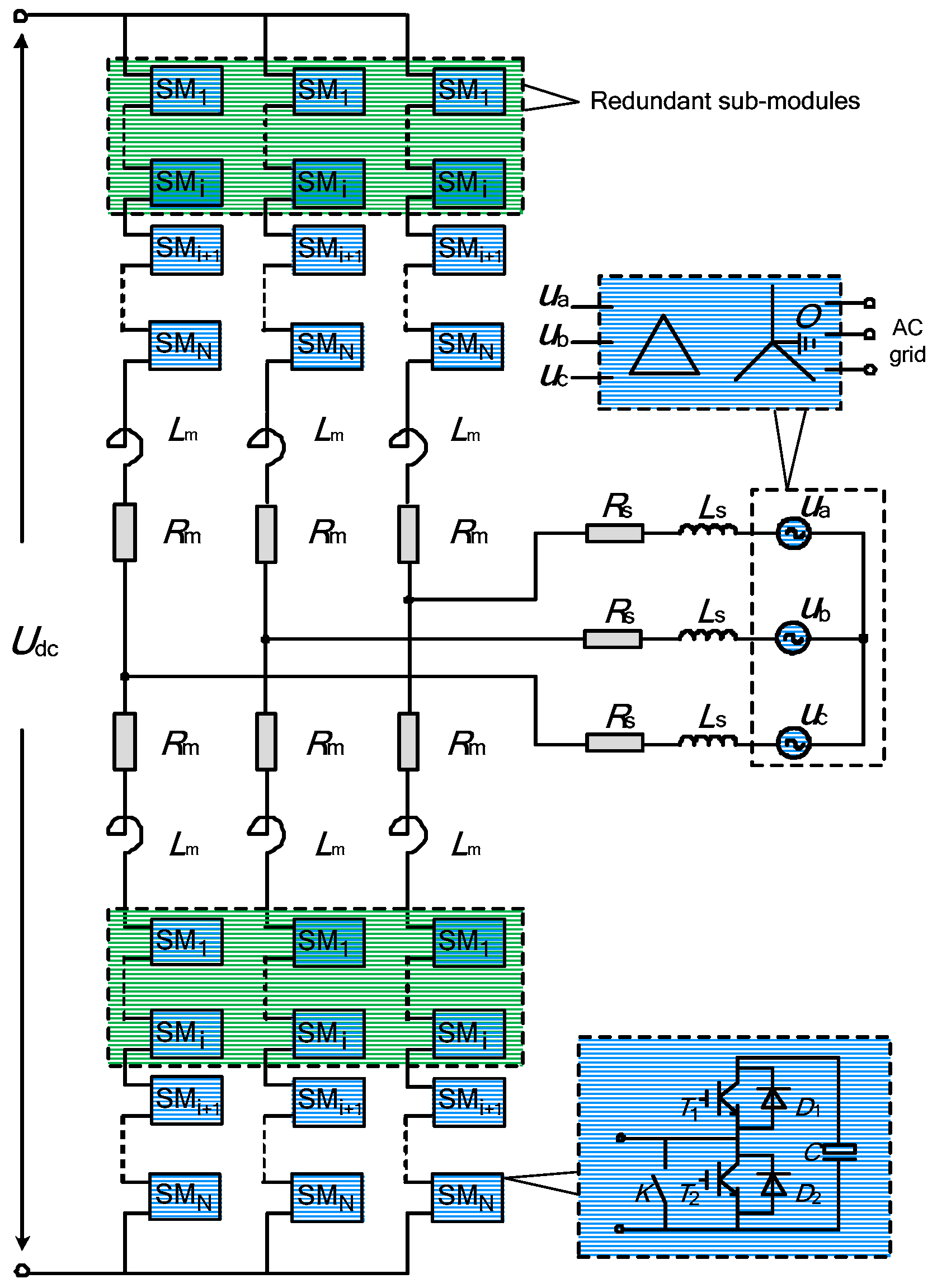
2. Basics Principles of MMC

2.1. MMC Topology

A typical three-phase MMC topology is shown in Figure 1. It consists of six symmetrical arms, which can be divided into three units: phase, arm, and SM. N identical SM units and one arm inductance for suppressing the circulating current and the fault current rising rate are connected in series on each arm, and the AC output terminal is taken out from the midpoint of the upper and lower arm inductances connected to each other. In order to enhance the reliability of the system, there are a certain number of redundant SMs.
Among them, the internal structure of the SM unit has various forms [23,24,25], and the more common half-bridge SM structure is selected as the research object. Specifically, it is composed of an insulated gate bipolar transistor (IGBT) half bridge, a DC capacitor C, and a bypass switch K. In the normal working state of the system, the SM capacitor voltage USM has two levels of output states of 0 and DC capacitor voltage UC. When T1 is turned on and T2 is off, the SM is inserted and outputs UC. When T1 is turned off and T2 is on, the SM is bypassed and output zero. Thus, the AC side multi-level output of the MMC converter can be realized by properly controlling the on-off state of the SM.

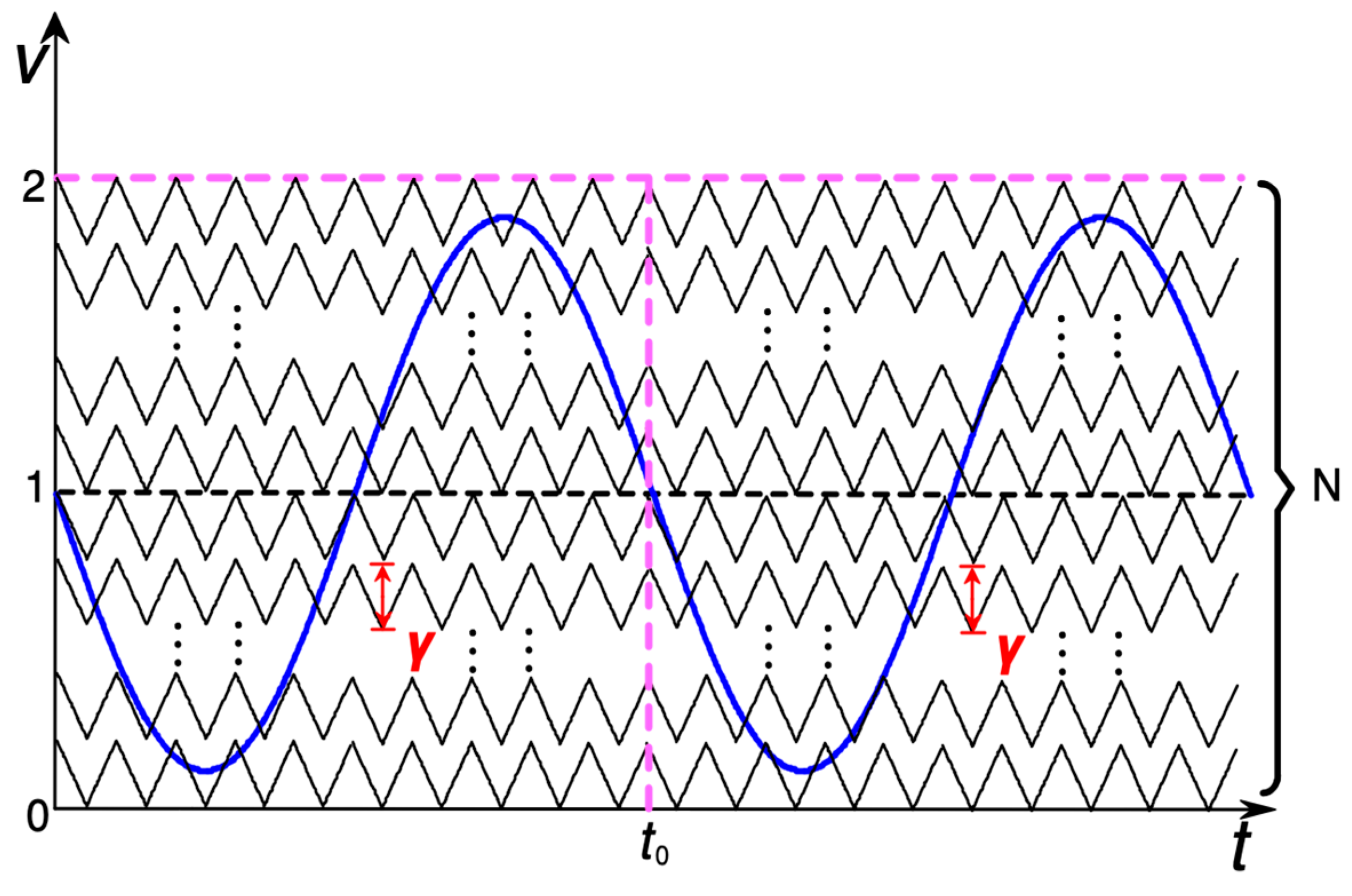
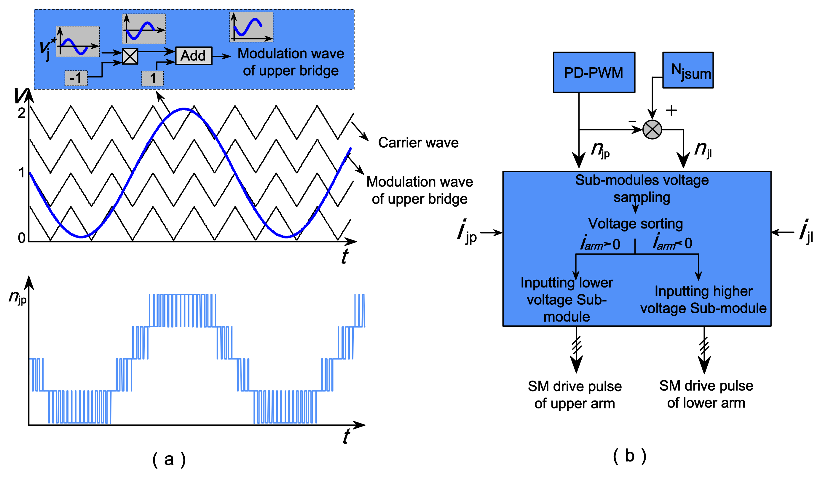
2.2. Phase Disposition PWM and Voltage Balancing Strategy

Currently, MMC’s commonly used modulation methods include carrier phase shift modulation, phase disposition modulation, and nearest level modulation. Because the phase disposition modulation (PD-PWM) method has better harmonic characteristics and is easier to implement [26,27], in this paper, PD-PWM is selected as the basic modulation strategy in subsequent analysis and experiment.
In addition, in order to reduce the fluctuation of SM capacitor voltage, this paper selects the more common capacitor voltage balancing control based on the sorting algorithm [16,28]. The schematic diagram of the relevant control method is shown in Figure 2. Where vj* is the sampled phase voltage of phase j after standard (j = a, b, c). ijp and ijl are the arm current of the upper and lower arm of phase j, respectively. Njsum is the rated total number of the inserted SMs of phase j (i.e., as shown in Figure 1, it is equal to N if no SM faults occur). njp is the number of the SMs need to be inserted in the upper arm of phase j, which is obtained from the PD-PWM modulation. njl is the number of the SMs need to be inserted in the lower arm of phase j, which can be obtained directly by calculating Njsumnjp.
When the system is operating, the numbers of the SMs need to be inserted in the upper arm njp and the lower arm njl are obtained according to the PD-PWM modulation firstly, and then the voltage of each SM in the arm is sorted by the capacitor voltage sorting algorithm. According to the direction of the arm current, the SM with lower capacitor voltage is preferentially charged, and the SM with higher capacitor voltage is preferentially bypassed and discharged, thereby ensuring a relatively balanced voltage of each module during the whole dynamic operation.

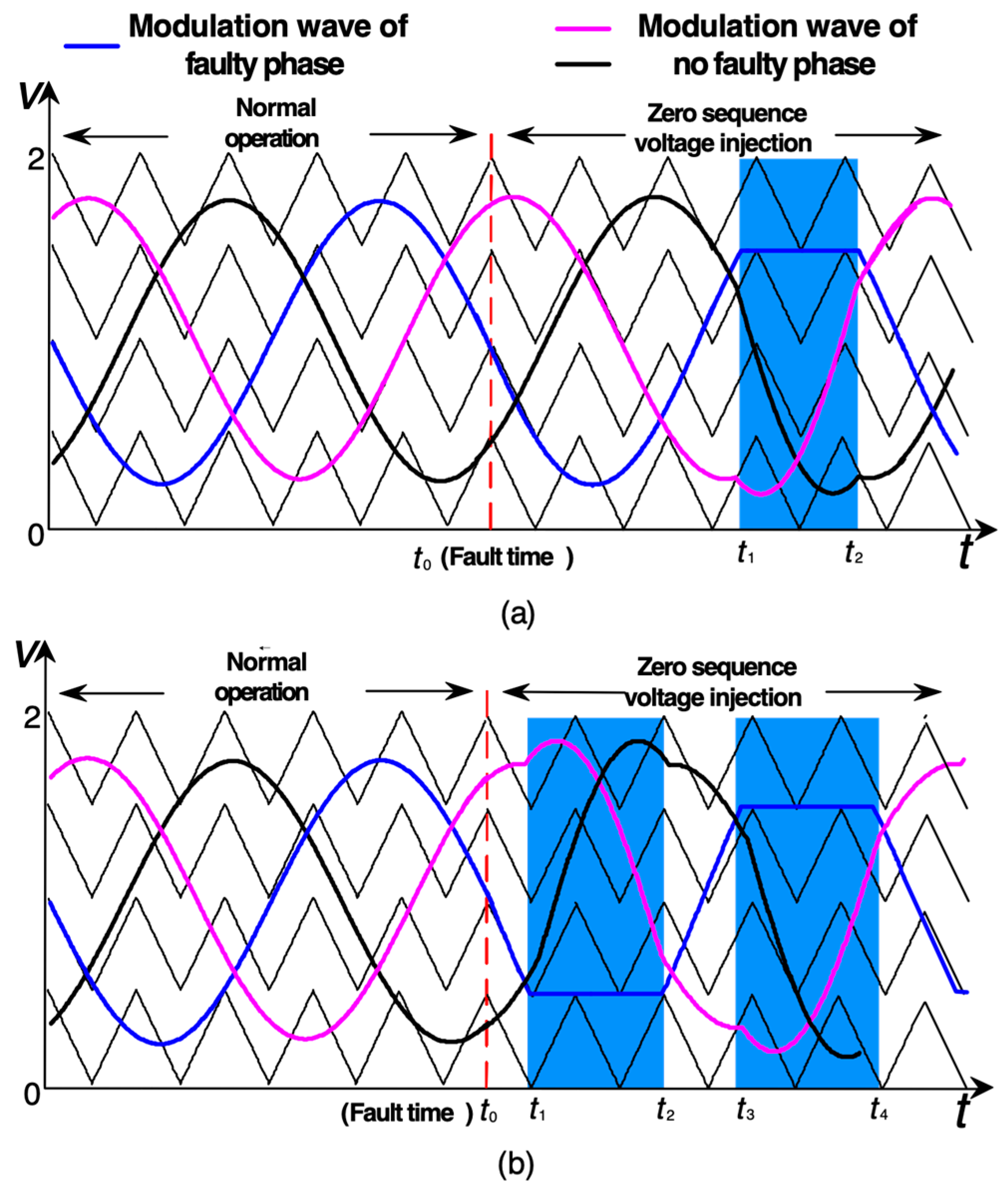
3. Analysis of the Traditional Zero-Sequence Voltage Injection Control Method

After the SM occur faults, it is easy to know that the phase voltage output ability of the fault phase will be changed, and the neutral-point of the phase voltage in the ac side will be offset accordingly. In order to ensure that the MMC converter can continue stable operation with connected to the grid, the zero-sequence voltages can be injected to ensure the line voltage of the MMC converter remains unchanged before and after the SM faults, thereby realizing the fault-crossing of the SM [22]. The basic modulation diagram of the zero-sequence voltage injection control method is shown in Figure 3. Where Figure 3a depicts the schematic diagram of three-phase modulation waves when only the upper arm of phase occur faults, Figure 3b depicts the schematic diagram of three-phase modulation waves when the upper and lower arms of phase j simultaneously occur faults.
With comparing the Figure 3a,b, it can be observed that if the SM faults only occur only in the upper arm, on the basis of bypassing the faulty SMs, the fault-crossing can be realized by only adding one corresponding zero-sequence voltage component on the modulation wave of each phase. It is easy to achieve. However, if the SM simultaneously occur faults in the upper and lower arms, two injected zero-sequence voltages and the four corresponding correction times t1, t1, t1, and t4 are need to be calculated. In addition, if the numbers of the faulty SMs in the upper and lower arms are not identical, the two required zero-sequence voltages are needed to be calculated respectively. This will increase the complexity of the fault-tolerant control algorithm.
Considering that the location and the time of occurring SM faults are random, the MMC might with (i) the signal faulty arm; (ii) the upper and lower symmetrical faulty arms; and (iii) the upper and lower asymmetrical faulty arms after SMs malfunction. Furthermore, the faulty arms state may be re-changed between the mentioned three states when the SMs fault again. Therefore, in order to ensure the stable operation of MMC system and flexibly deal with the multiple possible arms faulty states after SMs malfunction, this paper improves the traditional zero-sequence voltage injection control method, and proposes a new fault-tolerant control strategy based on PD-PWM.

4. Novel Fault-Tolerant Control Strategy

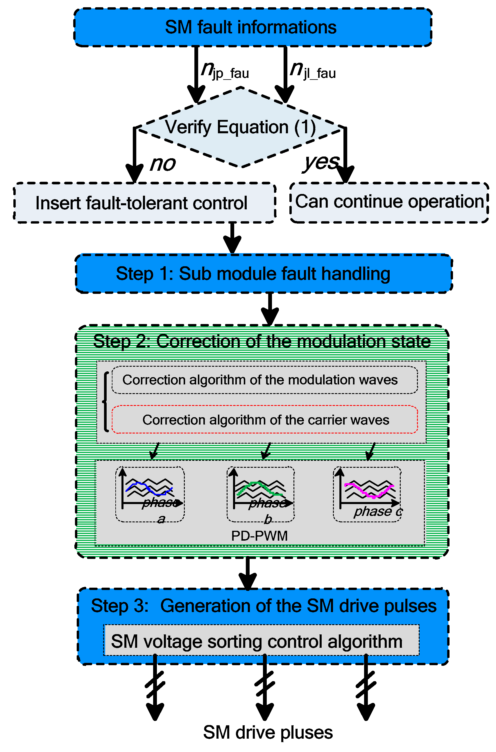
4.1. Overall Control Process of the Proposed Fault-Tolerant Control Strategy

In order to facilitate the later analysis, we define the faulty SM numbers in the upper and lower arms of phase j are njp_fau and njl_fau, respectively. At the same time, we assume the modulation ratio of the system is m under the normal operation. When the number of the faulty SMs in the arm satisfies Equation (1), the fault will not affect the normal operation of the system because of itself modulation margin of the system. While when the Equation (1) is not valid, the fault-tolerant control strategy must be inserted to ensure the subsequent stable operation of the MMC converter.
{ m 1 2 n jp _ fau N m 1 2 n jl _ fau N
Figure 4 shows the overall control flow chart of the fault-tolerant control strategy proposed in this paper. It can be divided into three main parts in the process of implementation:
  • Sub module fault handling. Its main task is to block the trigger pulse of the faulty SMs and isolate the faulty SMs through closing the bypass switch.
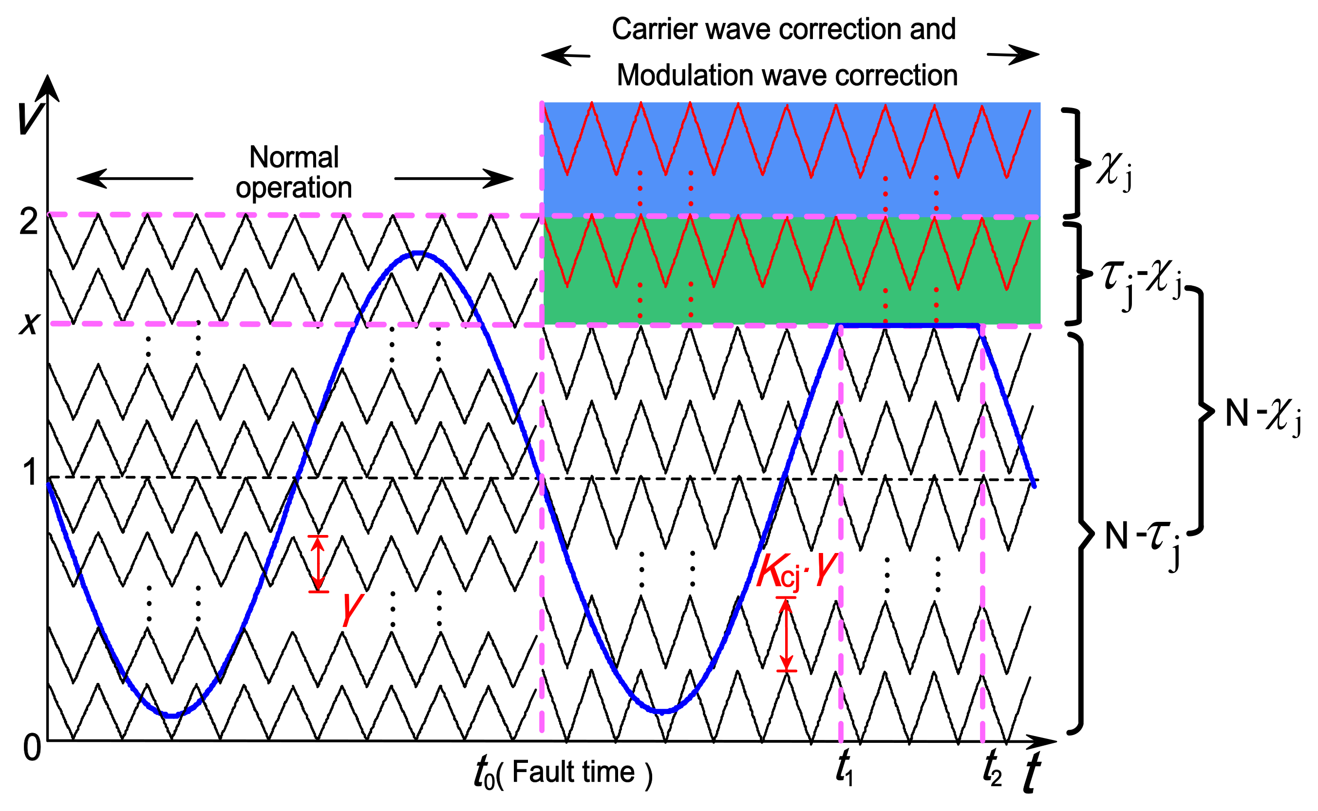
  • Correction of the modulation state. The main task of this part is that with combining the faulty SM numbers of the fault phase, achieving the correction of the original carrier and modulation waves by adopting the proposed correction algorithm (where its specific implementation method will be discussed in detail in Section 4.2, thereby obtaining the SM numbers that need to be inserted in each arms after SMs malfunction.
    In addition, it should be note that this step is the also core part of the fault-tolerant control strategy. In the traditional zero-sequence voltage injection control method, it only with correcting the modulation waves to help achieve the SM fault-crossing. Compared to it, we add the correction algorithm of the carrier waves on the basis of the correction algorithm of the modulation waves, and realized their combination. This effectively simplifies the complexity of traditional control algorithm when deal with multiple arms occurring SM faults.
  • Generation of the SM drive pulses. In this part, with combining the SM numbers that need to be inserted in each arms obtained from the step (2), the drive pulses of the remained healthy SMs are generated by using SM voltage sorting control algorithm, and finally completes the fault-tolerant control.

4.2. Specific Implementation Method of the Correction of the Carrier and Modulation Waves

When the system is operation under the normal state, we can depict the modulation diagram of one phase as Figure 5.
As shown in Figure 5, when the MMC system is operating normally, the carrier waves of the N SMs in the upper arm equally distributed in the interval [0, 2] according to the ratio of γ, where it is easy to know:
γ = 2 N
However, if the SMs occurring faults, the number of SMs that can normally be switched in the faulty phase will be change as the faulty SMs are bypassed. Therefore, the original modulation link must be revised and divided into two parts: ‘Correction algorithm of the carrier waves’ and ‘Correction algorithm of the modulation waves’. We will describe the implementation method detailed in Section 4.2.1 and Section 4.2.2, respectively.

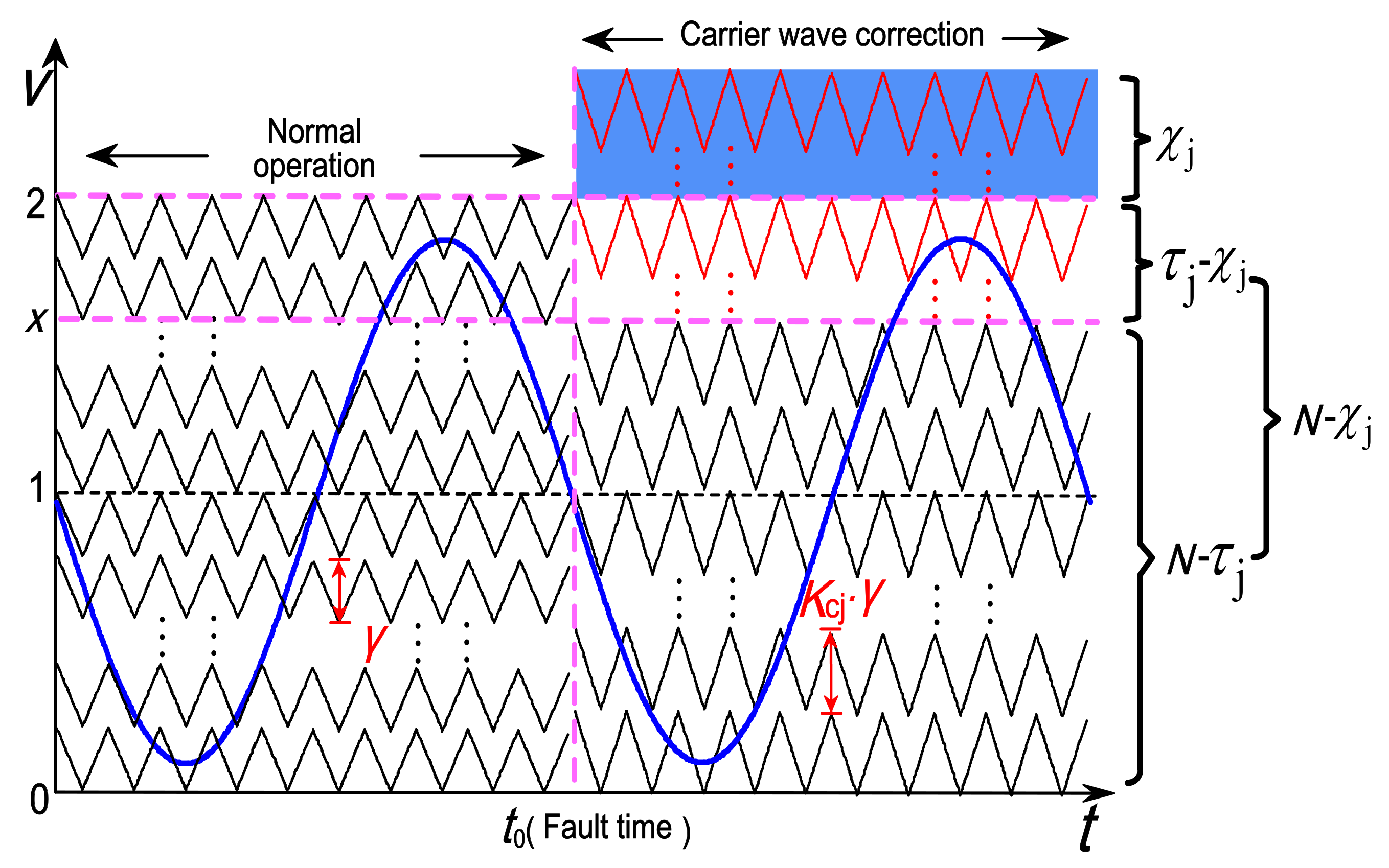
4.2.1. Correction Algorithm of the Carrier Waves

Assuming the SMs occurring faults at t0, and to ensure the generality of the analysis process, supposing the SMs fault in both the upper and lower arms of phase j. Firstly, with comparing the upper arm faulty SM numbers njp_fau and the lower arm faulty SM numbers of njl_fau of phase j, we define the smaller of the two is χj, and the larger of the two is τj. Thereby we obtain:
χ j = min [ n jp _ fau   ,   n jl _ fau ]
τ j = max [ n jp _ fau   ,   n jl _ fau ]
In order to ensure the maximum utilization of the remained healthy SMs, the number of SMs that need to participate in switching operation in the two arms of the fault phase should respectively be:
N j χ = N χ j
N j τ = N τ j
Then, for correcting carrier wave conveniently, the correction coefficient Kjc (Kjc ≥ 1) about the amplitude of the carrier waves is introduced. Simultaneously, combing the smaller faulty SM number χj, we establish a relationship between them, where:
K jc γ = 2 N χ j
Further, we can obtain:
K jc = 2 γ ( N χ j ) = N N χ j
Based on the Equation (8), enlarging the amplitude of the carrier waves with the coefficient Kjc, we can obtain the initially corrected modulation diagram of the faulty phase as shown in Figure 6. It can be observed that the carrier waves in the interval [0, 2] are re-distributed equally according to the ratio of Kjc*γ at this time.
Therefore, through the correction algorithm of the carrier waves, we firstly guarantee the SMs on the smaller faulty SM numbers arm can all normally participate in the switching operation. In other words, we can equivalently consider that the MMC is under the ‘signal arm fault’ state, and its rated SM number is Njχ = Nχj; its faulty SM number is τ jχj. Especially, we can found that when the τjχj = 0 (e.g., the faulty SM numbers in the upper and the lower arm are equal), the SM fault-crossing can be achieved only with the carrier wave correction algorithm.
In addition, if the influence of the different faulty SM numbers τjχj is not considered at present, it can be considered that the fault phase will operate normally according to the newly rated total number of the inserted SMs of phase Njsum = N. Under the control of sorting algorithm, the SM capacitor voltage of the fault phase will automatically be average raised and operating stable [16,28].

4.2.2. Correction Algorithm of the Modulation Waves

As analyzed in the previous section, the faulty phase can be equivalently converted to ‘signal arm fault’ state with the carrier wave correction algorithm. For further eliminating the effects of the different faulty SM numbers τjχj, we establish the modulation wave correction algorithm, where it is achieved by the zero-sequence voltage injection control method.
Firstly, according to the Figure 6, we can calculate:
x = K jc γ ( N τ j ) = 2 N τ j N χ j
Then, according the traditional zero-sequence voltage injection control method [23], the zero sequence voltage that needed to be injected into the initial modulation wave vj* of each phase can be obtained by (9):
k jm ( t ) = v j * + ( x 1 )
Substituting Equations (3), (4) and (9) to (10), we can obtain:
k jm ( t ) = v j * + ( 2 N τ j N χ j 1 ) = v j * + ( 2 N max [ n jp _ fau   ,   n jl _ fau ] N min [ n jp _ fau   ,   n jl _ fau ] 1 )
Based on the Figure 6, injecting the zero-sequence voltage kjm(t) in the interval [t1, t2], we can obtain the final corrected modulation diagram of the faulty phase as shown in Figure 7.
In addition, assuming the sampled phase voltage of phase j after the standard is:
v j * = m sin ( ω t + φ j )
where, φj denotes the initial phase angle of the phase voltage. Combining Equations (9) and (11), the corresponding times t1 and t2 in one modulation period can be calculated respectively:
{ t 1 = arcsin [ ( 1 2 N τ j N χ j ) / m ] φ j ω t 2 = π arcsin [ ( 1 2 N τ j N χ j ) / m ] φ j ω
Based on the above analysis, the overall implementation block diagram of the fault-tolerant control strategy in the MMC system can be obtained as shown in Figure 8.

4.3. Maximum Control Range of the Proposed Control Strategy

Restricting condition 1: meet the voltage pressure requirements. Because when the faulty arm is asymmetric, the carrier wave of each SM will be revised through the increasing carrier wave amplitude control link. At this time, the steady-state operating voltage of the SM will be raised. In order to ensure that the working voltage of the SM is less than the withstand voltage of the SM, it is necessary to satisfy the following requirements:
U dc N χ j < U m
With
min [ n jp _ fau   ,   n jl _ fau ] < N ( 1 U dc U m )
Restricting condition 2: ensure that the system does not appear over modulation. According to the analysis of the previous section, combining the Equations (9)–(13), the set of the modulation amplitudes in the upper arm of each phase in the limiting modulation wave range [t1, t2] can be calculated as follows:
U j * = { 2 N τ j N χ j , 1 m ,   1 + m , ( 1 3 m 2 τ j χ j N χ j )   }
As the system works normally, there must be:
{ 0 m 1 0 χ j < τ j N
Therefore, to ensure that the system does not appear over modulation after the SM fault, it is necessary to ensure that:
0 1 3 m 2 τ j χ j N χ j 2
with
max [ n jp _ fau   ,   n jl _ fau ] 1 3 m 2 N 1 + 3 m 2 χ j

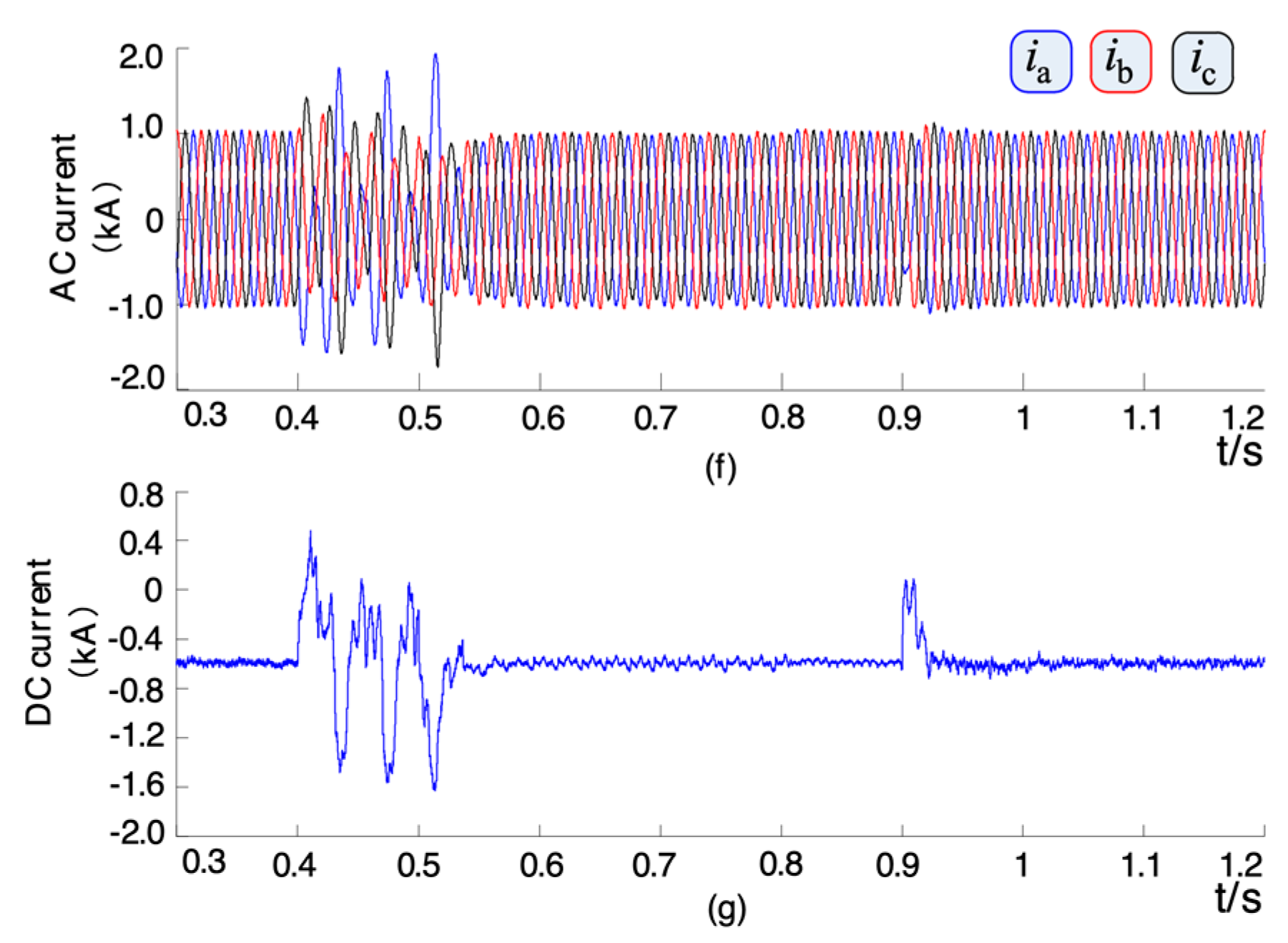
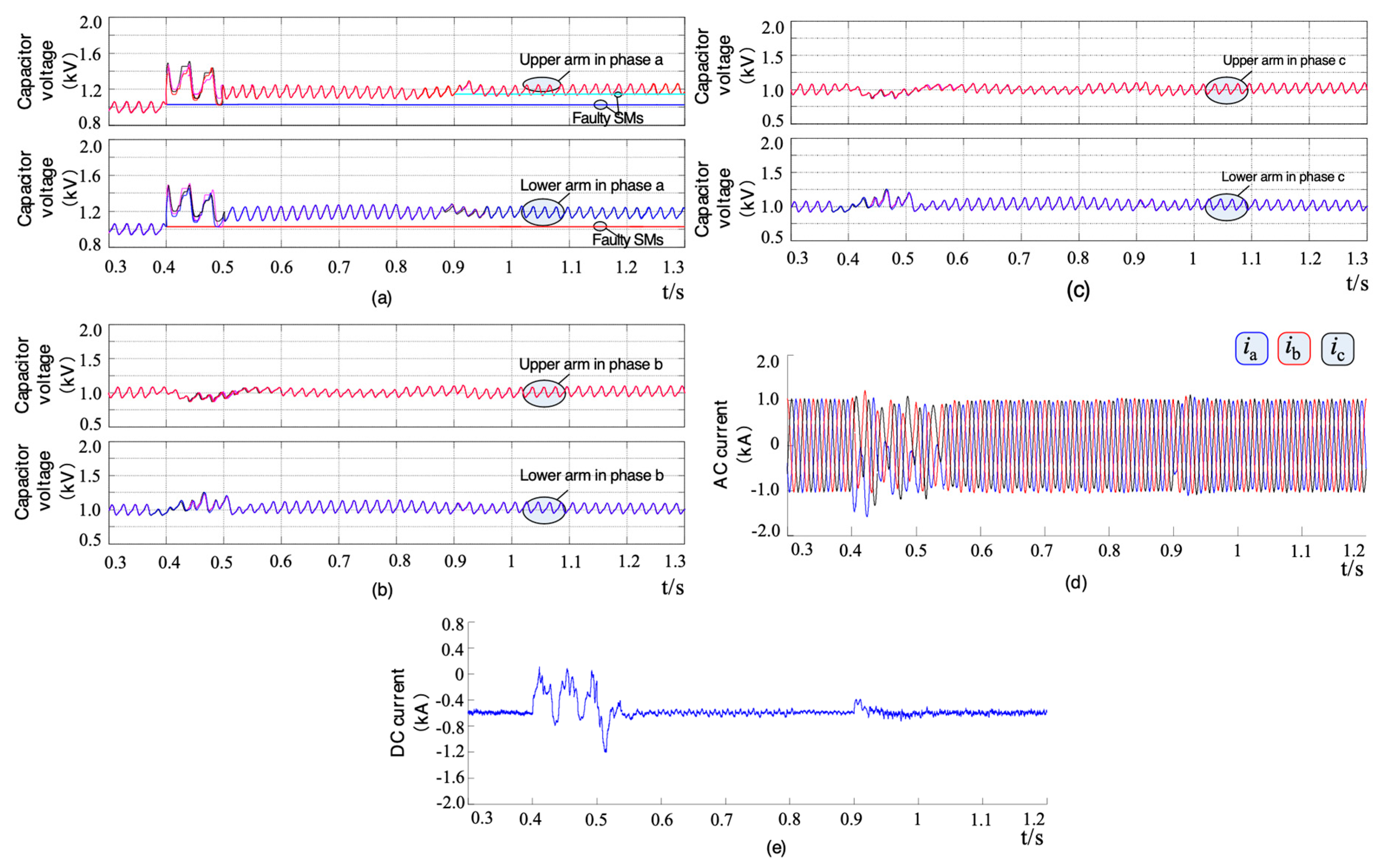
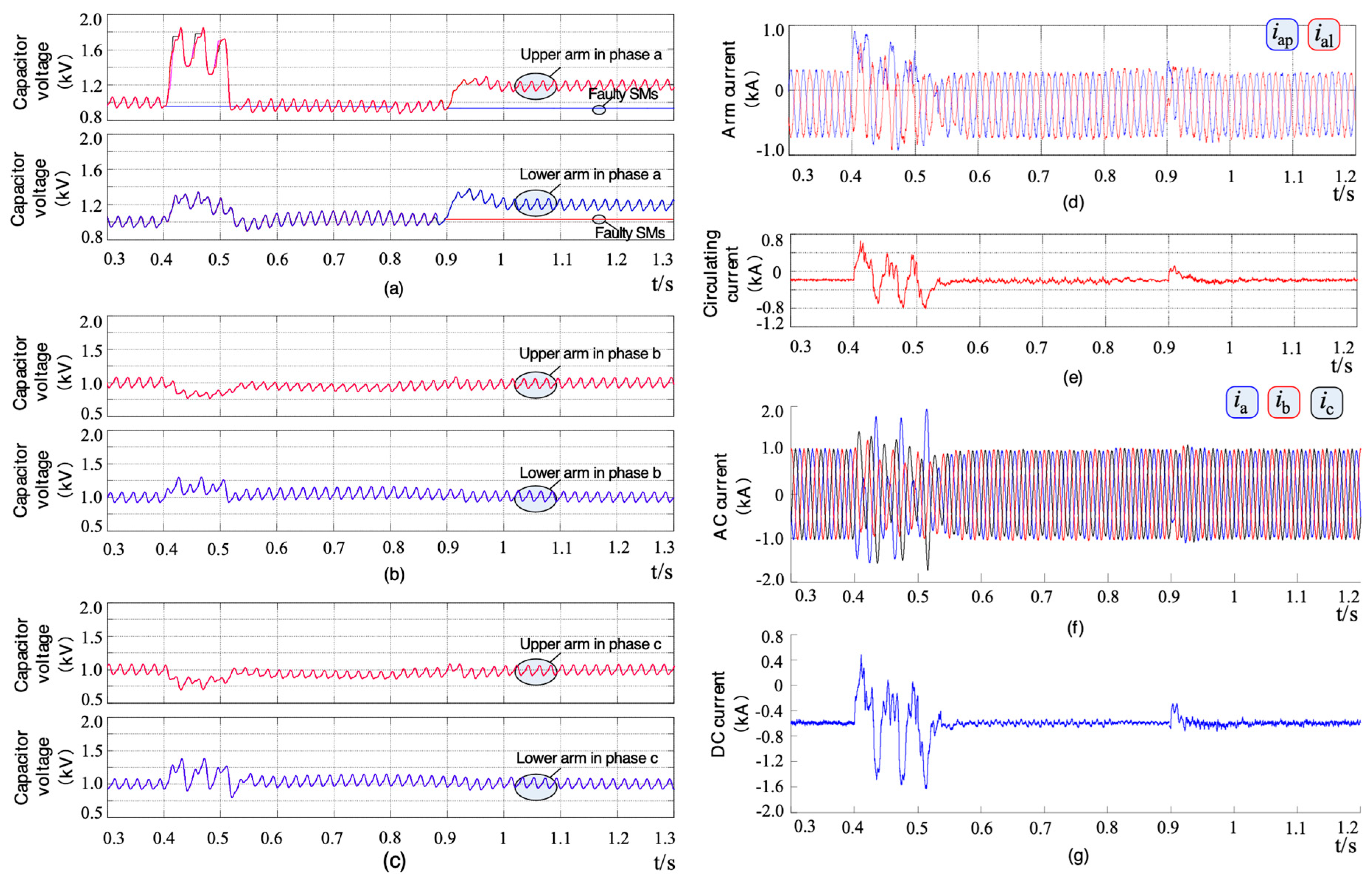
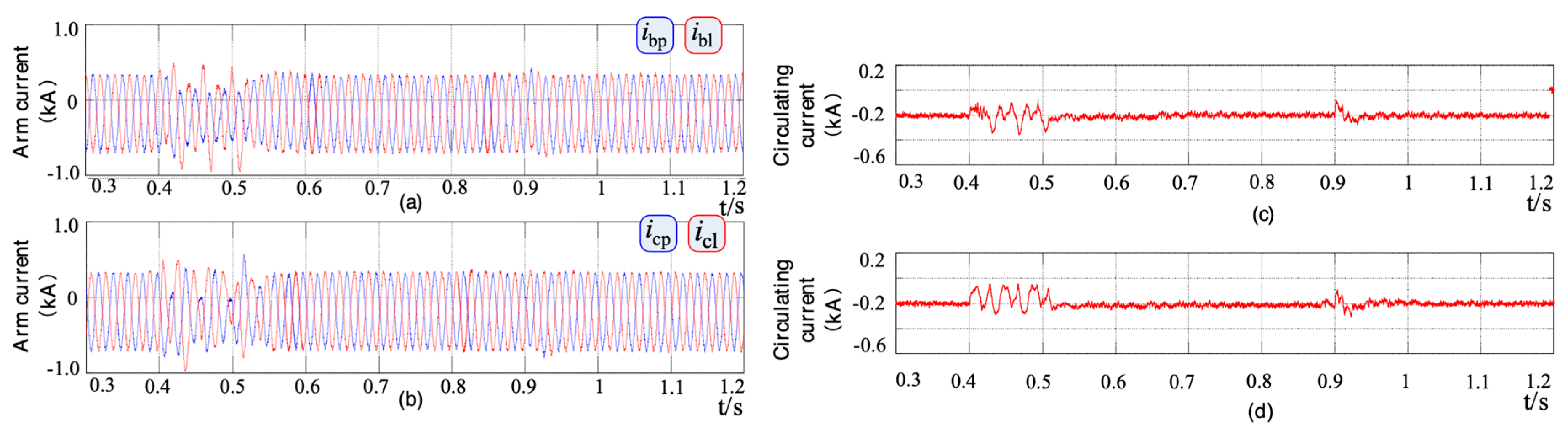
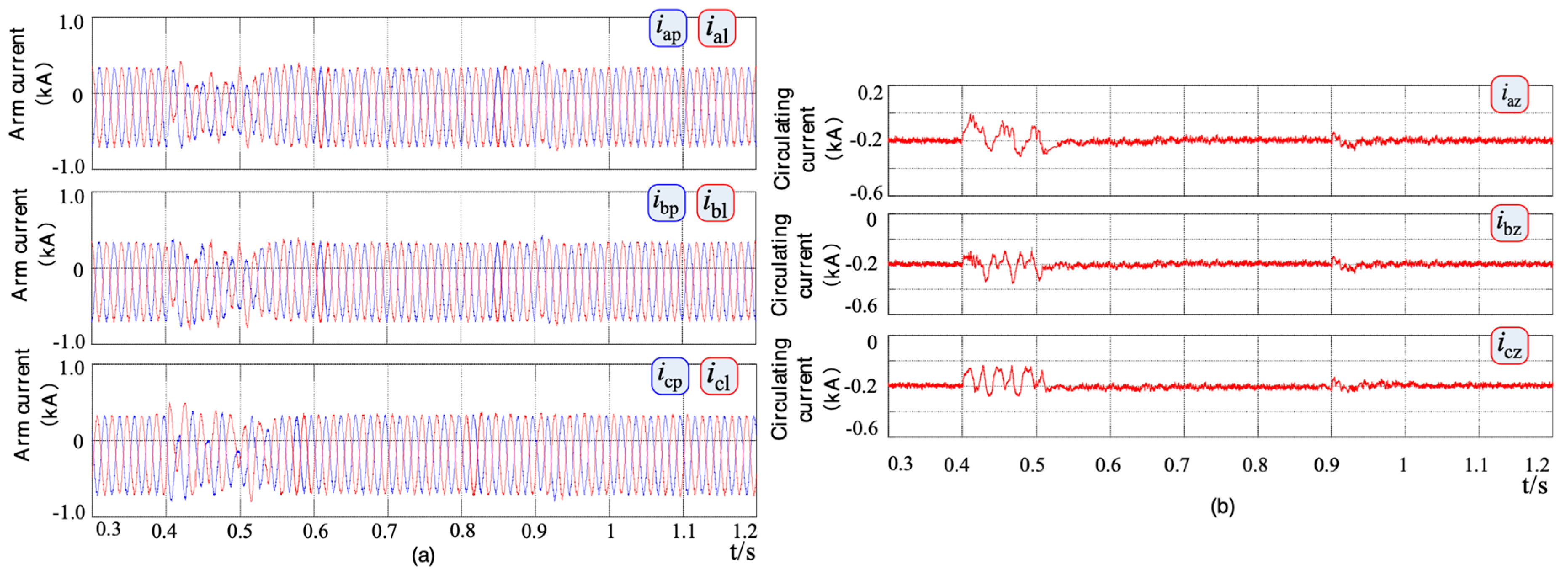
5. Simulation Studies

A three-phase MMC simulation model is built in MATLAB/Simulink simulation software as shown in Figure 1. The main parameters of the simulation system are shown in Table 1. In the simulation process, the circulating current suppression strategy is always put into operation when the grid is connected [29].

5.1. Case 1

Fault condition 1: Single arm fault to symmetrical arm fault. When the system operates to t = 0.4 s, five SMs in the upper arm of phase a occur fault; at t = 0.5 s, the fault-tolerant control strategy is enabled; at t = 0.9 s, five SMs in the lower arm of phase a are failed again. Figure 9 is the related simulation results.
From Figure 9a–g, it can be seen that: (1) When the system is in normal operation, the voltage and current of the system are stable. (2) When the SMs fail at t = 0.4 s, the SM capacitor voltage of each phase begins to oscillate irregularly, the arm current and AC grid-connected current show an asymmetric state, and the DC current and circulating current of the system also appear relatively fluctuant. (3) When fault-tolerant control strategy is enabled at t = 0.5 s, the system SM voltage immediately starts to return to normal value, the fluctuation of circulating current and DC current is obviously suppressed, and the arm current and AC grid-connected current are quickly restored to symmetry and stable operation. (4) When the SMs occur fault again at t = 0.9 s, through the control of the increasing carrier wave amplitude, the SM voltage of fault phase is in the boost operation (up to about 1.3 kV) and the SM voltage of the non-fault phase continues to maintain the stable operation of the original rated value (1.0 kV), and all the current can continue to maintain stable operation through rapid transient regulation.
The above results show that the proposed fault-tolerant control strategy can quickly realize fault-tolerant operation after the SM fault, and can respond quickly when the single arm SM fault transforms to symmetrical fault.

5.2. Case 2

Fault condition 2: Single arm fault to arm asymmetric fault. When the system operates to t = 0.4 s, five SMs in the upper arm of phase a occur fault; at t = 0.5 s, the fault-tolerant control strategy is enabled; at t = 0.9 s, three SMs in the lower arm of phase a are failed again. Figure 10 and Figure A1 are the related simulation results.
It can be seen that: (1) Since the operation conditions of the system before t = 0.9 s are the same as the fault condition 1, the simulation of the system in 0~0.9 s is basically the same as the fault condition 1. (2) When the SMs occur fault again at t = 0.9 s, the system is operating asymmetrically in the upper and lower arms. The SM voltage of the fault phase is increased to about 1.2 kV by increasing carrier wave amplitude, while the SM voltage of the non-fault phase keeps the stable operation with the original rated value, and all the current can continue to maintain stable operation through rapid transient regulation.
Because the χa (the smaller number of faulty SMs of phase a) is smaller than the fault condition 1, the boosting amplitude of SM voltage of the fault phase is smaller than the fault condition 1, and the impact of the AC and DC current of the system is relatively small at t = 0.9 s. The above results also show that the proposed fault-tolerant control strategy can effectively achieve fault-tolerant operation after the SM fault, and can also respond quickly when the single arm fault transforms to the asymmetric arm fault.

5.3. Case 3

Fault condition 3: Arm symmetrical fault to arm asymmetric fault. When the system operates to t = 0.4 s, three SMs in the upper arm and lower arm of phase occur fault simultaneously; at t = 0.5 s, the fault-tolerant control strategy is enabled; at t = 0.9 s, two SMs in the upper arm of phase a are failed again. Figure 11 and Figure A2 are the related simulation results.
It can be seen that: (1) When the system is in normal operation, the voltage and current of the system are stable. (2) When the SMs fail at t = 0.4 s, the capacitor voltage of each phase SM begins to oscillate irregularly, the arm current and AC grid-connected current show an asymmetric state. But at this time, the arm structure is still in symmetrical state and the number of faulty SMs is smaller than fault conditions 1 and 2, so the oscillation amplitude of voltage and current is slight compared with the fault conditions 1 and 2. (3) When fault-tolerant control strategy is enabled at t = 0.5 s, the SM voltage of the fault phase is increased to about 1.2 kV, while the SM voltage of the non-fault phase keeps the stable operation with the original rated value, and all the current can continue to maintain stable operation rapidly. (4) When the SMs occur fault again at t = 0.9 s, through the control of the limiting modulation wave amplitude, the system can continue to operate stably.
Based on the simulation results of fault conditions 1–3, it can be seen that the fault-tolerant control strategy of the SM proposed in this paper can effectively realize the fault-tolerant operation control of the system after the SM fault, and can respond flexibly to different fault conditions of the arm, and can respond quickly when the fault state of the arm changes.

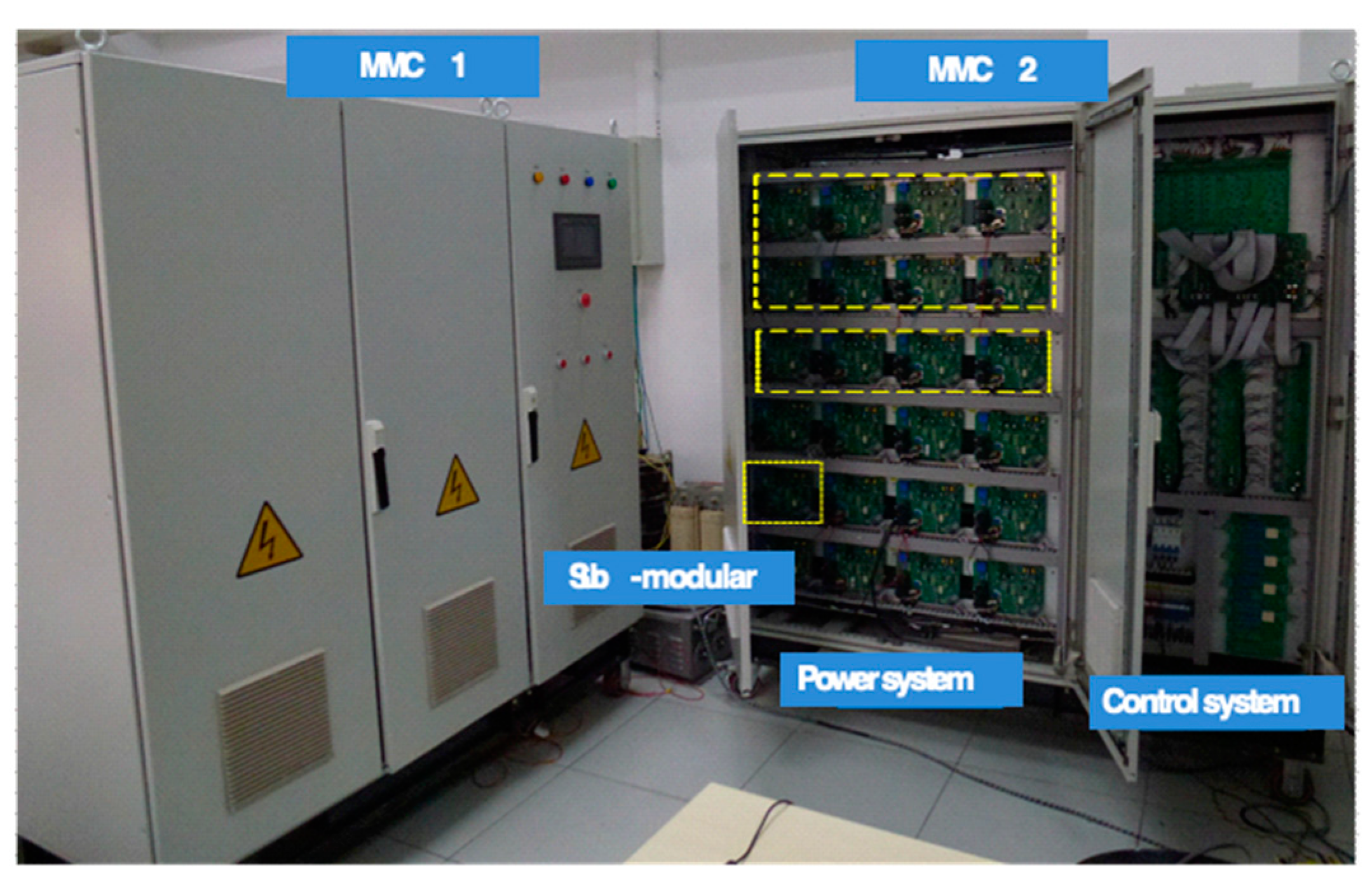
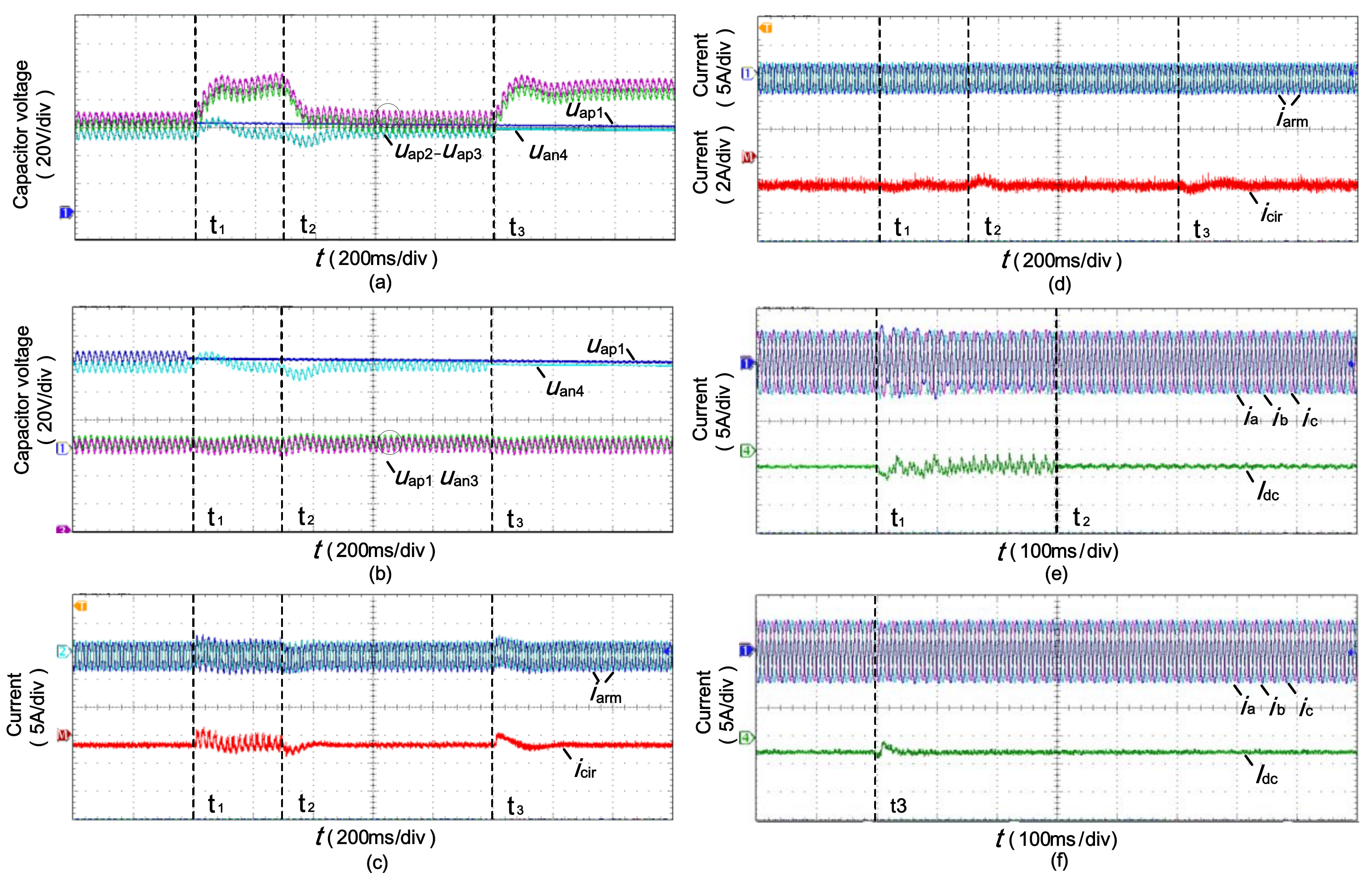
6. Experimental Studies

In order to verify the fault-tolerant control strategy, a 2-terminal MMC-based experimental platform is built in the laboratory. The experimental platform is shown in Figure 12. Among them, MMC1 is the DC voltage source and MMC2 is to verify the control strategy. The basic parameters of MMC prototype are shown in Table 2.
In the course of the experiment, the SM1 in the upper arm of phase a occurs fault at t1, fault-tolerant control strategy is enabled at t2 and the SM4 in the lower arm of phase a occurs fault again at t3. Figure 13 shows the relevant experimental waveform.
It can be seen from Figure 13 that: (1) Before the fault, the system operates steadily. When the SM1 fails at t1, the capacitor voltage of SM1 begins to oscillate irregularly, the arm current and AC grid-connected current show an asymmetric state, and the DC current and circulating current of the system also appear relatively fluctuant. (2) When the fault-tolerant control strategy is put into operation at t2, SM1 voltage starts to return to normal value and the arm current and AC grid-connected current are restored to symmetry and stable operation. (3) When the SM4 occurs fault again at t3, the SM4 voltage of the fault phase is increased to 80 V, while the SM voltage of the non-fault phase keeps the stable operation with the original rated value (60 V). There is no major impact on the system in the process, and the system current is still in a stable state.
Limited by the number of SMs of the experimental platform, the experiment only validates the fault condition 1, but the experimental results are basically consistent with the simulation. The results of simulation and experiment show that the design of fault-tolerant control strategy proposed in this paper is reasonable and effective, and it is helpful to realize fault-crossing of SMs under different operating conditions.

7. Conclusions

The fault-tolerant operation issue of MMC under SM faults is studied in this paper. The main works and contributions can be summarized as:
(1)
The traditional zero-sequence voltage injection fault-tolerant control algorithm is analyzed detailed. It reveals that the traditional method is easy to implement under the signal arm faulty state. However, if the SM simultaneously occurring faults in the upper and lower arms or appearing multiple arm failures, the required zero-sequence voltages will be calculated difficult. The SM fault-crossing is complicated to realize.
(2)
A novel fault-tolerant control strategy based on PD-PWM is proposed, which has three main benefits: (i) it has carrier and modulation wave dual correction mechanism, which control ability is more higher and flexible; (ii) it only needs to inject zero-sequence voltage in half a cycle of the modulation wave, which simplifies the complexity of traditional zero-sequence voltage injection control algorithms and much easier for implement; (iii) furthermore, the zero-sequence voltage can even be avoided injecting under the symmetrical fault conditions.
(3)
The simulations in the MATLAB/SIMULINK and experiments with 2-terminal a MMC-based prototype are all studied with the proposed control strategy under different fault conditions. The results confirm the efficiency of the control strategy.

Author Contributions

Conceptualization, W.W., T.W. and Q.H.; Formal analysis, J.Y.; Writing—original draft, J.Y.; Writing—review & editing, J.Y.

Acknowledgments

This research work was supported by National Key R&D Program of China (2016YFB0900900), National Natural Science Foundation of China (51607171), Chinese Academy of Sciences Youth Innovation Association (2017180).

Conflicts of Interest

The authors declare no conflict of interest.

Appendix A

Figure A1. Simulation results of fault condition 2: (a) Arm current of phase b; (b) Arm current of phase c; (c) Circulating current of phase b; (d) Circulating current of phase c.
Energies 12 00020 g0a1
Figure A2. Simulation results of fault condition 3: (a) Arm current of phase j (j = a,b,c); (b) Circulating current of phase j (j = a,b,c).
Energies 12 00020 g0a2

References

  1. Popova, L.; Pyrhonen, J.; Ma, K.; Blaabjerg, F. Device loading of modular multilevel converter MMC in wind power application. In Proceedings of the 2014 International Power Electronics Conference (IPEC-Hiroshima 2014—ECCE-ASIA), Hiroshima, Japan, 18–21 May 2014; pp. 548–554. [Google Scholar]
  2. Gowaid, I.A.; Adam, G.P.; Ahmed, S.; Holliday, D.; Williams, B.W. Analysis and design of a modular multilevel converter with trapezoidal modulation for medium and high voltage DC-DC transformers. IEEE Trans. Power Electron. 2015, 30, 5439–5457. [Google Scholar] [CrossRef]
  3. Perez, M.A.; Bernet, S.; Rodriguez, J.; Kouro, S.; Lizana, R. Circuit topologies, modeling, control schemes, and applications of modular multilevel converters. IEEE Trans. Power Electron. 2018, 30, 4–17. [Google Scholar] [CrossRef]
  4. Nami, A.; Liang, J.; Dijkhuizen, F.; Demetriades, G. Modular multilevel converters for HVDC applications: Review on converter cells and functionalities. IEEE Trans. Power Electron. 2015, 30, 18–36. [Google Scholar] [CrossRef]
  5. Lesnicar, A.; Marquardt, R. An innovative modular multilevel converter topology suitable for a wide power range. In Proceedings of the IEEE Bologna Power Tech Conference Proceedings, Bologna, Italy, 23–26 June 2003; pp. 23–26. [Google Scholar]
  6. Debnath, S.; Saeedifard, M. Simulation-based gradient-descent optimization of modular multilevel converter controller parameters. IEEE Trans Ind. Electron. 2016, 63, 102–112. [Google Scholar] [CrossRef]
  7. Li, Y.; Jiang, W.; Yu, S.; Zou, X. Design of zhoushan multi-terminal VSC-HVDC transmission project. High Voltage Eng. 2014, 40, 2490–2496. [Google Scholar]
  8. Wu, W.; Wu, X.; Yin, J.; Jing, L.; Wang, S.; Li, J. Characteristic analysis and fault-tolerant control of circulating current for modular multilevel converters under SM faults. Energies 2017, 10, 1827. [Google Scholar] [CrossRef]
  9. Abdelsalam, M.; Tennakoon, S.; Griffiths, A.L.; Marei, M. Investigation of sub-module fault types of modular multi-level converters in HVDC networks. In Proceedings of the International Universities Power Engineering Conference (UPEC), Stoke, UK, 1–4 September 2015; pp. 1–6. [Google Scholar]
  10. Jiang, W.; Wang, C.; Wang, M. Fault detection and remedy of multilevel inverter based on BP neural network. In Proceedings of the Asia-Pacific Power and Energy Engineering Conference (APPEEC), Shanghai, China, 27–29 March 2012; pp. 1–4. [Google Scholar]
  11. Moon, J.W.; Kim, C.S.; Park, J.W. Circulating current control in MMC under the unbalanced voltage. IEEE Trans. Power Deliv. 2013, 28, 1952–1959. [Google Scholar] [CrossRef]
  12. Son, G.; Lee, H.J.; Nam, T. Design and control of a modular multilevel HVDC converter with redundant power modules for noninterruptible energy transfer. IEEE Trans. Power Deliv. 2012, 27, 1611–1619. [Google Scholar]
  13. Konstantinou, G.; Pou, J.; Ceballos, S. Active redundant sub-module configuration in modular multilevel converters. IEEE Trans. Power Deliv. 2013, 28, 2333–2341. [Google Scholar] [CrossRef]
  14. Liu, G.; Xu, Z.; Xue, Y. Optimized control strategy based on dynamic redundancy for the modular multilevel converter. IEEE Trans. Power Electron. 2015, 30, 339–348. [Google Scholar] [CrossRef]
  15. Li, S.; Wang, Z.; Wang, G. Fluctuation volt age control and fault-tolerant operation of modular multilevel converters with zero-sequence injection. Int. Trans. Electr. Energy Syst. 2014, 24, 944–959. [Google Scholar] [CrossRef]
  16. Hu, P.; Jiang, D.; Zhou, Y. Energy-balancing control strategy for modular multilevel converters under submodule Fault Conditions. IEEE Trans. Power Electron. 2014, 29, 5021–5029. [Google Scholar] [CrossRef]
  17. Peter, W. Enhancing the reliability of modular medium-voltage drives. IEEE Trans Ind. Electron. 2002, 49, 948–954. [Google Scholar]
  18. Jose, R.; Peter, W.; Jorge, P.; Rodrigo, M.; Maria, J. Operation of a medium-voltage drive under faulty conditions. IEEE Trans Ind. Electron. 2005, 52, 1080–1085. [Google Scholar]
  19. Pablo, L.; Gabriel, O. Extended operation of cascade multicell converters under fault condition. IEEE Trans Ind. Electron. 2009, 56, 2697–2703. [Google Scholar]
  20. Fernanda, C.; Humberto, P.; Cassiano, R. Generalized carrier-based modulation strategy for cascaded multilevel converters operating under fault conditions. IEEE Trans. Ind. Electron. 2012, 59, 679–689. [Google Scholar]
  21. Yang, Q.; Qin, J. A post-fault strategy to control the modular multilevel converter under submodule failure. IEEE Trans. Power Deliv. 2012, 27, 1538–1547. [Google Scholar]
  22. Shen, K.; Xiao, B.; Mei, J. A modulation reconfiguration based fault-tolerant control scheme for modular multilevel converters. In Proceedings of the IEEE Applied Power Electronics Conference and Exposition (APEC), Long Beach, CA, USA, 17–31 March 2013; pp. 3251–3255. [Google Scholar]
  23. Yang, W.; Song, Q.; Xu, S.; Rao, H.; Liu, W. An MMC topology Based on unidirectional current H-bridge submodule with active circulating current injection. IEEE Trans. Power Electron. 2018, 33, 3870–3883. [Google Scholar] [CrossRef]
  24. Ning, L.; Venkata, D. Dynamic electro-magnetic-thermal modeling of MMC-based DC–DC converter for real-time simulation of MTDC grid. IEEE Trans. Power Deliv. 2018, 33, 1337–1347. [Google Scholar]
  25. Xu, J.; Penghao, Z.; Zhao, C. Reliability analysis and redundancy configuration of MMC with hybrid submodule topologies. IEEE Trans. Power Electron. 2016, 31, 2720–2729. [Google Scholar] [CrossRef]
  26. Lu, C. Research on the Control Strategy of Modular Multilevel Converter; China University of Ming and Technology: Beijing, China, 2014. [Google Scholar]
  27. Wang, D.; Yang, J.; Chen, Z.; Mao, C.; Lu, J. A Transformerless medium voltage multiphase motor drive system. Energies 2016, 9, 323. [Google Scholar] [CrossRef]
  28. Meshram, P.M.; Borghate, V.B. A Novel Voltage Balancing Method of Modular Multilevel Converter (MMC). In Proceedings of the International Conference on Energy, Automation and Signal, Bhubaneswar, Odisha, India, 28–30 December 2011; pp. 1–5. [Google Scholar]
  29. Li, J.; Jin, X.; Wu, X. Analysis of Fault Circulating current without redundant SM and its suppression strategy. Power Syst. Technol. 2016, 40, 32–39. [Google Scholar]
Figure 1. Topology structure of three-phase modular multilevel converter (MMC).
Energies 12 00020 g001
Figure 2. Schematic diagram basic control: (a) Diagram of the pulse-width modulation (PD-PWM); (b) Diagram of the capacitor voltage sorting algorithm.
Energies 12 00020 g002
Figure 3. Diagram of zero sequence voltage injection modulation: (a) Schematic diagram of fault modulation wave of upper arm; (b) Schematic diagram of fault modulation wave of upper arm and lower arm.
Energies 12 00020 g003
Figure 4. Overall flow chart of the proposed fault-tolerant control strategy.
Energies 12 00020 g004
Figure 5. Modulation diagram of one phase under the normal operation.
Energies 12 00020 g005
Figure 6. Modulation diagram of the faulty phase under carrier wave correction.
Energies 12 00020 g006
Figure 7. Final modulation diagram of the faulty phase under fault-tolerant control.
Energies 12 00020 g007
Figure 8. Schematic diagram of control system.
Energies 12 00020 g008
Figure 9. Simulation results of fault condition 1: (a) Capacitor voltage of phase a; (b) Capacitor voltage of phase b; (c) Capacitor voltage of phase c; (d) Arm current of phase j (j = a,b,c); (e) Circulating current of phase j (j = a,b,c); (f) AC current; (g) DC-link current.
Energies 12 00020 g009aEnergies 12 00020 g009b
Figure 10. Simulation results of fault condition 2: (a) Capacitor voltage of phase a; (b) Capacitor voltage of phase b; (c) Capacitor voltage of phase c; (d) Arm current of phase a; (e) Circulating current of phase a; (f) AC current; (g) DC-link current.
Energies 12 00020 g010
Figure 11. Simulation results of fault condition 3: (a) Capacitor voltage of phase a; (b) Capacitor voltage of phase b; (c) Capacitor voltage of phase c; (d) AC current; (e) DC-link current.
Energies 12 00020 g011
Figure 12. The photograph of MMC experiment prototype.
Energies 12 00020 g012
Figure 13. Waveforms of experiment: (a) Capacitor voltage of phase a; (b) Capacitor voltage of phase b; (c) Circulating current of phase a; (d) Circulating current of phase b; (e) AC current and DC current from t1 to t3; (f) AC current and DC current after t3.
Energies 12 00020 g013
Table 1. Main parameters of the simulation system.
ParametersValue
Ac system nominal voltage10 kV
Ac System inductance Ls5 mH
Fundamental frequency50 Hz
Ac system power losses Rs0.03 Ω
Arm inductance Lm5 mH
Series arm resistance Rm0.01 Ω
Dc bus voltage Udc20 kV
Number of SMs per arm N20
Number of redundant SMs per arm5
Sub-module capacitor C2000 μF
Transformer ratio1:1 (Y/Δ)
Table 2. Experimental parameters of the MMC prototype.
ParametersValue
AC System inductance Ls5 mH
Arm inductance Lm5 mH
DC bus voltage Udc20 kV
Number of SMs per arm N4
Number of redundant SMs per arm1
Sub-module capacitor C2000 μF
Transformer ratio380 V/380 V (Y/Δ)

