Article

A Highly Efficient Single-Phase Three-Level Neutral Point Clamped (NPC) Converter Based on Predictive Control with Reduced Number of Commutations

School of Electrical and Electronics Engineering, Chung-ang University, Seoul 06974, Korea
*
Author to whom correspondence should be addressed.
Energies 2018, 11(12), 3524; https://doi.org/10.3390/en11123524
Submission received: 16 November 2018 / Revised: 14 December 2018 / Accepted: 14 December 2018 / Published: 18 December 2018

Abstract

:
This paper proposes a highly efficient single-phase three-level neutral point clamped (NPC) converter operated by a model predictive control (MPC) method with reduced commutations of switches. The proposed method only allows switching states with none or a single commutation at the next step as candidates for future switching states for the MPC method. Because the proposed method preselects switching states with reduced commutations when selecting an optimal state at a future step, the proposed method can reduce the number of switchings and the corresponding switching losses. Although the proposed method slightly increases the peak-to-peak variations of the two dc capacitor voltages, the developed method does not deteriorate the input current quality and input power factor despite the reduced number of switching numbers and losses. Thus, the proposed method can reduce the number of switching losses and lead to high efficiency, in comparison with the conventional MPC method.

1. Introduction

Recently, multilevel converters have become popular in a variety of high-power systems owing to their low voltage stress, improved waveform qualities, and low electromagnetic interference (EMI) compared to two-level converters [1,2]. Among several kinds of multilevel converters, three-level neutral point clamped (NPC) converters with relatively simple configurations have been realized for many application areas. In addition to three-phase NPC converters, single-phase three-level NPC converters have been employed for high-speed traction systems as well. In order to control single-phase three-level NPC converters, traditional carrier-based pulse width modulation (CBPWM) methods combined with linear proportional and integral (PI) controllers have been investigated to synthesize ac sinusoidal current waveforms with three-level NPC converters. Aside from their adjustable ac voltage and current synthesis, the NPC converters require balancing of the two dc capacitor voltages because of their structure, which has two split dc capacitors in the dc link. As a result, CBPWM methods with offset voltage injection to remove imbalance of neutral point (NP) voltage in the NPC converters have been often used [3,4,5,6,7].
Recently, model predictive control (MPC) methods have been studied for numerous power converters including three-level NPC converters [8,9,10]. There have been several studies on MPC algorithms for single-phase NPC converters as well as three-phase NPC converters [11,12,13]. In the MPC methods for single-phase NPC converters, a cost function to determine an optimal switching state generally consists of two terms combined with a weighting factor not only to control both the ac sinusoidal currents but also to balance the two capacitor voltages. The ac sinusoidal current is controlled by changing the converter voltage levels, whereas the NP voltage balance is adjusted by using redundant switching states that yield the same voltage level.
The conventional MPC method selects an optimal switching state among nine switching states allowed by the single-phase three-level NPC converter on the basis of a cost function considering the ac source current and the NP voltage balance. Consideration of all possible switching states in the conventional method can choose a switching state involved in many commutations as an optimal switching state for the next step, which can lead to an increased number of switchings and corresponding switching losses [14,15,16,17,18]. In addition, the conventional MPC method changes the optimal switching state by evaluating the capacitor voltage balance term using the redundant switching states to equal the two capacitor voltages [19,20] owing to a slight voltage difference even when the converter does not require a change in the voltage level. Thus, this operation can increase the number of switchings and switching losses as well [21,22]. Several trials to reduce switching losses based on the model predictive control methods have been addressed for a variety of power converters in literatures. In [23,24], approaches to reduce switching losses of matrix converters have been addressed. Ref. [23] proposed a switching loss reduction technique by adding an additional term related with a number of future commutations to a cost function used to control the matrix converter. In [24], a trial to decrease switching losses of the matrix converter has been presented, where a cost function includes an extra term directly representing switching losses at next step by calculating switch currents and switch voltages. In [25], a model predictive control method for modular multilevel converters (MMCs) has been developed with a cost function which is aimed at the elimination of the MMC circulating currents, regulating the arm voltages, and controlling the ac-side currents. In addition, this strategy tried to reduce power losses by decreasing the submodule switching frequency. In [26,27], reduction techniques of switching losses for two-level voltage source inverters have been presented. Ref. [26] proposed a switching strategy based on the model predictive control method to clamp one phase with the largest load current among the three legs in the voltage source inverter every sampling period, which can successfully reduce switching losses of the voltage source inverter. In addition, a model predictive control method for the voltage source inverter has been developed to reduce switching losses by injecting future zero-sequence voltage [27]. This approach decreased the switching losses by implementing optimal discontinuous pulse patterns to stop switching operations at vicinity of peak values of load currents. However, there has not been, to the authors’ best knowledge, tried to reduce switching losses, using a trade-off between switching losses and capacitor voltage balancing in the three-level NPC converters, although several trials to reduce switching losses based on the model predictive control methods have been addressed for a variety of power converters.
In this paper, a highly efficient algorithm with a reduced number of switching and low switching losses for single-phase three-level neutral point clamped (NPC) converters is proposed based on a model predictive control (MPC) method with a decreased number of commutations of switches. The proposed method pre-excludes, from the candidates for possible future switching states, the switching states that yield more than two commutations in the next sampling period. As a result, the proposed technique can reduce the number of switchings and switching losses by utilizing switching states involving no commutation or only one commutation during every sampling instant for single-phase three-level NPC converters. In addition, the developed method does not deteriorate the input current quality or input power factor despite the reduced switching numbers and losses. Although the proposed method slightly increases the peak-to-peak variations of the two dc capacitor voltages at the expense of reduced commutation, the increased voltage variation is not high. Thus, the proposed method can obtain high efficiency and low switching losses at the expense of a slightly increased peak-to-peak variation of the NP voltage. The performance of the proposed method with a reduced number of switchings and higher efficiency is evaluated in terms of the total harmonic distortion (THD) and peak-to-peak variations of the capacitor voltages. Simulations and experimental results are presented to verify the effectiveness of the proposed method.

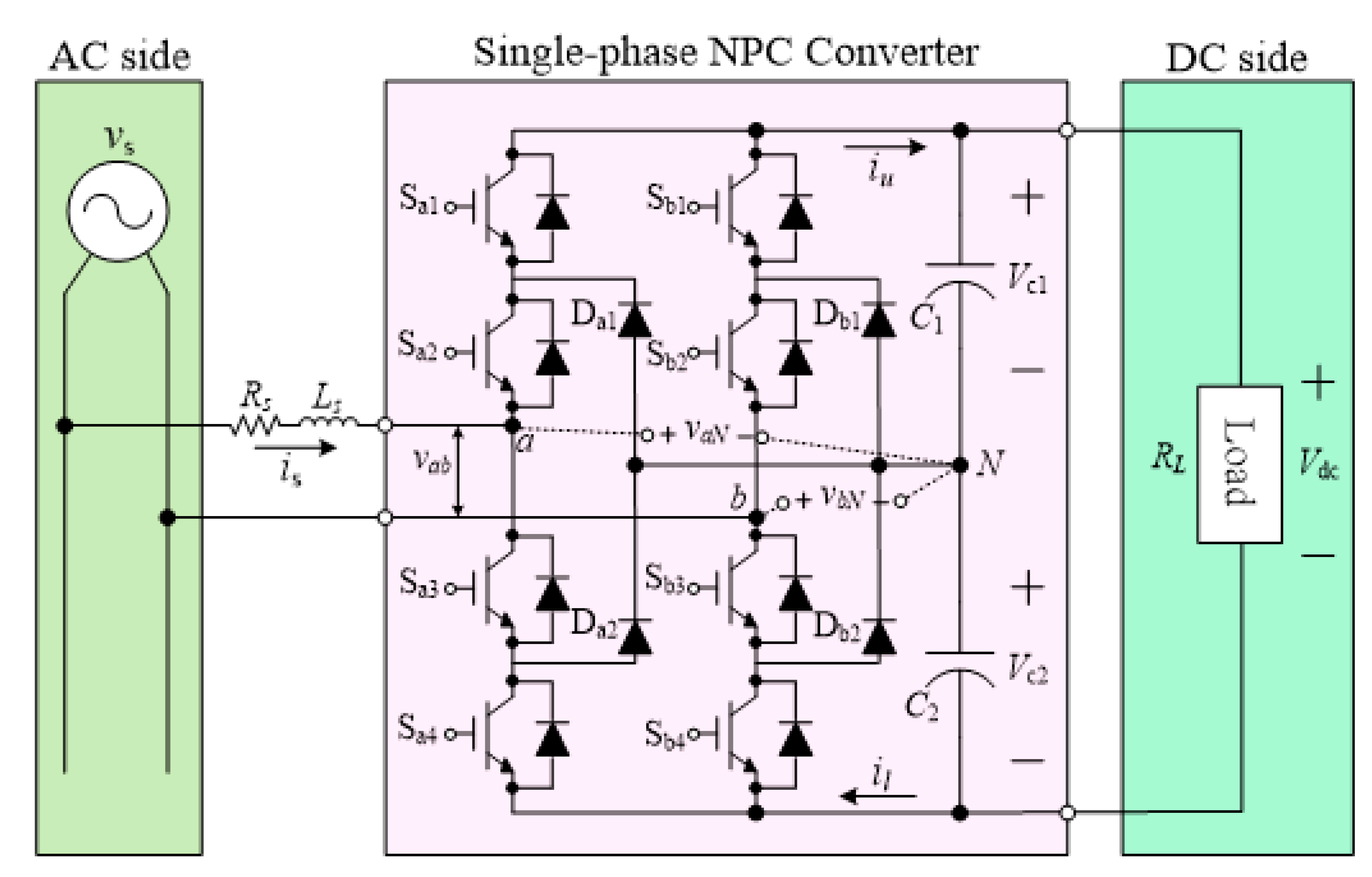
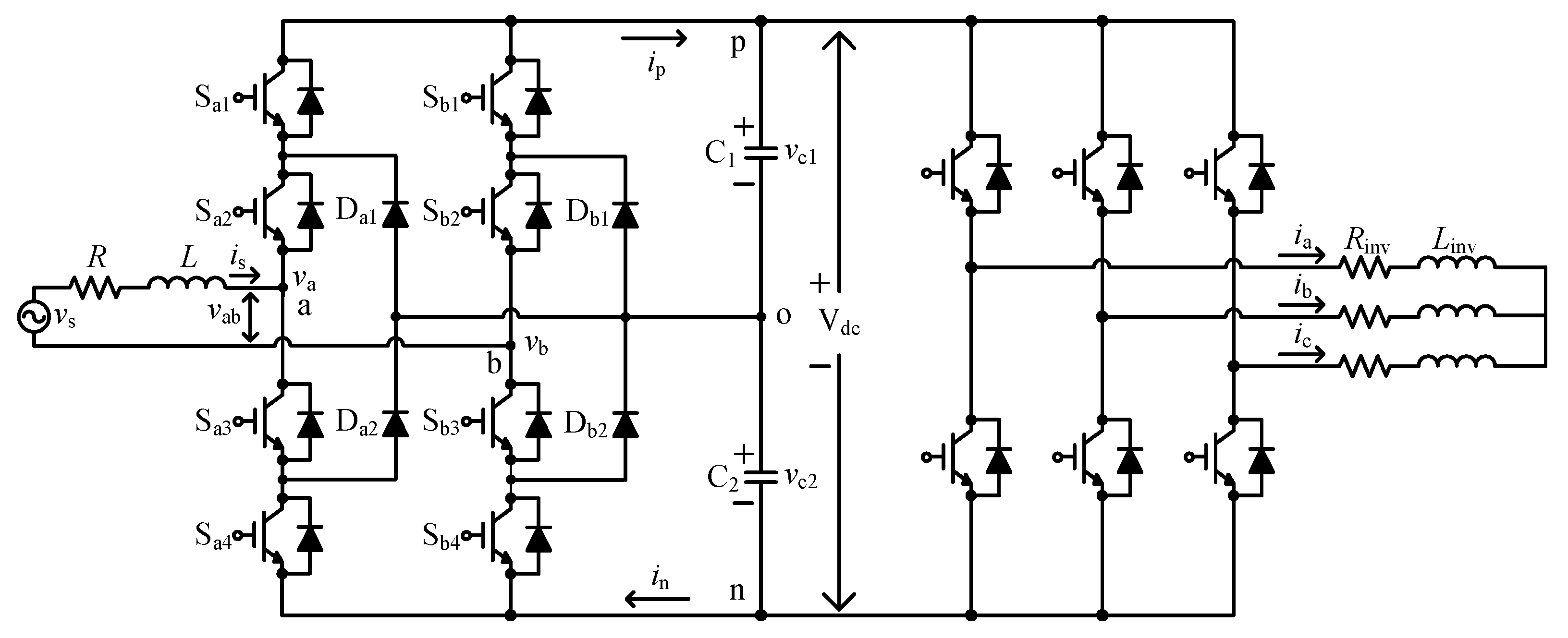
2. Single-Phase Three-Level NPC Converter and Model Predictive Control Method

Figure 1 shows a circuit diagram for the single-phase three-level NPC converter. As shown in Figure 1, the single-phase three-level NPC converter has an input inductor Ls and resistor Rs as an ac side filter, as well as two capacitors C1 and C2 at the dc side. In addition, vc1 and vc2 are the dc voltage of each capacitor, and RL is a load resistor. Switches Saj and Sbj(j = 1, 2, 3, 4) are Insulated Gate Bipolar Transistors (IGBTs) at the a-phase and b-phase, respectively. The switch states at each phase, produced by the converter, can be defined as a function of the switching status of the two upper devices as:
S x = { 1 0 1 ( S x 1 , S x 2 : O N ) ( S x 2 , S x 3 : O N ) ( S x 3 , S x 4 : O N ) ( x   =   a   or   b )
The two switches Sx1 and Sx3 operate complementarily. Similarly, Sx2 and Sx4 work in a complementary manner. As a result, the switching status of the two lower devices is automatically determined by the upper switches. Owing to possible combinations of the switching states of (1) in the a and b phases, a total of nine operating states can be generated by the single-phase three-level NPC converter. On the basis of nine operating states, the phase switching state, upper device switching status, and converter input voltage vab are listed in Table 1. The nine operating states yield five voltage levels for the converter input voltage vab, which provides the single-phase NPC converter with redundancy.
As shown in Table 1, the two states (1, 0) and (0, −1) for (Sa, Sb) are redundant switching states that apply the same voltage level to the converter input terminal of the single-phase three-level NPC converter by assuming that the two capacitor voltages are well balanced. Likewise, the states (0, 1) and (−1, 0) for (Sa, Sb) are also redundant because they yield the equal converter input voltage vab. These redundancies can be utilized to balance the two capacitor voltages vc1 and vc2. The currents iu and il shown in Figure 1 can be expressed using the switching status and the source current is as in (2) and (3). Thus, they can be obtained without additional measurements [16]:
i u = S a ( S a + 1 ) S b ( S b + 1 ) 2 i s
i l = S a ( S a 1 ) S b ( S b 1 ) 2 i s
The capacitor voltage dynamics of the dc link are calculated by using differential equations:
d v c 1 d t = 1 C 1 i u
d v c 2 d t = 1 C 2 i l
Using a constant sampling period Ts, the capacitor voltage dynamics in the discrete-time domain are described as:
d v c m d t v c m ( k + 1 ) v c m ( k ) T s ( m = 1 ,   2 )
Using (6), Equations (4) and (5) can be expressed in the discrete time domain as:
v c 1 ( k + 1 ) = v c 1 ( k ) + T s C 1 ( S a ( S a + 1 ) S b ( S b + 1 ) 2 ) i s
v c 2 ( k + 1 ) = v c 2 ( k ) T s C 2 ( S a ( S a 1 ) S b ( S b 1 ) 2 ) i s
The input current of the ac side shown in Figure 1 is expressed in the continuous time domain as:
v s = R i s + L d i s d t + v a b
Equation (9) is expressed in the discrete time domain as:
i s ( k + 1 ) = ( 1 R T s L ) i s ( k ) + T s L ( v s ( k ) v a b ( k ) )
The ac source current at the next step, is(k + 1), in (10) can have five possible movements owing to the five possible voltage levels for vab(k). The single-phase three-level NPC converter needs to balance the two capacitor voltages by manipulating the phase switching states Sa(k) and Sb(k) shown in (7) and (8) as well as control the source current by changing the converter input voltage vab(k) in (10). As a result, the cost function with two terms for the ac source current control part and the neutral point (NP) voltage control part of the two capacitor voltages is:
g = | i s * ( k + 1 ) i s ( k + 1 ) | + λ c | v c 1 ( k + 1 ) v c 2 ( k + 1 ) |
where λc represents the weighting factor of the capacitor voltage balancing term in the cost function. Moreover, the future ac reference current can be expressed with past and present currents from a Lagrange extrapolation as [28,29,30,31]:
i s * ( k + 1 ) = 3 i s * ( k ) 3 i s * ( k 1 ) + i s * ( k 2 )
where i s * ( k ) is the present current, and i s * ( k 1 ) and i s * ( k 2 ) are the reference value of the one-step and two-step past ac source currents, respectively. The ac sinusoidal current is controlled by changing the converter voltage levels, whereas the NP voltage balance is adjusted by using redundant switching states that yield the same voltage level. As a result, the conventional MPC method changes the optimal switching state by evaluating the capacitor voltage balance term using the redundant switching states to equal the two capacitor voltages owing to a slight voltage difference even when the converter does not require a change in the voltage level. Thus, this operation can increase the number of switchings and the switching losses as well.

3. Proposed MPC Method Based on Voltage Tolerance Band

The conventional MPC method selects an optimal switching state among nine switching states allowed by the single-phase three-level NPC converter on the basis of a cost function considering the source current and the NP voltage balance. Consideration of all possible switching states in the conventional method can help to choose a switching state involved in many commutations as an optimal switching state for the next step. In addition, the conventional MPC method changes the optimal switching state by evaluating the capacitor voltage balance term using the redundant switching states to equal the two capacitor voltages owing to a slight voltage difference even when the converter does not require a change in the voltage level. Table 2 illustrates the number of commutations involved in switch transitions from the current step to the next step, which vary from zero to four.
A switching operation with a number of commutations equal to that shown in Table 2, for example, implies that one switch turns off and another switch turns on at a switching instant. Likewise, two switches are off and two are on at a switching moment when the switching operation corresponds to a number of commutations equal to two in Table 2. The conventional method, which selects a next-step switching state depending on the cost function, does not consider the number of commutations. Thus, the number of switchings can increases in a case where an optimal switching state with many commutations is chosen at the next step. Figure 2 shows simulation waveforms obtained by the conventional MPC method for a single-phase three-level NPC converter.
It is seen from Figure 2a that the conventional method, during the period with the converter voltage vab fixed to Vdc/2, repeatedly changes the switching states corresponding to an operating status between (1, 0) and (0, −1). This is the redundant state with respect to each other, although the switch transitions do not be required in terms of the ac source current control. These switching operations involve two commutations at every switching instant, as shown in Table 2. As a result, the number of switching operations substantially increases, whereas the two capacitor voltages perfectly match. Similarly, the simulation waveforms obtained by the conventional MPC method, especially during the period with the converter input voltage vab fixed to −Vdc/2, are depicted in Figure 2b. It is seen that the switch transition repeatedly occurs between (0, 1) and (−1, 0) in terms of the operating status, which also involves two commutations at every switching instant, as shown in Table 2. Therefore, it is noted that the two capacitor voltages are tightly balanced by repeatedly using the redundant switching states, at the expense of an increased number of switchings in the conventional MPC method. The proposed method pre-excludes, from the candidates for possible future switching states, the switching states that yield more than two commutations in the next sampling period. As a result, the proposed technique can reduce the number of switchings and the switching losses by utilizing switching states involving no commutation or only one commutation at every sampling instant for single-phase three-level NPC converters. Table 3 shows the switching states allowed in the proposed method, which are states with the number of commutations restricted to zero or one
Figure 3 shows simulation waveforms obtained by the proposed MPC method for a single-phase three-level NPC converter. It is seen from Figure 3a that the proposed method, during the period with the converter voltage vab fixed to Vdc/2, does not change the switching states. This is because the operating status (0, −1) corresponding to the redundant status of (1, 0) is not a possible state for the next state when the current operating status is (0, −1). Similarly, simulation waveforms obtained by the proposed MPC method, especially during the period with the converter input voltage vab fixed to −Vdc/2, are depicted in Figure 3b. It is also seen that there is no switch transition because the operating status (−1, 0) corresponding to the redundant status of (0, 1) is not a possible state for the next state when the current operating status is (−1, 0). As a result, the proposed method can reduce the number of switchings and the corresponding switching losses, whereas an NP voltage imbalance between the two capacitor voltages occurs. The NP voltage imbalance that occurs when the periods of the converter voltage are fixed at Vdc/2 or −Vdc/2 is resolved by selecting switching states to eliminate the imbalance afterward. Figure 4 depicts simulation waveforms obtained by the proposed MPC method during the period when the converter voltage vab oscillates between Vdc/2 and Vdc. It is seen that the NP voltage imbalance is solved by the proposed algorithm, where the optimal states are 5, 4, 6, 4, 5, and so on, as shown in Figure 4. Figure 5 shows the capacitor voltage behavior in the switching states. Because switching states 4, 5, and 6 can increase or decrease the upper and lower capacitor voltages, the proposed method can successfully eliminate the NP voltage imbalance quickly.
The performance of the MPC methods owing to its inherent operational principle is strongly influenced by the sampling frequency. The number of switchings by the conventional MPC and proposed methods as functions of the sampling periods are shown in Figure 6. It is seen that the number of switchings of the proposed method is lower than that of the conventional MPC method for all considered sampling periods. Increasing the sampling frequency increases the number of switchings, leading to an increasing difference in the number of switchings obtained from the two methods. The conventional MPC and the proposed methods are compared in terms of the THDs of the source current and the peak-to-peak capacitor voltages vs. the sampling periods shown in Figure 6. It is observed that the proposed method results in almost the same THDs in the source current as those in the conventional MPC method. In addition, the peak-to-peak capacitor voltages of the proposed method are slightly higher than those of the conventional method, at the expense of a decreased number of switchings. Thus, it can be concluded that compared to the conventional MPC method, the proposed method can lead to a reduced number of switchings, which can lead to lower switching losses and a nearly equal THD of the source currents.
Loss analysis and stress distribution among the switching devices were further conducted on conditions with vs = 730 V, Vdc = 1000 V, and Pin = 10 kW. Losses resulted in each switching component by the conventional and the proposed methods are depicted in Figure 7. The proposed method yields reduced losses in all the switching component, including the IGBTs and the clamping diodes, in comparison with the conventional method. By comparing the conduction loss and the switching loss in Figure 7, the conduction losses generated by the two methods are almost the same. On the other hand, the switching losses of the proposed method are lower than those of the conventional method for all the components. Total efficiency of the conventional and the proposed method was 98% and 98. 7%, respectively. Regarding loss distribution shown in Figure 7, the two methods lead to more losses in the inner switches, Sa2 and Sb2, than the outer switches, which is general in the three-level NPC converters. However, it is seen that the losses by the proposed method are less concentrated on the inner switches than the conventional method, as shown in Figure 7.

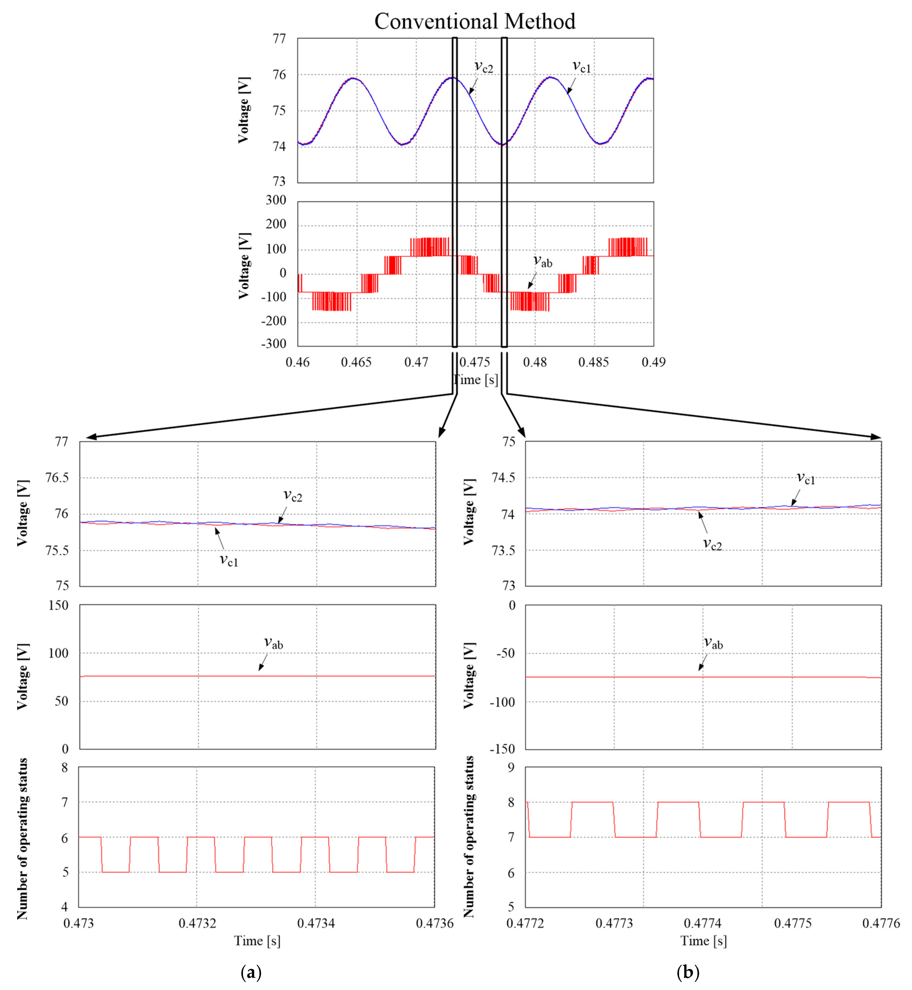
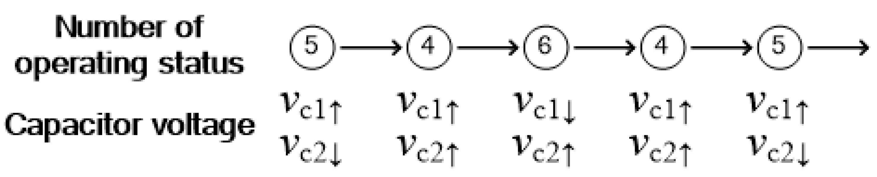
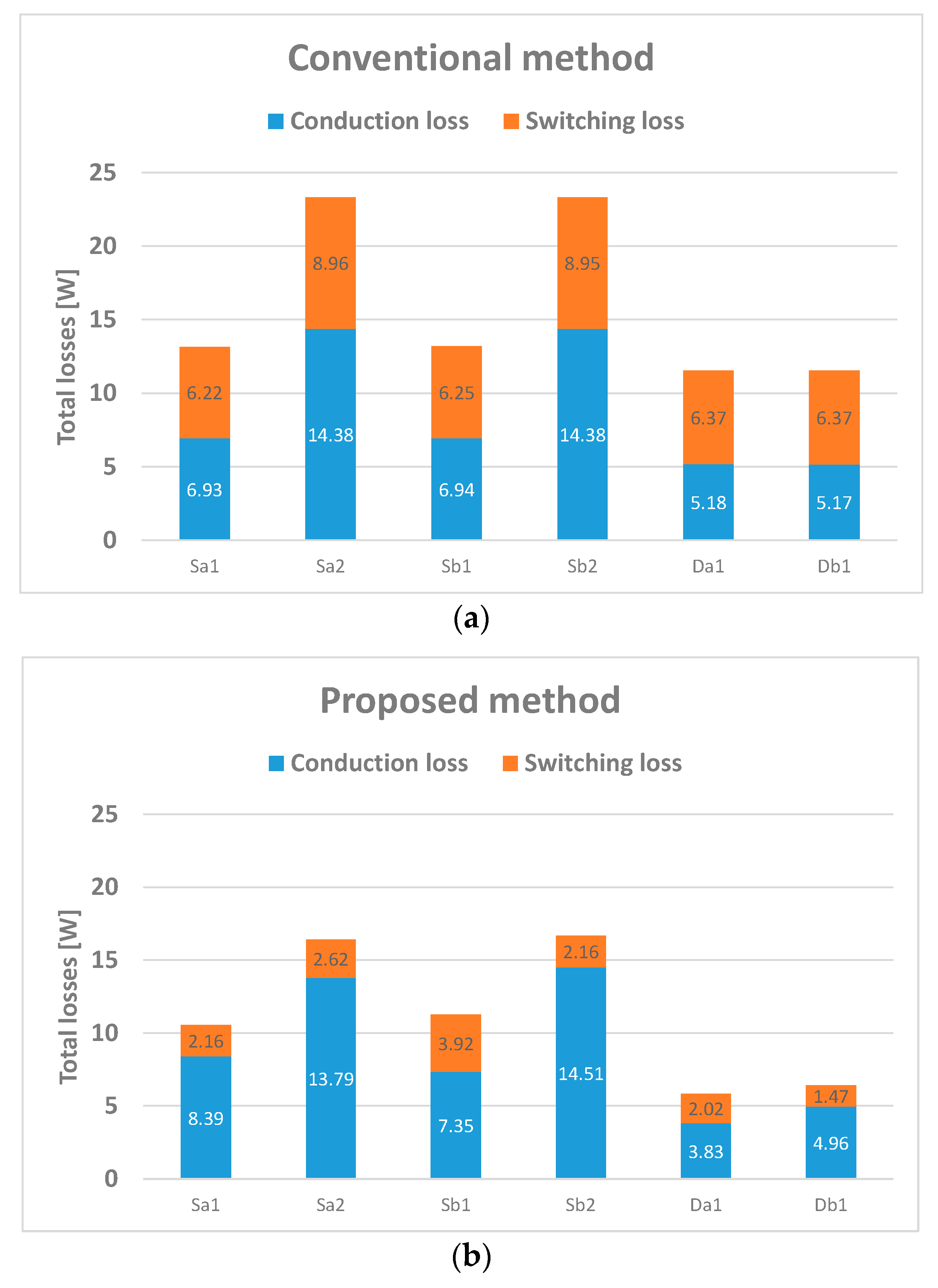
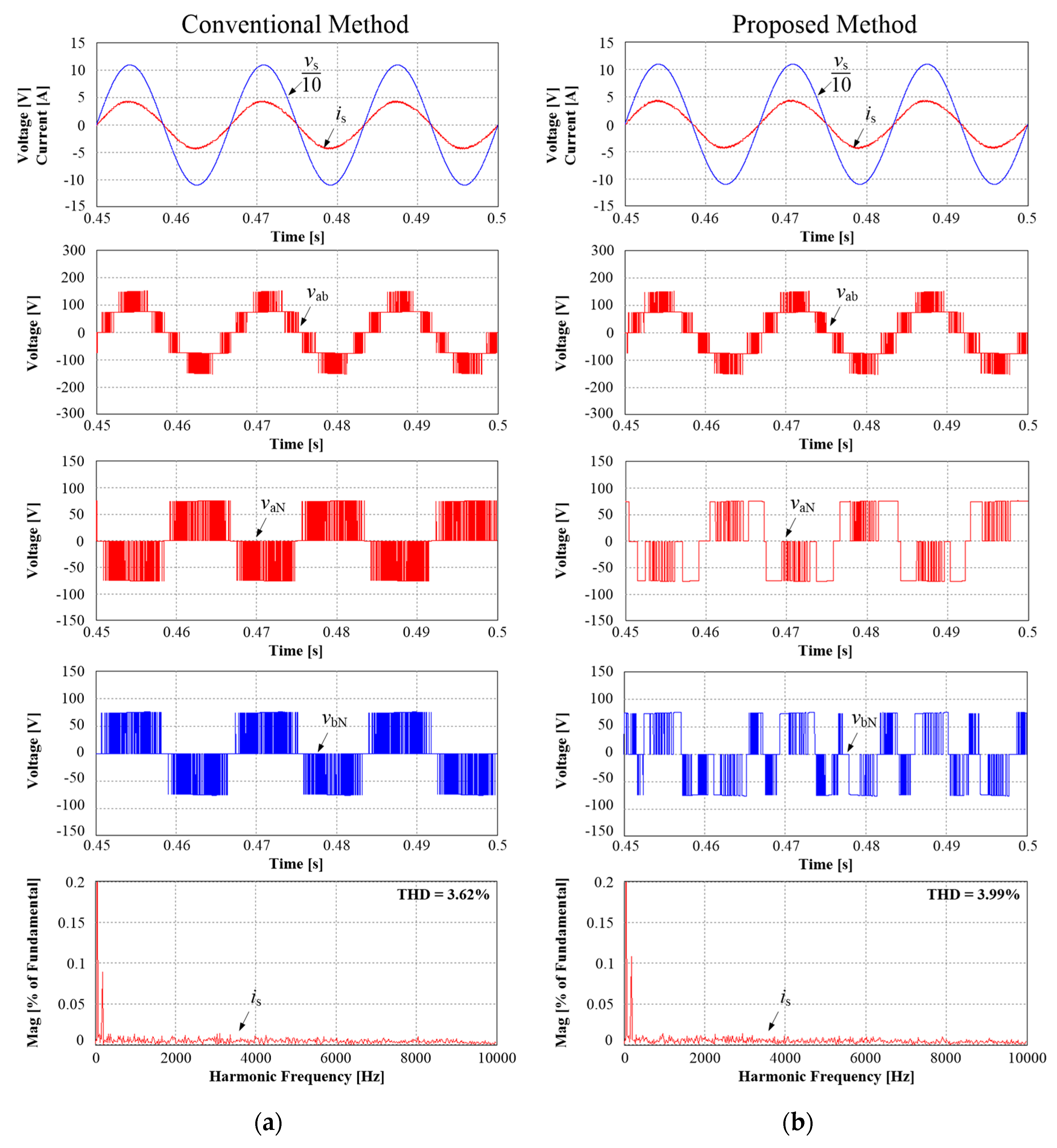
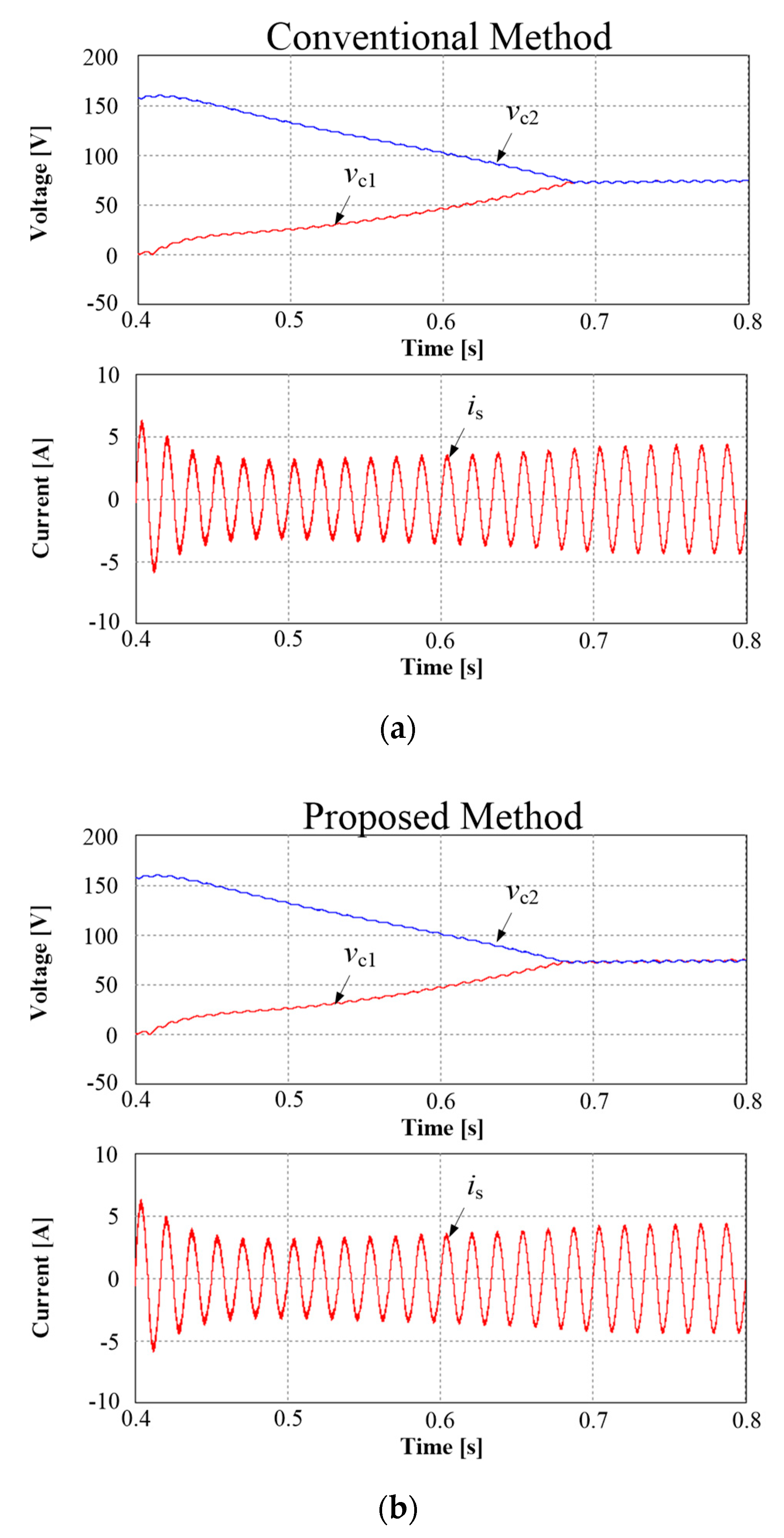
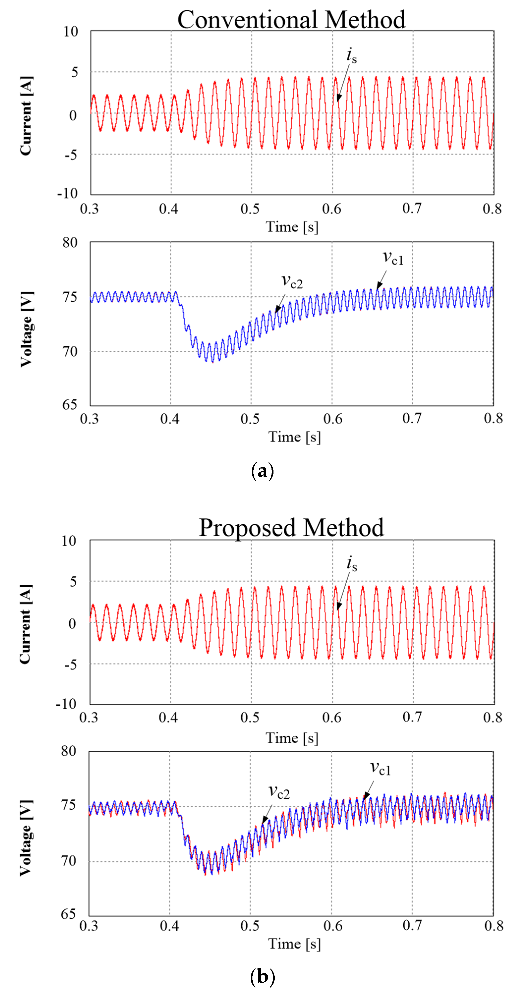
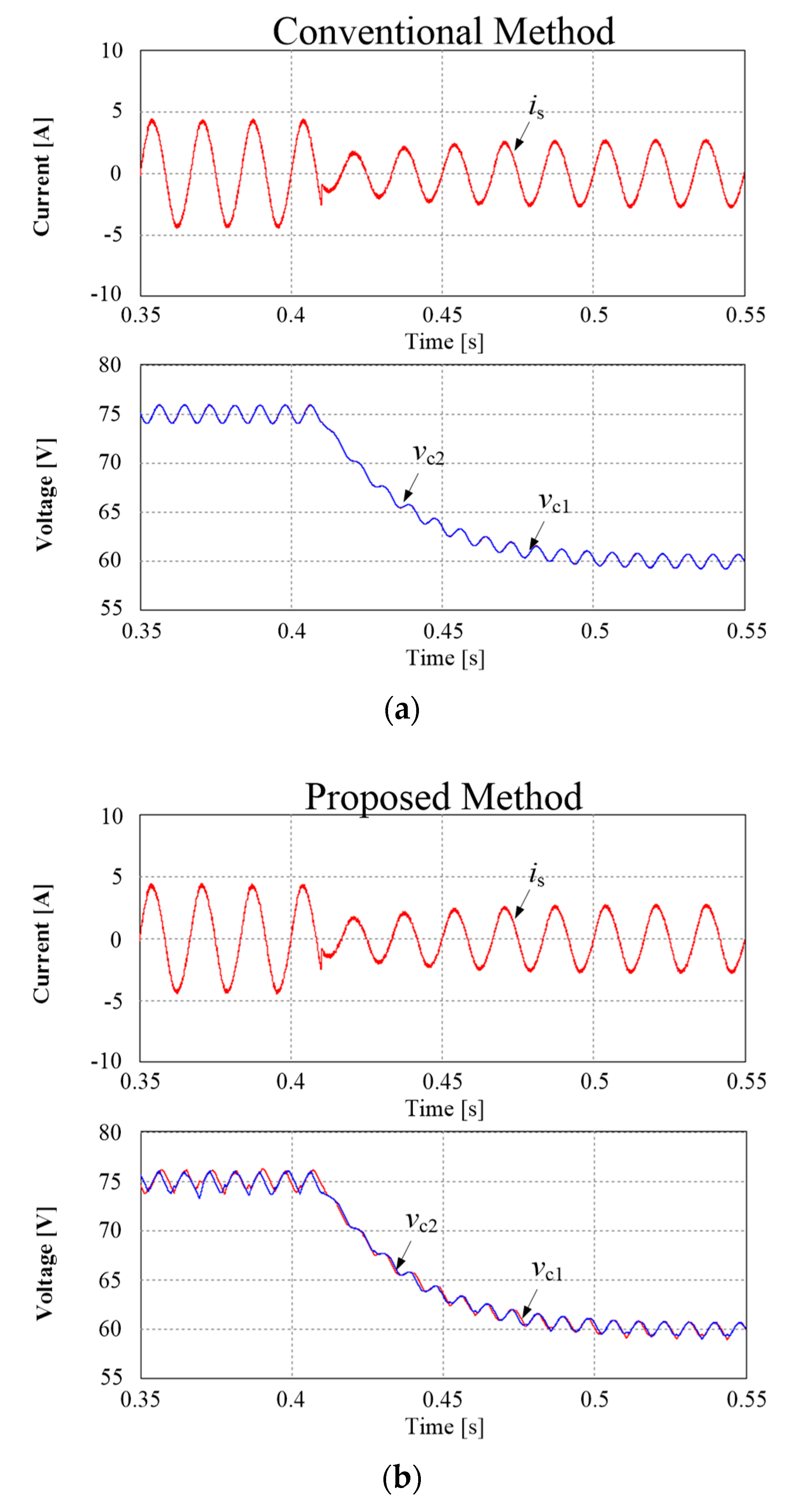
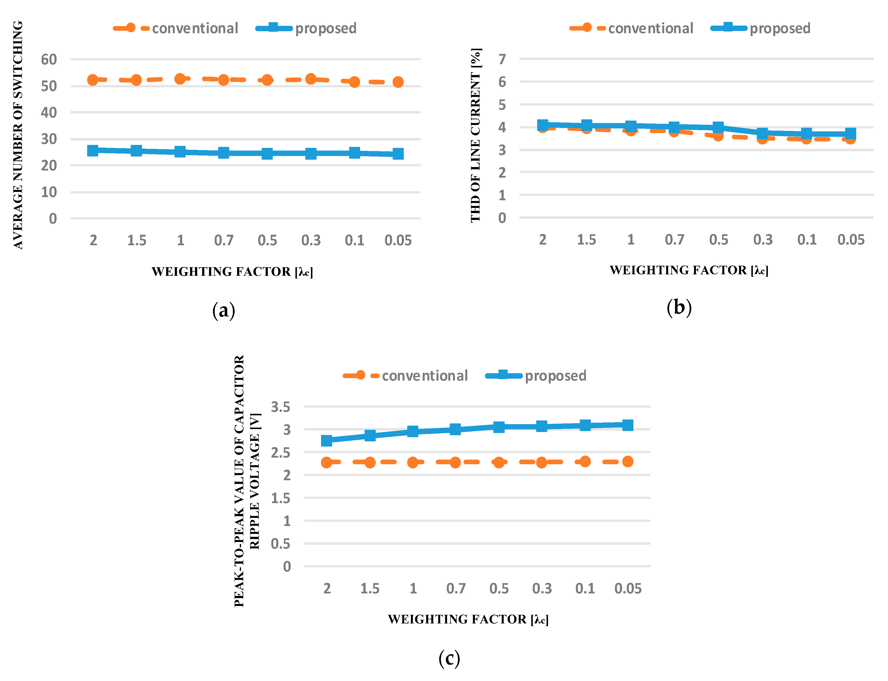
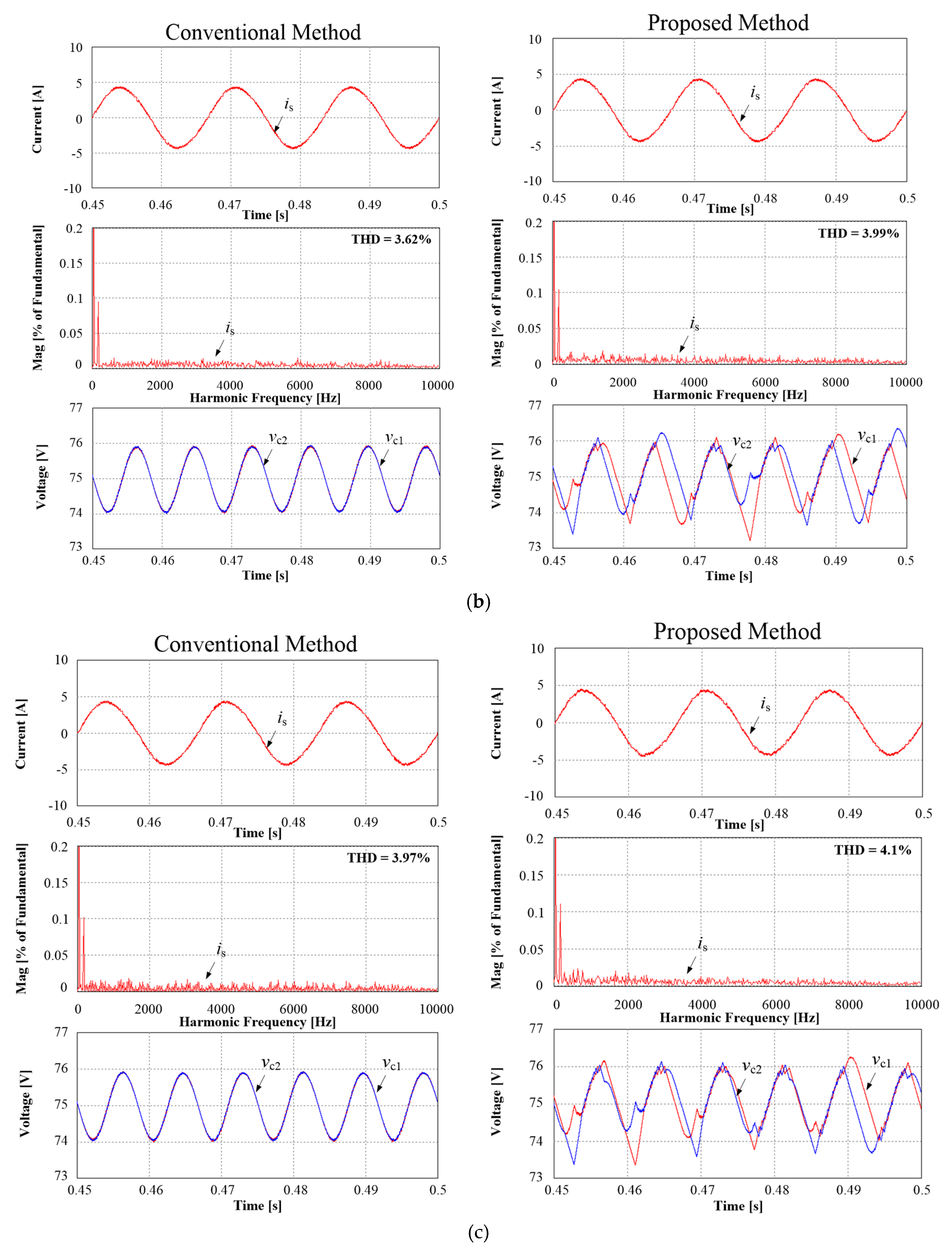
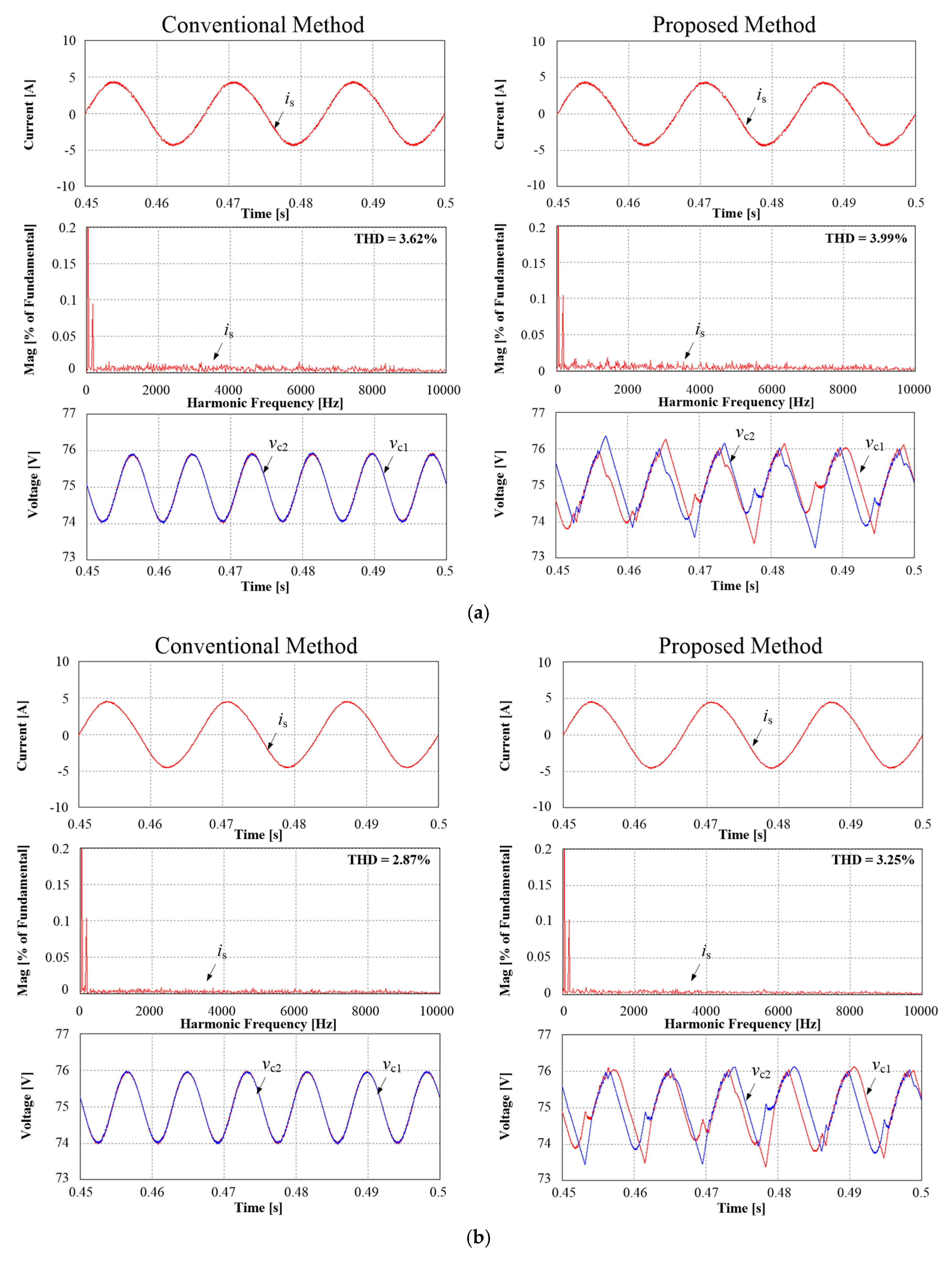
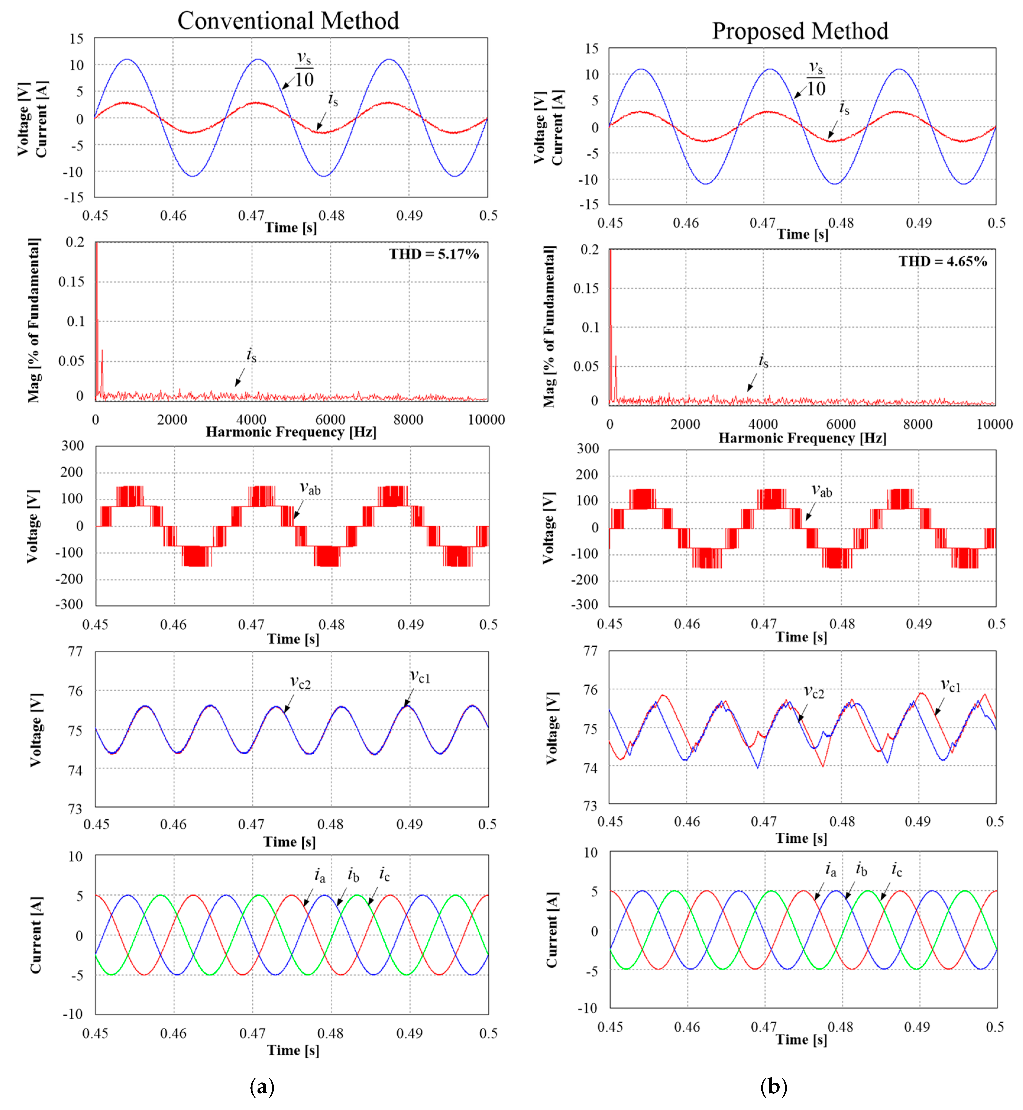
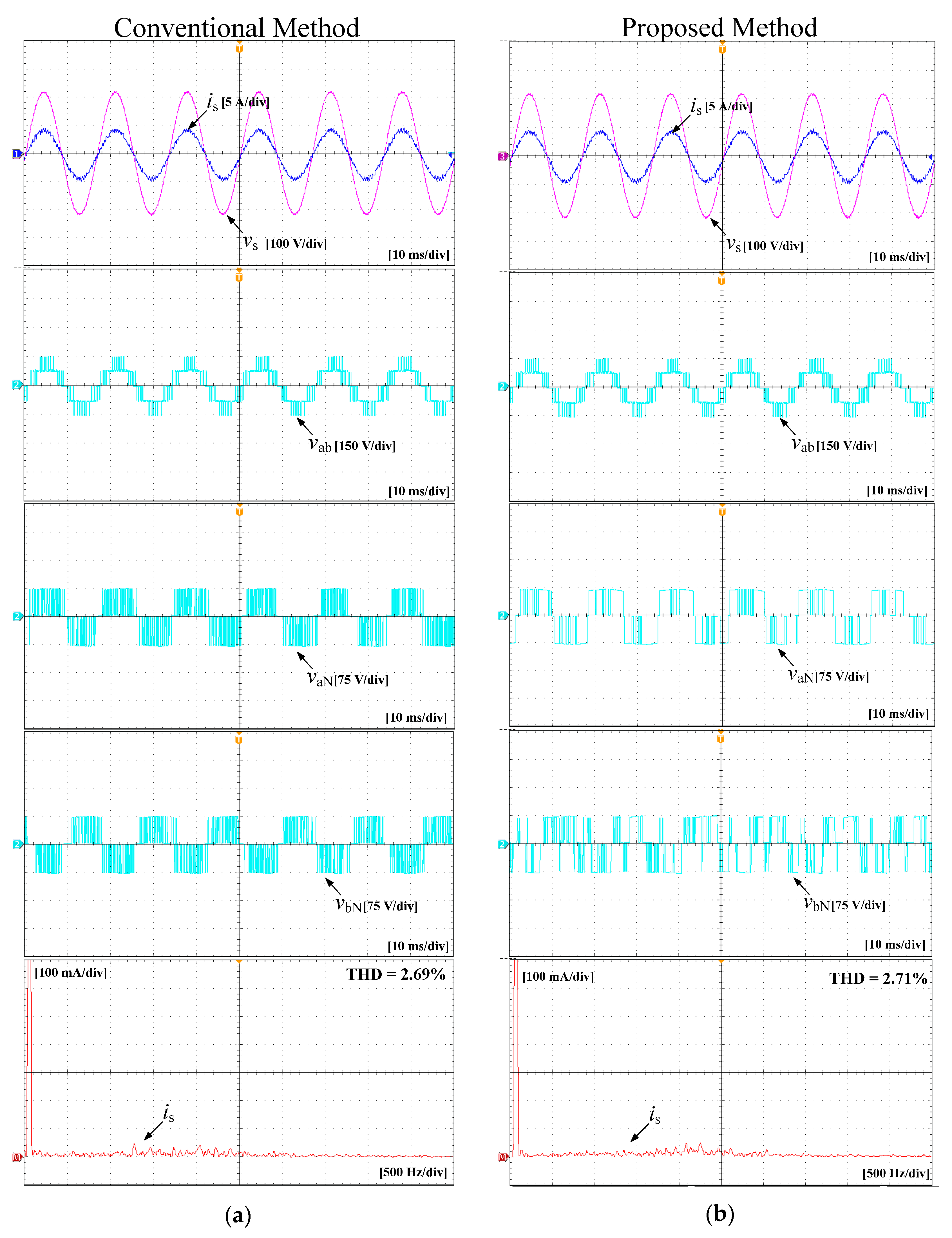
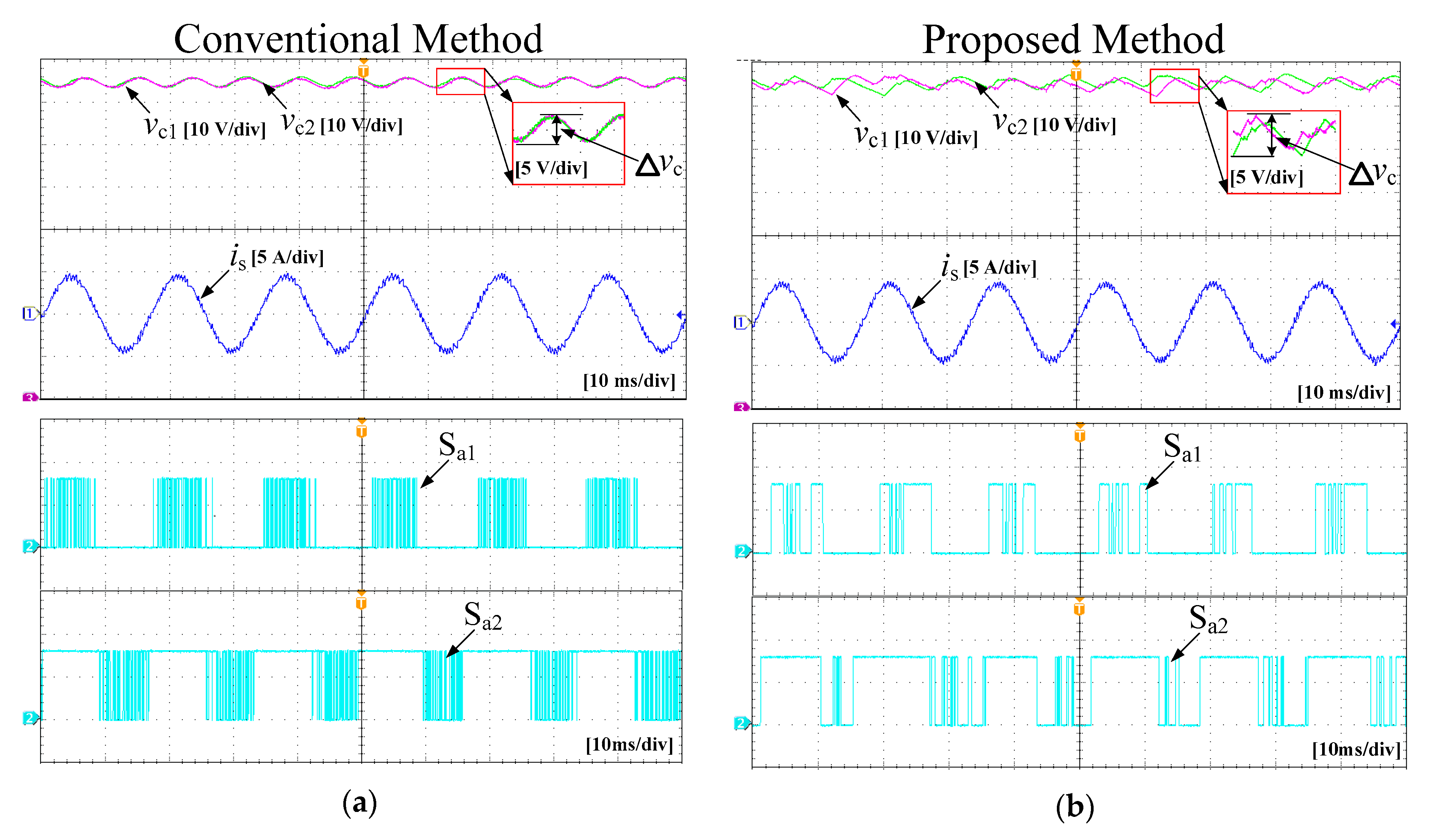
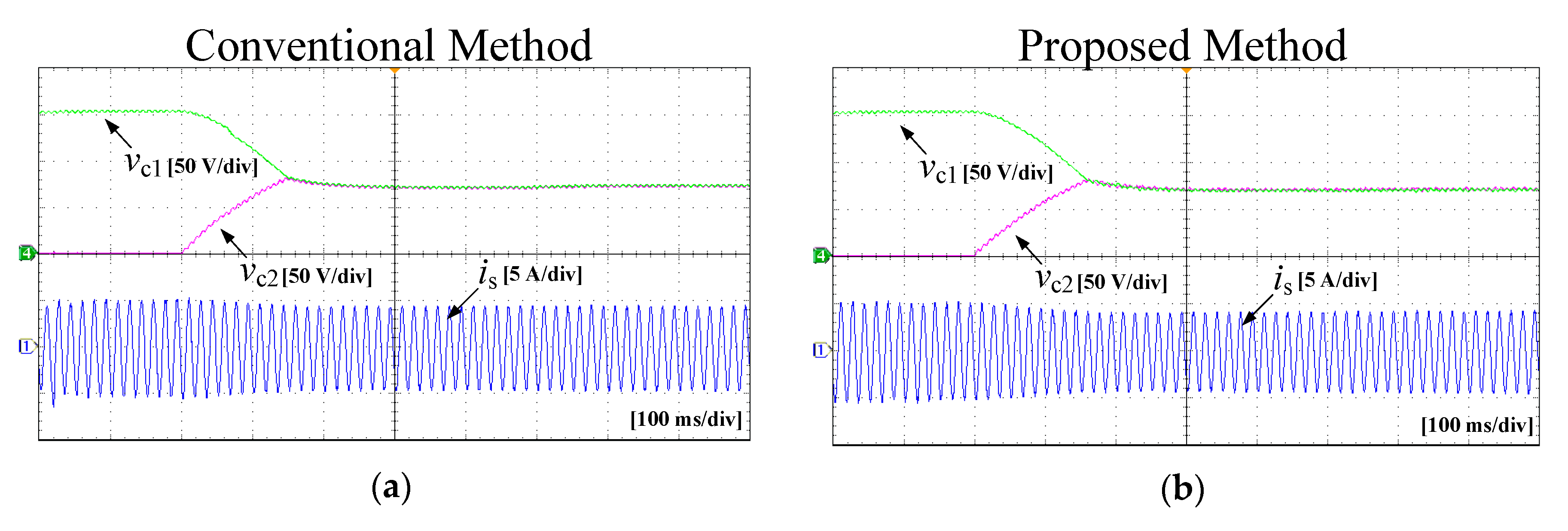
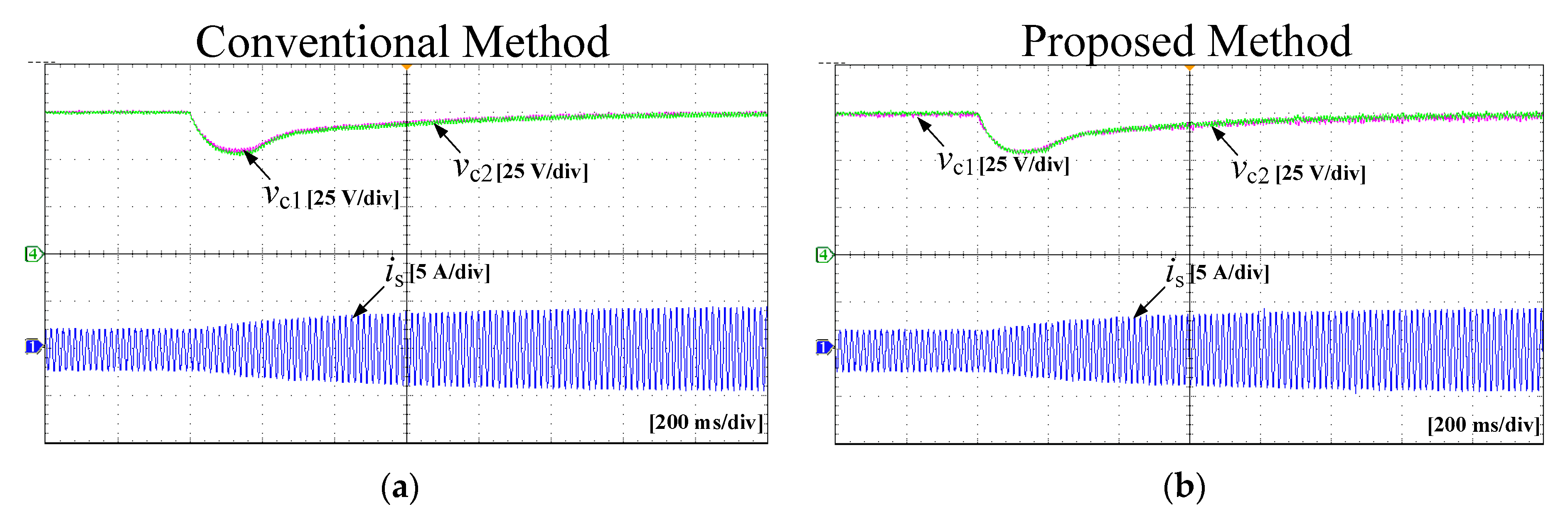
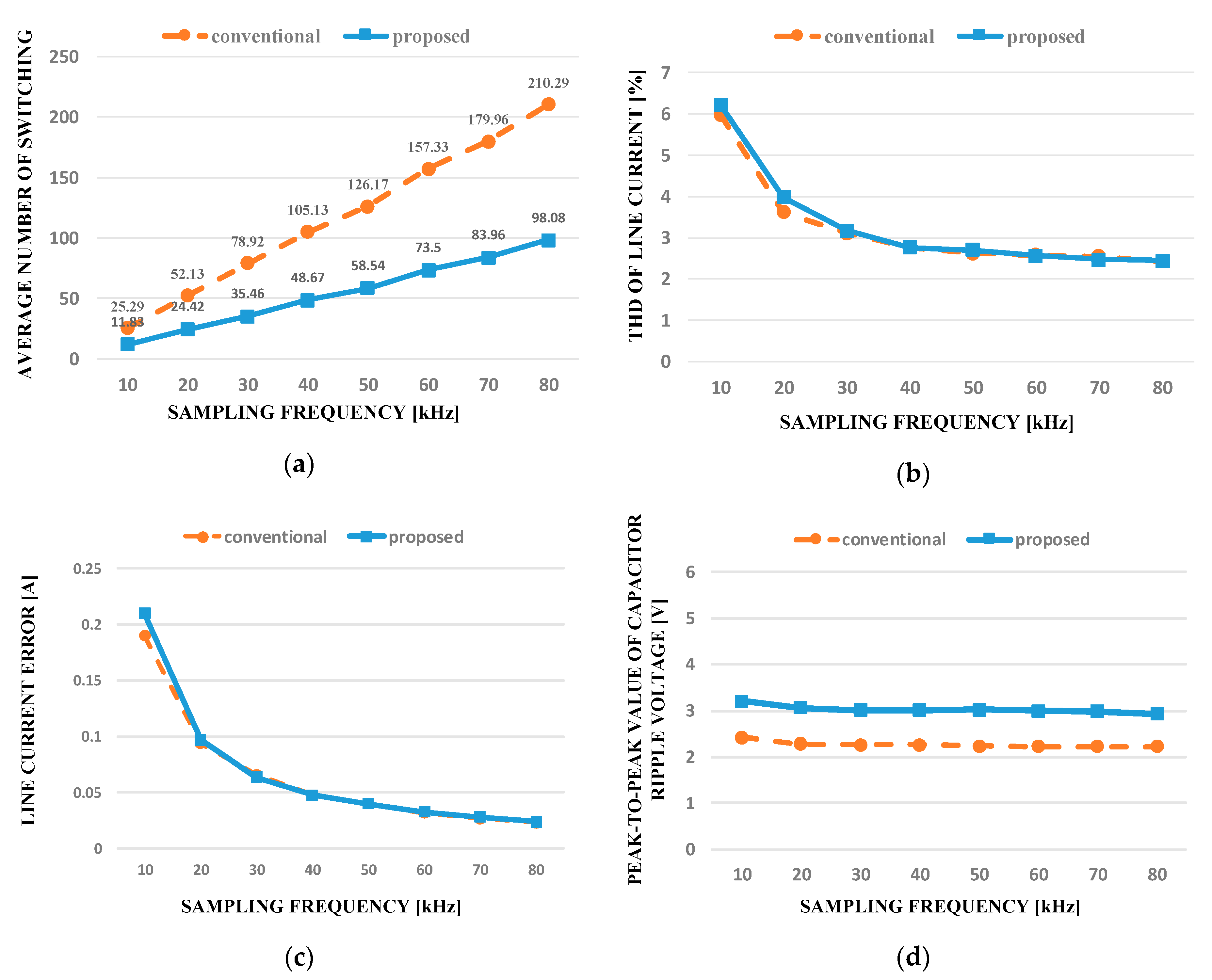
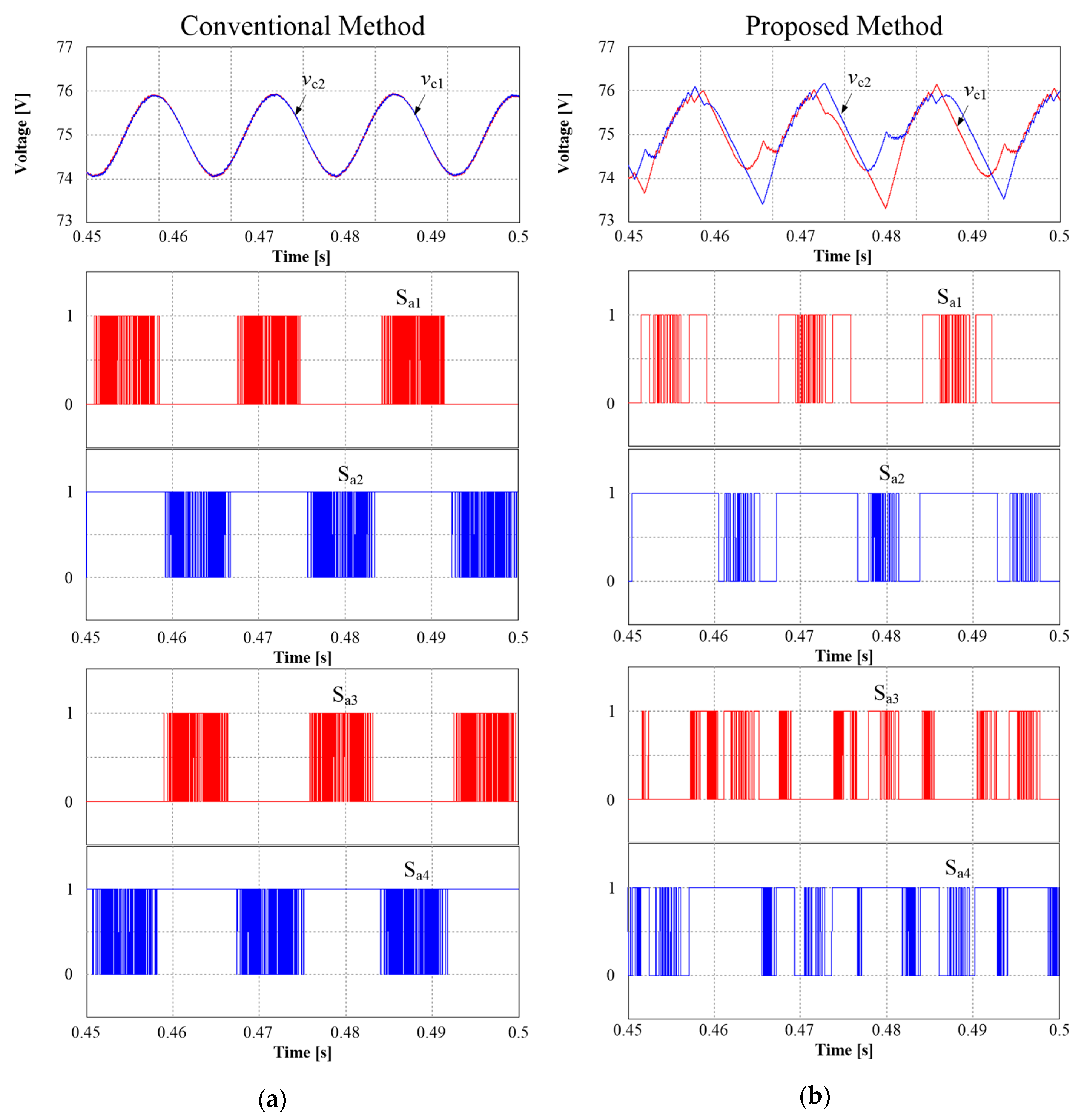
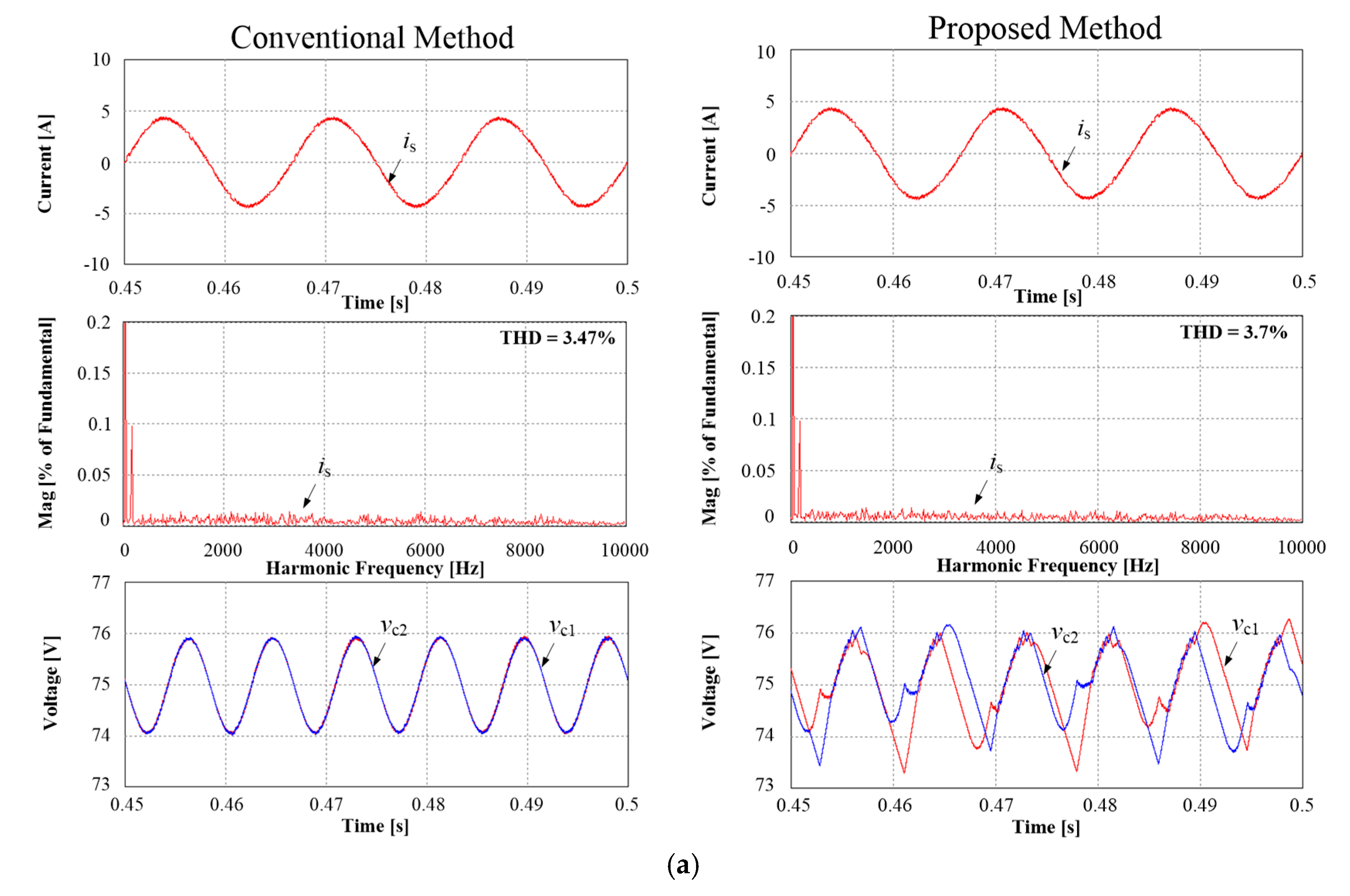
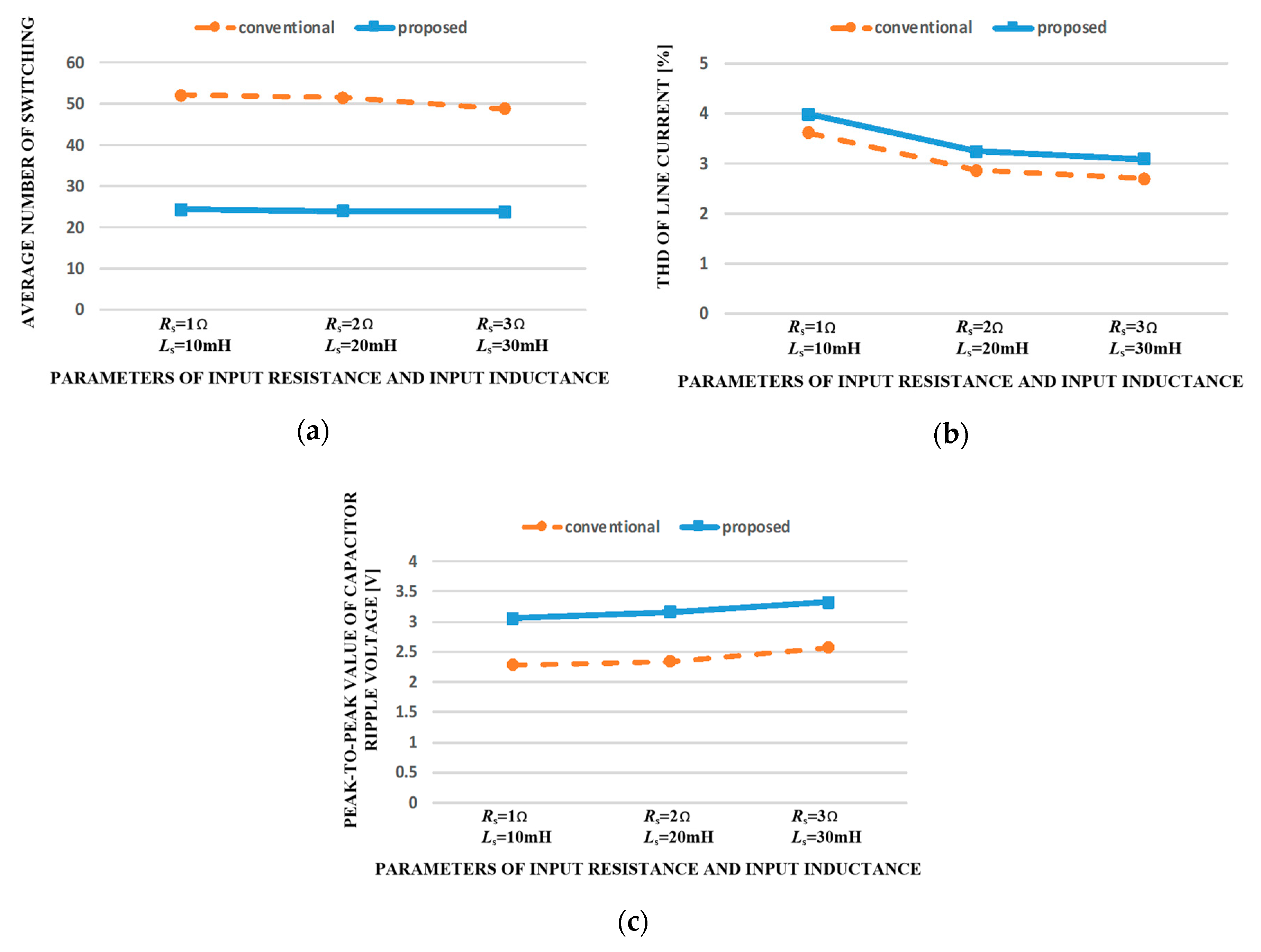
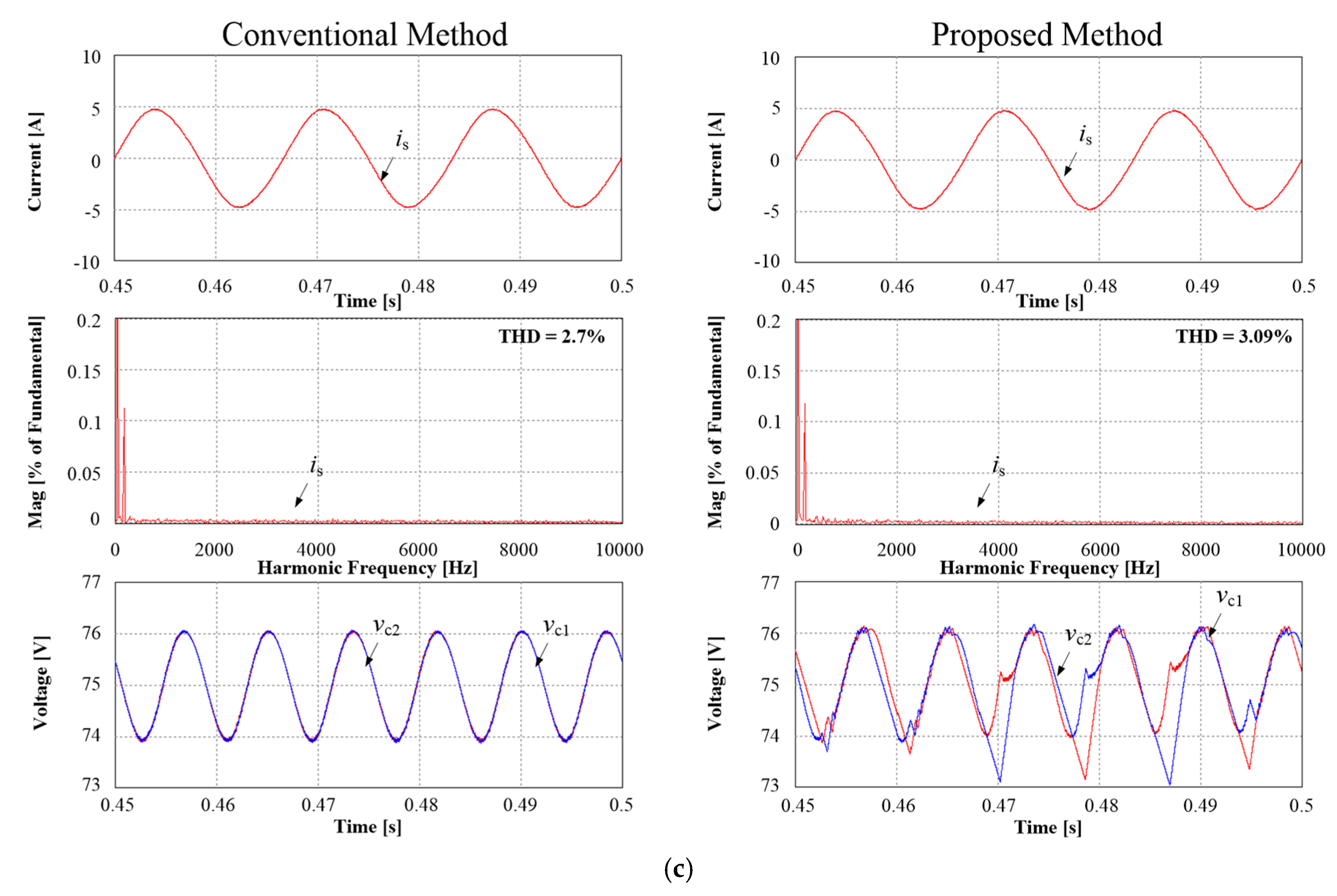
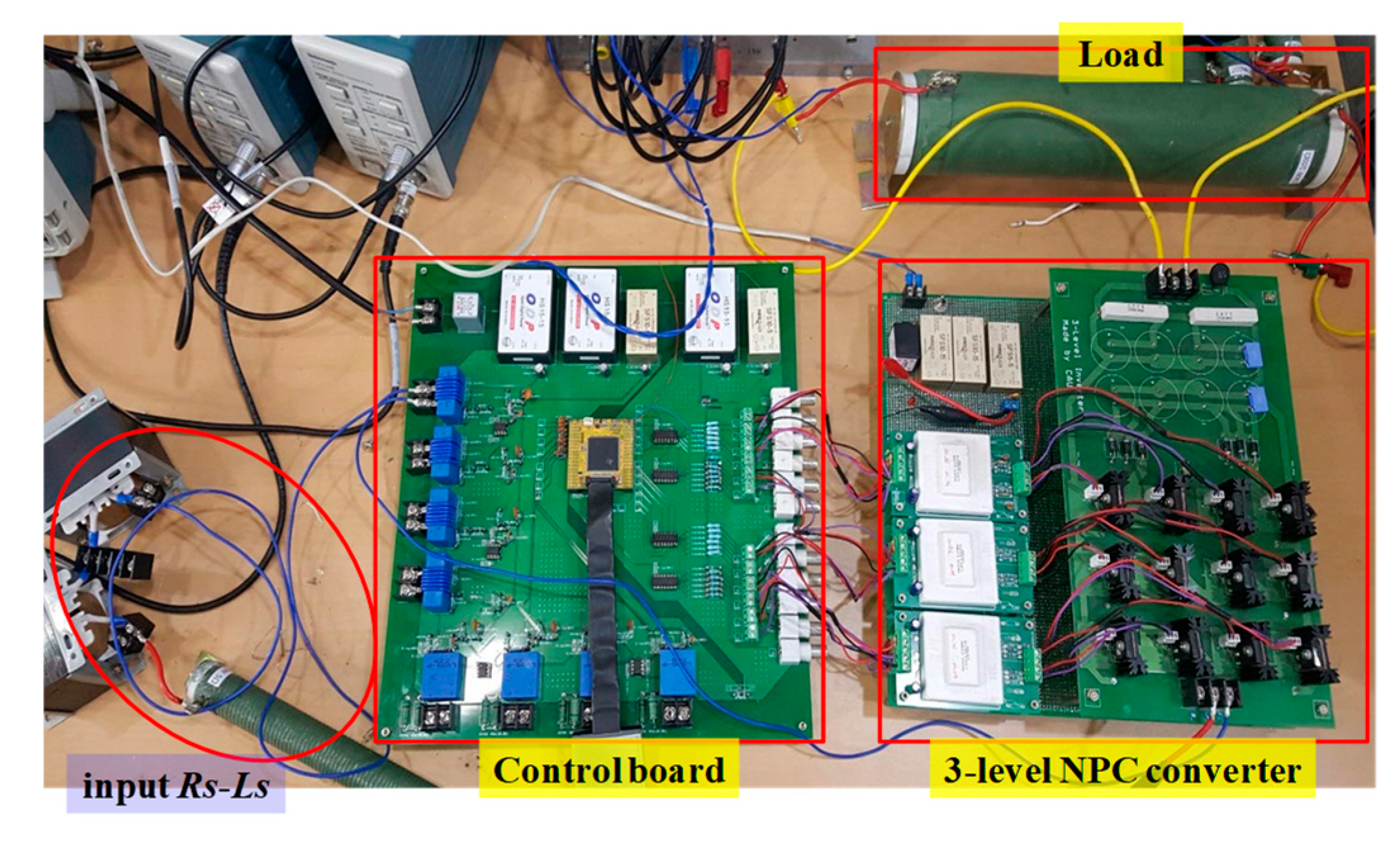
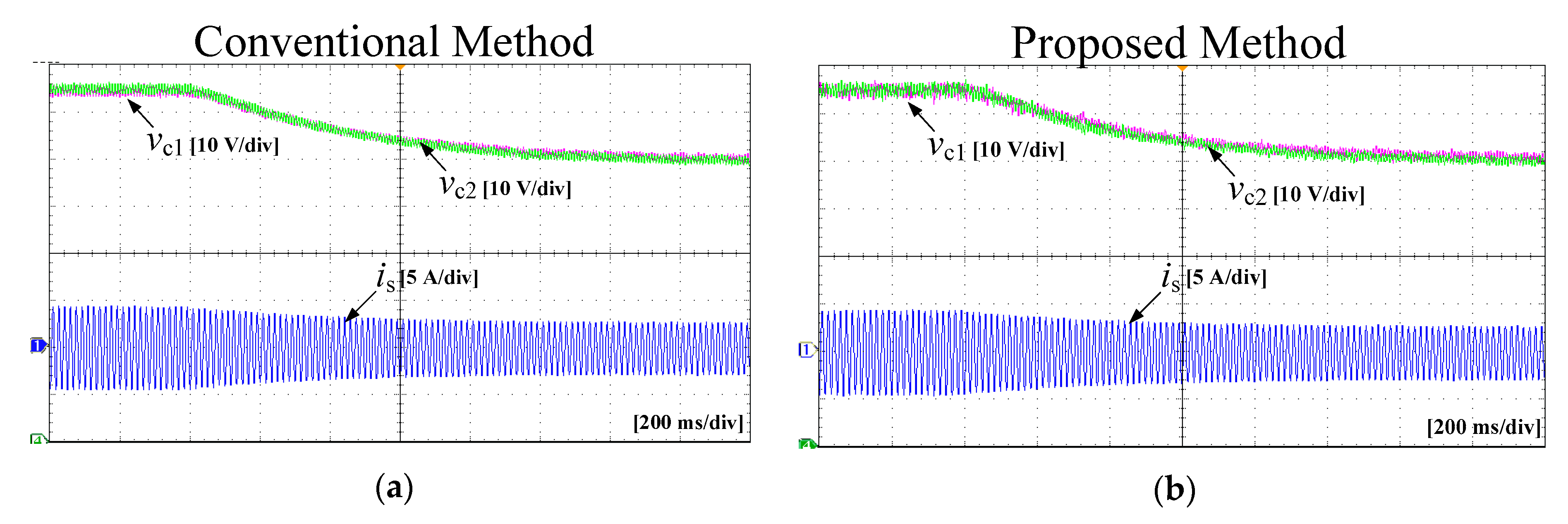
4. Simulation and Experimental Results

In order to demonstrate the proposed method, a single-phase three-level NPC converter with the proposed method was operated at vs = 110 V, Vdc = 150 V, Ts = 50 μs, RL = 100 Ω, Rs = 1 Ω, and Ls = 10 mH. The weighting factor λc = 0.5 in (11) was used for both the conventional and the proposed methods. Figure 8 shows simulation waveforms of the source current (is), source voltage (vs), line-to-line converter input voltage (vab), converter pole voltages (t), and frequency spectrum of the input current (is) obtained by the conventional and the proposed methods.
It is seen that the proposed method, operated with only a consideration of the reduced number of commutations, and the conventional method, using all possible switching states, make the source voltage and the source current in phase. This yields a unity power factor. It is noted that the source current and the ac line-to-line converter voltage generated by both methods are almost the same. On the other hand, the converter pole voltages of the proposed method are different from those of the conventional method because of the reduced number of switchings. It is seen that the pole voltage of the proposed method has a lower number of commutations than the conventional method owing to the reduced switching operations of the proposed method. From the frequency spectrum waveforms, it can be shown that the two methods represent almost the same current THD values. Therefore, the proposed method can reduce the number of switchings and the switching losses without deteriorating the quality of the ac current waveform in comparison with the conventional method.
Figure 9 shows simulation waveforms of the upper and the lower capacitor voltages (vc1 and vc2) and switching patterns of the four upper switches (Sa1, Sa2, Sb1, and Sb2) during the steady state as obtained by the conventional and proposed methods. In Figure 9a, obtained by the conventional MPC method using all possible switching states, the two capacitor voltages with the NP voltage controlled by the redundant switching states are almost equal with an avoidable oscillation at a certain voltage boundary ΔVC.
In the proposed method, as shown in Figure 9b, the converter is operated with only a consideration of the reduced number of commutations. It is clearly seen from the switching patterns that the proposed method yields a reduced number of switchings compared with the conventional method. This can lead to a decreased number of switching losses and higher efficiency. In addition, in the proposed method of Figure 9b, the NP voltage balance is well regulated without a continuous increase or decrease in the capacitor voltages, whereas the peak-to-peak ripple voltages of the two capacitors obtained by the proposed method are slightly increased compared with those of the conventional method. The number of switchings and switching losses of the proposed method were reduced by almost half in comparison with the conventional method.
Figure 10 shows simulation waveforms of the two methods when imbalance conditions of the capacitor voltages, which were intentionally generated, occur. Both the conventional and proposed methods can balance the capacitor voltages, as shown in Figure 10. It is seen that the proposed method, using a reduced number of possible switching states for a reduced number of commutations, can yield an NP voltage balance at almost the same speed as the conventional method.
Figure 11 and Figure 12 show simulation waveforms of step changes of the load resistance and the dc load voltage obtained by the two methods. It is seen that the proposed method achieves dynamic responses as quickly as the conventional method despite the reduced number of possible switching states to decrease the number of switching losses.
Effects of the control parameter λc on performance were investigated, where Figure 13 shows the average number of switching, the THD values of line current, and the peak-to-peak values of capacitor ripple voltage of the conventional and the proposed methods, as a function of the weighting factor λc varying from 0.05 to 2. It is shown from Figure 13 that the proposed method results in much lower average number of switching and almost same THD values of the line currents in comparison with the conventional method, over the range of the varying weighting factor. Figure 14. depicts simulation results of ac source current, frequency spectrum of source current, and two capacitor voltages obtained by the conventional and the proposed methods with weighting factor λc = 0.05, λc = 0.5, and λc = 2, respectively. The peak-to-peak value of the two capacitor ripple voltages of the proposed method is slightly increased compared with that of the conventional method, with the trade-off with the reduced number of switching and the consequently decreased switching losses. It is seen that the proposed method with the three different weighting factors regulates the sinusoidal input current well and maintains the two capacitor voltage balancing, even with the lower switching operations than the conventional method.
Performances with larger input resistance and input inductance were investigated. Figure 15 shows the average number of switching, the THD values of line current, and the peak-to-peak values of capacitor ripple voltage of the conventional and the proposed methods, for several values of the input resistance and the input inductance. It is shown from Figure 15 that the proposed method results in much lower average number of switching and almost same THD values of the line currents in comparison with the conventional method, for the different input parameters. Figure 16. depicts simulation results of ac source current, frequency spectrum of source current, and two capacitor voltages obtained by the conventional and the proposed methods with the three different input resistances and input inductances. The peak-to-peak value of the two capacitor ripple voltages of the proposed method is slightly increased compared with that of the conventional method, with the trade-off with the reduced number of switching and the consequently decreased switching losses. It is seen that the proposed method with the three different input parameters regulates the sinusoidal input current well and maintains the two capacitor voltage balancing, even with the lower switching operations than the conventional method.
The single-phase three-level NPC converter operated with the proposed method was tested with a nonlinear load, which is a three-phase voltage source inverter with a fundamental frequency of 80 Hz as shown in Figure 17. For the purpose of comparison, the simulation results obtained by the conventional method were also included. It is seen from Figure 18 that the single-phase three-level NPC converter with the proposed method well regulates the sinusoidal source current in phase with the source voltage with a low THD value, even with a nonlinear load. In addition, the two capacitor voltages of the proposed method are balanced in a case of the nonlinear load as the same as the linear load, as shown in Figure 18.
A prototype of a single-phase three-level NPC converter, shown in Figure 19, was fabricated in a laboratory to prove the proposed method. The conventional and proposed methods were implemented using a DSP board (TMS320F28335). To compare the performance of the two methods, experiments were conducted under the same conditions as the simulation. Figure 20 shows experimental waveforms of the source voltage/current, converter input voltage, each pole voltage, and an FFT analysis of the source current for the conventional method and the proposed method during steady-state conditions.
As in the simulation, the proposed method shows almost the same source current and converter input voltage waveforms as the conventional method. In addition, the proposed method through the FFT analysis shows performance that is very similar to that of the conventional method. On the other hand, as shown in Figure 20, the proposed method has a quite different pole voltage from the conventional method owing to the reduced number of switchings.
Figure 21 shows the upper and lower capacitor voltages, source current, and switching state in the steady state. As shown in Figure 21, the proposed method reduces the number of switchings in comparison with the conventional method. In addition, the NP voltage balance in the proposed method is well regulated without a continuous increase or decrease in the capacitor voltages, whereas the peak-to-peak ripple voltages of the two capacitors obtained by the proposed method is slightly increased compared with the conventional method.
In Figure 22, experimental waveforms of the two methods are shown when imbalanced NP voltage conditions of the capacitor voltages, which are intentionally generated, occur. Both the conventional and proposed methods can balance the capacitor voltages, as shown in Figure 22. This is the same as the simulation results of Figure 10. It is seen that the proposed method, using a reduced number of possible switching states for a reduced number of commutations, can yield an NP voltage balance at almost the same speed as the conventional method. Figure 23 and Figure 24 show experimental waveforms of step changes of the load resistance and the dc load voltage obtained by the two methods. It is seen that the proposed method achieves dynamic responses as quickly as the conventional method despite the reduced number of possible switching states to decrease the number of switching losses.

5. Conclusions

This paper proposed a highly efficient algorithm with a reduced number of switchings and low switching losses for single-phase three-level NPC converters based on an MPC method with a decreased number of commutations of switches. The proposed method pre-excludes, from the candidates for possible future switching states, the switching states that yield more than two commutations in the next sampling period. As a result, the proposed technique can reduce the number of switchings and the switching losses by utilizing switching states involving no commutation or only one commutation at every sampling instant for single-phase three-level NPC converters. In addition, the developed method does not deteriorate the input current quality or input power factor despite the reduced switching numbers and losses. Although the proposed method slightly increases the peak-to-peak variations of the two dc capacitor voltages at the expense of reduced commutation, the increased voltage variation is not high. Thus, the proposed method can obtain high efficiency and low switching losses at the expense of slightly increased peak-to-peak variations of the NP voltage. Simulations and experimental results were presented to verify the effectiveness of the proposed method.

Author Contributions

All authors contributed to this work by collaboration.

Acknowledgments

This research was supported by the National Research Foundation of Korea (NRF) grant funded by the Korean government (MSIP) (2017R1A2B4011444) and the Human Resources Development (No.20174030201810) of the Korea Institute of Energy Technology Evaluation and Planning (KETEP) grant funded by the Korea government Ministry of Trade, Industry and Energy.

Conflicts of Interest

The authors declare no conflict of interest.

Nomenclature

Abbreviations
EMIElectromagnetic interference
NPCNeutral point clamped
CBPWMCarrier-based pulse width modulation
PIProportional and integral
NPNeutral point
MPCModel predictive control
THDTotal harmonic distortion
IGBTInsulated gate bipolar transistor
Variables
SaOperating status of a-phase
SbOperating status of b-phase
vaSource voltage
iaSource current
i a * Reference source current
R s Input resistance
L s Input inductance
v a b Line-to-line source voltage
v a N Phase voltage of a-phase
v b N Phase voltage of b-phase
C 1 Output capacitance in upper capacitor
C 2 Output capacitance in lower capacitor
i u Current of upper dc-bus bar
i l Current of lower dc-bus bar
R L Output load resistance
V d c Output dc voltage
gCost function
λ c Weighting factor
T s Sampling period

References

  1. Portillo, R.; Prats, M.M.; Leon, J.I.; Sanchez, J.A.; Carrasco, J.M.; Galvan, E.; Franquelo, L.G. Modeling strategy for back-to-back three-level converters applied to high-power wind turbines. IEEE Trans. Ind. Electron. 2006, 53, 1483–1491. [Google Scholar] [CrossRef]
  2. Alepuz, S.; Busquets-Monge, S.; Bordonau, J.; Gago, J.; Gonzalez, D.; Balcells, J. Interfacing renewable energy sources to the utility grid using a three-level inverter. IEEE Trans. Ind. Electron. 2006, 53, 1504–1511. [Google Scholar] [CrossRef]
  3. Stala, R. Application of balancing circuit for DC-link voltages balance in a single-phase diode-clamped inverter with two three-level legs. IEEE Trans. Ind. Electron. 2011, 58, 4185–4195. [Google Scholar] [CrossRef]
  4. Song, W.; Feng, X.; Smedley, K. A carrier-based PWM strategy with the offset voltage injection for single-phase three-level neutral-point-clamped converters. IEEE Trans. Power Electron. 2013, 28, 1083–1095. [Google Scholar] [CrossRef]
  5. Choi, U.-M.; Lee, H.-H.; Lee, K.-B. Simple neutral-point voltage control for three-level inverters using a discontinuous pulse width modulation. IEEE Trans. Energy Convers. 2013, 28, 434–443. [Google Scholar] [CrossRef]
  6. Song, W.; Wang, S.; Xiong, C.; Ge, X.; Feng, X. Single-phase three-level space vector pulse width modulation algorithm for grid-side railway tractionconverter and its relationship of carrier-based pulse width modulation. IET Electr. Syst. Transp. 2014, 14, 78–87. [Google Scholar] [CrossRef]
  7. Freitas, I.S.D.; Bandeira, M.M.; Barros, L.D.M.; Jacobina, C.B.; Santos, E.C.D.; Salvadori, F.; Silva, S.A.D. A carrier-based PWM technique for capacitor voltage balancing of single-phase three-level neutral-point-clamped converters. IEEE Trans. Ind. Appl. 2015, 51, 3227–3235. [Google Scholar] [CrossRef]
  8. Habibullah, M.; Lu, D.D.; Xiao, D.; Fletcher, J.E.; Rahman, M.F. Predictive torque control of induction motor sensorless drive fed by a 3L-NPC inverter. IEEE Trans. Ind. Inf. 2017, 13, 60–70. [Google Scholar] [CrossRef]
  9. Yaramasu, V.; Wu, B. Predictive control of a three-level boost converter and an NPC inverter for high-power PMSG-based medium voltage wind energy conversion systems. IEEE Trans. Power Electron. 2014, 29, 5308–5322. [Google Scholar] [CrossRef]
  10. Acuna, P.; Moran, L.; Rivera, M.; Aguilera, R.; Burgos, R.; Agelidis, V.G. A single-objective predictive control method for a multivariable single-phase three-level NPC converter-based active power filter. IEEE Trans. Ind. Electron. 2015, 62, 4598–4607. [Google Scholar] [CrossRef]
  11. Song, W.; Ma, J.; Zhou, L.; Feng, X. Deadbeat predictive power control of single-phase three-level neutral-point-clamped converters using space-vector modulation for electric railway traction. IEEE Trans. Power Electron. 2016, 31, 1083–1095. [Google Scholar] [CrossRef]
  12. Acuna, P.; Aguilera, R.P.; Ghias, A.M.Y.M.; Rivera, M.; Baier, C.R.; Agelidis, V.G. Cascade-free model predictive control for single-phase grid-connected power converters. IEEE Trans. Ind. Electron. 2017, 64, 721–732. [Google Scholar] [CrossRef]
  13. Deng, Y.; Li, J.; Shin, K.H.; Viitanen, T.; Saeedifard, M.; Harley, R.G. Improved modulation scheme for loss balancing of three-level active NPC converters. IEEE Trans. Power Electron. 2017, 32, 2521–2532. [Google Scholar] [CrossRef]
  14. Jing, X.; He, J.; Demerdash, N.A.O. Loss balancing SVPWM for active NPC converters. In Proceedings of the 2014 IEEE Applied Power Electronics Conference and Exposition—APEC 2014, Fort Worth, TX, USA, 16–20 March 2014. [Google Scholar]
  15. Pulikanti, S.; Dahidah, M.S.A.; Agelidis, V. Voltage balancing control of three-level active NPC converter using SHE-PWM. IEEE Trans. Power Deliv. 2011, 26, 258–267. [Google Scholar] [CrossRef]
  16. Bruckner, T.; Bernet, S.; Guldner, H. The active NPC converter and its loss-balancing control. IEEE Trans. Ind. Electron. 2005, 52, 855–868. [Google Scholar] [CrossRef]
  17. Floricau, D.; Gateau, G.; Leredde, A.; Teodorescu, R. The efficiency of three-level active NPC converter for different PWM strategies. In Proceedings of the 2009 13th European Conference on Power Electronics and Applications, Barcelona, Spain, 8–10 September 2009. [Google Scholar]
  18. Bruckner, T.; Bernet, S.; Steimer, P. Feedforward loss control of three-level active NPC converters. IEEE Trans. Ind. Appl. 2007, 43, 1588–1596. [Google Scholar] [CrossRef]
  19. Brückner, T.; Bernet, S. Loss balancing in three-level voltage source inverters applying active NPC switches. In Proceedings of the IEEE Power Electronics Specialists Conference (PESC), Vancouver, BC, Canada, 17–21 June 2001; pp. 1135–1140. [Google Scholar]
  20. Ma, L.; Kerekes, T.; Rodriguez, P.; Jin, X.; Teodorescu, R.; Liserre, M. A new PWM strategy for grid-connected half-bridge active NPC converters with losses distribution balancing mechanism. IEEE Trans. Power Electron. 2015, 30, 5331–5340. [Google Scholar] [CrossRef]
  21. Jiao, Y.; Lee, F.C. New modulation scheme for three-level active neutral-point-clamped converter with loss and stress reduction. IEEE Trans. Ind. Electron. 2015, 62, 5468–5479. [Google Scholar] [CrossRef]
  22. Habibullah, M.; Lu, D.D.; Xiao, D.; Rahman, M.F. Finite-state predictive torque control of induction motor supplied from a three-level NPC voltage source inverter. IEEE Trans. Power Electron. 2017, 32, 479–489. [Google Scholar] [CrossRef]
  23. Vargas, R.; Ammann, U.; Rodriguez, J. Predictive approach to increase efficiency and reduce switching losses on matrix converters. IEEE Trans. Power Electron. 2009, 24, 894–902. [Google Scholar] [CrossRef]
  24. Vargas, R.; Rodriguez, J.; Rojas, C.A.; Rivera, M. Predictive control of an induction machine fed by a matrix converter with increased efficiency and reduced common-mode voltage. IEEE Trans. Energy Convers. 2014, 29, 473–485. [Google Scholar]
  25. Vatani, M.; Bahrani, B.; Saeedifard, M.; Hovd, M. Indirect finite control set model predictive control of modular multilevel converters. IEEE Trans. Smart Grid 2015, 6, 1520–1529. [Google Scholar] [CrossRef]
  26. Kwak, S.; Park, J. Switching strategy based on model predictive control of VSI to obtain high efficiency and balanced loss distribution. IEEE Trans. Power Electron. 2014, 29, 4551–4567. [Google Scholar] [CrossRef]
  27. Kwak, S.; Park, J. Predictive control method with future zero-sequence voltage to reduce switching losses in three-phase voltage source inverters. IEEE Trans. Power Electron. 2015, 30, 1558–1566. [Google Scholar] [CrossRef]
  28. Kukrer, O. Discrete-time current control of voltage-fed three-phase PWM inverters. IEEE Trans. Power Electron. 1996, 11, 260–269. [Google Scholar] [CrossRef]
  29. Hildetirand, F.B. Introduction to Numerical Analysis; McGraw-Hill: New York, NY, USA, 1956. [Google Scholar]
  30. Venkatraman, K.; Selvan, M.P.; Moorthi, S. Predictive current control of distribution static compensator for load compensation in distribution system. IET Gener. Transm. Distrib. 2016, 10, 2410–2423. [Google Scholar] [CrossRef]
  31. Kumar, C.; Mishra, M.K. Operation and control of an improved performance interactive DSTATCOM. IEEE Trans. Ind. Electron. 2015, 62, 6024–6034. [Google Scholar] [CrossRef]
Figure 1. Single-phase three-level NPC converter.
Energies 11 03524 g001
Figure 2. Simulation waveforms of conventional MPC method (a) during period with converter voltage vab fixed to Vdc/2 and (b) during period with converter input voltage vab fixed to −Vdc/2.
Energies 11 03524 g002
Figure 3. Simulation waveforms of proposed MPC method (a) during period with converter voltage vab fixed to Vdc/2 and (b) during period with converter input voltage vab fixed to −Vdc/2.
Energies 11 03524 g003
Figure 4. Simulation waveforms of proposed MPC method during period with converter voltage vab between Vdc/2 and Vdc.
Energies 11 03524 g004
Figure 5. Number of operating status and capacitor voltage behavior of proposed MPC method during period with converter voltage vab between Vdc/2 and Vdc.
Energies 11 03524 g005
Figure 6. Comparison results obtained by conventional MPC method and proposed method vs. sampling frequency: (a) number of switchings; (b) THD values of source currents; (c) current errors; and (d) peak-to-peak values of capacitor ripple voltages.
Energies 11 03524 g006
Figure 7. Loss comparison of (a) conventional method (b) proposed method.
Energies 11 03524 g007
Figure 8. Simulation results of ac source current (is), source voltage (vs), converter line-to-line voltage (vab), pole voltages (vaN, vbN), and frequency spectrum of input current (is) obtained by (a) conventional and (b) proposed methods.
Energies 11 03524 g008
Figure 9. Simulation results of upper and lower capacitor voltages (vc1, vc2) and switching patterns of four upper switches (Sa1, Sa2, Sb1, Sb2) during steady state in (a) conventional MPC method and (b) proposed MPC method.
Energies 11 03524 g009
Figure 10. Simulation results of capacitor voltages (vc1, vc2) and source current during imbalanced NP voltage conditions obtained by (a) conventional method and (b) proposed method.
Energies 11 03524 g010
Figure 11. Simulation results of capacitor voltages (vc1, vc2) and source current with step change of load resistor from 200 Ω to 100 Ω obtained by (a) conventional method and (b) proposed method.
Energies 11 03524 g011
Figure 12. Simulation results of capacitor voltages (vc1, vc2) and source current with step change of dc voltage from 150 V to 120 V obtained by (a) conventional method and (b) proposed method.
Energies 11 03524 g012
Figure 13. Effects of weighting factor λc varying from 0.05 to 2 on (a) average number of switching (b) THD of line current (c) peak-to-peak value of capacitor ripple voltage of the conventional and the proposed methods.
Energies 11 03524 g013
Figure 14. Simulation results of ac source current (is), frequency spectrum of input current (is), and capacitor voltages (vaN, vbN) obtained by the conventional and the proposed methods with weighting factor (a) λc = 0.05, (b) λc = 0.5, and (c) λc = 2.
Energies 11 03524 g014aEnergies 11 03524 g014b
Figure 15. Effects of input resistance and input inductance on (a) average number of switching (b) THD of line current (c) peak-to-peak value of capacitor ripple voltage of the conventional and the proposed methods.
Energies 11 03524 g015
Figure 16. Simulation results of ac source current (is), frequency spectrum of input current (is), and capacitor voltages (vaN, vbN) obtained by the conventional and the proposed methods with input parameters (a) Rs = 1 Ω and Ls = 10 mH (b) Rs = 2 Ω and Ls = 20 mH, and (c) Rs = 3 Ω and Ls = 30 mH.
Energies 11 03524 g016aEnergies 11 03524 g016b
Figure 17. Schematic with a three-phase voltage source inverter as a nonlinear load.
Energies 11 03524 g017
Figure 18. Simulation results with the three-phase voltage source inverter as a nonlinear load: ac source current (is), frequency spectrum of input current (is), line to line source voltages (vab), capacitor voltages (vc1, vc2), and three-phase load currents of the voltage source inverter (from top to bottom) obtained by (a) the conventional method (b) the proposed methods.
Energies 11 03524 g018
Figure 19. Photograph of prototype setup for single-phase three-level NPC converter.
Energies 11 03524 g019
Figure 20. Experimental results of ac source current (is) and source voltage (vs), converter input voltage (vab), pole voltage (vaN, vbN), and FFT analysis of source current (is) in (a) conventional and (b) proposed methods.
Energies 11 03524 g020
Figure 21. Experimental results of capacitor voltages (vc1, vc2), source current (is), and upper switch of a leg (Sa1, Sa2) during steady state in (a) conventional method and (b) proposed method.
Energies 11 03524 g021
Figure 22. Experimental results of capacitor voltages (vc1, vc2) and source current during imbalanced NP voltage conditions obtained by (a) conventional method and (b) proposed method.
Energies 11 03524 g022
Figure 23. Experimental results of capacitor voltages (vc1, vc2) and source current with step change of load resistor from 200 Ω to 100 Ω obtained by (a) conventional method and (b) proposed method.
Energies 11 03524 g023
Figure 24. Experimental results of capacitor voltages (vc1, vc2) and source current with step change of dc voltage from 150 V to 120 V obtained by (a) conventional method and (b) proposed method.
Energies 11 03524 g024
Table 1. Nine operating states, phase switching state, upper device switching status, and converter input voltage of single-phase three-level NPC converter.
#Operating StatusPhase Switching StateConverter input VoltageCapacitor Voltage
SaSbSa1Sa2Sb1Sb2vabvc1vc2
100OFFONOFFON0--
211ONONONON0--
3−1−1OFFOFFOFFOFF0--
41−1ONONOFFOFFVdc
510ONONOFFONVdc/2
60−1OFFONOFFOFFVdc/2
701OFFONONONVdc/2
8−10OFFOFFOFFONVdc/2
9−11OFFOFFONONVdc
Table 2. Number of commutations involved in switch transitions from current step to next step in conventional MPC method.
Current Operating StatusNext Possible Operating Status
(Sa,Sb)(0,0)(0,0)(0,1)(1,0)(−1,0)(0,−1)(1,−1)(−1,1)(1,1)(−1,−1)
number of commutations011112222
(Sa,Sb)(1.1)(1,1)(1,0)(0,1)(−1,1)(0,0)(1,−1)(0,−1)(−1,0)(−1,−1)
number of commutations011222334
(Sa,Sb)(−1.−1)(−1,−1)(−1,0)(0,−1)(−1,1)(0,0)(1,−1)(0,1)(1,0)(1,1)
number of commutations011222334
(Sa,Sb)(1.−1)(1,−1)(0,−1)(1,0)(−1,−1)(0,0)(1,1)(−1,0)(0,1)(−1,1)
number of commutations011222334
(Sa,Sb)(1.0)(1,0)(1,1)(1,−1)(0,0)(0,1)(0,−1)(−1,0)(−1,1)(−1,−1)
number of commutations011122233
(Sa,Sb)(0.−1)(0,−1)(1,−1)(−1,−1)(0,0)(0,1)(1,0)(−1,0)(−1,1)(1,1)
number of commutations011122233
(Sa,Sb)(0.1)(0,1)(1,1)(−1,1)(0,0)(0,−1)(1,0)(−1,0)(1,−1)(−1,−1)
number of commutations011122233
(Sa,Sb)(−1.0)(−1,0)(−1,1)(−1,−1)(0,0)(0,1)(0,−1)(1,0)(1,−1)(1,1)
number of commutations011122233
(Sa,Sb)(−1.1)(−1,1)(0,1)(−1,0)(−1,−1)(0,0)(1,1)(1,0)(0,−1)(1,−1)
number of commutations011222334
Table 3. Switching states allowed in proposed method.
Current Operating StatusNext Possible Operating Status
(0,0)(0,0) (0,1) (1,0) (−1,0) (0,−1)
(1,1)(1,1) (1,0) (0,1)
(−1,−1)(−1,−1) (−1,0) (0,−1)
(1,−1)(1,−1) (0,−1) (1,0)
(1,0)(1,0) (1,1) (1,−1) (0,0)
(0,−1)(0,−1) (1,−1) (−1,−1) (0,0)
(0,1)(0,1) (1,1) (−1,1) (0,0)
(−1,0)(−1,0) (−1,1) (−1,−1) (0,0)
(−1,1)(−1,1) (0,1) (−1,0)

