Steering Stability Control for a Four Hub-Motor Independent-Drive Electric Vehicle with Varying Adhesion Coefficient


Abstract
1. Introduction
2. System Overview and Modeling
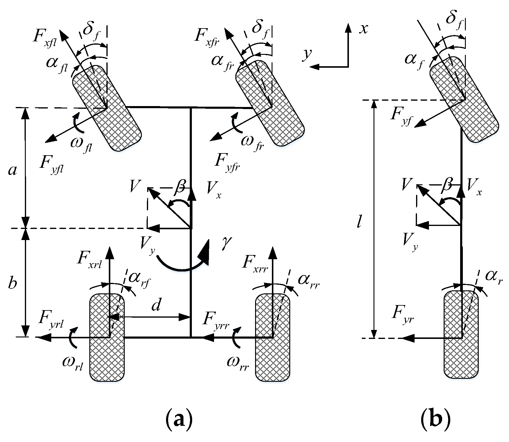
2.1. Vehicle Dynamics Model
2.2. Tire Model
2.3. Hub Motor Model
2.4. Driver Model
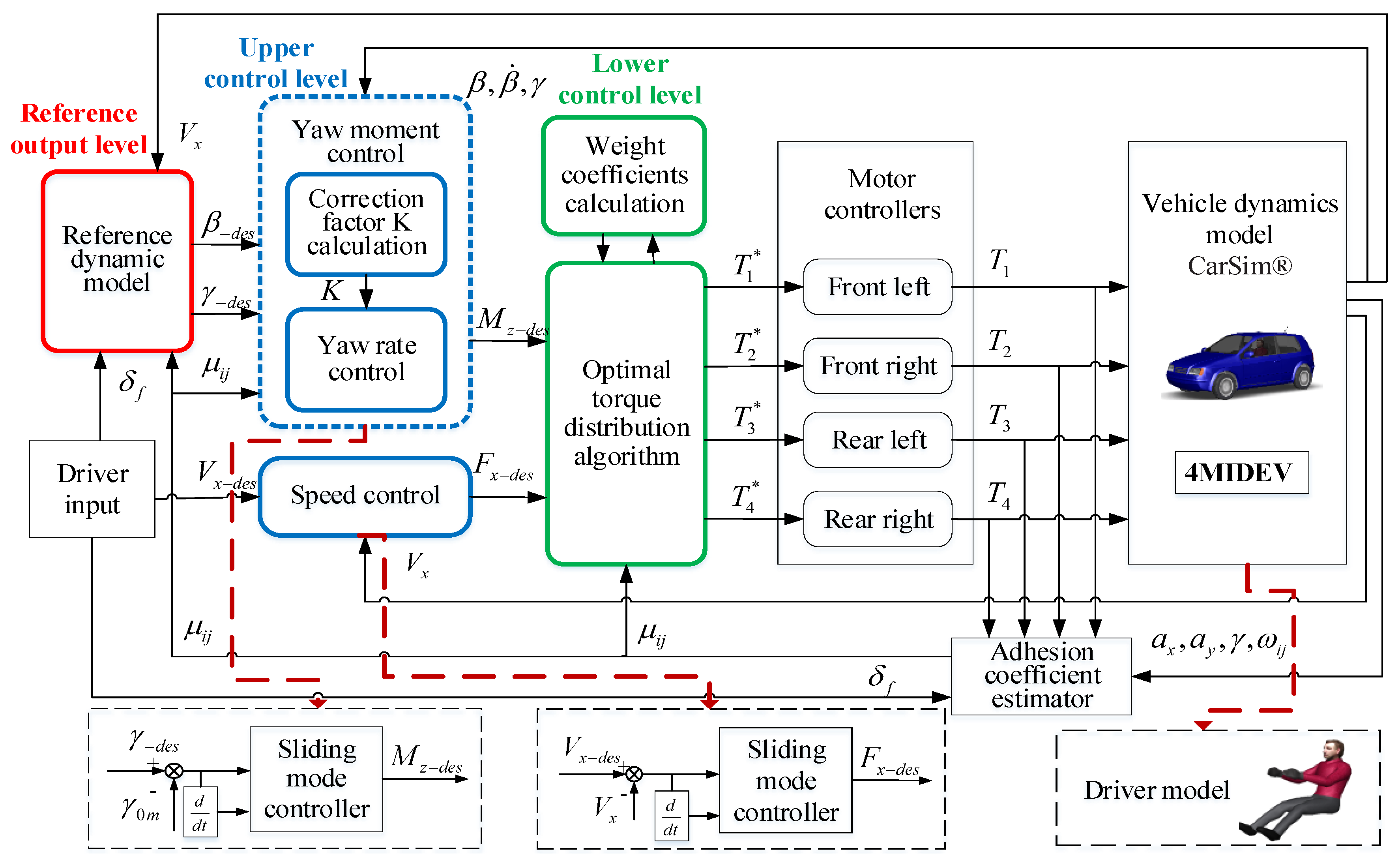
3. Design of Hierarchical Steering Stability Control Strategy for the 4MIDEV
3.1. Reference Output Level
3.2. Upper Control Level
3.2.1. Speed Control
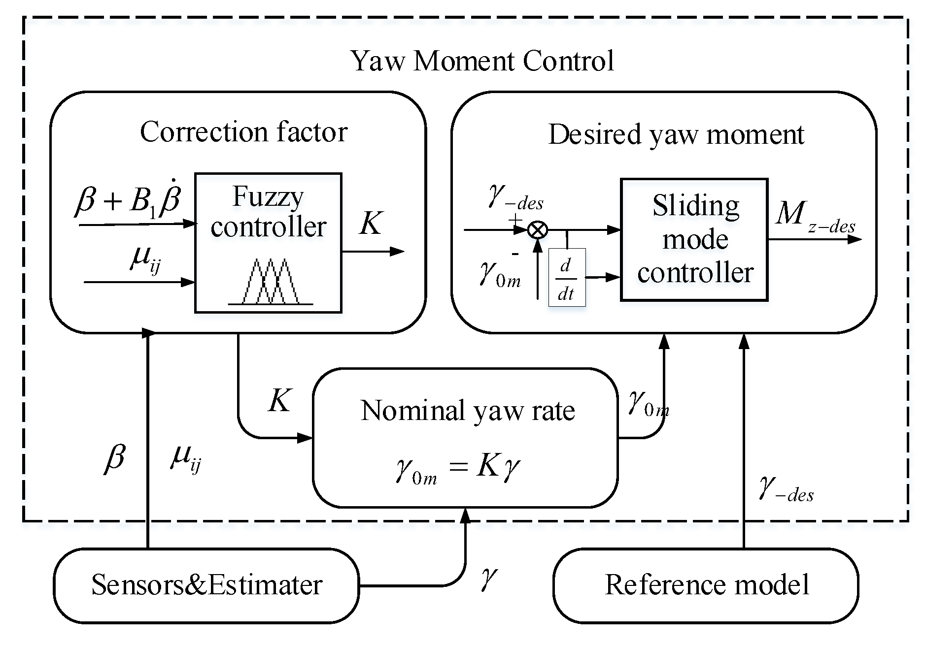
3.2.2. Yaw Moment Control
3.3. Lower Control Level
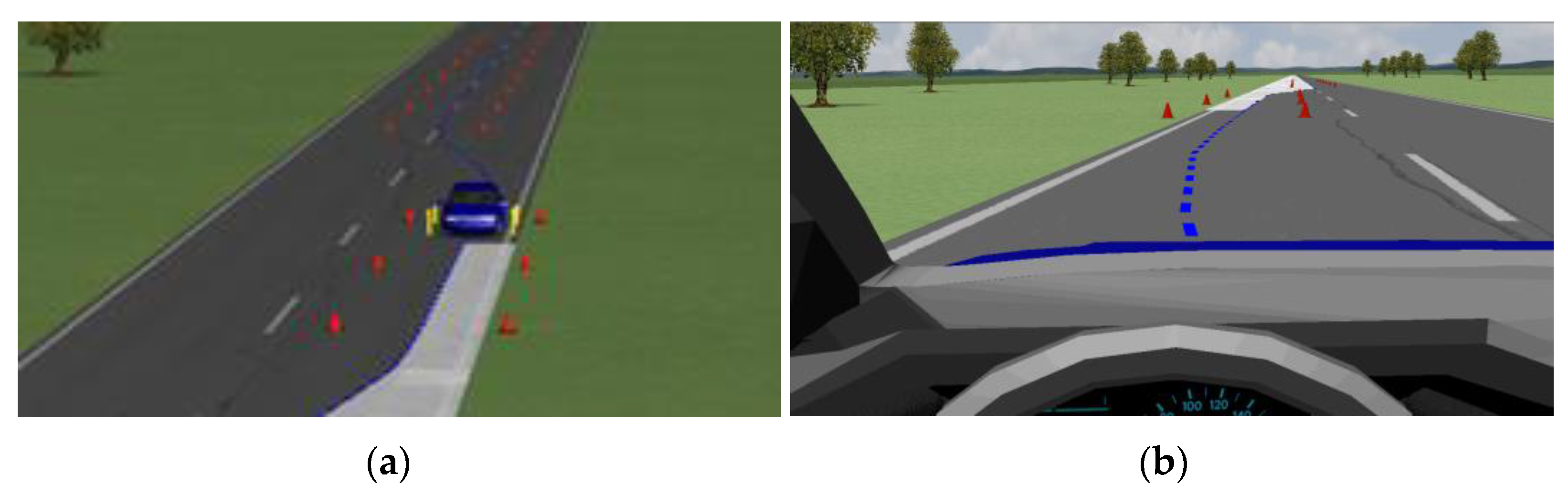
4. Simulation Test and Analysis
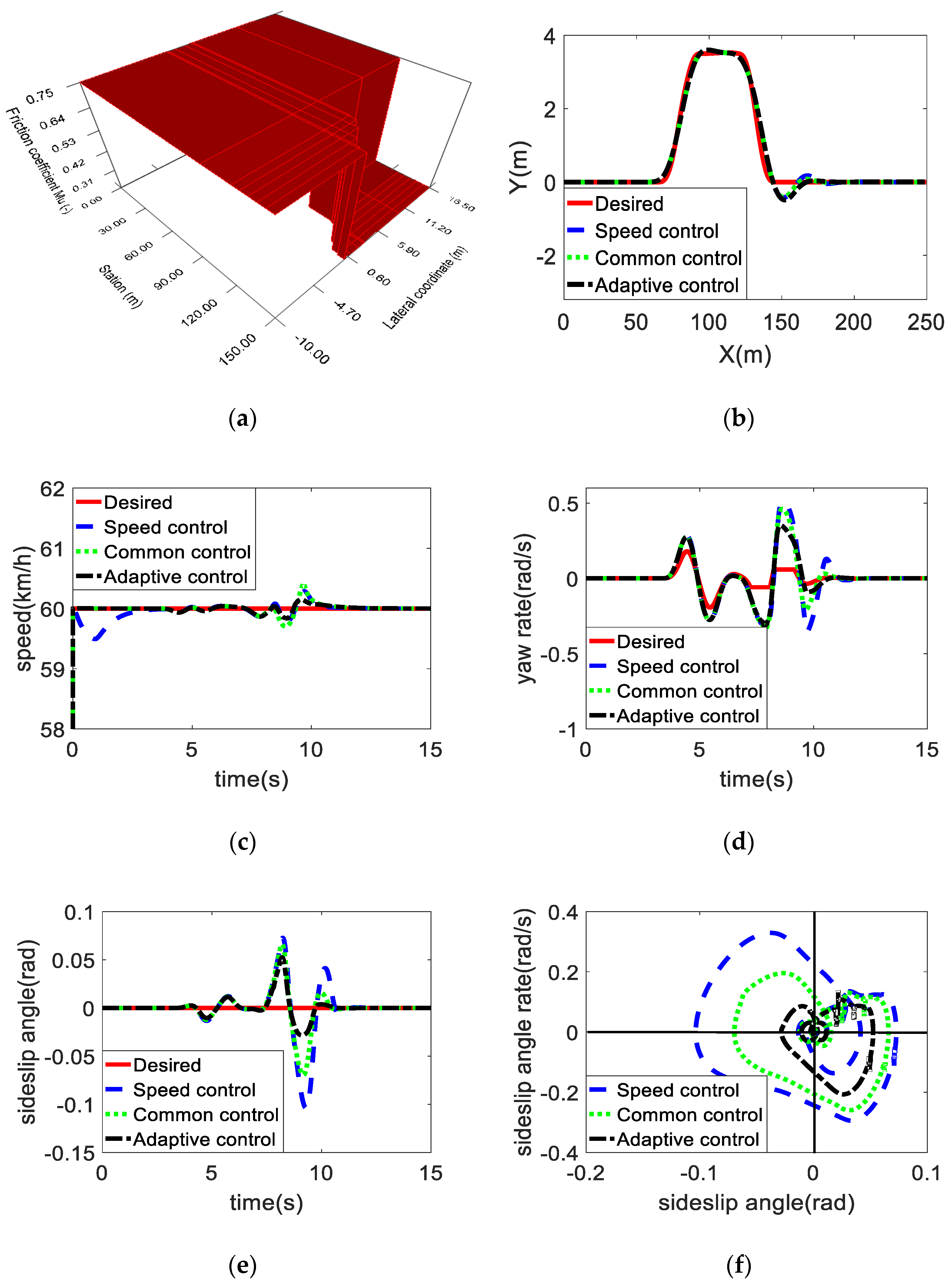
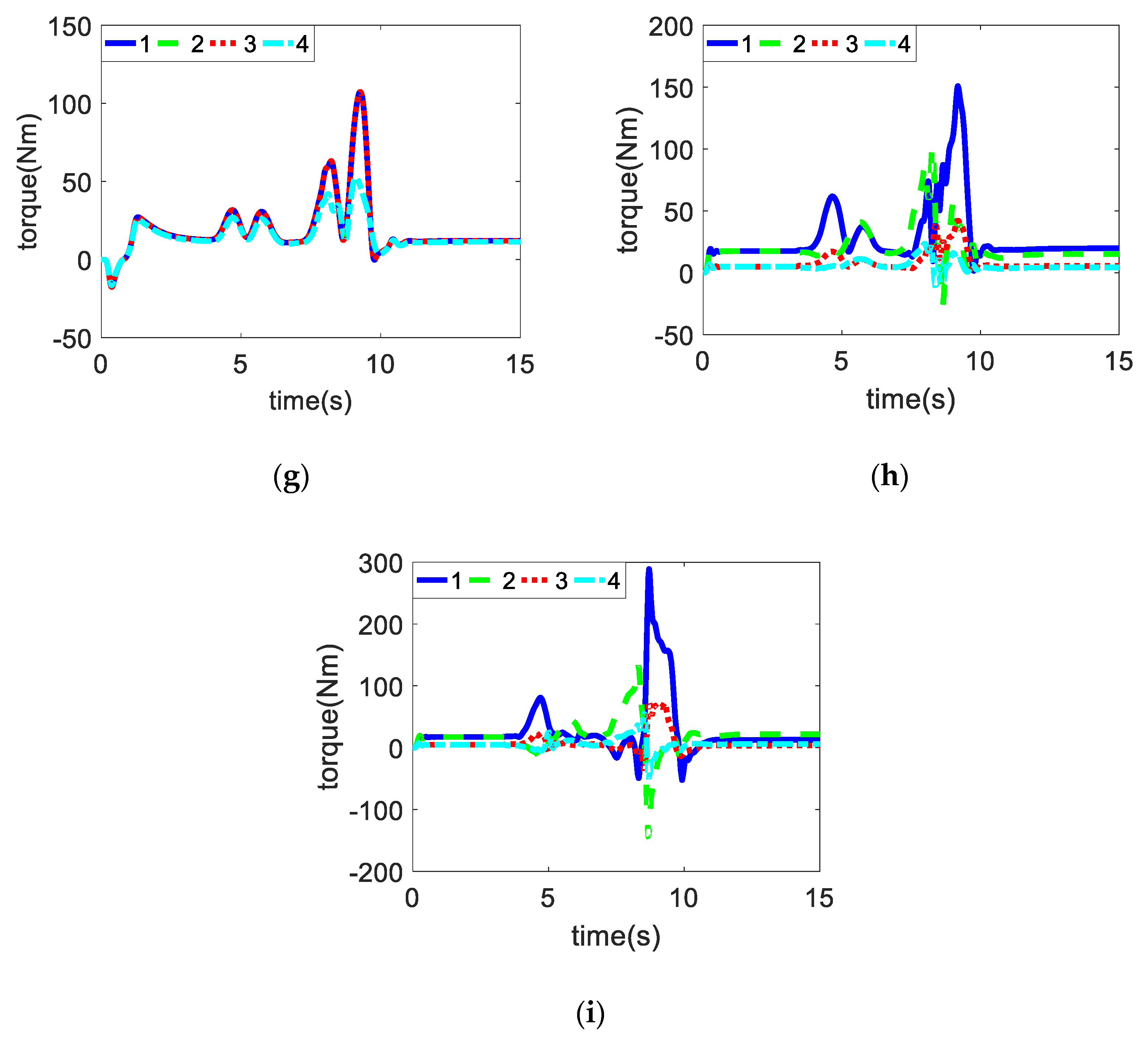
4.1. μ-Split Road
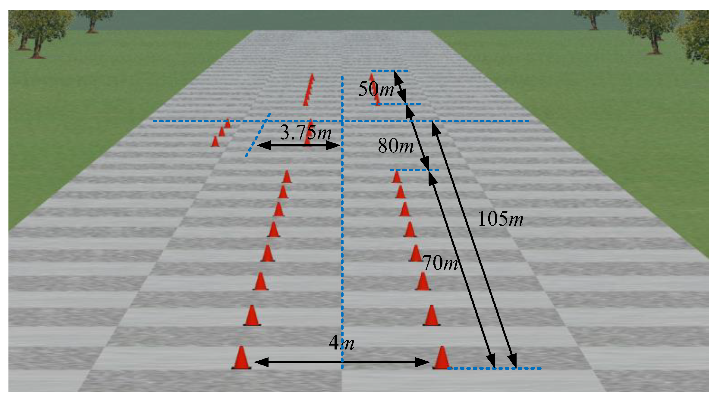
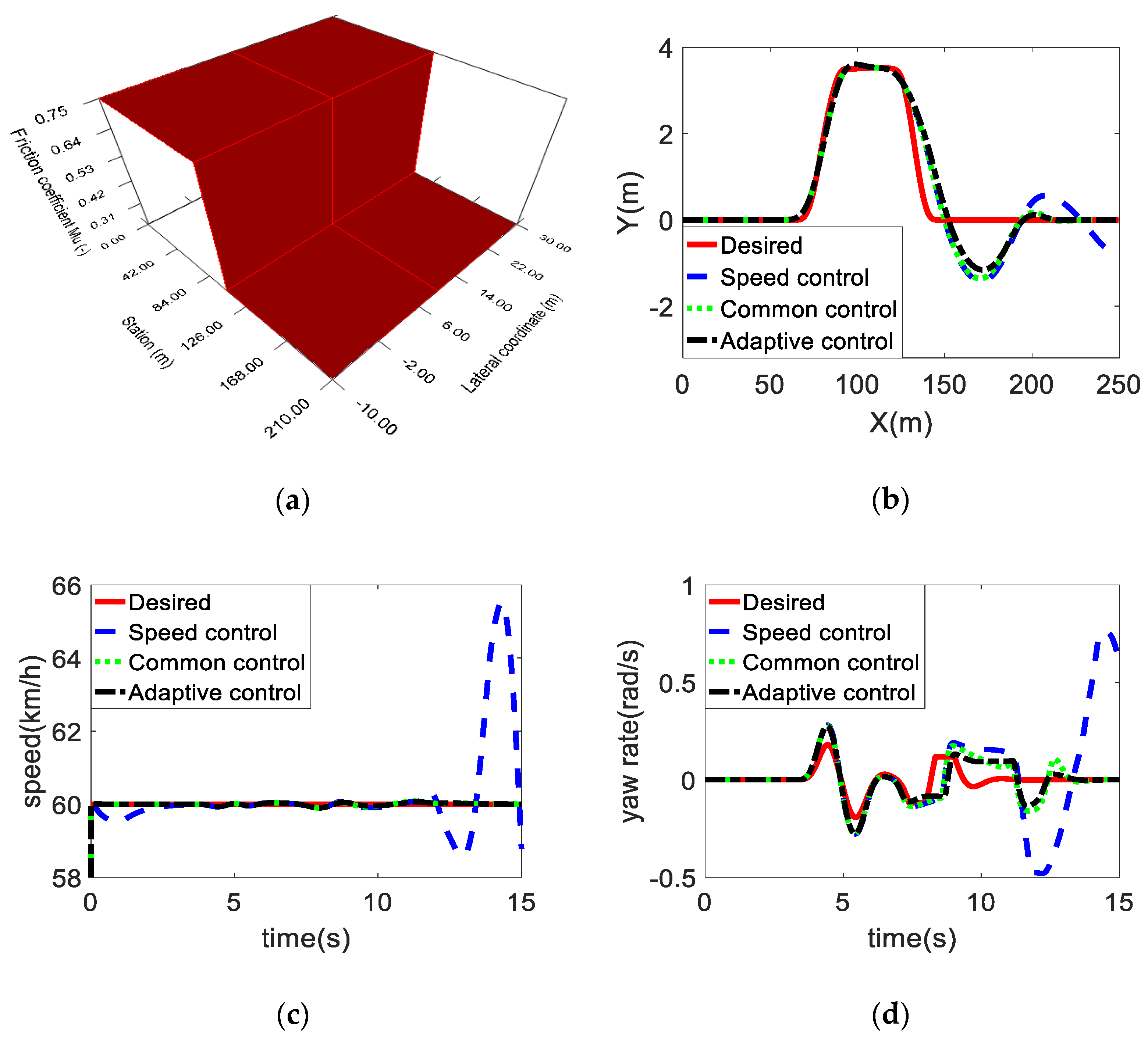
4.2. Joint Road
5. Conclusions
Author Contributions
Funding
Conflicts of Interest
References
- Zhang, X.D.; Göhlich, D. Integrated traction control strategy for distributed drive electric vehicles with improvement of economy and longitudinal driving stability. Energies 2017, 10, 126. [Google Scholar] [CrossRef]
- Liu, M.C.; Gu, F.H.; Zhang, Y.Z. Ride comfort optimization of in-wheel-motor electric vehicles with in-wheel vibration absorbers. Energies 2017, 10, 1647. [Google Scholar] [CrossRef]
- Fallah, S.; Khajepour, A.; Fidan, B.; Chen, S.K.; Litkouhi, B. Vehicle optimal torque vectoring using state-derivative feedback and linear matrix inequality. IEEE Trans. Veh. Technol. 2013, 62, 1540–1552. [Google Scholar] [CrossRef]
- Shuai, Z.B.; Zhang, H.; Wang, J.M.; Li, J.Q.; Ouyang, M.G. Combined AFS and DYC control of four-wheel-independent-drive electric vehicles over CAN network with time-varying delays. IEEE Trans. Veh. Technol. 2014, 63, 591–602. [Google Scholar] [CrossRef]
- Chen, Y.; Wang, J.M. Design and evaluation on electric differentials for overactuated electric ground vehicles with four independent in-wheel motors. IEEE Trans. Veh. Technol. 2012, 61, 1534–1542. [Google Scholar] [CrossRef]
- Kim, D.H.; Kim, C.J.; Kim, S.H.; Choi, J.Y.; Han, C.S. Development of adaptive direct yaw-moment control method for electric vehicle based on identification of yaw-rate model. In Proceedings of the 2011 IEEE Intelligent Vehicles Symposium (IV), Baden-Baden, Germany, 5–9 June 2011; pp. 1098–1103. [Google Scholar]
- Chen, J.; Yu, J.Z.; Zhang, K.X.; Ma, Y. Control of regenerative braking systems for four-wheel-independently-actuated electric vehicles. Mechatronics 2018, 50, 394–401. [Google Scholar] [CrossRef]
- Wang, Z.P.; Wang, Y.C.; Zhang, L.; Liu, M.C. Vehicle stability enhancement through hierarchical control for a four-wheel-independently-actuated electric vehicle. Energies 2017, 10, 947. [Google Scholar] [CrossRef]
- Ding, S.; Liu, L.; Zheng, W.X. Sliding mode direct yaw-moment control design for in-wheel electric vehicles. IEEE Trans. Ind. Electron. 2017, 64, 6752–6762. [Google Scholar] [CrossRef]
- Ren, B.T.; Chen, H.; Zhao, H.Y.; Yuan, L. MPC-based yaw stability control in in-wheel-motored EV via active front steering and motor torque distribution. Mechatronics 2016, 38, 103–114. [Google Scholar] [CrossRef]
- Alipour, H.; Sabahi, M.; Bannae Sharifian, M.B. Lateral stabilization of a four wheel independent drive electric vehicle on slippery roads. Mechatronics 2015, 30, 275–285. [Google Scholar] [CrossRef]
- Zhang, X.Z.; Wei, K.X.; Yuan, X.F.; Tang, Y.Q. Optimum torque distribution for stability improvement of four-wheel distributed driven electric vehicle using coordinated control. J. Comput. Nonlinear Dyn. 2016, 11. [Google Scholar] [CrossRef]
- Tahami, F.; Kazemi, R.; Farhanghi, S. A novel driver assist stability system for all-wheel-drive electric vehicles. IEEE Trans. Veh. Technol. 2003, 52, 683–692. [Google Scholar] [CrossRef]
- Lin, C.; Xu, Z.F. Wheel Torque Distribution of four-wheel-drive electric vehicles based on multi-objective optimization. Energies 2015, 8, 3815–3831. [Google Scholar] [CrossRef]
- Zou, G.C.; Luo, Y.G.; Lian, X.M.; Li, K.Q. A research of DYC for independent 4WD EV based on control target dynamic regulated. In Proceedings of the 2007 IEEE International Conference on Vehicular Electronics and Safety, Beijing, China, 13–15 December 2008; pp. 1–7. [Google Scholar]
- Tahami, F.; Farhangi, S.; Kazemi, R. A fuzzy logic direct yaw-moment control system for all-wheel-drive electric vehicles. Veh. Syst. Dyn. 2004, 41, 203–221. [Google Scholar] [CrossRef]
- Zhai, L.; Sun, T.M.; Wang, J. Electronic stability control based on motor driving and braking torque distribution for a four in-wheel motor drive electric vehicle. IEEE Trans. Veh. Technol. 2016, 65, 4726–4739. [Google Scholar] [CrossRef]
- De Novellis, L.; Sorniotti, A.; Gruber, P.; Orus, J.; Rodriguez Fortun, J.-M.; Theunissen, J.; De Smet, J. Direct yaw moment control actuated through electric drivetrains and friction brakes: Theoretical design and experimental assessment. Mechatronics 2015, 26, 1–15. [Google Scholar] [CrossRef]
- Jin, X.J.; Yin, G.D.; Chen, N. Gain-scheduled robust control for lateral stability of four-wheel-independent-drive electric vehicles via linear parameter-varying technique. Mechatronics 2015, 30, 286–296. [Google Scholar] [CrossRef]
- Park, J.; Park, Y. Optimal input design for fault identification of overactuated electric ground vehicles. IEEE Trans. Veh. Technol. 2016, 65, 1912–1923. [Google Scholar] [CrossRef]
- Zhai, L.; Hou, R.F.; Sun, T.M.; Kavuma, S. Continuous steering stability control based on an energy-saving torque distribution algorithm for a four in-wheel-motor independent-drive electric vehicle. Energies 2018, 11, 350. [Google Scholar] [CrossRef]
- Li, B.; Goodarzi, A.; Khajepour, A.; Chen, S.K.; Litkouhi, B. An optimal torque distribution control strategy for four-independent wheel drive electric vehicles. Veh. Syst. Dyn. 2015, 53, 1172–1189. [Google Scholar] [CrossRef]
- Bakker, E.; Pacejka, H.B.; Lidne, L. A New Tire Model with an Application in Vehicle Dynamics Studies. J. Passeng. Car. 1989, 98, 101–113. [Google Scholar]
- Li, S.Y.; Min, Y.J.; Wang, L.M.; An, L.H. Establishment and Simulation Analysis of Tire Dynamic Model. J. Nanjing Inst. Technol. (Nat. Sci. Ed.) 2009, 7, 34–38. [Google Scholar]
- Guo, K.H.; Pan, F.; Ma, F.J. Preview optimized artificial neural network driver model. Chin. J. Mech. Eng. 2003, 39, 26–28. [Google Scholar] [CrossRef]
- Song, P.; Tomizuka, M.; Zong, C.F. A novel integrated chassis controller for full drive-by-wire vehicles. Veh. Syst. Dyn. 2015, 53, 215–236. [Google Scholar] [CrossRef]
- Shimada, K.; Shibahata, Y. Comparison of Three Active Chassis Control Methods for Stabilizing Yaw Moments. J. Passeng. Car. 1994, 103, 1178–1187. [Google Scholar]
- Inagaki, S.; Kushiro, I.; Yamamoto, M. Analysis on vehicle stability in critical cornering using phase-plane method. In Proceedings of the International symposium on advanced vehicle control, Tsukuba, Japan, 24–28 October 2014. [Google Scholar]
- Mokhiamar, O.; Abe, M. Simultaneous optimal distribution of lateral and longitudinal tire forces for the model following control. J. Dyn. Syst. Meas. Control 2004, 126, 753–763. [Google Scholar] [CrossRef]
- Harkegard, O. Efficient active set algorithms for solving constrained least squares problems in aircraft control allocation. In Proceedings of the 41st IEEE Conference on Decision and Control, Las Vegas, NV, USA, 10–13 December 2002; pp. 1295–1300. [Google Scholar]
- Zhang, H.; Li, X.S.; Shi, S.M.; Liu, H.F.; Guan, R.; Liu, L. Phase Plane analysis for vehicle handling and stability. Int. J. Comput. Intell. Syst. 2011, 4, 1179–1186. [Google Scholar] [CrossRef]


| K | ||||||||
|---|---|---|---|---|---|---|---|---|
| NB | NM | NS | Z | PS | PM | PB | ||
| NB | PB | PB | PB | PM | PB | PB | PB | |
| NM | PB | PB | PM | PM | PM | PB | PB | |
| NS | PM | PM | PS | PS | PS | PM | PM | |
| Z | NM | NS | NS | Z | PS | PS | PM | |
| PS | NM | NM | NM | NS | NS | NS | NM | |
| PM | NB | NB | NM | NM | NM | NB | NB | |
| PB | NB | NB | NB | NM | NB | NB | NB | |
| Symbol | Quantity | Value |
|---|---|---|
| m | vehicle mass | 1411 kg |
| Iz | moment of inertia about the yaw axis | 2031.4 kg m3 |
| hg | height of the center of mass | 0.54 m |
| b | length from the center of gravity (CG) to the rear wheel axis | 1.56 m |
| a | length from the CG to the front wheel axis | 1.04 m |
| r | tire radius | 0.3 m |
| d | tread width | 1.48 m |
| Pm | maximum power | 28 kW |
| Tm | maximum torque | 340 Nm |
| nm | maximum speed | 1200 rpm |
| Pe | rated power | 14 kW |
| Te | rated torque | 170 Nm |
| ne | rated speed | 800 rpm |
© 2018 by the authors. Licensee MDPI, Basel, Switzerland. This article is an open access article distributed under the terms and conditions of the Creative Commons Attribution (CC BY) license (http://creativecommons.org/licenses/by/4.0/).
Share and Cite
Hou, R.; Zhai, L.; Sun, T. Steering Stability Control for a Four Hub-Motor Independent-Drive Electric Vehicle with Varying Adhesion Coefficient. Energies 2018, 11, 2438. https://doi.org/10.3390/en11092438
Hou R, Zhai L, Sun T. Steering Stability Control for a Four Hub-Motor Independent-Drive Electric Vehicle with Varying Adhesion Coefficient. Energies. 2018; 11(9):2438. https://doi.org/10.3390/en11092438
Chicago/Turabian StyleHou, Rufei, Li Zhai, and Tianmin Sun. 2018. "Steering Stability Control for a Four Hub-Motor Independent-Drive Electric Vehicle with Varying Adhesion Coefficient" Energies 11, no. 9: 2438. https://doi.org/10.3390/en11092438
APA StyleHou, R., Zhai, L., & Sun, T. (2018). Steering Stability Control for a Four Hub-Motor Independent-Drive Electric Vehicle with Varying Adhesion Coefficient. Energies, 11(9), 2438. https://doi.org/10.3390/en11092438