Article

Investigation on the Application of NMR to Spontaneous Imbibition Recovery of Tight Sandstones: An Experimental Study

1
State Key Laboratory of Petroleum Resources and Prospecting in China University of Petroleum, Beijing 102249, China
2
Ministry of Education Key Laboratory of Petroleum Engineering in China University of Petroleum, Beijing 102249, China
3
Hubei Subsurface Multi-Scale Imaging Key Laboratory, Institute of Geophysics and Geomatics, China University of Geosciences, Wuhan 430074, China
*
Authors to whom correspondence should be addressed.
Energies 2018, 11(9), 2359; https://doi.org/10.3390/en11092359
Submission received: 1 August 2018 / Revised: 1 September 2018 / Accepted: 5 September 2018 / Published: 6 September 2018
(This article belongs to the Special Issue Flow and Transport Properties of Unconventional Reservoirs 2018)

Abstract

:
In this paper, the nuclear magnetic resonance (NMR) technique is applied to exploring the spontaneous imbibition mechanism in tight sandstones under all face open (AFO) boundary conditions, which will benefit a better understanding of spontaneous imbibition during the development of oil & gas in tight formations. The advantages of nuclear magnetic resonance imaging (NMRI) and NMR T2 are used to define the distribution of remaining oil, evaluate the effect of micro structures on imbibition and predict imbibition recovery. NMR T2 results show that pore size distributions around two peaks are not only the main oil distributions under saturated condition but also fall within the main imbibition distributions range. Spontaneous imbibition mainly occurs in the first 6 h and then slows down and even ceases. The oil signals in tiny pores stabilize during the early stage of imbibition while the oil signal in large pores keeps fluctuating during the late stage of imbibition. NMRI results demonstrate that spontaneous imbibition is a replacement process starting slowly from the boundaries to the center under AFO and ending with oil-water mixing. Furthermore, the wetting phase can invade the whole core in the first 6 h, which is identical with the main period of imbibition occurring according to NMR T2 results. Factors influencing the history of oil distribution and saturation differ at different periods, while it is dominated by capillary imbibition at the early stage and allocated by diffusion at later time. Two imbibition recovery curves calculated by NMRI and NMR T2 are basically consistent, while there still exists some deviations between them as a result of the resolutions of NMRI and NMR T2. In addition, the heterogeneity of pore size distributions in the two samples aggravates this discrepancy. The work in this paper should prove of great help to better understand the process of the spontaneous imbibition, not only at the macroscopic level but also at the microscopic level, which is significant for oil/gas recovery in tight formations.

1. Introduction

Tight oil reservoirs show typical low porosity and ultralow permeability characteristics, caused by a wide pore size distribution and complex pore throat structures [1,2,3]. Large volumes of slick water during multistage hydraulic fracturing are pumped into the tight formation to improve petrophysical properties by creating complex fracture networks [4,5]. Therefore, the spontaneous imbibition mechanism in tight sandstones is a key issue that needs to be focused upon to prevent channeling in the development of tight oil reservoirs. Hence, oil recovery by spontaneous imbibition is of special importance in tight formations, particularly when the formation is characterized by developed fractures [6,7]. For decades, researchers have carried out a lot of research on imbibition and obtained important conclusions [8,9,10]. The characterization of the imbibition process, especially in tight formations, has become a research hot topic. Many authors have focused on evaluating the imbibition recovery based on conventional experiments, while few of them have examined the imbibition recovery and residual oil distributions at microscopic level [11,12,13,14,15]. Indeed, acquiring a better understanding of spontaneous imbibition in tight oil reservoirs can be tricky because of a wide pore size distribution with a significant portion of it being nanoscale porosity [3]. Furthermore, an accurate measurement of oil imbibed from tight samples is crucial for calculating the oil recovery of spontaneous imbibition. Traditional measurement methods such as the volume method and the mass method, are not suitable for imbibition of tight oil [16,17,18]. Therefore, a new method for characterizing spontaneous imbibition is desperately needed. NMR has become a common experimental method in light of its fast, visual and non-destructive properties [19,20,21,22]. On the one hand, NMRI can obtain images of the residual oil distribution and imbibition front at relatively large scales [23,24]. On the other hand, NMR T2 can reflect quantitatively the residual oil distributions at microscopic level [25,26]. Therefore, not only the imbibition front can be observed, but also the fluids change at pore scale during spontaneous imbibition can be obtained [27,28].
In this paper, spontaneous imbibition experiments and NMR tests are performed in tight sandstone samples. This study aims to explore the potential of the NMR technique in characterizing the microscopic imbibition mechanism in tight oil reservoirs. First of all, The changing characteristics of the wetting and non-wetting phase at the microscopic level during imbibition are described using NMR T2; Secondly, imbibition front advancing characteristics are observed by NMRI; lastly, the applicability of two methods for calculating the imbibition recovery is evaluated and the reasons for the deviations of imbibition recovery based on the two methods are respectively discussed.

2. Methodology

Imbibition recovery is an important parameter when evaluating imbibition effect. During imbibition, oil is always adhered to the core surface and not easy to separate from core plugs. Moreover, the oil content in tight sandstone core is low and the volume of oil that can be imbibed from the core is less, which is difficult to measure. As a result, traditional methods of predicting imbibition recovery present defects. Therefore, simple and efficient methods of predicting imbibition recovery in tight sandstones are desperately needed. Herein, two methods for predicting imbibition recovery are recommended based on NMR T2 distributions and NMR 2D-images, which is respectively called the NMR T2 method and the NMRI method.

2.1. NMR T2

Under the action of radio frequency (RF) pulses hydrogen nuclei not only change in phase, but also absorb energy to transition to higher energy states. After the RF excitation stops, the phase and energy of hydrogen nuclei are restored to the original state. This process is called relaxation. There are two relaxation times: T1 (longitudinal relaxation time) and T2 (transverse relaxation time). Although, T2 contains the same information as T1 (T1 = kT2, k is constant), but it has more collected points than T1. Moreover, the time for obtaining T2 is much shorter [29,30]. Therefore, T2 is usually choosen for core analysis. The expression for T2 can be expressed as follows [19]:
1 T 2 = ( 1 T 2 ) S + ( 1 T 2 ) D + ( 1 T 2 ) B
where ( 1 T 2 ) S is the relaxation contribution from the surface of the rock particles (1/ms), ( 1 T 2 ) D is the relaxation contribution from diffusion in magnetic gradients (1/ms), ( 1 T 2 ) B is the relaxation contribution from bulk (1/ms). Equation (1) can also be described as follows:
1 T 2 = ρ 2 ( S V ) + D ( γ G T E ) 2 12 + 1 T 2 B
Since the value of T2B is always 2~3 s, which is much larger than T2. 1 T 2 B in Equation (2), it can be ignored. G is the magnetic gradient (gauss/cm), whose value is 0 in uniform magnetic field. Therefore, D ( γ G T E ) 2 12 in Equation (2) can also be ignored. Hence, Equation (1) can be converted to Equation (3):
1 T 2 = ρ 2 ( F S r )
where FS is the shape factor for irregular balls, for example, FS equals 3 in a spherical model and equals 2 in a column model. r is the pore and throat radius (um), ρ 2 is the transverse relaxation strength (constant). Therefore, a relationship between T2 and the pore radius can be further built in Equation (4):
r = C T 2
where C = 1 F S ρ 2 , μm/ms C is a constant since FS and ρ2 are constant. Thus, there is a one to one relationship existing between T2 and r. The coefficient factor C in Equation (4) can be obtained by contrasting the T2 distribution and the pore throat size by PCP [31]. Consequently, the larger pores have a longer relaxation time. And the larger the pore volume of the corresponding pore, the larger the area of pore radius.
With the NMR T2 method, the remaining oil percentage can be obtained by dividing the sum of the signal amplitudes at a measurement time by that at the initial time. The imbibition recovery can be calculated using the remaining oil percentage and the specific expression is shown in Equation (5):
R N M R = ( 1 A i A 0 ) 100 %
where RNMR is the imbibition recovery calculated by Equation (5), %, Ai is the acreage enclosed by T2 curves of core after imbibition and on the X-axis, A0 is the acreage enclosed by T2 curves of core under saturation conditions and on the X-axis.

2.2. NMRI

There are three factors contributing to the signal in the process of general NMRI, including the longitudinal relaxation time, the transversal relaxation time and the hydrogen proton density [19]. The signal amplitude in NMRI can be expressed as follows:
A = A O ρ ( 1 e T R / T 1 ) e T E / T 2
where A is the signal amplitude, AO is the original signal amplitude, ρ is the hydrogen proton density, TR is the repeat time, T1 is the longitudinal relaxation time, and TE is the echo time. As can be seen from Equation (6), we can highlight the effect of one factor and restrain the effects of two other factors by adjusting the imaging parameters. In this paper, a larger TR and a smaller
. TE were set, weighing the impact of proton density and reducing the impact of T1 and T2 on the image, which is also called the proton density-weighted imaging method. Consequently, Equation (6) can be converted into Equation (7):
A = A O ρ
As can be seen from Equation (7), the signal amplitude is determined only by ρ. The stronger the signal intensity, the larger the proton density and the more the oil content. Therefore, images of oil distributions can be obtained by Equation (7), which is called the NMR proton density-weighted imaging method. The specific process of obtaining NMRI images is described below: select a slice of the sample parallel to the gradient magnetic field in the Z-axis direction. At the same time, the Y-axis of a pixel can be determined by phase encoding and the X-axis determined by rate encoding. 2D-images can be reconstructed based on signal intensity and the information above, which reflects oil distributions in a core section.
With the NMRI method, the remaining oil percentage can be obtained by dividing the mean of pixels at a measurement time by the mean of pixels at the initial time. The imbibition recovery can also be calculated using the remaining oil percentage and the specific expression is shown in Equations (8) and (9):
R N M R I = ( 1 P 1 ¯ P o ¯ ) × 100 %
P ¯ = 1 5500 P n 5500
where R N M R I is the imbibition recovery calculated by Equation (8),%, P i ¯ is the pixel mean of 5500 voxels at a certain imbibition moment, P o ¯ is the pixel mean at the initial time, Pn is the pixel value of one pixel, P 1 ¯ and P o ¯ can be calculated by Equation (9). 5500 pixels are randomly selected from the NMR 2D-images.

3. Experimental Materials

3.1. Samples

Two cylindrical outcrop tight samples were collected to perform spontaneous imbibition and NMR tests in this study. Petrophysical properties of two samples are shown in Table 1. The length and radius of core plugs were measured, and then helium porosity and nitrogen permeability tests were performed. Contact angle was measured by the contact angle measuring instrument JC2000D3. It should be noted that oil saturation in Table 1 represents the oil percentage of a blank core after being saturated by white oil-5 and the detailed calculation can be referred in Section 3.4.

3.2. Fluids

In order to eliminate the hydrogen signal of water, MnCl2 solution with the weight percentage of 40% is selected as the wetting phase by comparing the shield effect of various MnCl2 solutions with different concentrations. So as to avoid volatilization in the magnetic chamber, white oil-5 is used as the non-wetting phase instead of kerosene, which is characterized by a density of 0.82 g/cm3 and a viscosity of 3.5 mPa·s.

3.3. Experimental Instrument

A PANalytical diffractometer was used to acquire the relative mineral percentages, estimated by a semi-quantitative method. It was performed on powdered tight sandstone at room temperature under a relative humidity (RH) of 66 %.
NMR tests were performed on a MacroMR23-60H-I instrument (Suzhou Niumag Analytical Instrument Corporation, Suzhou, China) with a constant magnetic field strength of 0.55 T and a resonance frequency of 23.408 MHz. The measurement parameters are as follow: echo spacing, 0.12 ms; waiting time, 2500 ms; echo numbers, 6000; numbers of scans, 64. All experiments were conducted at room temperature under a relative humidity of 60%. The temperature of the magnetic chamber was 305.15 K.

3.4. Experimental Procedure

Firstly, core samples were dried at 378.15 K to a constant weight. Then the core samples were weighed and measured (both the length and the diameter). Secondly, two core samples were saturated by displacement until 8 pore volume white oil-5 are obtained at the end of the core holder. The weights of the saturated cores were recorded. The oil saturation (Table 1) of each core can be calculated using the dry weight, the wet weight and the volume of the sample. Thirdly, raw NMR data of oil-saturated cores were obtained. At last, the oil-saturated cores were immersed in MnCl2 solution to simulate spontaneous imbibition under AFO boundary conditions (Figure 1). Boundary conditions are complicated due to the existence of both co-current and counter-current imbibition, among which AFO condition is the most common one. The boundary condition AFO was chosen to further investigate in this study [32,33,34]. Six sets of NMR experiments were conducted at 3 h, 6 h, 19 h, 26 h, 60 h, and 180 h after being immersed into MnCl2 solution (The rate of spontaneous imbibition slow down with time in previous research, measurement intervals were small at the early stage of spontaneous imbibition and then measurement intervals were large at the later stage of spontaneous imbibition, so our NMR measurements were set at 3 h, 6 h, 19 h, 26 h, 60 h, and 180 h). Then, NMR T2 and NMR images for each set of the NMR experiment were obtained.

4. Results and Discussion

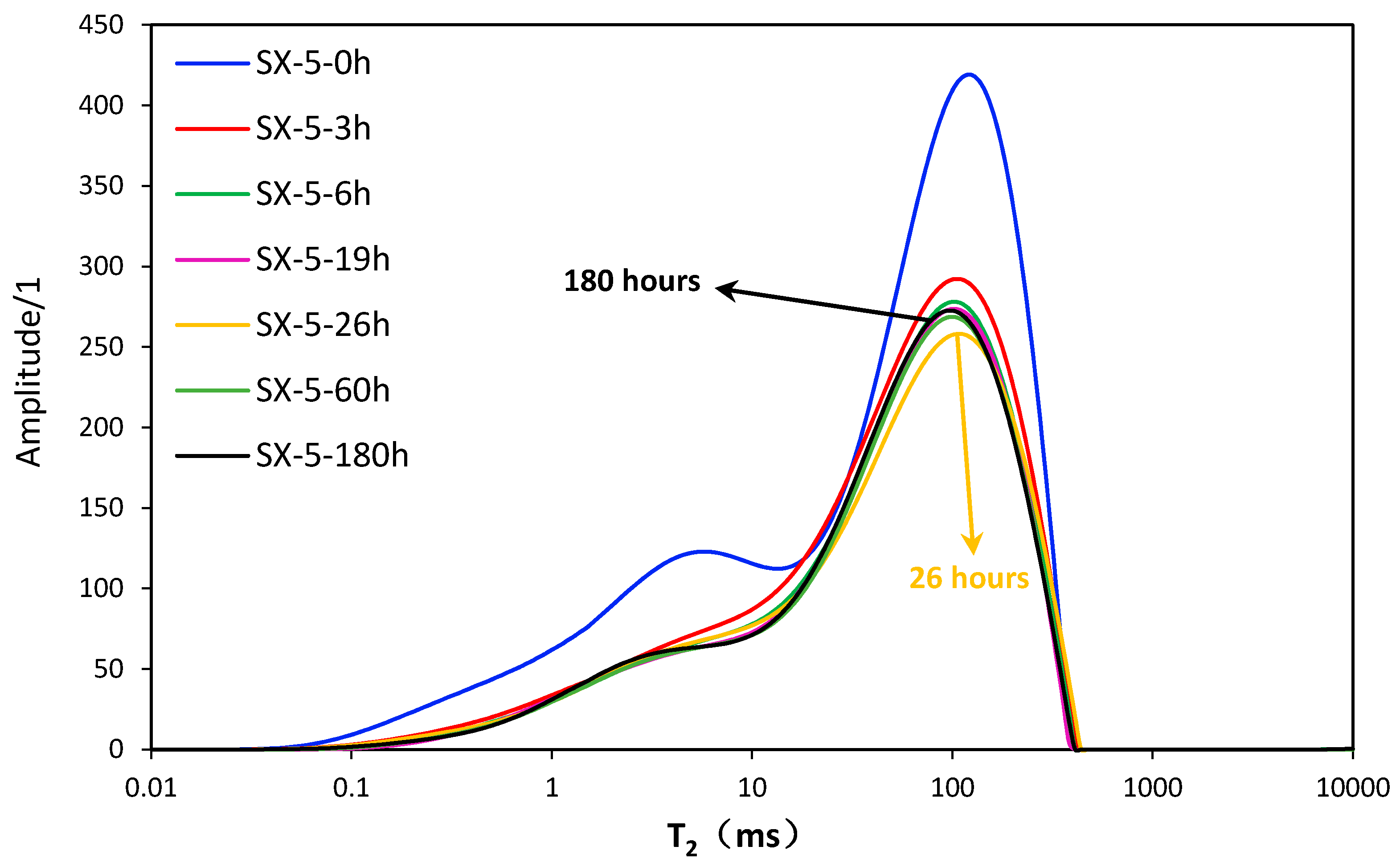
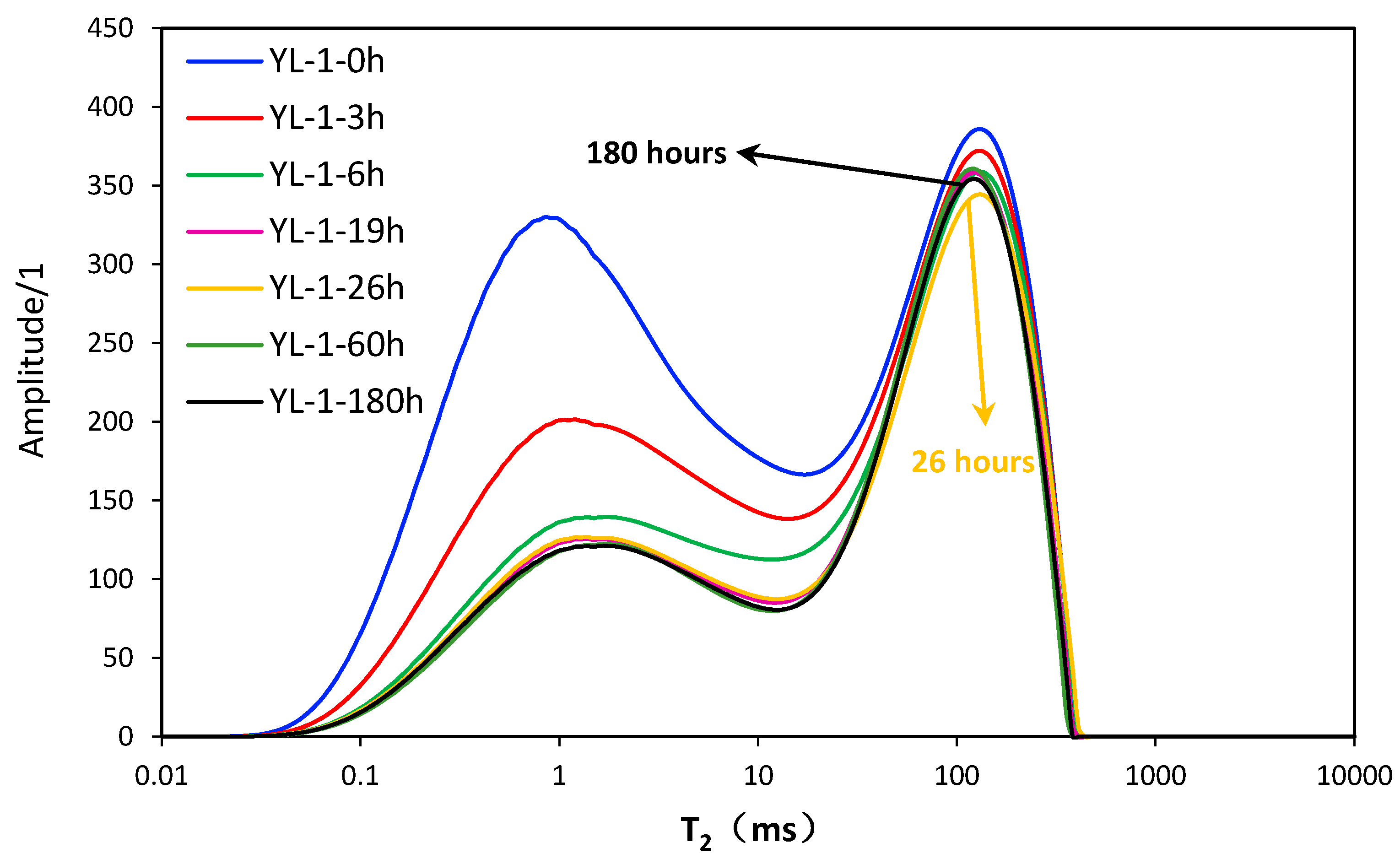
4.1. NMR T2 under Saturated Condition

The top curves in Figure 2 and Figure 3 show the T2 distributions of samples under saturation condition. Each T2 distribution curve shows two peaks with a higher right peak and a lower left peak. The larger the value of T2 is, the bigger the pore is. Pores ranging 10 ms–1000 ms and 0.1 ms–10 ms can be defined as large pores and tiny pores respectively, which is around right peak and left peak. The two peaks of SX-5 are located at about 5 ms and 100 ms whereas the two peaks of YL-1 are located at about 1 ms and 150 ms. The height of the left peak is obviously lower than that of the right one in SX-5, while the divergence is smaller inYL-1. The area enclosed by left peak is apparently smaller than that of the right peak for SX-5, while the relationship is opposite for YL-1. In conclusion, oil content in tiny pores is less than oil content in large pores for SX-5 and the relationship in YL-1 is just opposite. One possible reason for the difference is probably that YL-1 has more tiny pores than SX-5. The other probable reason is that YL-1 has a better connectivity. However, considering the high oil saturation of the two samples (Table 1). We attribute the difference to the first one.

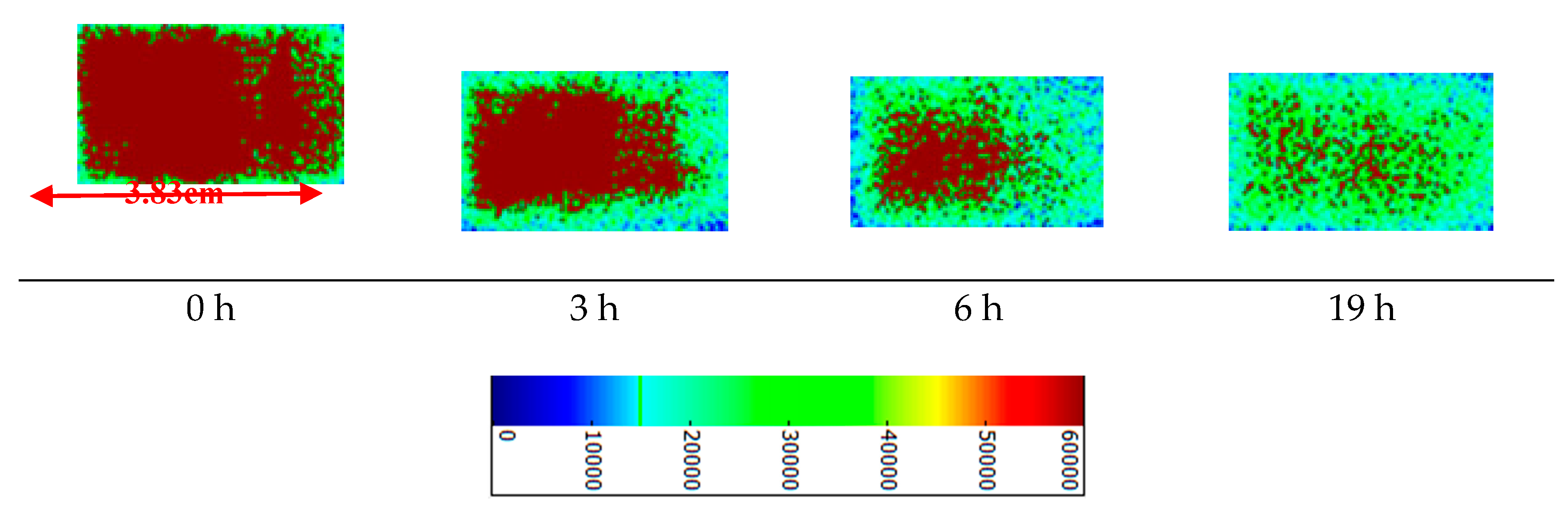
4.2. Remaining Oil Distributions after Imbibition

The other six curves from top to bottom in Figure 2 or Figure 3 represent the T2 distribution curves of the remaining oil in the core after imbibition for 3 h, 6 h, 19 h, 26 h, 60 h and 180 h, for simplicity, they are recorded as C3, C6, C19, C26, C60 and C180, respectively. When taking the overall process of imbibition of SX-5 into account, the left peak of C3 descends significantly and part of the left peak of C6 descends slightly. Left peaks of C6 and C19 almost coincide with each other. Then the left peak of C26 rises up and then the left peaks of C60 and C180 are almost identical. When it comes to the right peaks at different imbibition time, it can be seen that the right peaks of C19 and C6 almost coincide. The right peak of C26 falls down slightly and then the right peaks of C60 and C180 both rise up in an apparent manner. The change of T2 distributions of SX-5 indicates that the main imbibition time of tiny pores and large ones is relatively 0~3 h and 0~6 H. In contrast with SX-5, YL-1 shows a more obvious main imbibition pore size interval around the left peak. The left peak falls down continuously at early stage and then stays unchanged during the 19–26 h period, then slightly falls down at 60 h and again stays unchanged at 180 h. The right peak falls down slightly during the first 26 h, then rises up a little at 60 h and again falls down slightly at 180 h. However, the right peak of C180 is still lower than that of C60, but still higher than that of C26. As for the reasons why the time of experiment sets 26 h is fallen as the lowest curve and 180 h located in the middle in both Figure 2 and Figure 3, and the oil signal amplitude in pores, especially in large pores, fluctuates during the later period of imbibition process, the detailed explanation can be found in Section 4.3.
The changes of the two peaks of the two samples during the imbibition process are not synchronized, which indicates that the difference of imbibition between tiny pores and large pores is obvious. The left peaks of the two samples move right during imbibition which does not happen in the right peak, indicating that tiny pores exert a strong advantage in imbibition. At the early stage of imbibition process of two samples, oil in tiny pores is displaced by the wetting phase and oil in large pores is also discharged by counter-current imbibition under the AFO boundary condition. Therefore, the oil signal of tiny pores and large pores is weakened just as in the T2 results above. Tiny pores play a stronger role than large pores in imbibition at the early stage. Reasons for this are as follows: on the one hand, as the main driving force for imbibition, the capillary force of large pores is smaller than that of tiny pores. As a result, imbibition in large pores is slower than that in tiny pores. On the other hand, both oil originally stored in large pores and oil imbibed from tiny pores should be discharged from the large pores at the same time. Therefore, the oil signal in tiny pores decreases more quickly than in large pores at the beginning. Since tiny pores in SX-5 are less developed, the difference of imbibition intensity between tiny pores and large pores in SX-5 is little. Also, the above reasons as well as the existence of abundant tiny pores inYL-1 leads to a significantly main imbibition interval. As imbibition continues, the oil signal in tiny pores and maintains a slightly downward trend and even tends to remain unchanged while the oil signal in large pores fluctuates during the later stage.
At the same time, the common point of two samples is that tiny pores show a strong ability of imbibition. However, by comparing the two samples, we can find that there are some differences between them. The first one is that imbibition in tiny pores of YL-1 lasts longer than that of SX-5. The other is that large pores of SX-5 show a stronger ability of imbibition than those of YL-1. Since right peaks of SX-5 and YL-1 are located at 5 ms and 1ms when left ones are at 100 ms and 150 ms, tiny pores distributed in the left peak of YL-1 have a larger capillary force than those of SX-5 while the capillary force in large pores in the right peak shows the opposite result. Hence, tiny pores ofYL-1 show a stronger imbibition than those of SX-5 when large pores display the opposite result. Therefore, more oil is imbibed from tiny pores to large ones. It is thus not imbibed out of large pores. Consequently, oil is trapped in large pores, which leads to a slow fall of the right peak of T2 distribution. As can be seen from all the above statements, the pore size distribution has a great effect on imbibition. Pore size distribution can account for the two differences.

4.3. Imbibition Front

2D-images in Figure 4 and Figure 5 are reconstructed by employing the NMR proton density-weighted imaging method, which represent fluid distributions in the center section of cylindrical cores at different stages (0 h, 3 h, 6 h, 19 h) of imbibition. It is noted that NMR-2D images at 26 h, 60 h, and 180 h were left out because few changes happen after 26 h. The red area means that core is saturated 100% by oil and the blue region on the edge of the core is affected by a noise-signal ratio. The green color corresponds to the oil-water two phase region and the lighter green is related to areas with a larger water saturation. As can be seen from Figure 5, oil is evenly distributed throughout the overall section before imbibition. The oil signal around the border then weakens. Furthermore, the oil-water mixing zone approaches the center of 2D-image with imbibition carrying on taking place. Finally, the whole core is filled with oil-water two phase. The center of the 2D-image corresponds to a no-flow boundary, which is invaded by water at last. The core surface is directly contacted with the wetting phase under AFO boundary condition, which can be considered as the situation where the matrix is coming into contact with the fractures, in this paper. It can also be seen from Figure 4 and Figure 5 that although the resolution of NMRI 2D-image is low, the imbibition front advancing is relatively clear. Spontaneous imbibition is a replacement process starting slowly from the boundaries towards the center, in which a radial displacement is formed during counter-current imbibition under AFO boundary conditions.
The results demonstrate that the wetting phase can invade the whole core in 6 h. The change of fluid distribution is no longer obvious when time passes from 6 h to 19 h. As concluded in Section 4.2, NMR T2 curves of the remaining oil distributions after 6 h also change a little, which makes good agreement. The oil signal inYL-1 changes obviously from 0 h to 19 h and pure oil areas are sporadically distributed near the no-flow boundary until 19 h, which coincides with the changes of the left peak of YL-1 T2 curves. Therefore, the imbibition front advancing trend concluded from NMRI makes good accordance with NMR T2. According to the results of NMRI and NMR T2, continuous oil is cut off once water invades the whole core. The reason why the oil signal amplitude in pores, especially in large pores, fluctuates during the later period of the experiment is that diffusion plays a dominant role in the distribution change of discontinuous oil. Based on observations above, we concluded that the early imbibition time represents a period dominated by the capillary force, whereas the later period towards the end of the experiment is controlled by diffusion. During the later period of imbibition, the oil signal in large pores increases in an obvious manner and the oil signal in tiny pores fluctuates slightly or even stays unchanged. The oil in tiny pores invaded into larger pores under the process of diffusion and the oil is not discharged out timely, which causes an increase of the oil signal in large pores. It can be seen that the remaining oil is mainly distributed in the larger pores and cannot be fully imbibed by water.

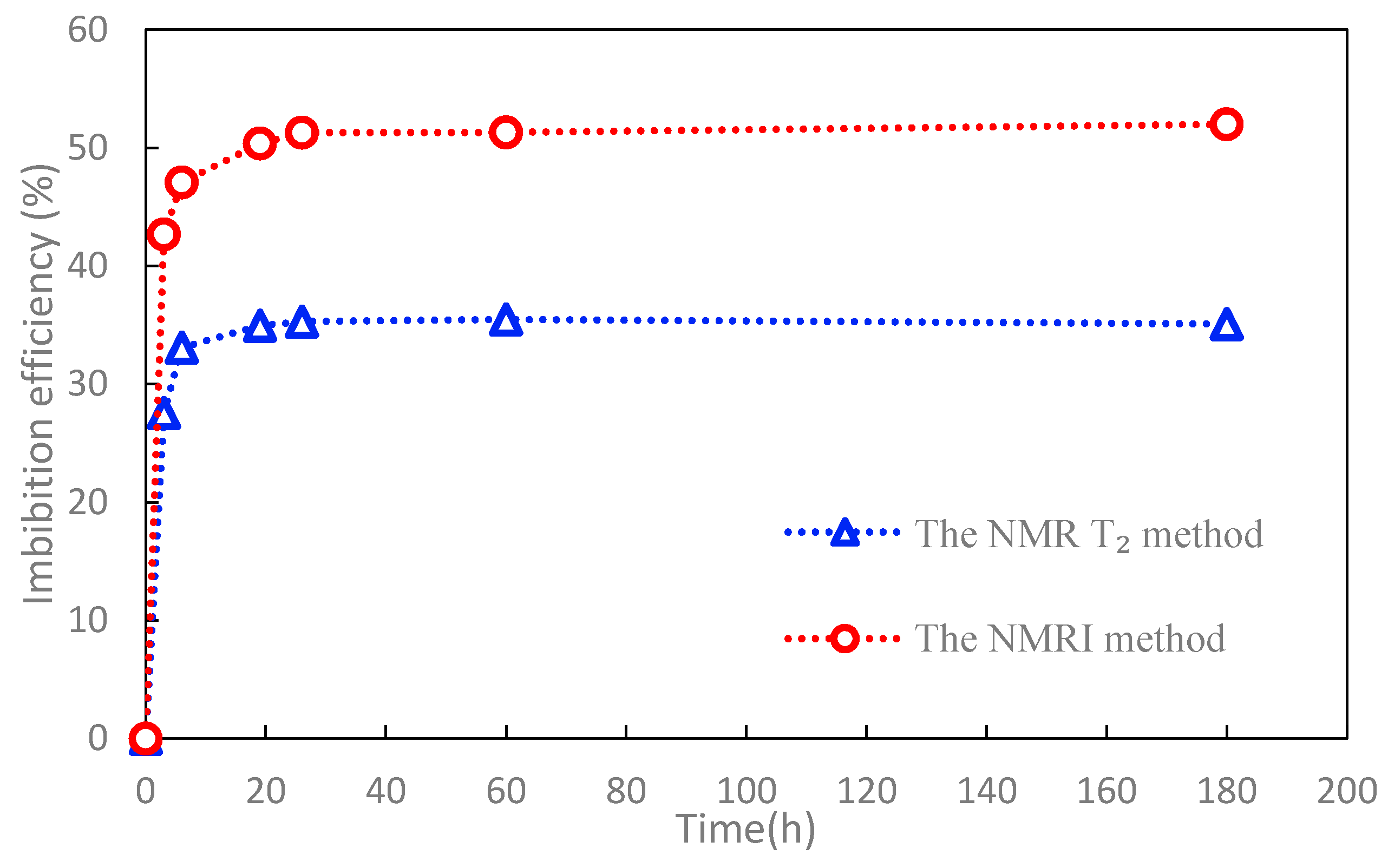
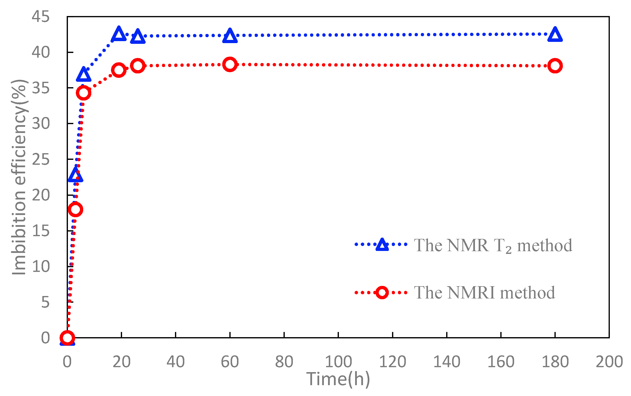
4.4. Recommended Methods to Calculate Imbibition Recovery

Using the two methods recommended in Methodology (Section 2), imbibition recovery curves of the two samples above are obtained in Figure 6 or Figure 7. The imbibition recoveries of two samples exceed 30% at 6 h after imbibition and keep stable after 19 h. The ultimate recoveries of the NMR T2 method are 35% and 42% respectively for SX-5 andYL-1, which is consistent with the recovery results using the imbibition bottle in our previous work. However, the ultimate recovery results of the NMRI method are 51% (SX-5) and 38% (YL-1). The recovery results show no obvious relationship with the permeability. Even the recovery results show differences. The imbibition recovery results still indicate that imbibition is critical for the development of tight oil reservoirs.
Comparisons between two methods in Figure 6 or Figure 7 were analyzed. On the one hand, as can be seen from Figure 6 or Figure 7, the two curves show the same trend with time. On the other hand, the imbibition recovery obtained by the NMRI method for SX-5 is always larger than that acquired by the NMR method, while the relationship is just opposite for YL-1. Reasons for the discrepancies are mainly attributed to the resolution of two methods and the heterogeneity of pore size distributions. The resolution of NMR T2 is much higher than that of 2D-images. The NMRI method cannot effectively identify oil changes in tiny pores during spontaneous imbibition. The NMR T2 and NMRI results can lead us to make the following remarks. Firstly, both tiny pores and large pores are abundant inYL-1 whereas the large pore content is high and tiny pore content is low in SX-5. Furthermore, the imbibition ability in large pores of YL-1 is weak while tiny pores show a strong imbition ability inYL-1. Not only tiny pores, but also large pores show a strong imbibition ability in SX-5. Here, the dominant imbibition pores are large pores whereas the dominant imbibition pores in YL-1 are tiny pores. Therefore, the imbibition recovery of SX-5 can be mostly contributed by the dominant imbibition pores when the imbibition recovery of YL-1 can be mostly contributed by a poor pore behavior. What’s more, the heterogeneity of pore size distributions in two samples aggravates this dicrepancy in the two methods.
Based on the results above, the NMR T2 method can effectively identify tiny and large pores, we recomend it as an effective tool for predicting imbibitoin recovery in tight sandstones. However, with the improvement of resolutions in NMRI, the imbibiton recovery predicted by the NMRI method will get more and more close to the recovery calculated by the NMR T2 method. In our future work, the relationship between the resolution of NMRI and predicted imbibition recovery will be studied.

5. Conclusions

In this study, two outcrop samples were collected to perform spontaneous imbibition experiments under AFO boundary condition. NMRI and NMR T2 tests were conducted during spontaneous imbibition, and employed to evaluate the spontaneous imbibition mechanism and the oil displacement recovery by imbibition. The main conclusions are as follows: (1) Spontaneous imbibition slows down and even ceases after 6 h. The oil signal in tiny pores stabilizes during the early stage of imbibition while the oil signal in large pores keeps fluctuating during the late stage of imbibition. (2) According to the results of NMRI and NMR T2, we conclude that continuous oil is cut off once water invades the whole core and then imbibition slows down or even ceases. The reason why the oil signal amplitude in pores, especially large pores, fluctuates at a late period of the experiment is that diffusion plays a dominant role in determining the distributions of discontinuous oil at the late stage. (3) The imbibition recovery of two samples using two methods exceeded 35%. Even differences occurred, the results still indicate that imbibition is critical for the development of tight oil reservoirs. (4) The two imbibition recovery curves that were predicted by the two methods are basically consistent. Discrepancies, however, still exist. Due to the differences of the resolutions of the two methods, there are some discrepancies in the imbibition recovery values. Furthermore, the heterogeneity of pore size distributions in the two samples aggravates this discrepancy between the two methods.

Author Contributions

Each author has made contributions to the present paper. Conceptualization, C.L., M.C., and Q.W.; Data curation, C.L. and Q.W.; Investigation, C.L., M.C., Q.W., and Z.N.; Writing—review & editing, C.L., Z.C., M.L. All authors have read and approved the final manuscript.

Acknowledgments

This research was funded by National Natural Science Foundation of China (51474222 and 51504265), PetroChina Innovation Foundation (2017D50070205) and the Foundation of State Key Laboratory of Petroleum Resources and Prospecting, China University of Petroleum, Beijing (No. PRP/open-1601).The authors will also gratefully appreciate the anonymous reviewers’ suggestions.

Conflicts of Interest

The authors declare no conflict of interest.

References

  1. Jia, C.Z.; Zou, C.N.; Li, J.Z.; Li, D.H.; Zheng, M. Assessment criteria, main types, basic features and resource prospects of the tight oil in Chin. Acta Petrol. Sin. 2012, 33, 343–350. [Google Scholar]
  2. Chen, M.Q.; Cheng, L.S.; Cao, R.Y.; Lyu, C.H. A Study to Investigate Fluid-Solid Interaction Effects on Fluid Flow in Micro Scales. Energies 2018, 11, 2197. [Google Scholar] [CrossRef]
  3. Lyu, C.; Ning, Z.; Wang, Q.; Chen, M. Application of NMR T2 to Pore Size Distribution and Movable Fluid Distribution in Tight Sandstones. Energy Fuels 2018, 32, 1395–1405. [Google Scholar] [CrossRef]
  4. Novlesky, A.; Kumar, A.; Merkle, S. Shale Gas modeling workflow: From microseismic to simulation-A horn river case study. In Proceedings of the Canadian Unconventional Resources Conference, Calgary, AB, Canada, 15–17 November 2011. [Google Scholar]
  5. Yang, L.; Ge, H.; Shi, X. The effect of microstructure and rock mineralogy on water imbibition characteristics in tight reservoirs. J. Nat. Gas Sci. Eng. 2016, 34, 1461–1471. [Google Scholar] [CrossRef]
  6. Meng, M.; Ge, H.; Ji, W. Monitor the process of shale spontaneous imbibition in co-current and counter-current displacing gas by using low field nuclear magnetic resonance method. J. Nat. Gas Sci. Eng. 2015, 27, 336–345. [Google Scholar] [CrossRef]
  7. Olafuyi, O.A.; Cinar, Y.; Knackstedt, M.A. Spontaneous imbibition in small cores. In Proceedings of the 2007 SPE Asia Pacific Oil & Gas Conference and Exhibition, Jakarta, Indonesia, 30 October–1 November 2007. [Google Scholar]
  8. Wei, W.; Cai, J.; Xiao, J.; Meng, Q.; Xiao, B.; Han, Q. Kozeny-Carman constant of porous media: Insights from fractal-capillary imbibition theory. Fuel 2018, 234, 1373–1379. [Google Scholar] [CrossRef]
  9. Li, C.X.; Shen, Y.H.; Ge, H.K.; Su, S.; Yang, Z.H. Analysis of spontaneous imbibition in fractal tree-like network system. Fractals 2016, 24. [Google Scholar] [CrossRef]
  10. Cai, J.; Perfect, E.; Cheng, C. Generalized modeling of spontaneous imbibition based on Hagen-Poiseuille flow in tortuous capillaries with variably shaped apertures. Langmuir 2014, 30, 5142–5151. [Google Scholar] [CrossRef] [PubMed]
  11. Alomair, O.A. New Experimental Approach for Measuring Drainage and Spontaneous Imbibition Capillary Pressure. Energy Fuels 2009, 23, 260–271. [Google Scholar] [CrossRef]
  12. Lyu, C.; Ning, Z.; Chen, M.; Wang, Q. Experimental study of boundary condition effects on spontaneous imbibition in tight sandstones. Fuel 2019, 235, 374–383. [Google Scholar] [CrossRef]
  13. Li, C.X.; Shen, Y.H.; Ge, H.K.; Yang, Z.H.; Su, S.; Ren, K.; Huang, H.Y. Analysis of capillary rise in asymmetric branch-like capillary. Fractals 2016, 24, 15–22. [Google Scholar] [CrossRef]
  14. Mason, G.; Fernø, M.A.; Haugen, Å.; Morrow, N.R.; Ruth, D.W. Spontaneous Counter-Current Imbibition outwards from a HemiSpherical Depression. J. Pet. Sci. Eng. 2012, 90–91, 131–138. [Google Scholar] [CrossRef]
  15. Cai, J.C.; Yu, B.M.A. Discussion of the Effect of Tortuosity on the Capillary Imbibition in Porous Media. Transp. Porous. Med. 2011, 89, 251–263. [Google Scholar] [CrossRef]
  16. Zhou, D.; Jia, L.; Kamath, J. Scaling of counter-current imbibition processes in low-permeability porous media. J. Petrol. Sci. Eng. 2002, 33, 61–74. [Google Scholar] [CrossRef]
  17. Zhou, D.; Jia, L.; Kamath, J. An Investigation of Counter-Current Imbibition Processes in Diatomite. In Proceedings of the SPE Western Regional Meeting, Bakersfield, CA, USA, 26–30 March 2001. [Google Scholar]
  18. Li, J.S. The Effect of Surfactant System on Imbibition Behavior. Ph.D. Thesis, Institute of Porous flow and Fluid Mechanics of Chinese Academy of Sciences, Beijing, China, 2006. [Google Scholar]
  19. Coates, G.R.; Xiao, L.; Prammer, M.G. NMR Logging Principles and Applications, 1st ed.; Halliburton Energy Services: Houston, TX, USA, 1999; ISBN 978-0967902609. [Google Scholar]
  20. Al-Yaseri, A.Z.; Lebedev, M.; Vogt, S.J. Pore-scale analysis of formation damage in Bentheimer sandstone with in-situ NMR and micro-computed tomography experiments. J. Petrol. Sci. Eng. 2015, 106, 48–57. [Google Scholar] [CrossRef]
  21. Morriss, C. Core analysis by low-field NMR. Log Anal. 1997, 38, 84–93. [Google Scholar]
  22. Yao, Y.; Liu, D.; Che, Y. Petrophysical characterization of coals by low-field nuclear magnetic resonance (NMR). Fuel 2010, 89, 1371–1380. [Google Scholar] [CrossRef]
  23. Baldwin, B.A.; Spinler, E.A. In situ saturation development during spontaneous imbibition. J. Petrol. Sci. Eng. 2002, 35, 23–32. [Google Scholar] [CrossRef]
  24. Li, M.; Romerozerón, L.; Marica, F. Polymer Flooding Enhanced Oil Recovery Evaluated with Magnetic Resonance Imaging and Relaxation Time Measurements. Energy Fuels 2017, 31, 4904–4914. [Google Scholar] [CrossRef]
  25. Song, Y.; Wang, S.; Yang, M. MRI measurements of CO2-CH4 hydrate formation and dissociation in porous media. Fuel 2015, 140, 126–135. [Google Scholar] [CrossRef]
  26. Jiang, T.; George Hirasaki, A.; Miller, C.; Moran, K.; Fleury, M. Diluted Bitumen Water-in-Oil Emulsion Stability and Characterization by Nuclear Magnetic Resonance (NMR) Measurements. Energy Fuels 2007, 21, 1325–1336. [Google Scholar] [CrossRef]
  27. Lai, F.P.; Li, Z.P.; Wei, Q.; Zhang, T.T.; Zhao, Q.H. Experimental Investigation of Spontaneous Imbibition in a Tight Reservoir with Nuclear Magnetic Resonance Testing. Energy Fuels 2016, 30, 8932–8940. [Google Scholar] [CrossRef]
  28. Chen, T.; Yang, Z.; Ding, Y.; Luo, Y.T.; Qi, D.; Wei, L.; Zhao, X.L. Waterflooding Huff-n-puff in Tight Oil Cores Using Online Nuclear Magnetic Resonance. Energies 2018, 11, 1524. [Google Scholar] [CrossRef]
  29. Oren, P.E.; Bakke, S.; Arntzen, O.J. Extending Predictive Capabilities to Network Models. SPE J. 1998, 3, 324–336. [Google Scholar] [CrossRef]
  30. Ruth, D.; Mason, G.; Morrow, N.R. A Numerical Study of the Influence of Sample Shape on Spontaneous Imbibition. In Proceedings of the International Symposium of the Society of Core Analysts, Pau, France, 21–24 September 2003. [Google Scholar]
  31. Li, H.; Guo, H.; Yang, Z. Tight oil occurrence space of Triassic Chang 7 Member in Northern Shaanxi Area, Ordos Basin, NW China. Petrol. Explor. Dev. 2015, 42, 434–438. [Google Scholar] [CrossRef]
  32. Valvatne, P.H.; Blunt, M.J. Predictive pore-scale modeling of two-phase flow in mixed wet media. Water Resour. Res. 2004, 40, 187–187. [Google Scholar] [CrossRef]
  33. Kleinberg, R.L.; Farooqui, S.A. T1/T2 ratio and frequency dependence of NMR relaxation in porous sedimentary rocks. J. Colloid. Interface Sci. 1993, 158, 195–198. [Google Scholar] [CrossRef]
  34. Kleinberg, R.L.; Straley, C.; Kenyon, W.E.; Akkurt, R.; Farooqui, S.A. Nuclear magnetic resonance of rocks: T1 vs. T2. In Proceedings of the SPE Annual Technical Conference and Exhibition, Houston, TX, USA, 3–6 October 1993. [Google Scholar]
Figure 1. Counter-current imbibition in oil-saturated cores under AFO boundary condition.
Energies 11 02359 g001
Figure 2. T2 distributions of core SX-5 during imbibition.
Energies 11 02359 g002
Figure 3. T2 distributions of coreYL-1 during imbibition.
Energies 11 02359 g003
Figure 4. 2D images of SX-5 during imbibition.
Energies 11 02359 g004
Figure 5. 2D images of YL-1 during imbibition.
Energies 11 02359 g005
Figure 6. The imbibition recovery of SX-5 predicted by the NMR T2 method and the NMRI method.
Energies 11 02359 g006
Figure 7. The imbibition recovery of YL-1 predicted by the NMR T2 method and the NMRI method.
Energies 11 02359 g007
Table 1. Mineral contents, porosity, permeability and contact angle of two samples.
SamplePetrophysical PropertyX-ray Results/%
L/cmR/cmK/mDϕ/%So/%θQzPlCalDolTCCM
SX-53.992.520.219.796.549.369.48.51.15.016
YL-13.832.520.8910.298.340.582.7---17.3
Note: L—core length, R—core radius, K—permeability, ϕ—porosity, So—oil saturation, θ—contact angle; Qz—quartz, Pl—plagioclase, Cal—calcite, Dol—dolomite; TCCM represents the total content of clay minerals.

