1. Introduction
The rapid development of microelectronic technology poses an important challenge for high-heat-flux electronic cooling [
1]. A number of efficient cooling technologies, including microchannels [
2,
3,
4,
5], heat pipes [
6], boiling [
7], solid–liquid change [
8], fractal surface [
9,
10] and liquid cooling [
11,
12], have been proposed and are used for electronic component cooling [
13], spacecraft thermal control [
14], microfluidic engineering [
15] and battery thermal management [
16]. Of these, the flat two-phase thermosyphon has been regarded as the preferred heat removal technique in a confined space [
17,
18]. Differing from conventional heat pipes, the evaporator and condenser section of the flat two-phase thermosyphon are replaced by two plates. Therefore, the flat two-phase thermosyphon can expand one-dimensional heat transfer into two-dimensional heat transfer on a plane, resulting in an efficient heat transfer and satisfactory temperature uniformity [
19]. Utilized in a solar collector system, the two-phase thermosyphon combines good energy behavior with simplicity of manufacture [
14,
15,
16,
17]. In addition, the flat two-phase thermosyphon can be integrated with electronic devices [
20]. Therefore, the flat two-phase thermosyphon has been introduced as an effective way to meet the challenges of heat dissipation and temperature uniformity for high-heat-flux electronic devices.
Unlike in unconfined spaces, the vapor-liquid phase change inside a flat two-phase thermosyphon involves a direct interaction between boiling and condensation accompanied by complex gas–liquid two-phase flow behaviors because of the narrow space [
21]. For example, when the liquid level in the cavity is high, the liquid surface may contact the condenser surface because of the two-phase flow fluctuation, which forms a “liquid bridge” between the liquid surface and the condenser surface because of the surface tension. The formation of a liquid bridge may increase the thermal resistance of the condenser surface as the liquid film thickness increases [
22]. In addition, Wu et al. [
23] reported that, instead of gravity and buoyancy, the surface tension and the shear force at the gas–liquid interface are the dominant forces affecting the gas–liquid two-phase flow during boiling and condensation in the flat two-phase thermosyphon. Therefore, the coupled boiling–condensation process has a non-negligible effect on the gas–liquid two-phase flow behavior and heat transfer process [
24] in flat two-phase thermosyphons.
Available experimental and theoretical studies of flat two-phase thermosyphons focused primarily on the steady-state thermal performance, such as temperature uniformity [
25,
26], equivalent thermal conductivity [
27], thermal resistance [
28], and maximum heat transfer capacity. In addition, a number of studies have been conducted to investigate the coupled boiling–condensation heat transfer in a confined space [
17,
21,
29]. However, few studies have given attention to the thermal response and corresponding gas–liquid two-phase flow in the flat two-phase thermosyphon, specifically the boiling and condensation behaviors under the startup and quasi-steady processes. Visual representation of vapor–liquid two-phase flow is of significance to understand the coupled boiling–condensation phase change heat transfer inside flat two-phase thermosyphons. Therefore, a visualization experiment was conducted to investigate the gas–liquid phase change heat transfer. The startup modes and operating state in the flat two-phase thermosyphon are investigated and analyzed by the observed dynamic temperature variations of the evaporator and condenser surface as well as the gas–liquid two-phase interface evolution.
2. Description of Experiment
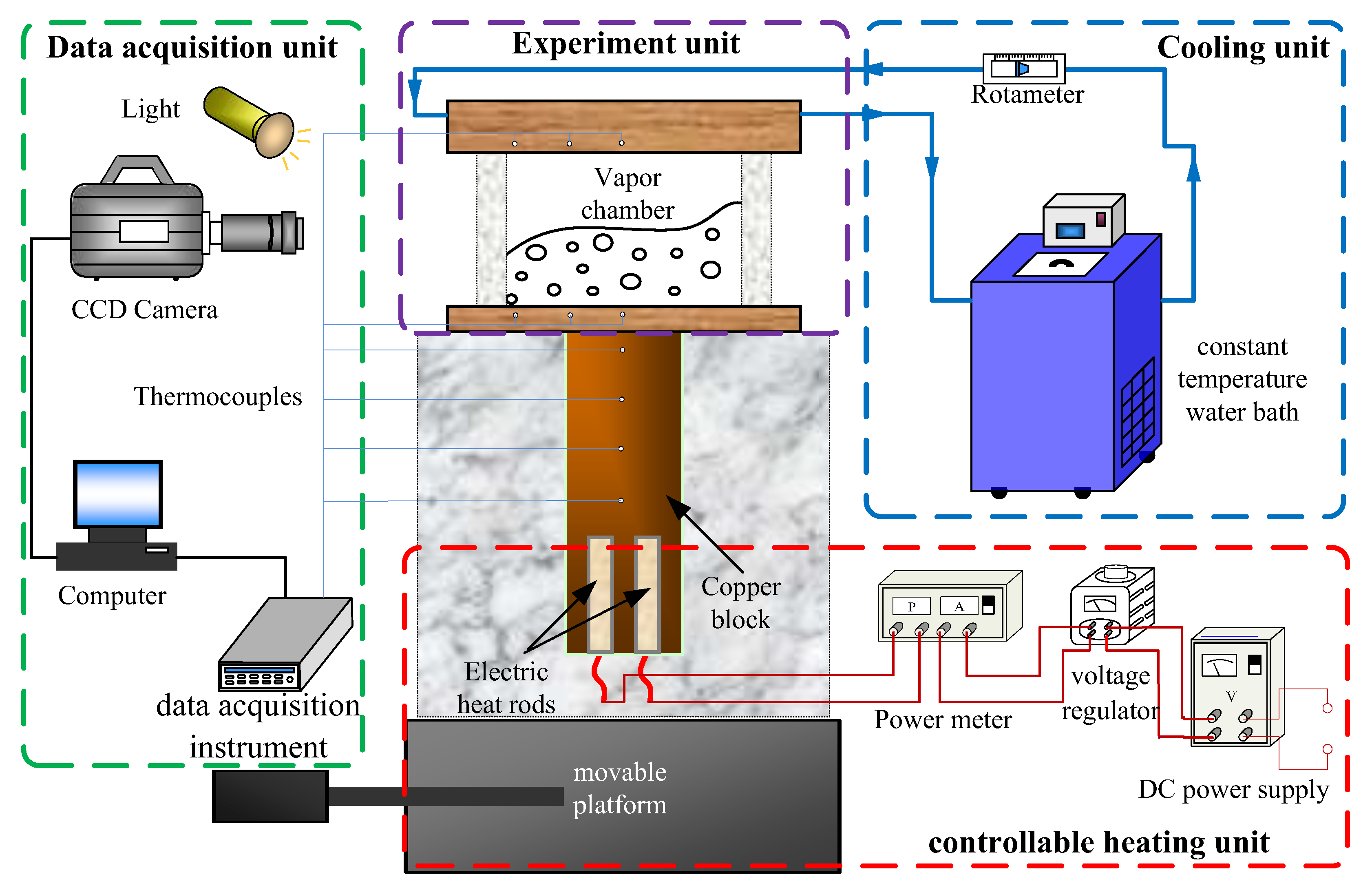
In order to visualize the vapor–liquid two-phase flow, a flat two-phase thermosyphon was manufactured with transparent sidewalls. The visualization experimental setup, as shown in
Figure 1, includes the flat two-phase thermosyphon, a heating unit, a cooling unit, and a data acquisition unit. The gas–liquid two-phase behavior and the coupled evaporator–condenser heat transfer process are observed in the flat two-phase thermosyphon with this experimental setup.
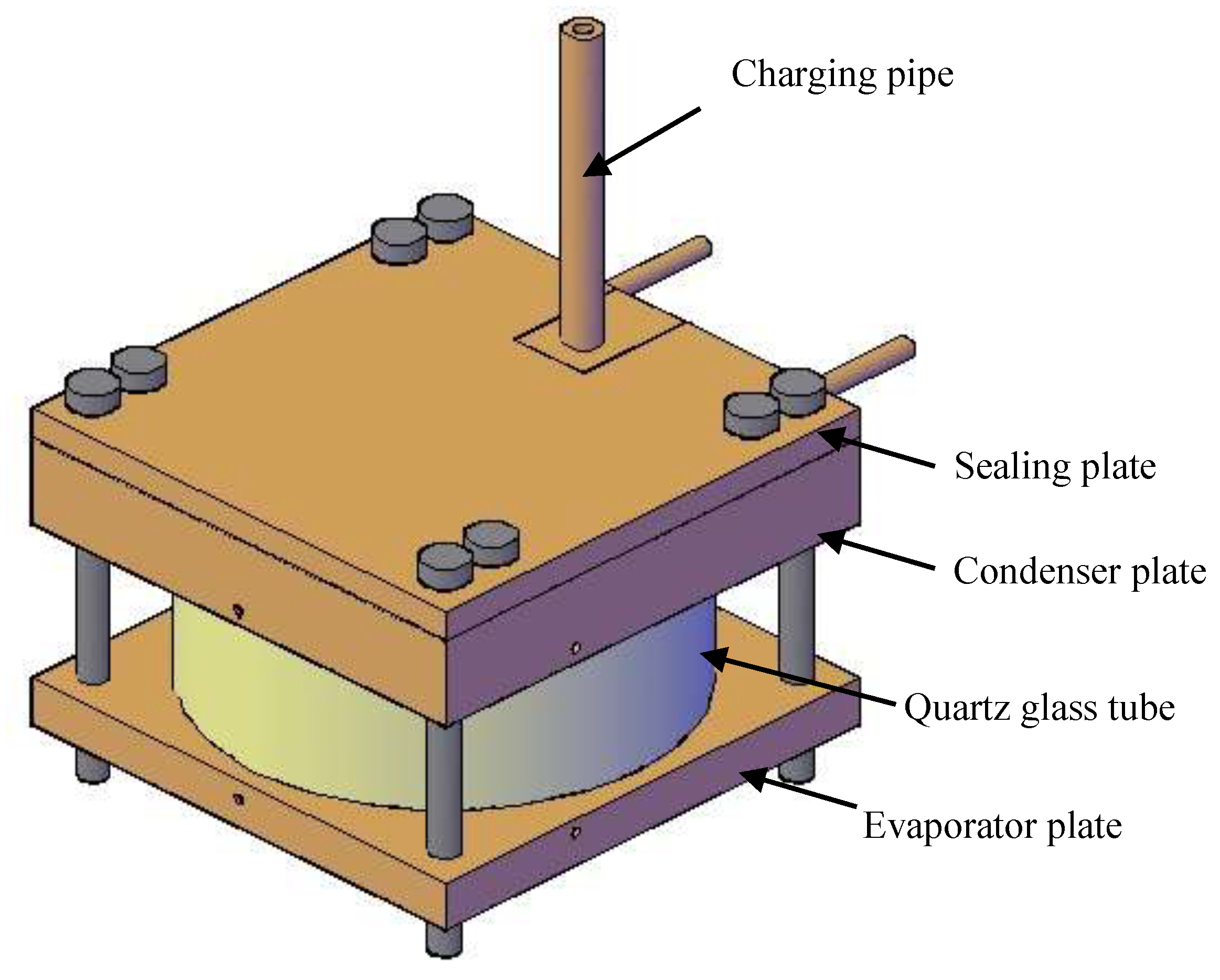
The flat two-phase thermosyphon primarily comprises a quartz glass tube, an evaporator plate, a condenser plate, a sealing plate of heat sink, and a charging pipe, as shown in
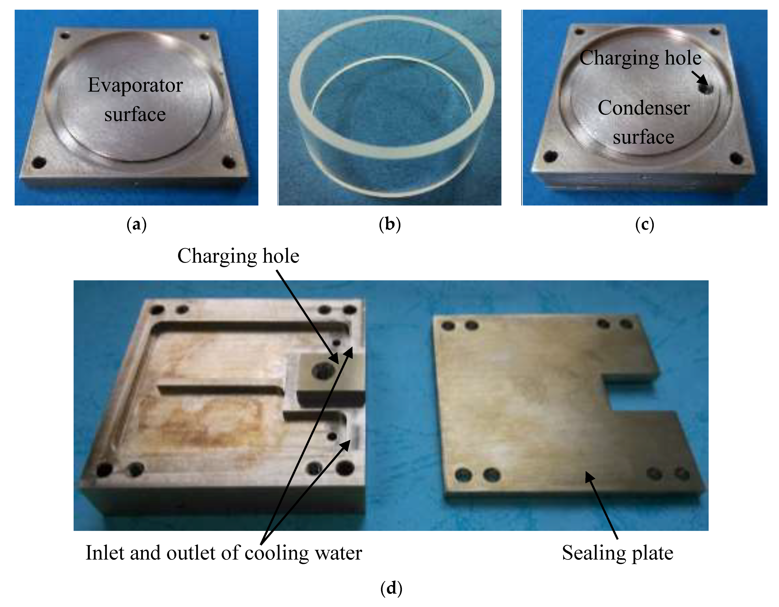
Figure 2. The various components of the flat two-phase thermosyphon are illustrated in
Figure 3. The glass tube is tightly clamped between the evaporator and condenser plates, and a close cavity is formed where the working medium is filled. The outer diameter of glass tube is 50 mm and the inner diameter is 44 mm. For clear observation of the vapor–liquid two-phase flow in the flat two-phase thermosyphon, a height of 15 mm was used for the glass tube during the experiment. Annular grooves were milled on the evaporator and condenser plates and were filled with fluorine rubber O-rings for sealing the flat two-phase thermosyphon. The evaporator and condenser sections are square brass plates with 45-mm sides, as shown in
Figure 3. The thickness of the evaporator plate is 5 mm, while that of the condenser plate is 10 mm. A cooling channel is set on the back of the condenser plate; therefore, a sealing plate is needed for the sealing of the cooling water. The working medium is fed into the cavity through the charging pipe. In this study, de-ionized water was used as the working medium, as shown in
Table 1.
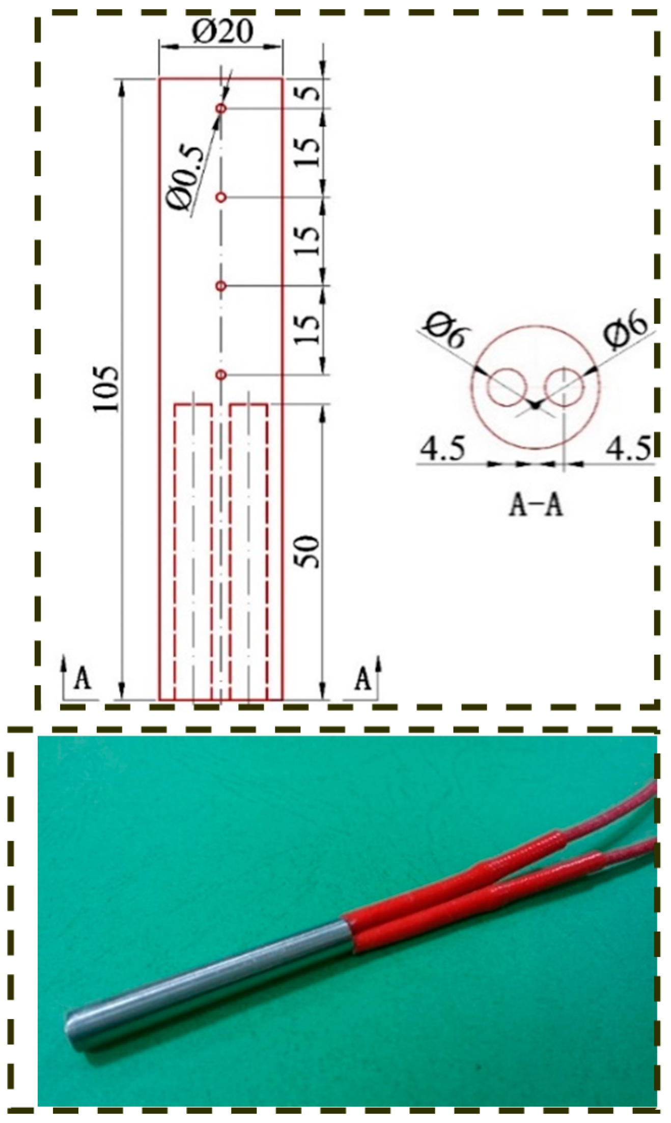
The heating unit, which is used to provide and control a heat source for the flat two-phase thermosiphon, is supplied by a direct current power combined with a voltage regulator. Electric heating rods are embedded in the bottom of a copper block to heat the evaporator and a power meter is paralleled with the heating rods to measure the heating power, as shown in
Figure 4. The electric heating rods are 6 mm in diameter and 50 mm in length. The 20-mm diameter copper block is clamped by a bracket comprising a number of polytetrafluoroethylene plates, so that the copper block can make close contact with the evaporator section of the flat two-phase thermosyphon. To obtain the accurate axial heat flux density of the copper block, four 0.5-mm diameter holes were drilled to a depth of 10 mm in the copper block. The holes were distributed along the axial direction of the copper block, and the distance from the holes to the top surface of the copper block are 5 mm, 20 mm, 35 mm, and 50 mm, as shown in
Figure 5. During the experiment, heating power ranging from 20–90 W was applied to examine the effect of heat load on vapor–liquid two-phase flow.
The cooling unit is connected to the condenser section of the flat two-phase thermosyphon, and comprises a constant temperature water bath and a glass rotameter. The constant temperature water bath provides a constant-temperature fluid circulation for the cooling of the condenser section, and the flow rate of the circulating water is measured by the glass rotameter. In the experiment, the water temperature was set to room temperature of 25 °C, and the flow rate of the circulating water was set to 80 mL/min. In order to measure the sensible heat gain of the circulating water, a number of thermocouples were installed at the inlet and outlet of the condenser section. The sensible heat gain is determined as the heat load of the flat two-phase thermosyphon. The cooling heat transfer rate is Qcool = ρVCpΔTcool, where ρ and Cp are the density and specific heat of the cooling water, respectively, and ΔTcool is the temperature difference between the cooling water at inlet and outlet.
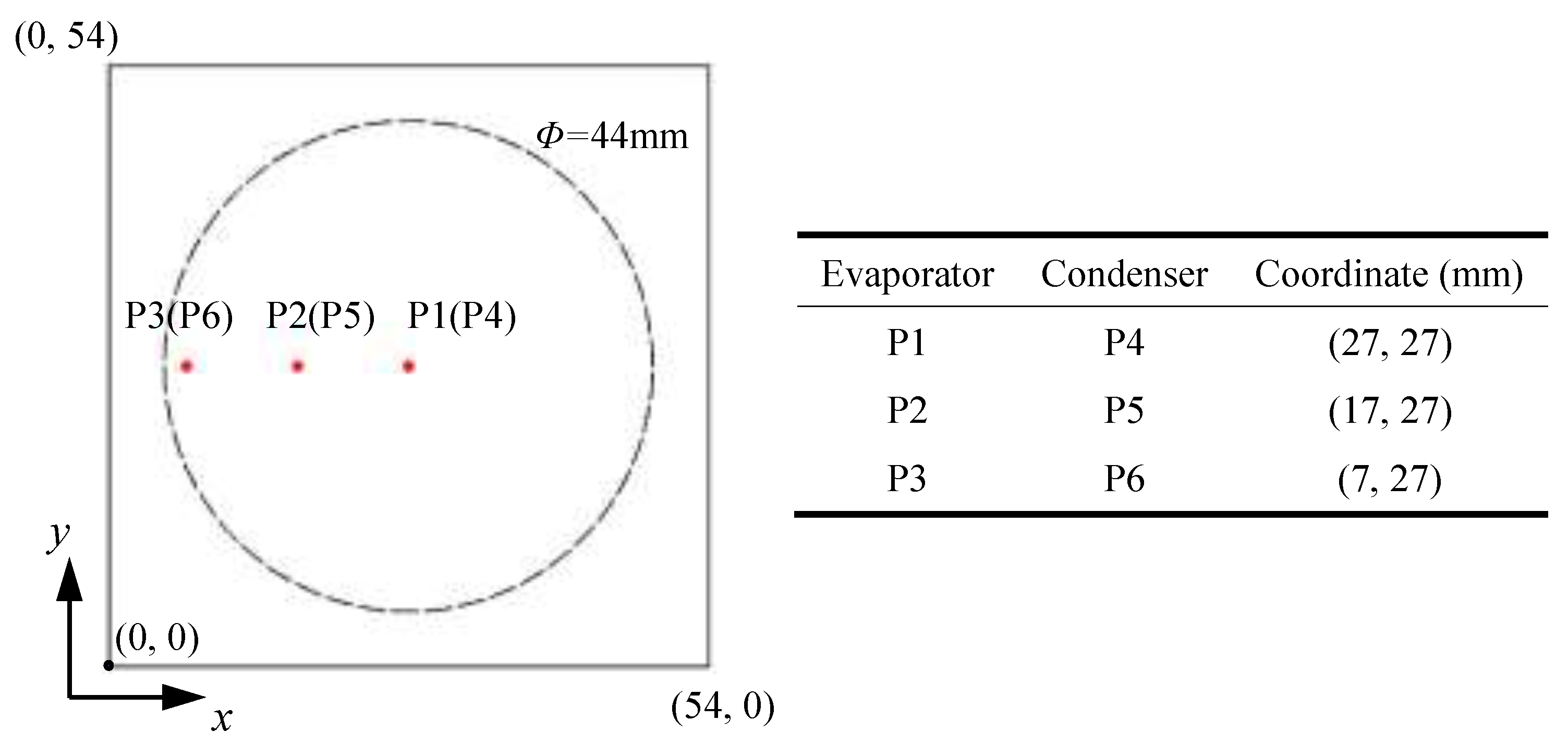
The data acquisition unit comprises a charge-coupled device (CCD) camera, a data collector (Agilent 34970A, Santa Clara, CA, USA), a computer, and a light. The vapor–liquid two-phase behavior in the confined cavity of the flat two-phase thermosyphon was monitored in real time and recording was started when the flat two-phase thermosyphon operated. The frame rate of CCD was set to 500 fps. To record the dynamic temperature variations of evaporator and condenser surfaces, three thermocouples (see
Figure 5) were installed on the evaporator and condenser surfaces. The temperature was recorded by the data acquisition instrument. The sampling rate for the acquisition of the temperature is 2 Hz.
3. Results and Discussion
The vapor–liquid two-phase state inside the cavity is directly related to the wall temperature of the evaporator and condenser section, and, therefore, determines the phase change mechanisms and thermal performance of the flat two-phase thermosyphon [
30]. An experiment was conducted to visually monitor the operating state of the working medium inside the cavity during the start-up and the quasi-steady processes. Based on the observed vapor–liquid two-phase state and the measured wall temperatures of the condenser and evaporator sections under different working conditions, it is possible to analyze the startup modes and operating states of a flat two-phase thermosyphon.
3.1. Startup Modes
When the evaporator section is heated, the flat two-phase thermosyphon initially goes through a start-up process and then attains a quasi-steady operating state. During the start-up process, the bubbles start to generate on the evaporator surface, and then gradually increase in size and rise from the surface. As a result, a complex two-phase vapor–liquid is formed close to the evaporator surface because of the dual effect of the natural convection and bubble disturbance. According to the dynamic temperature variations of the evaporator surface, two startup modes are identified for the flat two-phase thermosyphon: sudden startup mode and gradual startup mode.
The difference of two startup modes is mainly caused by the filling rate, i.e., the thermal response is largely dependent on the charging ratio. A larger degree of superheating is required to induce the startup of the flat two-phase thermosyphon when the charging ratio is higher. However, small superheating is required to induce the startup when the charging ratio is low. Therefore, different startup modes appear even though the heat input remains the same. The charging ratio φ is defined as the ration of the working fluid volume to the interior volume of thermosyphon.
3.1.1. Sudden Startup Mode
As shown in
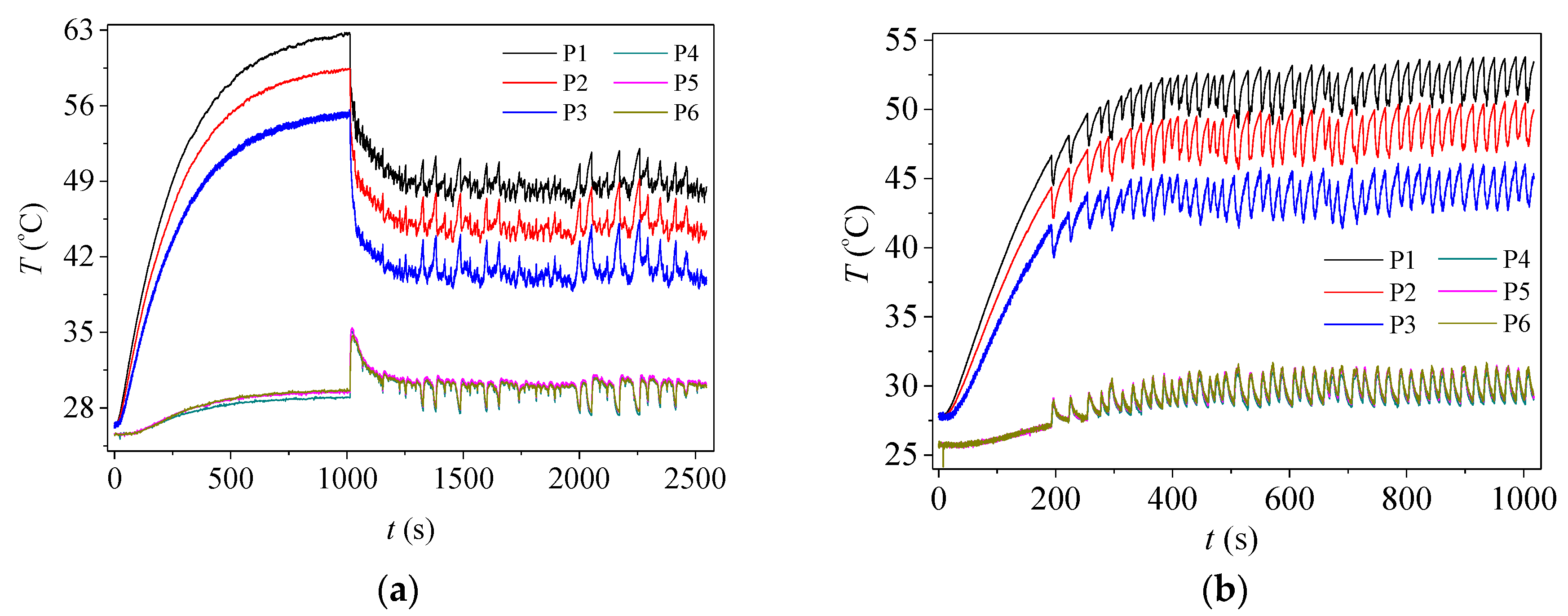
Figure 6a, in the sudden startup mode, the wall temperature of the evaporator section rises rapidly initially without temperature fluctuations, and the vapor–liquid two-phase working medium remains stationary in the early startup stage. Subsequently, the wall temperature continues to increase gradually, and no bubbles are generated inside the two-phase thermosyphon. During this process, a significant degree of superheating is required to induce the startup of the flat two-phase thermosyphon. The input heat flux is absorbed as sensible heat thorough the working medium and solid wall; therefore, the energy continues to be absorbed in the thermosyphon. As can be seen from the figure, at approximately 1000 s, the evaporator wall temperature suddenly decreases by approximately 10 °C (i.e., a temperature overshoot occurs in the startup process), and the condenser wall temperature suddenly rises by approximately 7 °C. Subsequently, there is a pronounced temperature pulsation for the condenser and evaporator walls.
This can be explained by the fact that, over time, the significant degree of superheating because of the continued accumulation of energy breaks the critical equilibrium state of the vapor–liquid two-phase working medium and bubbles begin to form on the evaporator surface and grow rapidly, and then leave the evaporator surface, causing a strong disturbance of the liquid surface [
31]. When the vapor comes into contact with the condenser surface, it condenses to form condensate droplets and returns to the evaporation section because of the effect of gravity. The heat absorbed by the evaporator section is rapidly transmitted to the condensation section through the generation of bubbles and the condensation of vapor, and then the condenser and evaporator surface temperatures gradually attain an equilibrium state. Therefore, it can be concluded that the sudden startup is an overshoot startup process, in which the maximum surface temperature of evaporator section in the startup process is significantly greater than the value of steady-state wall temperature.
3.1.2. Gradual Startup Mode
In contrast to the sudden startup mode, there is no wall temperature overshoot in the gradual start-up mode, as shown in
Figure 6b. The wall temperature of the evaporator section shows a significant pulsation after a short pre-heating period (approximately 200 s), and periodic variations of bubble formation, growth, and detachment from the evaporator surface can be observed inside the flat two-phase thermosyphon. Subsequently, increases in the departing frequency and the number of bubbles generated on the evaporator surface lead to a slow rise in the evaporator and condenser wall temperatures. Over time, the evaporator and condenser wall temperatures gradually become stable, and finally enter a steady state.
It can be seen from the figure that, during the entire startup process, the temperature change from the initial time to the steady state is gradual. This is because the bubbles increase in size shortly after the evaporator is heated in the gradual startup mode, i.e., a small degree of superheat is required for the formation of the critical bubble core. Therefore, the heat input into the evaporator section can be rapidly transmitted through the phase change process of the working fluid. As a result, a gradual increase of the evaporator section wall temperature (no overshoot) is observed in the gradual startup mode.
3.2. Operating States
The working fluid in the flat two-phase thermosyphon enters a quasi-steady state after the startup process. According to the wall temperature pulsation characteristics and visual images of the vapor–liquid two-phase fluid, three quasi-steady operating states are experienced in sequence with increasing heat load: continuous large-amplitude pulsation state (State A), alternate pulsation state (State B), and continuous small-amplitude pulsation state (State C).
3.2.1. Continuous Large-Amplitude Pulsation State (State A)
State A typically occurs when the evaporator section is supplied with a small heat load. As shown in
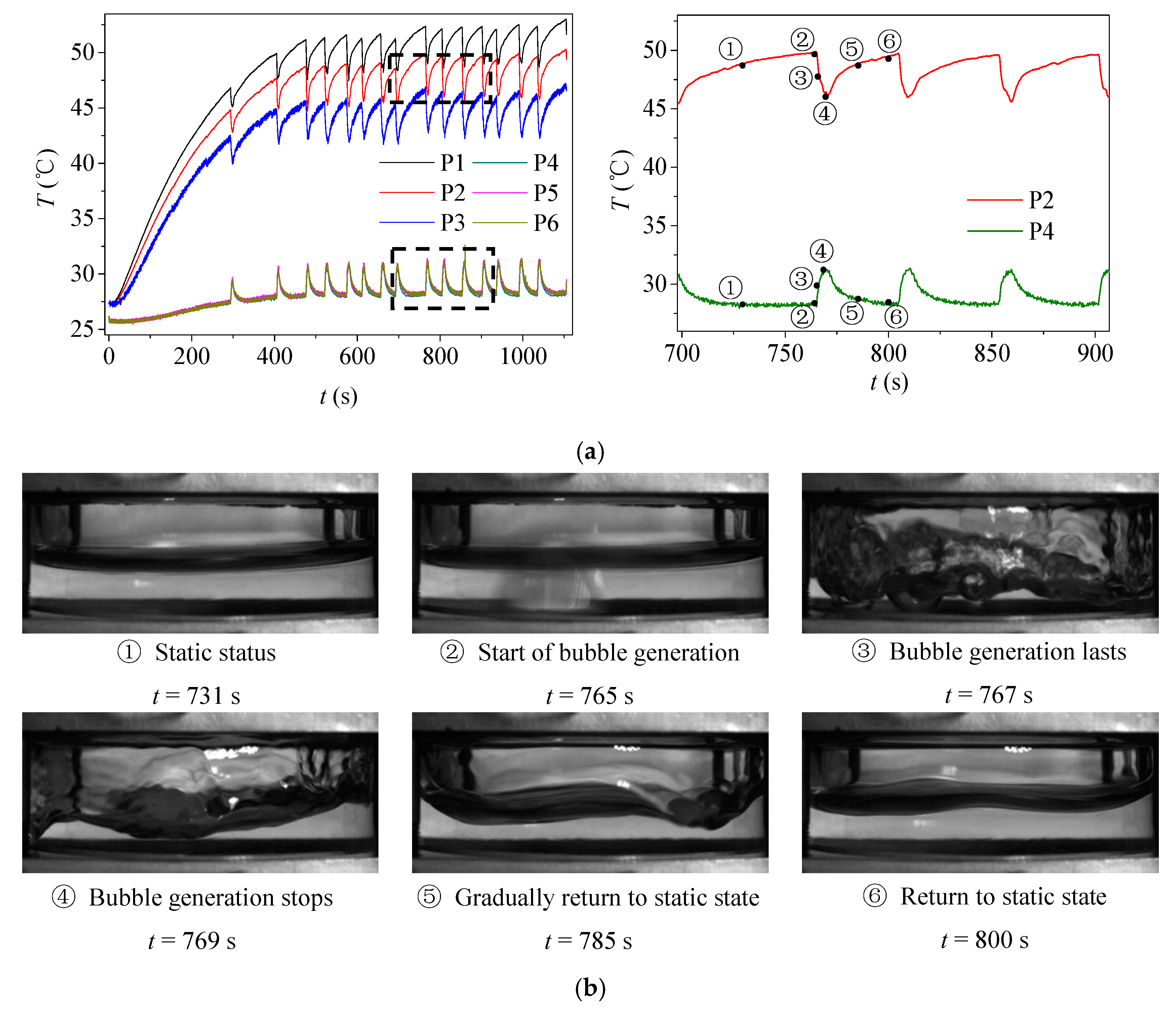
Figure 7, during the first tens of seconds of a typical cycle, the liquid is superheated in the evaporator section and remains in the static status, while the vapor is cooled in the condenser section. When a critical degree of superheat is achieved, the liquid starts boiling and bubbles are generated. In the boiling process, the bubble generation only lasts for a few seconds, accompanied by a sudden large fluctuation in temperature; then the liquid returns to the static state and goes into the next cycle. The static status and boiling status can be clearly distinguished during this process. In this operating state, the wall temperature of the evaporator section fluctuates cyclically with a continuous large amplitude, where only a monotonic increase and decrease of the wall temperature are experienced in a typical cycle. Because of the small heat load, the energy absorption rate in the cavity is relatively slow, and bubbles are generated intermittently on the surface of the evaporator section. The following energy phases of the evaporation section are repeated cyclically until the end of the heat input: accumulation, release, re-accumulation, and re-release. In this process, the fluid inside a thermosyphon experiences boiling, stagnation, re-boiling, and re-stagnation.
In order to intuitively exhibit the features of a large-amplitude pulsation cycle,
Figure 7b shows the wall temperature pulsation of the evaporator and condenser sections from 700 to 900 s, which includes four cycles of continuous large-amplitude pulsation. One pulsation cycle is from 700 to 769 s.
Figure 7c shows the typical gas–liquid two-phase behavior for a pulsation cycle, for which the corresponding time points and wall temperatures are marked by point 1 to point 6 in
Figure 7b. During the cycle, the fluid remains in a static state from
t = 731 s (point 1) to
t = 765 s (point 2), and the wall temperature of the evaporator section gradually increases because of the energy accumulation. When the wall temperature increases to point 2, the degree of superheat reaches a critical value. As a result, the nucleation sites on the evaporation surface are activated and bubbles are generated continuously. Because of the bubble motion and vapor–liquid phase change, energy is rapidly transferred from the evaporator section to the condenser section, resulting in a significant decrease in the evaporator temperature and a rapid increase in the condenser temperature.
It should be noted that the continuous bubble generation (point 3) is of short duration and only lasts for approximately 4 s. After t = 769 s (point 4), the wall temperature of the evaporator section decreases; the degree of superheat is smaller than the critical value, causing bubble generation to cease, so the liquid gradually returns to the static state (point 5) and the energy absorption starts again in the next cycle (point 6). It can be seen that the heat accumulation in the evaporator section is of short duration in this operating state because of the small heat input, and the heat can be rapidly transferred to the condenser section through the motion of the vapor bubbles. Therefore, bubble generation is only observed for a short period.
3.2.2. Alternate Pulsation State (State B)
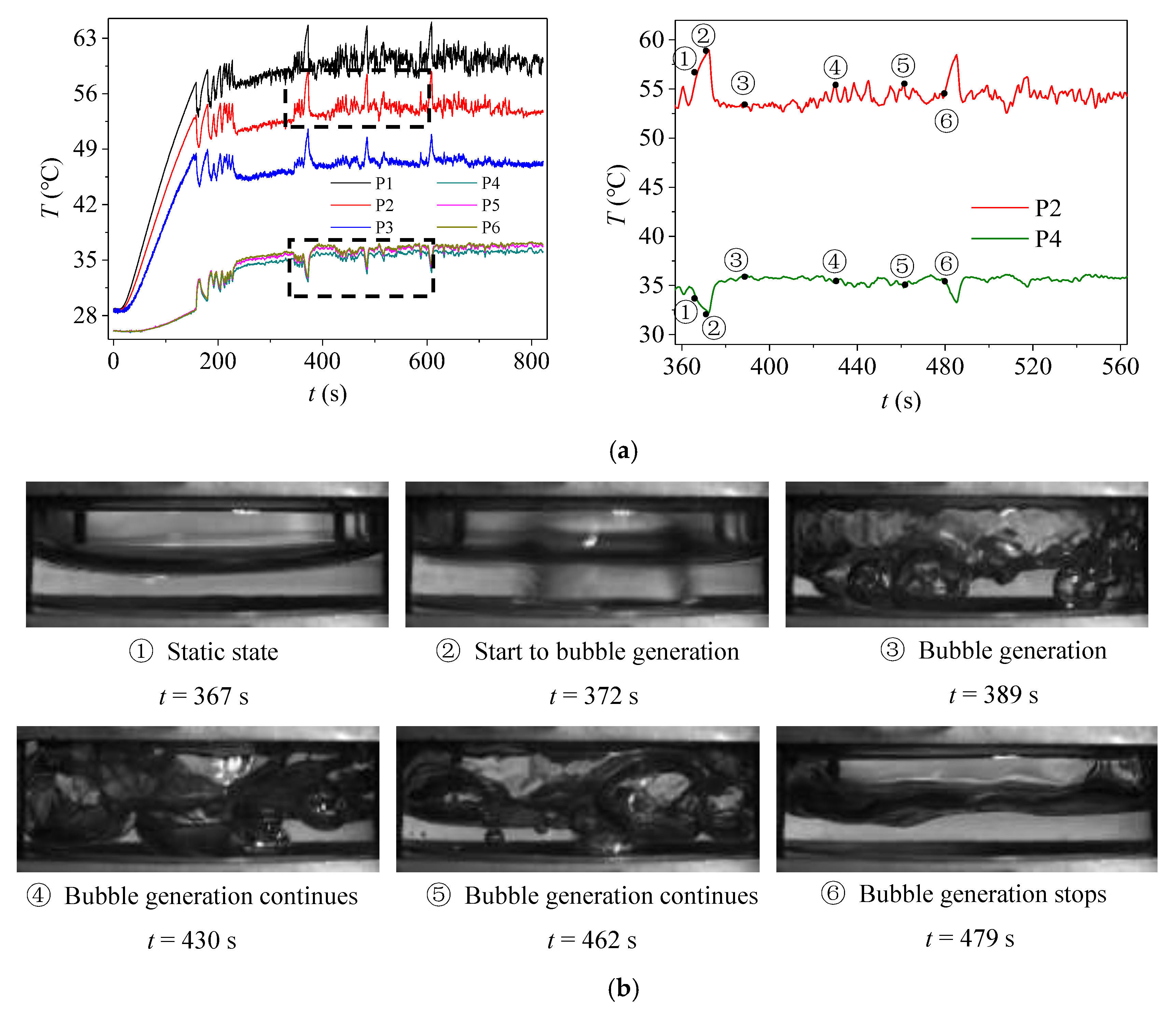
When compared with State A, the energy accumulation is accelerated with increasing heat input, so the duration of static status becomes shorter while the boiling status lasts longer in State B. As the bubble generation frequency increases, the pressure perturbation appears in the cavity, leading to the small amplitude fluctuation of wall temperature. In State B, the wall temperature of the evaporator section shows a fluctuation with small amplitude in addition to the large-amplitude fluctuations, and it exhibits a similar cyclical fluctuation. According to the pulsation amplitude and its duration for the wall temperature of evaporator section, State B can be divided into two alternate pulsation types. One is characterized by a long-duration single large-amplitude pulsation alternating with multiple short-duration small-amplitude pulsations (State B–1), and the other is characterized by a single short-duration large-amplitude pulsation alternating with multiple long-duration small-amplitude pulsations (State B–2).
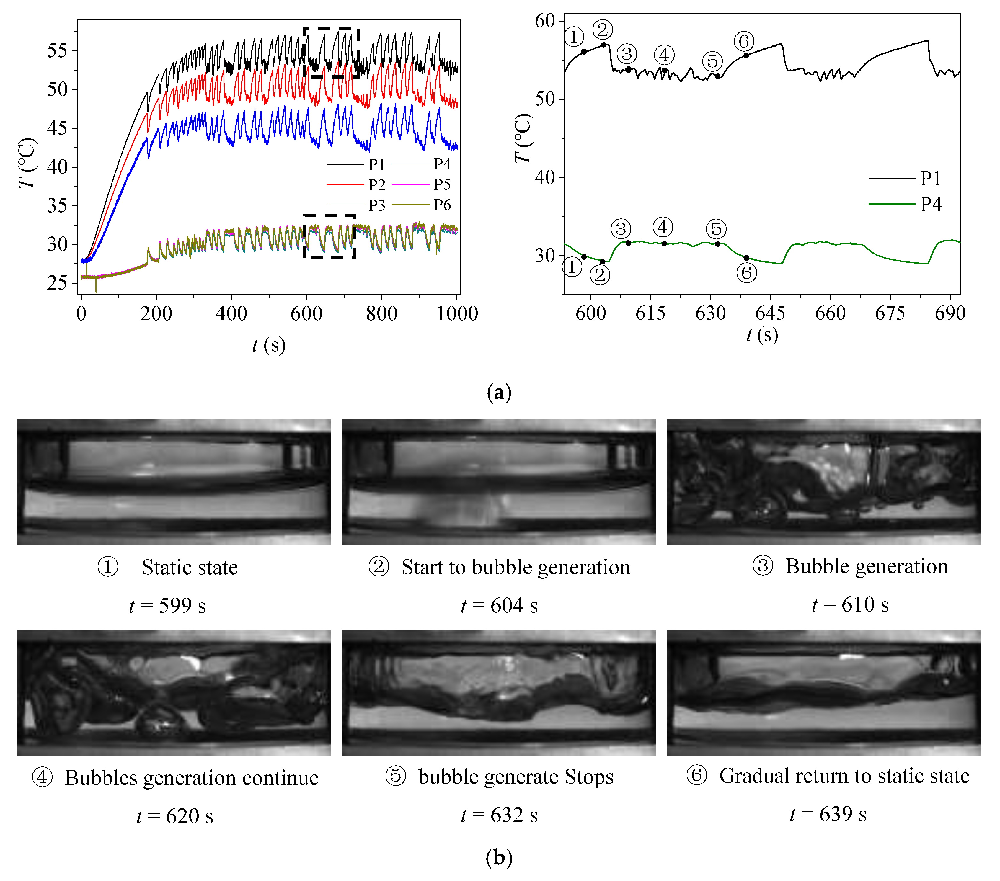
Figure 8 shows the wall temperature pulsation and the corresponding gas–liquid two-phase flow behavior for State B–1 for the flat two-phase thermosyphon, in which three wall temperature cycles (from 590–690 s) are enlarged. As shown in the figure, the early stage of a cycle (from point 1 to point 2, 590–604 s) can be characterized by large-amplitude fluctuations, and the energy continues to be absorbed and the temperature slowly increases without fluctuations. Bubble generation then begins on the evaporator surface, and this process lasts for 28 s, significantly longer than for State A, as the heat input increases. It is noteworthy that after the bubble generation has commenced, the wall temperature decreases rapidly in the evaporator section and increases in the condenser section (from point 2 to point 3). Subsequently, the temperature exhibits multiple small-magnitude fluctuations (from point 3 to point 5). This can be attributed to the random generation and detachment of bubbles on the evaporator surface and the scouring effect of the gas–liquid two-phase fluid on the condenser surface. In this case, the wall temperatures of both the evaporator and condenser sections pulsate with small amplitudes close to the steady state. However, as the heat input is still not sufficient, the proportion of small-magnitude temperature pulsations to the entire pulsation cycle is small, i.e., the number of large-magnitude temperature pulsations dominates a cycle.
With a further increase in the heat input, the operating state of State B–1 is transformed into State B–2.
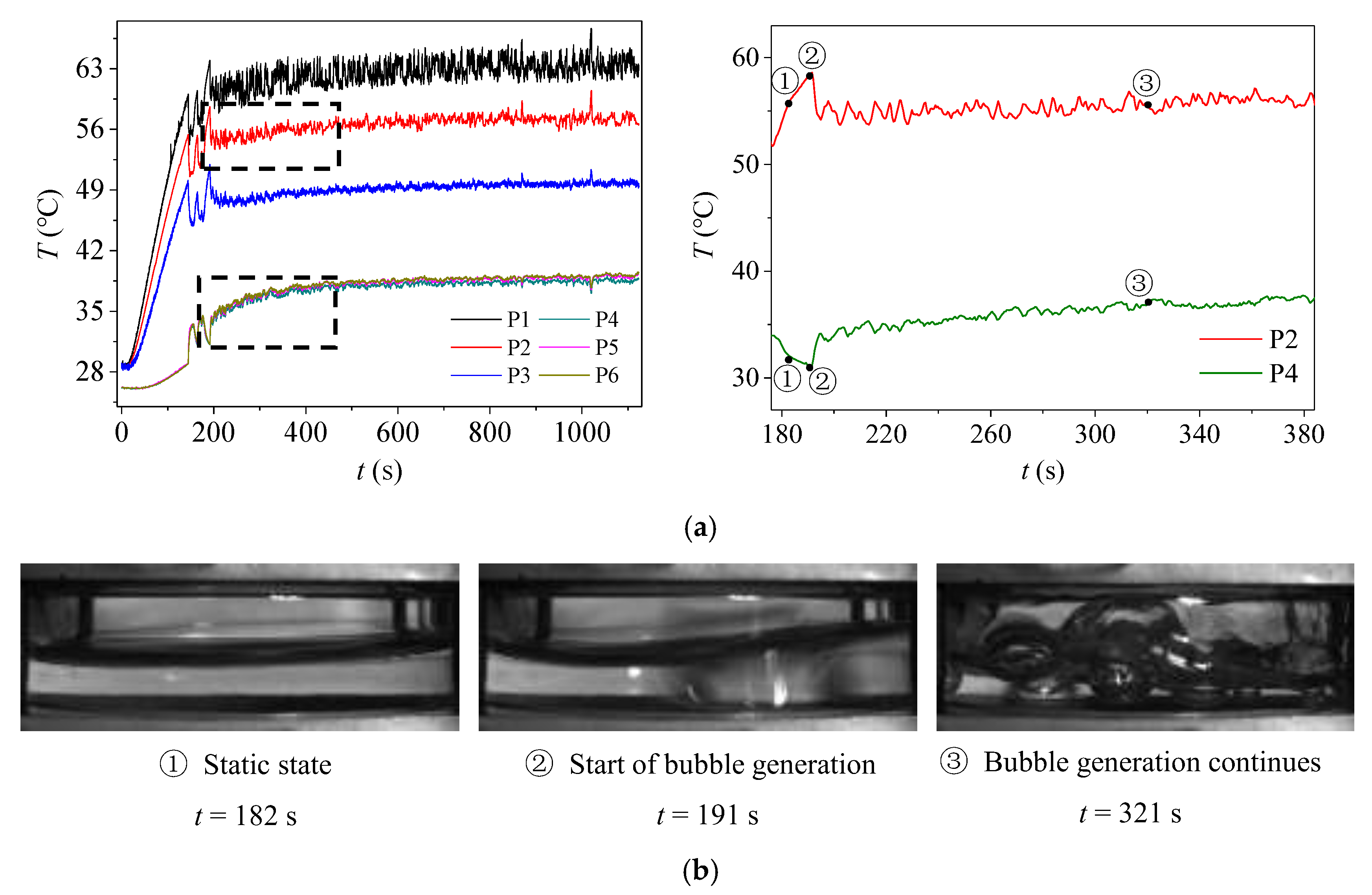
Figure 9 shows the wall temperature pulsations and the corresponding gas–liquid two-phase flow behavior in State B–2. Compared with State B–1, the duration of the small-magnitude pulsations is significantly greater in State B–2, and the duration of continuous bubble generation increases to approximately 100 s (from point 2 to point 6 in
Figure 9a). The interval between bubbles decreased, and for the bulk of the time bubbles were generated continuously and rising from the evaporator surface, resulting in a significant fluid disturbance. According to the gas–liquid two-phase behavior images, it can also be seen that the disturbance of the working fluid amplifies with the heat input in the flat two-phase thermosyphon, which is favorable for the enhancement of heat transfer process. As a result, the heat input is efficiently transferred from the evaporator section to the condenser section through the intense gas–liquid phase change.
3.2.3. Continuous Small-Amplitude Pulsation State (State C)
When the heat input is sufficiently great, the liquid is continuously boiling due to the intrinsically stochastic nature of liquid, resulting in continuous small-amplitude pulsation of wall temperature. In this case, the operating state enters a continuous small-amplitude pulsation state. Compared with the above operating states, there is no large-amplitude pulsation of wall temperature in State C as the boiling takes place continuously; there is no cyclical variation of wall temperature oscillation, and the wall temperature variation is random.
Figure 10 shows the dynamic temperature variation of both the evaporator and condenser walls in State C. Once bubble generation begins in the cavity (point 2 in
Figure 10), the bubbles are continuously generated on the evaporation wall. The wall temperature exhibits a small amplitude fluctuation, as opposed to a major change.
During the continuous small-amplitude pulsation state, there is no obvious cycle. Once bubble generation begins in the cavity, the bubbles continuously generate on the evaporation wall. This phenomenon can be explained as follows: (1) the vapor–liquid phase-change heat transfer between the evaporator and the condenser becomes stronger in State C, where the stable boiling and condensation in the cavity ensure efficient heat transfer; (2) the phase change processes (including evaporation and boiling) on the evaporator surface are strengthened, and the nucleation sites on the evaporator surface are more easily activated and generate bubbles; (3) more bubbles are generated on the evaporator surface (see point 3 in
Figure 10) than for the other operating states, and the liquid is more disturbed by the bubble motion. In summary, greater energy transfer intensity between the evaporator and condenser sections is achieved in the flat two-phase thermosyphon through efficient vapor–liquid phase changes.
3.3. Thermal Resistance
According to the above analysis, the heat load directly determines the operation state of vapor–liquid two phase flows inside a flat two-phase thermosyphon. This inevitably affects the thermal performance of evaporation and condensation phase change. In order to analyze the relationship between the heat transfer performance and heat load, the total thermal resistance of the flat two-phase thermosyphon
R is introduced, defined by
where
is the difference between the average temperature of the evaporator surface,
, and the average temperature of the condenser surface,
; and
Q is the actual heat load of the thermosyphon.
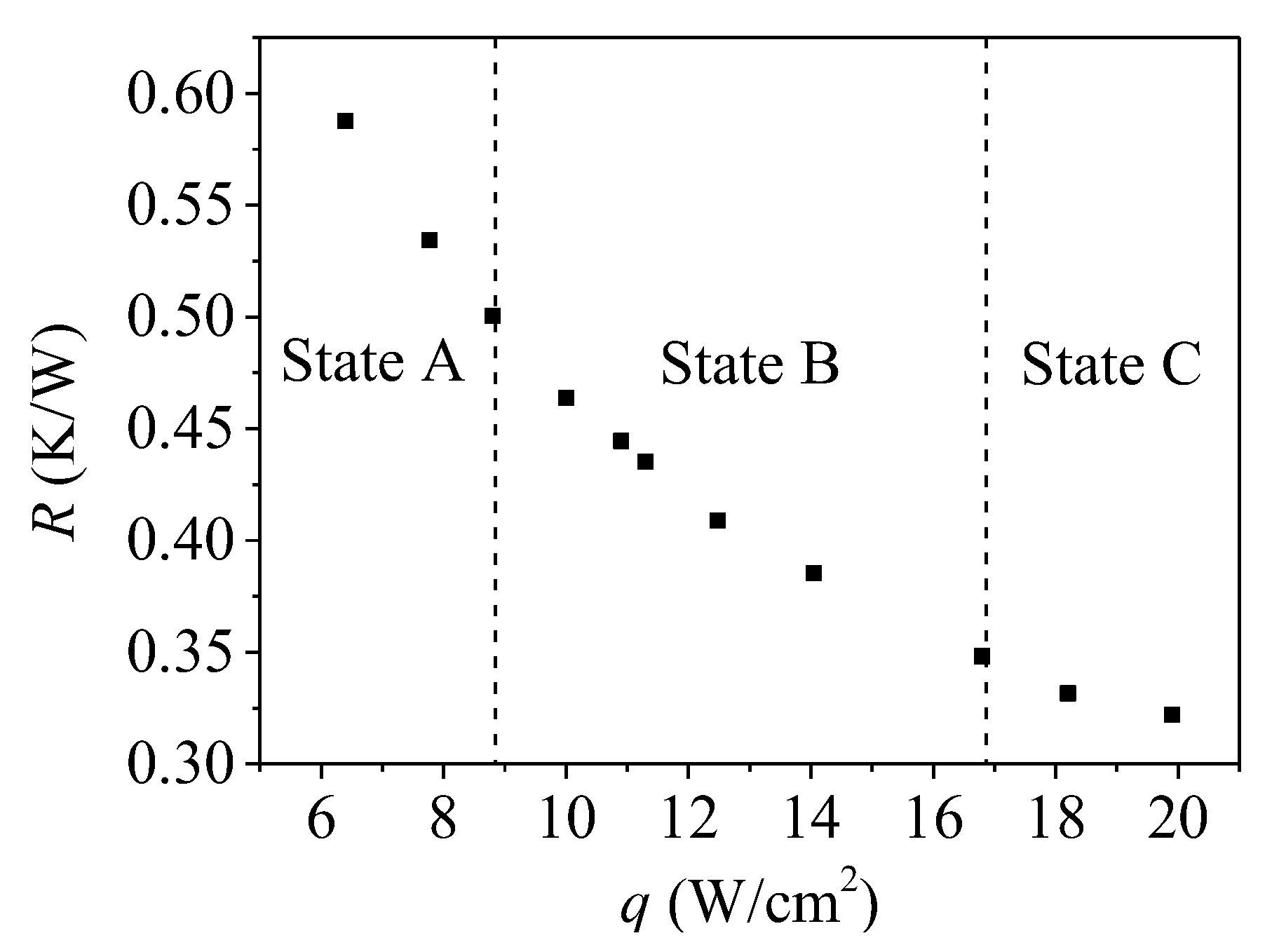
Figure 11 describes the effect of heat load on total thermal resistance of a flat two-phase thermosyphon. During the continuous large-amplitude pulsation state (State A), the heat load is small, and the bubbles are generated intermittently on the evaporator surface, so the heat transfer regime is the alternation of natural convection and nucleate boiling. In addition, the natural convection occupies most of time. This leads to a large thermal resistance of two-phase thermosyphon. When the operation state transforms from State A to the alternate pulsation state (State B), more heat is transferred through the bubble generation on the evaporator surface, i.e., the duration of nucleate boiling is longer. In addition, the motion of the bubbles causes the disturbance of the liquid near the evaporator surface, which also enhances heat transfer of the thermosyphon. The nucleate boiling occupies the most of time for State B. Since the good heat transfer performance of nucleate boiling, the total thermal resistance of State B is smaller than that of State A.
Unlike State A and B, during the continuous small-amplitude pulsation state (State C), the input heat is transferred wholly through nucleate boiling. Furthermore, the continuously generated bubbles cause a significant fluid disturbance, so the scouring effect of the gas–liquid two-phase fluid on the condenser surface make the condensate film thinner. This further reduces the thermal resistance as compared with State B. Therefore, as the thermal load increases, the thermal resistance of the flat two-phase thermosiphon decreases monotonously, thereby exhibiting better heat transfer performance. In other words, the thermal performance of alternate pulsation state in a flat two-phase thermosyphon is inferior to continuous small-amplitude pulsation state but superior to continuous large-amplitude pulsation state.


