1. Introduction
Shipping is considered as one of the most economical transportation ways in the world and it has played an important role in the development of world economy. However, with the expansion of world trade volume and the increase of energy demand for shipping, various environmental problems that are caused by shipping industry have also become increasingly prominent. In the 21st century, the energy used by ships must be sustainable [
1]. In recent years, extensive research has been conducted on the application of clean energies, such as liquefied natural gas (LNG), fuel cells, wind energy, and solar energy on ships, and many remarkable results have been achieved. However, as primary energy sources, clean energies, such as LNG and solar energy, cannot be directly applied to electrical equipment or power equipment on ships, but have to be converted into electrical energy or other secondary energy sources through energy conversion devices. In addition, clean energy sources are all low-density energy sources, and the application of a single clean energy source is very limited. When considering the differences in terms of ship structure, navigation areas and operating characteristics, the hybrid ship technology based on the comprehensive utilization of multiple energy sources has triggered a new round of research boom [
2].
In recent years, the solar ship application technology has achieved rapid development, and many successful real-ship application cases have been reported [
3,
4,
5,
6,
7,
8,
9].
In 2000, Australia designed a solar ship named ‘Solar Sailor’. It was the world’s first commercial solar/wind hybrid twin-hull passenger ship. In 2005, solar panels and large-capacity rechargeable batteries were widely installed on the ship—‘Euphony Ace’ designed in Japan. The world’s first solar hybrid large cargo ship, ‘Auriga Leader’, appeared in 2008, which had a length of 200 m and a total weight of 60,213 t, and it could carry 6400 vehicles. In 2010, ‘Shangde Guo Shen’ with solar energy and diesel as hybrid power was designed by China, which could save power and reduce emissions by more than 30%. In 2016, Singapore designed an unpiloted solar boat named ‘Solar Voyager’, which had a length of 5.5 m, a width of 0.76 m, and a top speed of 5 km/h. In the same year, China carried out a large-scale solar ship research project. The target ship had a capacity of 5000 parking spaces. In the target ship, 540 solar panels were installed to form a solar photovoltaic system, with a total capacity of 143 kW.
In the above cases, solar energy must be combined with other power sources or energy storage devices to provide power for the ship system, because it is an intermittent source of energy that can only produce electricity under good weather conditions. Meanwhile, the conversion efficiency of solar energy to electricity is relatively low. Moreover, due to the limitation of installable size, solar energy can only provide lighting or auxiliary power for the ship system. Fortunately, hybrid energy sources can be combined to overcome the inherent limitations of single energy sources. However, multiple energy units inevitably increase the complexity of the system. In view of this, appropriate energy management strategies should be proposed to make a hybrid system that is composed of multiple energy units work stably, reliably, and efficiently [
10].
At present, most research work that is associated with energy management strategies of hybrid power systems focuses on the distributed energy systems in automobiles or on the land. The methods can be roughly divided into three categories: (1) rule-based control algorithms, including logic-threshold control [
11] and fuzzy logic control [
12,
13]; (2) optimal control based on various algorithms, including instantaneous optimization [
14,
15] and global optimization [
16,
17]; and, (3) intelligent control based on various algorithms, such as wavelet algorithm, neural network algorithm [
18], and other control algorithms that are based on machine learning, multi-objective optimization, etc. [
19,
20,
21]. Among these, the fuzzy logic control has become a hot topic due to its high tolerability to system mathematical model and easy-to-implement rules.
In Refs. [
22,
23], a hybrid system of batteries and supercapacitors was simulated, and the fuzzy logic control method was adopted to control the output power and the charging-discharging process. The results showed that the fuzzy logic control strategy could improve the system efficiency and life time. In Refs. [
24,
25,
26,
27], the fuzzy logic control strategy was adopted to perform energy management on a fuel cell/battery hybrid system. It was found that the working performance of the fuel cell and the accumulator could be optimized effectively, thus improving the fuel economy of the vehicle. In Refs. [
28,
29], the fuzzy logic control strategy was used for hybrid systems consisting of fuel cells, batteries and supercapacitors, and good control results were achieved in terms of optimizing the performance of each energy unit and improving the system economy. In Reference [
30], a hybrid power system consisting of diesel generators, a solar energy system, and batteries was investigated, and the cuckoo search algorithm was used to optimize the output power of each power source. The results showed that the optimized full-load current (FLC) input, i.e., the battery and grid power demand, could minimize the loss of system power and reduce the energy consumption.
In recent years, along with the development of renewable energy ships, many studies on energy management strategies for hybrid ships have been conducted. By adopting different energy management strategies, such as adaptive model predictive control [
31], interval optimization [
32], multi-objective optimization [
33,
34], genetic algorithm [
35], instantaneous optimization [
36], equivalent cost minimization strategy [
37,
38], predictive control [
39], linear programming [
40], parallel control [
41], and online real-time optimization strategy [
42,
43], the output power of each power source can be optimized. These studies provide certain reference values for the research on energy management of solar hybrid systems.
From the easy-to-implement point of view, energy management strategies that are based on the fuzzy logic control are more suitable for real solar hybrid ships. On the one hand, the fuzzy logic control is very suitable for highly nonlinear control systems. On the other hand, ships are generally affected by winds, waves, and currents during normal sailing conditions, and the load of ships changes along with the variation of the environment, so the power demand of ships is stochastic and uncertain. In addition, the energy generated by the solar photovoltaic system varies with the sunlight intensity, which is also stochastic and uncertain. Therefore, it is very difficult to establish an accurate mathematical model for the highly nonlinear ship control systems. In this case, the adoption of fuzzy logic control is an ideal choice.
In this paper, a 5000-car space solar/diesel hybrid ro-ro ship is used as the research objective to establish reasonable fuzzy logic rules for each energy source by real-time monitoring on the ship load demand, solar photovoltaic system power generation, and battery charging state. Then, the output power of the energy sources can be reasonably distributed and optimized to cut down on fuel consumption and reduce emissions on the premise of meeting the ship’s power demand. The rest of this paper is organized as follows.
Section 2 introduces the design scheme of the target ship and hybrid power system.
Section 3 establishes the fuzzy logic energy management strategy. Then, the energy management strategy is verified by simulation and real ship testing in
Section 4.
Section 5 analyzes and evaluates the economic benefits of installing a solar hybrid system on a ship. Finally, some conclusions are drawn in
Section 6.
2. Design of Solar Hybrid Power System
The target ship in this paper is an ocean-going auto ro-ro ship, the ‘COSCO Tengfei’, which belongs to the China Ocean Shipping (Group) Corporation. The ship is equipped with a main engine of 14,520 kW, which can provide the propulsion power. Three diesel generators are installed to provide electricity for all electrical loads on the ship. Based on the original power system, the ship is modified by installing a new photovoltaic system. The technical parameters of the ship are shown in
Table 1.
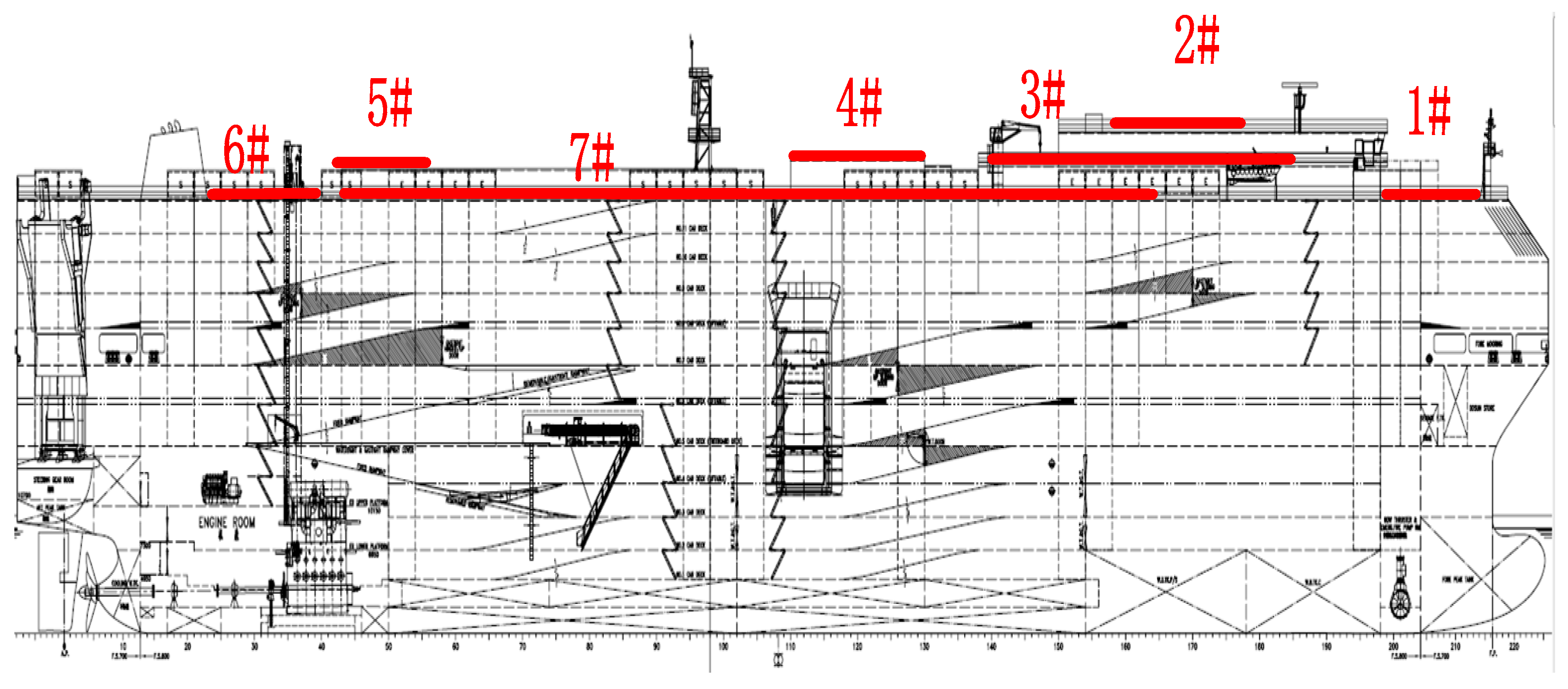
According to the ship structure, there are seven areas that are suitable for the installation of the solar photovoltaic system, including the front of the bow bridge (number 1#), the top of the bridge (number 2#), the deck U-shaped area (number 3#), the emergency generator room and the top of the CO
2 room in the middle of the ship (number 4#), the rear part of the ship’s rear heliport (number 5#), the area before the ship’s tail windlass (number 6#), and the boardwalk on both sides (number 7#). According to simple calculation, the total area available for the installation of solar panels in the seven areas is approximately 1300 m
2, as shown in
Figure 1.
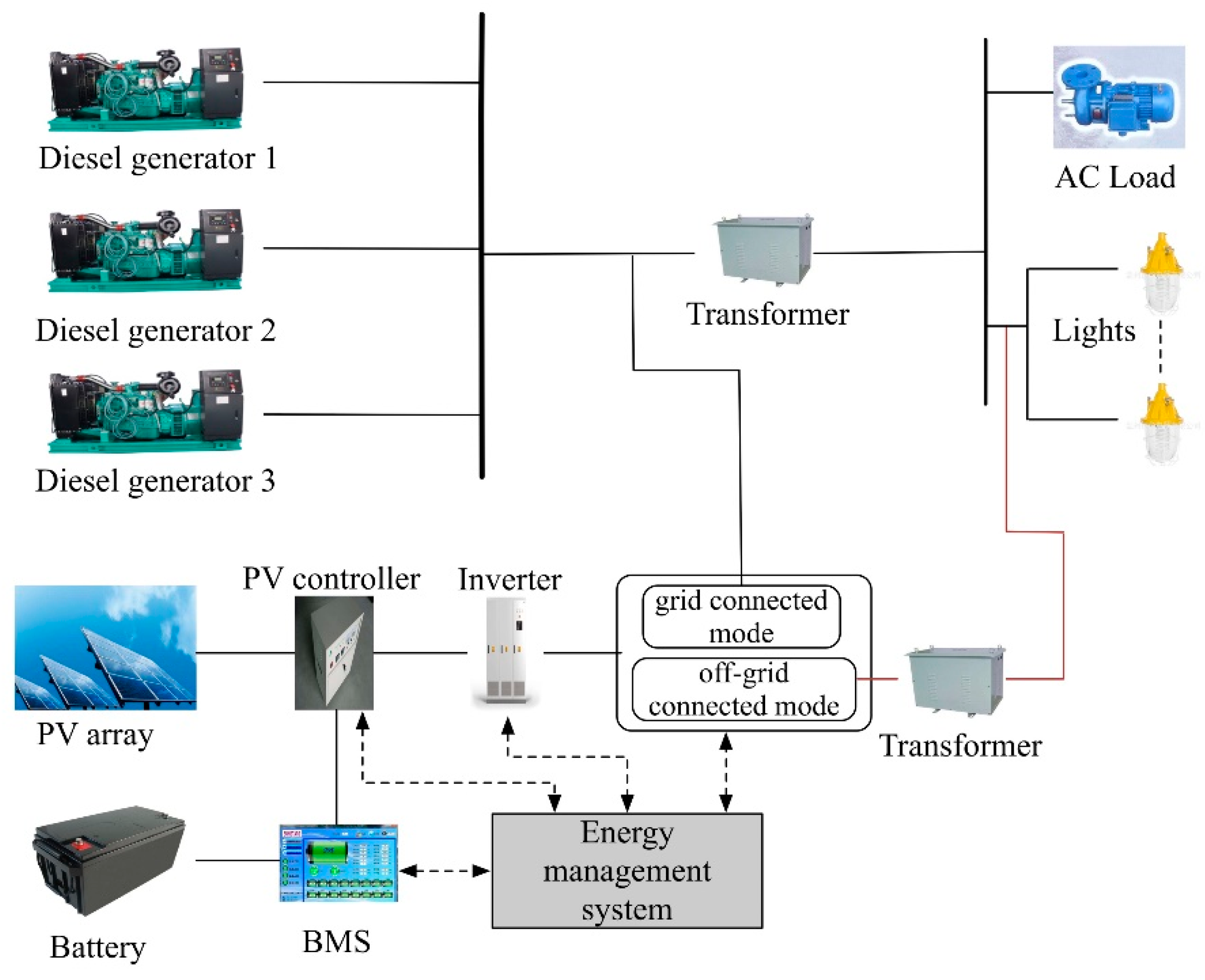
The total installed capacity of the solar photovoltaic system is 143 kWp. The unified stand-alone/grid-tied technology is adopted. The overall structure of the hybrid power system is shown in
Figure 2.
The system has two operation modes. In the stand-alone mode, the inverter transforms the solar energy and the battery power into 450 V of alternating current (AC), which is then stepped down by a three-phase transformer directly to supply the lighting system on the ship. In the grid-tied mode, the inverter converts the solar energy and the battery power into 450 V of AC and ties it to the power grid directly, which is then used to power the ship lighting system and other loads. The solar controller has the functions of data acquisition, workflow display, fault alarm, influencing factor analysis for photovoltaic power generation, and power generation situation report. To facilitate historical data check and failure analysis, all collected data are stored in the host computer. In addition, the system can realize remote data transmission through the 3 G network.
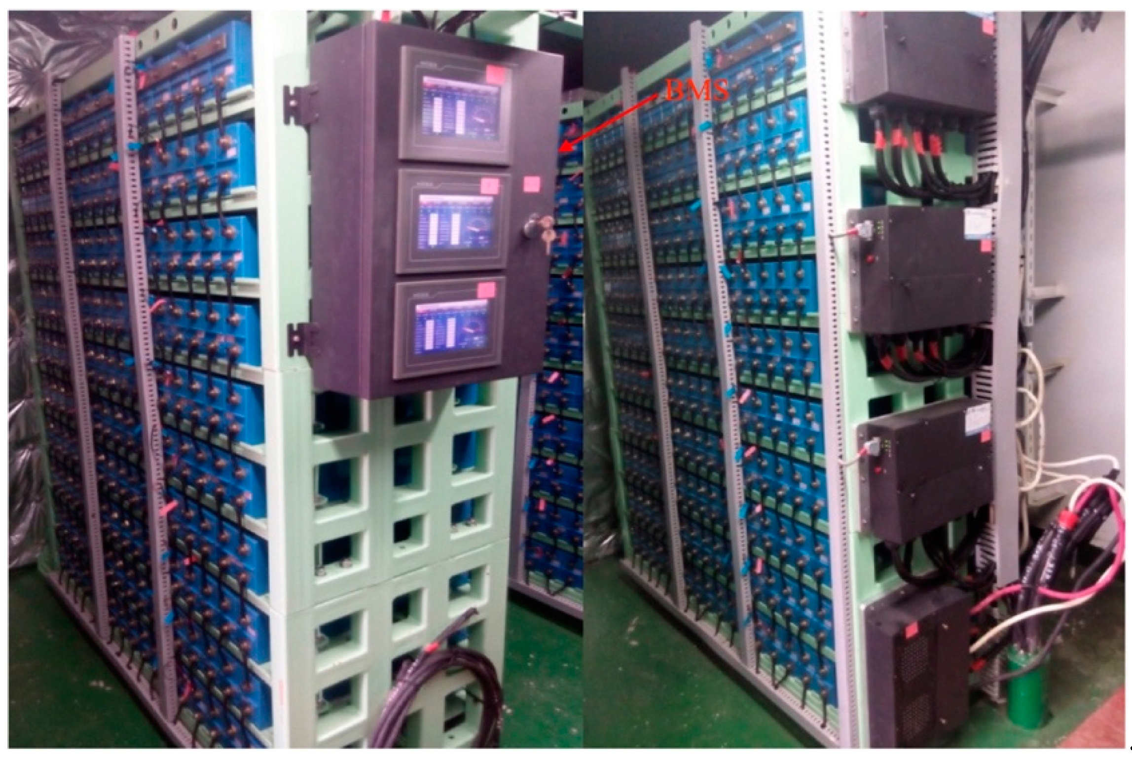
The large-capacity battery energy storage system adopts 3.2 V/100 Ah lithium-ion battery, and the battery output voltage is designed to be 384 V of direct current (DC). Through the combination of 120 units in series for one string and then 17 strings in parallel, the total capacity of the energy storage system can reach 652.8 kWh (as shown in
Figure 3). Each group of batteries is equipped with a battery management system (BMS), and the battery packs are balanced by smart real-time control. The BMSs can protect the battery packs from overcharge, overdischarge, and overtemperature. Besides, they can collect the state of charge (SOC) conditions, total voltage, and temperature of the battery packs in real time.
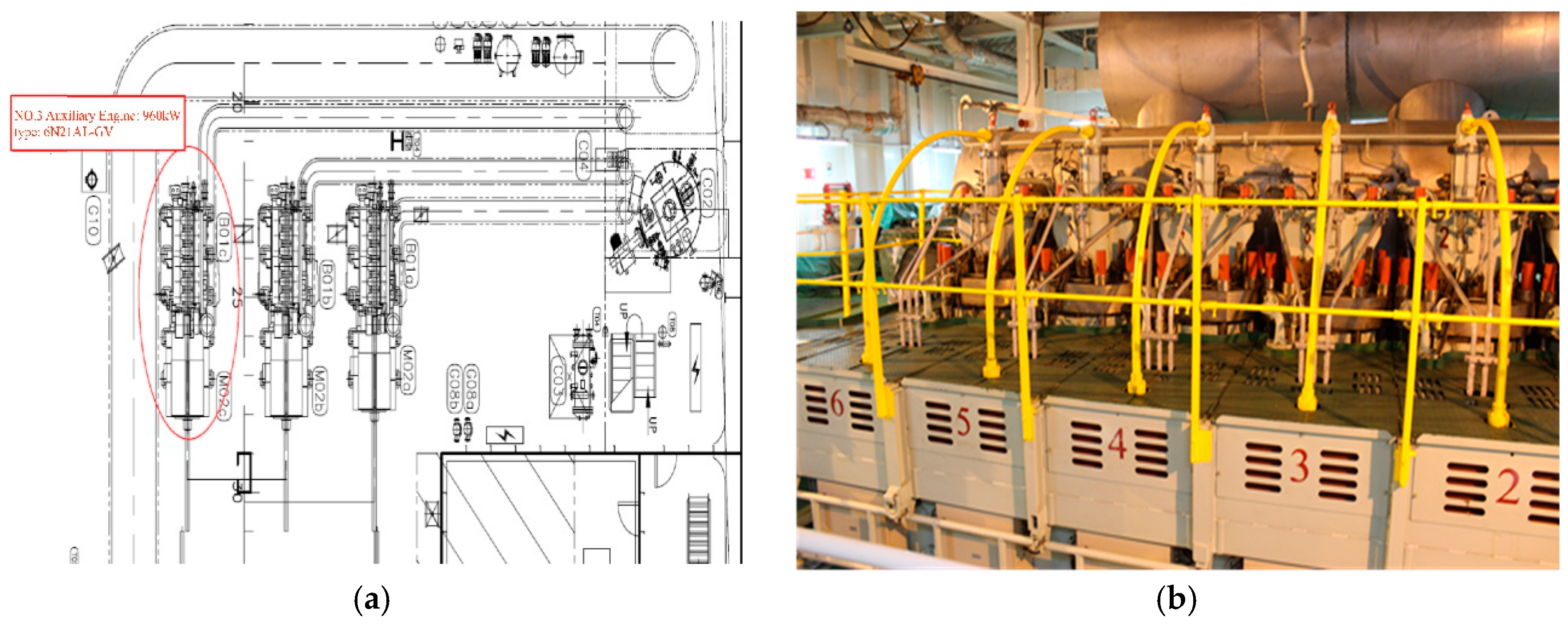
The ‘COSCO Tengfei’ has three diesel generators that are produced by YANMAR (Osaka, Japan), of which two are 1020 kW 6N21AL-GV diesel generators and one is 960 kW 6N21AL-UV diesel generator. Upon ship arrival or departure, two 1020 kW generators are used to provide ship power; while, during normal sailing conditions, only one 1020 kW diesel generator is operated.
Figure 4 shows the configuration of the three diesel generators and the schematic of the 1020 kW diesel generator.
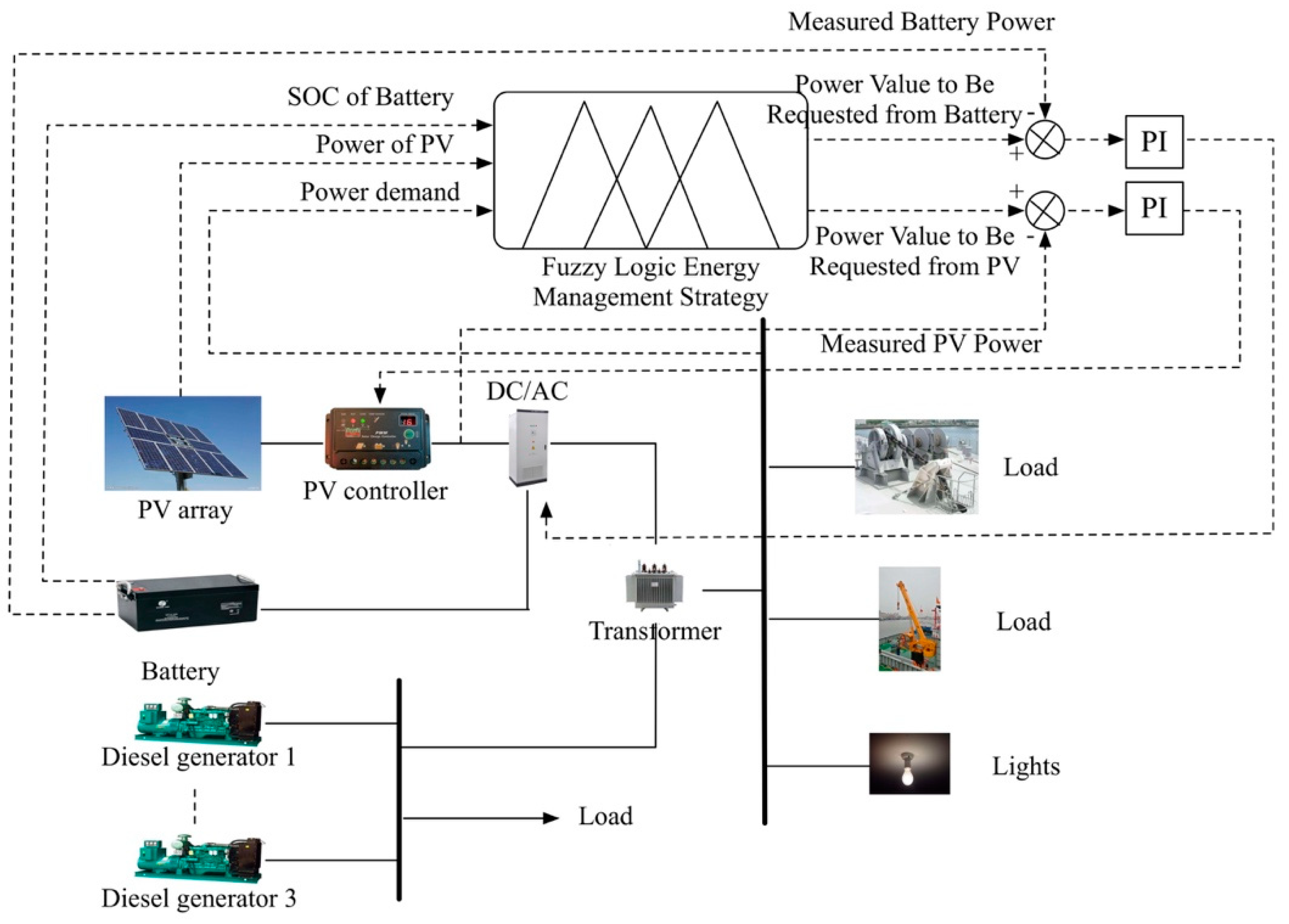
The energy management system monitors the status of the power grid in real time, and optimizes the output power for each power source by comprehensively considering the real-time load demand, the power generation of the solar energy system, and the SOC of the battery packs. In the stand-alone mode, the solar panel and battery only supply power to the lighting system, so the load demand is relatively stable and the control strategy is relatively simple. Hence, in this paper, we mainly focus on the energy management strategy in the grid-tied mode.
3. Fuzzy Logic-Based Energy Management Rules
Under normal sailing conditions, the load of the ship and the power that is generated by the solar photovoltaic system are both uncertain and fuzzy due to the uncertainty and time-varying nature of navigation environment. Hence, in the fuzzy logic energy management strategy, the real-time load demand of the ship, the output power of solar energy, and the SOC of the battery are taken as input variables. The input variables are fuzzified, and then the fuzzy rules and logic functions are used for calculation. After anti-fuzzy conversion, the actual reference output power of the solar energy and the storage battery can be obtained. Through the PI controller, the real-time power output of the battery and the solar system can be precisely controlled, as shown in
Figure 5.
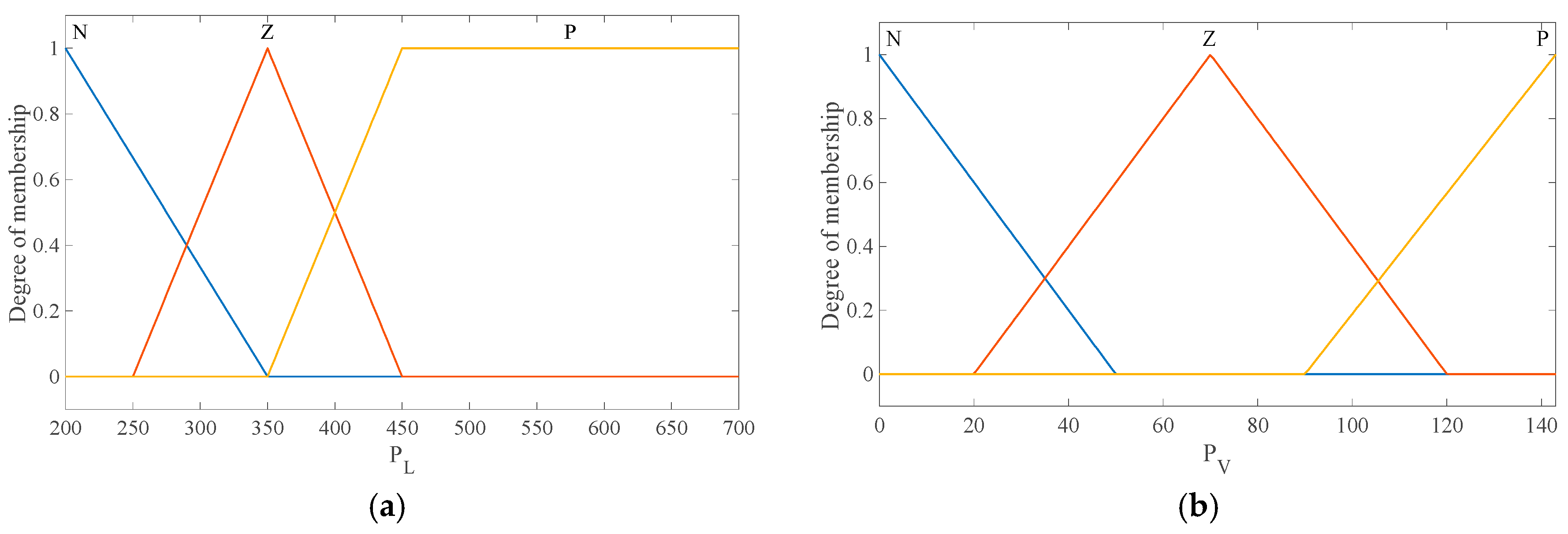
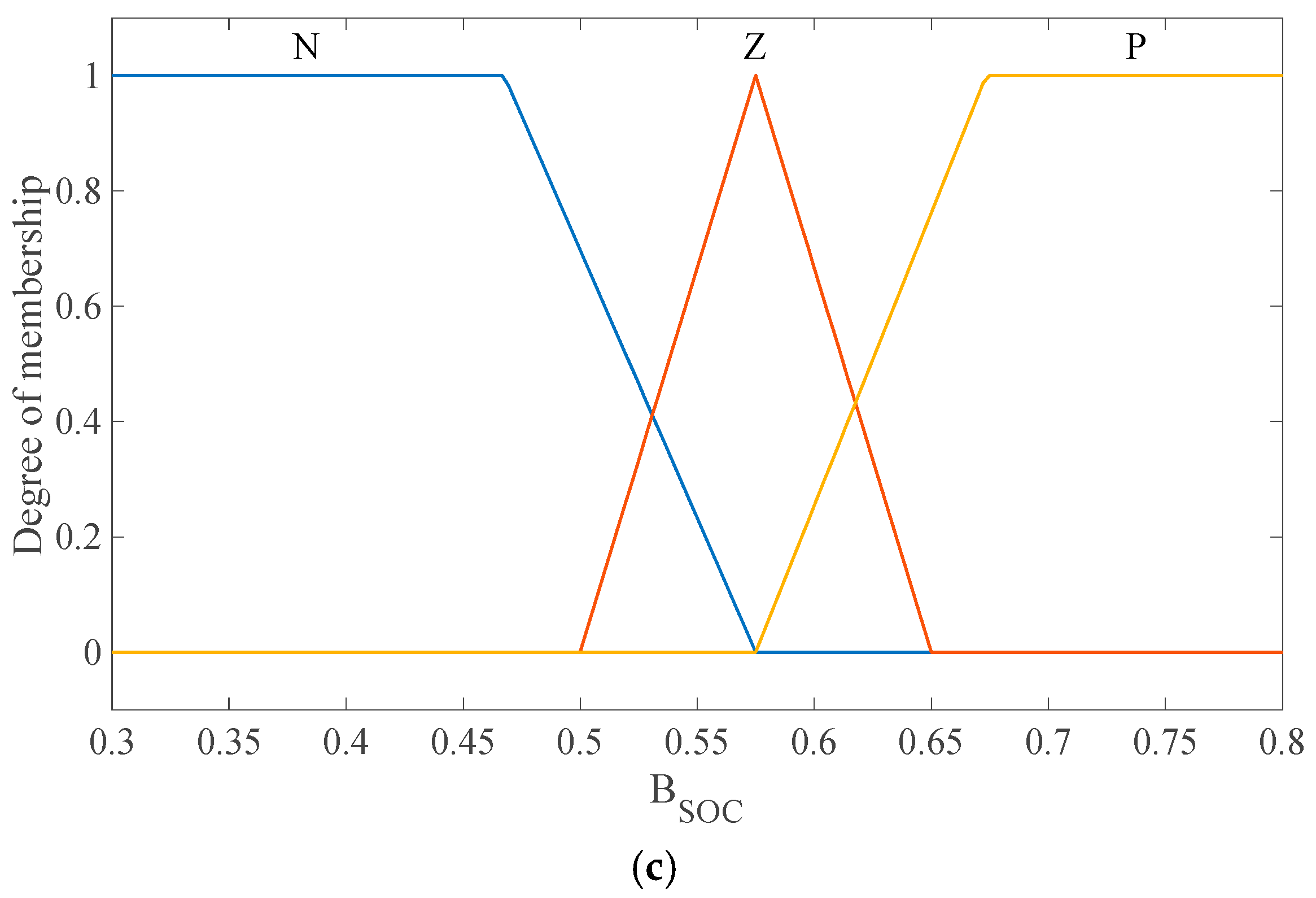
For the ‘COSCO Tengfei’, the ship load demand is between 200 and 700 kW. According to the design of the hybrid power system, the solar power is between 0 and 143 kW and the battery output power is between −150 and 150 kW, where the negative sign indicates a charge state while the positive sign indicates a discharge state. To prevent the battery from being fully charged or discharged, the SOC of the battery is set between 0.3 and 0.8. The fuzzy collection of each variable is determined based on the fuzzy statistical principles, and the corresponding membership functions can be obtained. For the input variables, the ship’s power load demand
PL is divided into three fuzzy sets: large (P), medium (Z), and small (N); the power of solar energy
PV is classified into three fuzzy sets: large (P), medium (Z), and small (N); the SOC of the battery
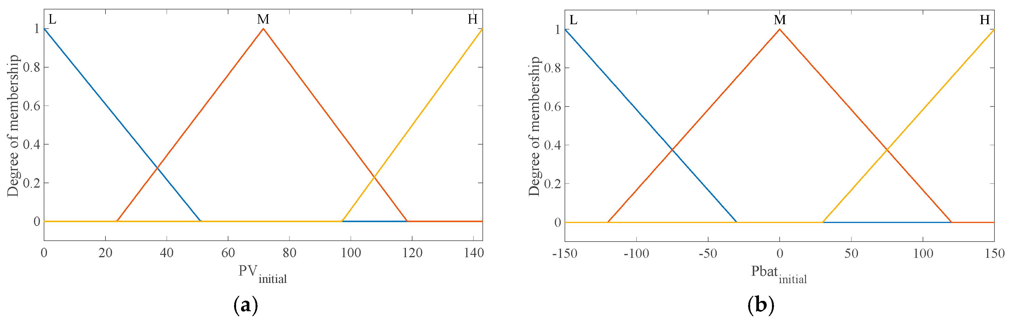
BSOC is fuzzified into three fuzzy sets: large (P), medium (Z), and small (N). The output variables
PVinitial and
Pbatinitial are also fuzzified into three fuzzy sets: high (H), medium (M), and low (L). The input and output membership functions are shown in
Figure 6 and
Figure 7.
For different real-time load requirements, a reasonable fuzzy rule can be established for the power generation of the solar energy system and the current SOC of the battery, to improve the fuel economy of the ship as much as possible. For example, when the ship’s load demand is high, the power that is generated by the renewable energy system is preferred and should be maximized to reduce the power supply of diesel generators; when the ship’s load demand is low, the efficiency of diesel generators should be considered. Under a light load, the specific fuel consumption for diesel generators may increase, so the power of renewable energy system should be injected to the power grid as far as possible. In this case, the output power of the renewable energy system needs to be controlled within a reasonable range. Based on the above principles, a total of 27 fuzzy rules are established and are described in fuzzy language, as follows:
1. If ( is N), ( is N) and ( is N) then ( is L) and ( is L)
2. If ( is N), is N) and ( is Z) then ( is L) and ( is M)
3. If ( is N), ( is N) and ( is P) then ( is L) and ( is M)
4. If ( is N), ( is Z) and ( is N) then ( is M) and (
24. If ( is P), ( is Z) and ( is P) then ( is M) and ( is H)
25. If ( is P), ( is P) and ( is N) then ( is H) and ( is L)
26. If ( is P), ( is P) and ( is Z) then ( is H) and ( is M)
27. If ( is P), ( is P) and ( is P) then ( is H) and ( is H)
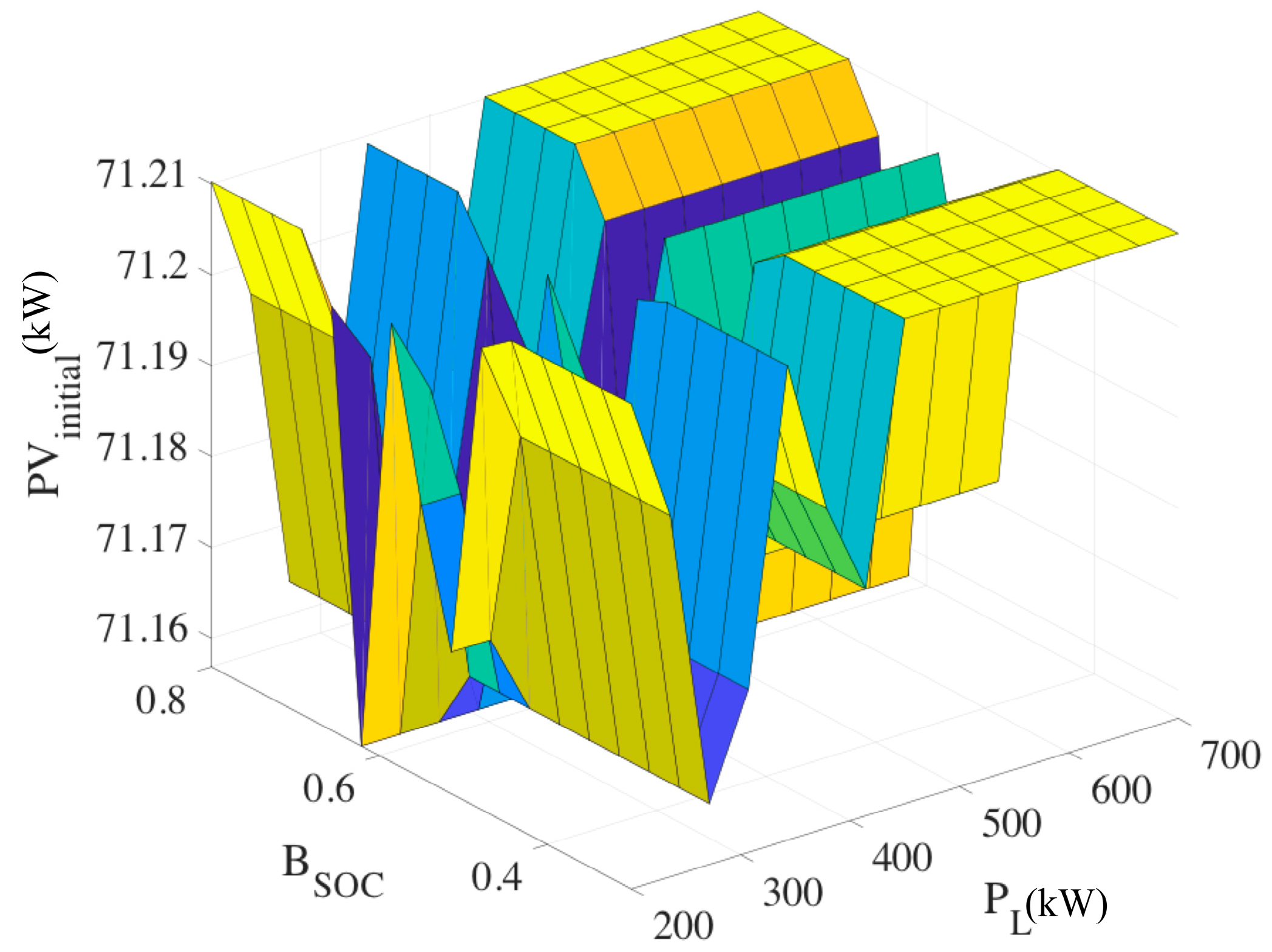
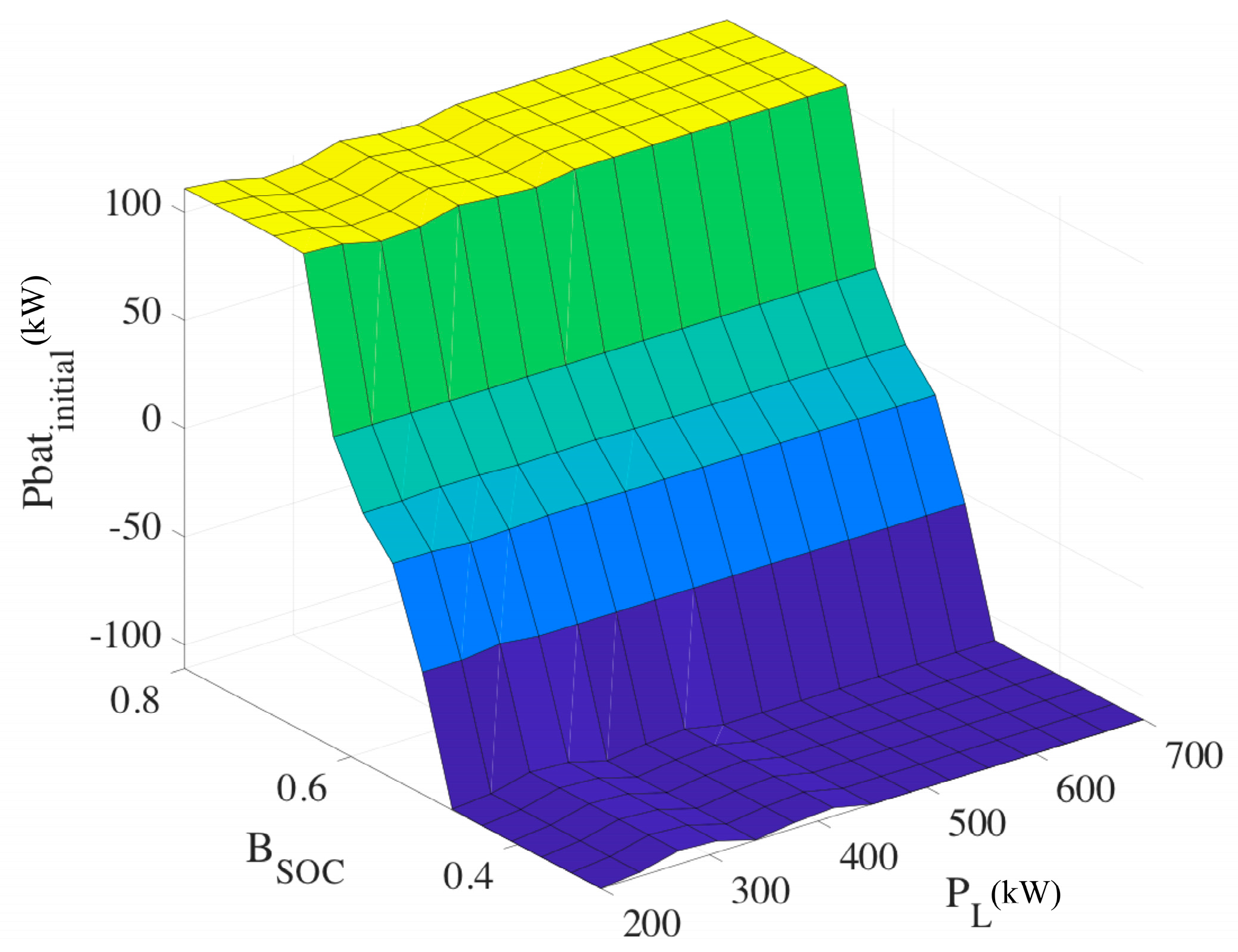
The fuzzy reasoning system can generate the output surfaces of solar power
PVinitial and battery power
Pbatinitial, as shown in
Figure 8 and
Figure 9.
After calculation by the fuzzy logic module, the output values of solar power
PVinitial and battery power
Pbatinitial are only preliminary reference values, because the output power of solar energy
PVinitial may be greater than the actual power that is generated by solar system, which does not satisfy the basic logical relationship. After logical judgment,
PVinitial and
Pbatinitial finally lead to the reference output powers of the solar energy
PVref and the battery
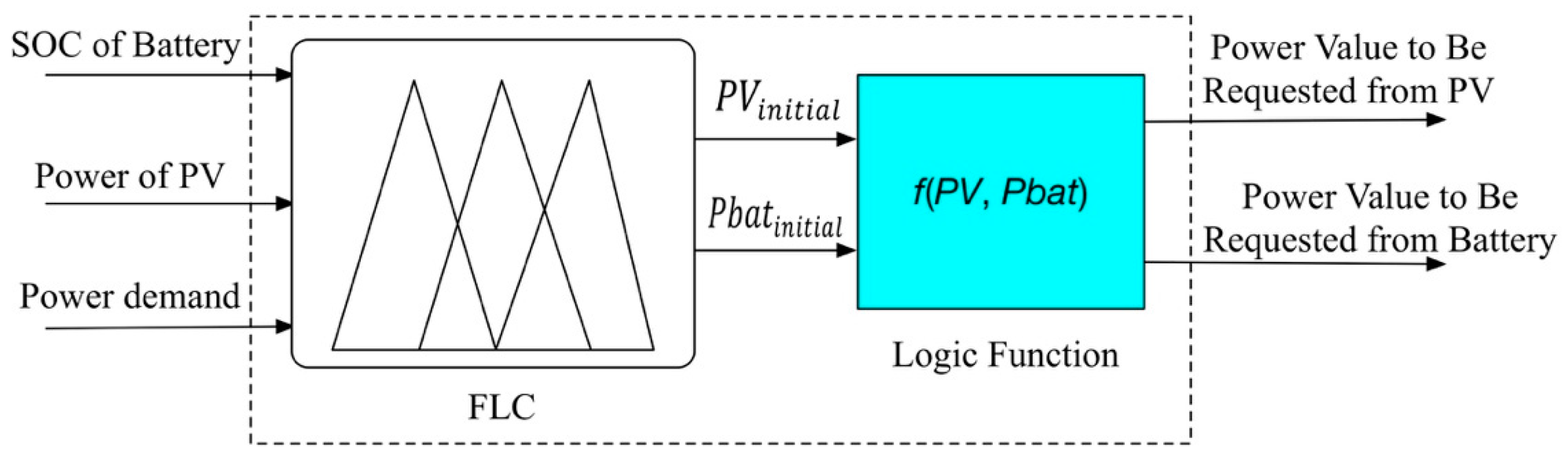
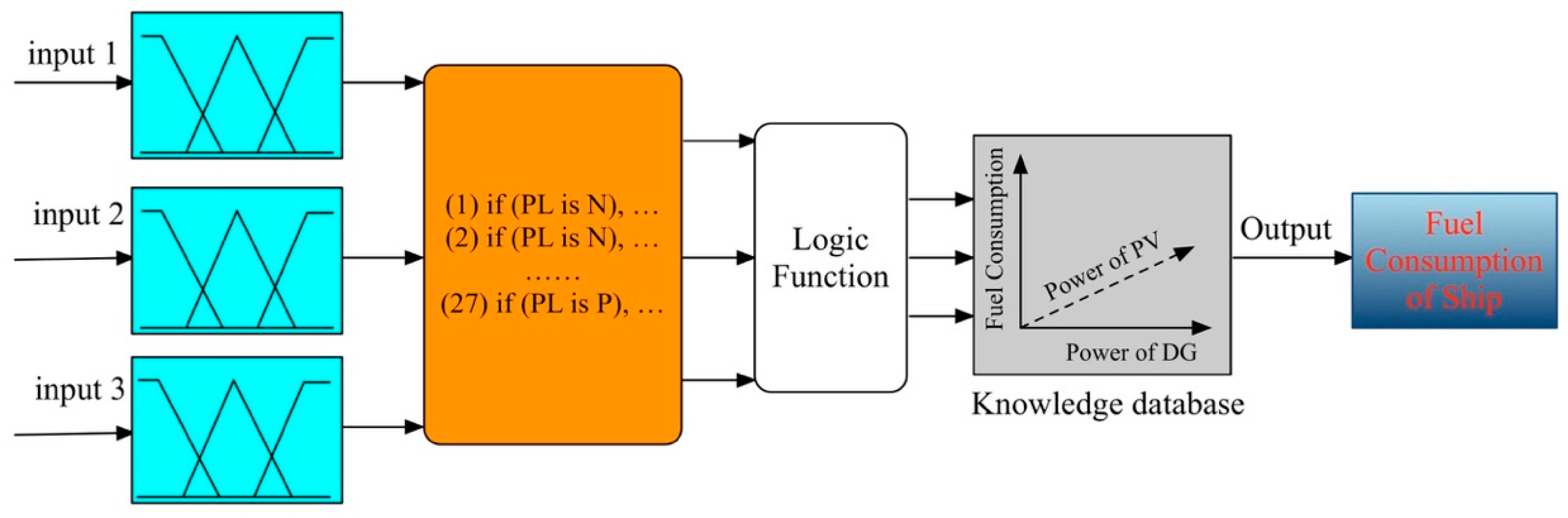
Pbatref respectively. The energy management strategy structure that is based on fuzzy logic is shown in
Figure 10, and the logic function satisfies the following relationship:
(1) When
PVinitial ≤ ,
Then, the output power of the diesel is:
(2) When
PVinitial >
,
Then, the output power of the diesel is:
4. Results Analysis
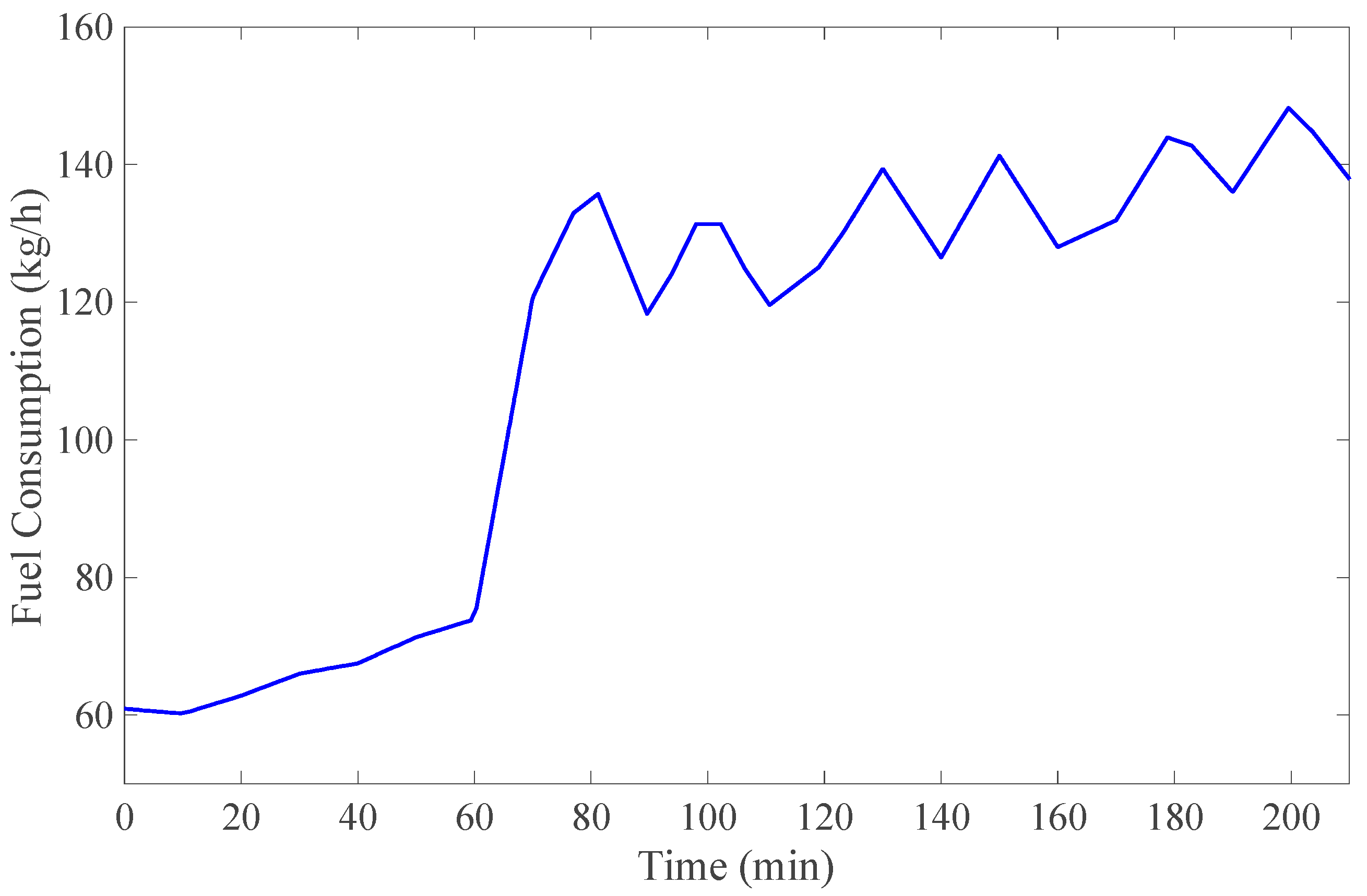
Since the solar hybrid system that is installed on the ship is modified based on the ship’s original power system, it is necessary to test the system afterward. The system test mainly includes solar energy grid-tide and stand-alone mode control test, safety protection test of photovoltaic power distribution system, as well as management and safety control test of lithium-ion battery storage system. After the system integration and test is passed, the ship can then be put into operation. After the installation and debugging of the solar hybrid power system on the ‘COSCO Tengfei’ in March 2016, we collected the data of power load, diesel generation power, solar system output power, and battery output power in the grid-tied mode. The ship’s electrical loads mainly have devices, such as cabin lighting system, steering gear, telecommunication equipment, and anchoring machines. The test was 210 min, and the ship’s driving distance was about 60 km. During the test, the weather conditions were good, and there were no significant winds or waves. During data acquisition, the battery’s initial SOC was set as 60%. The load demand of the ship, the output power of the diesel generator, the output power of the solar system, and the corresponding hourly fuel consumption are shown in
Figure 11 and
Figure 12.
To verify the effectiveness of the proposed fuzzy logic-based energy management strategy, a simulation model that is based on MATLAB/Simulink (R2017a, MathWorks, Natick, MA, USA) is established, as shown in
Figure 13. The solar power, ship load demand, and battery SOC are considered as input variables. Through the establishment of fuzzy rules and logic functions, the optimal output powers of the solar system, diesel generator and battery can be obtained. Afterwards, the ship fuel consumption can be derived by the learning of knowledge base.
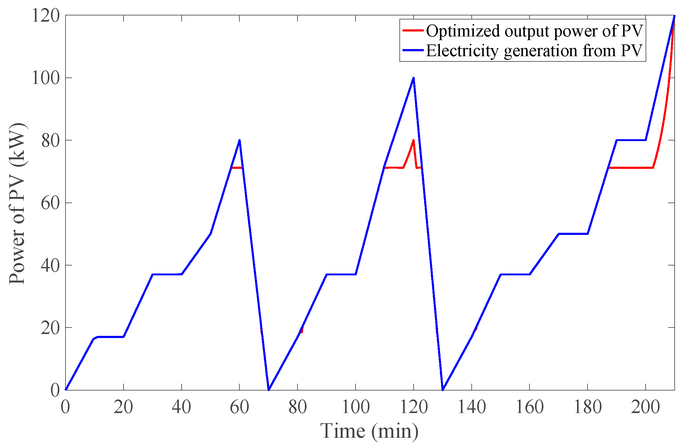
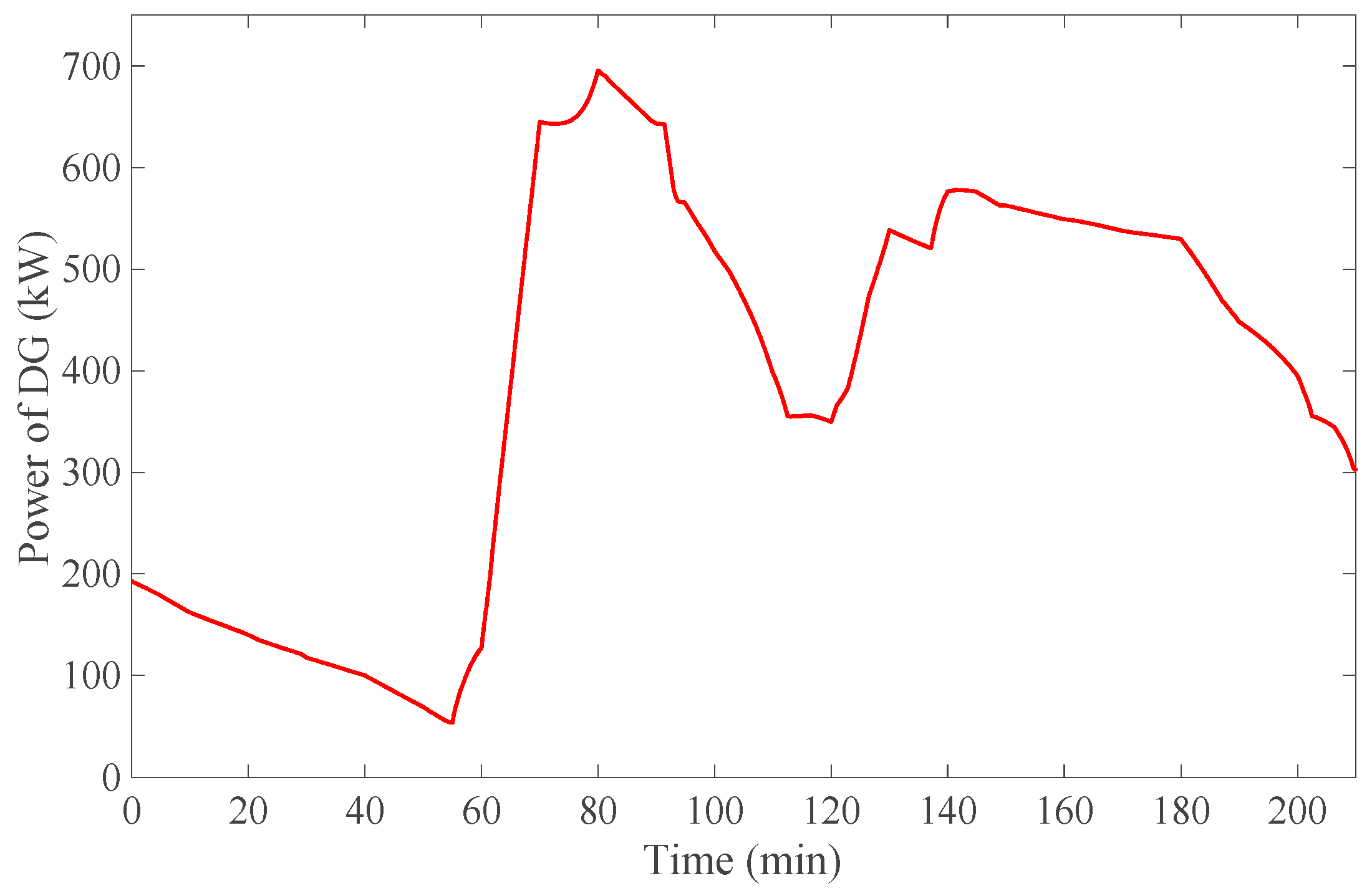
Figure 14,
Figure 15,
Figure 16 and
Figure 17 show the simulation and calculation results based on the fuzzy logic energy management strategy.
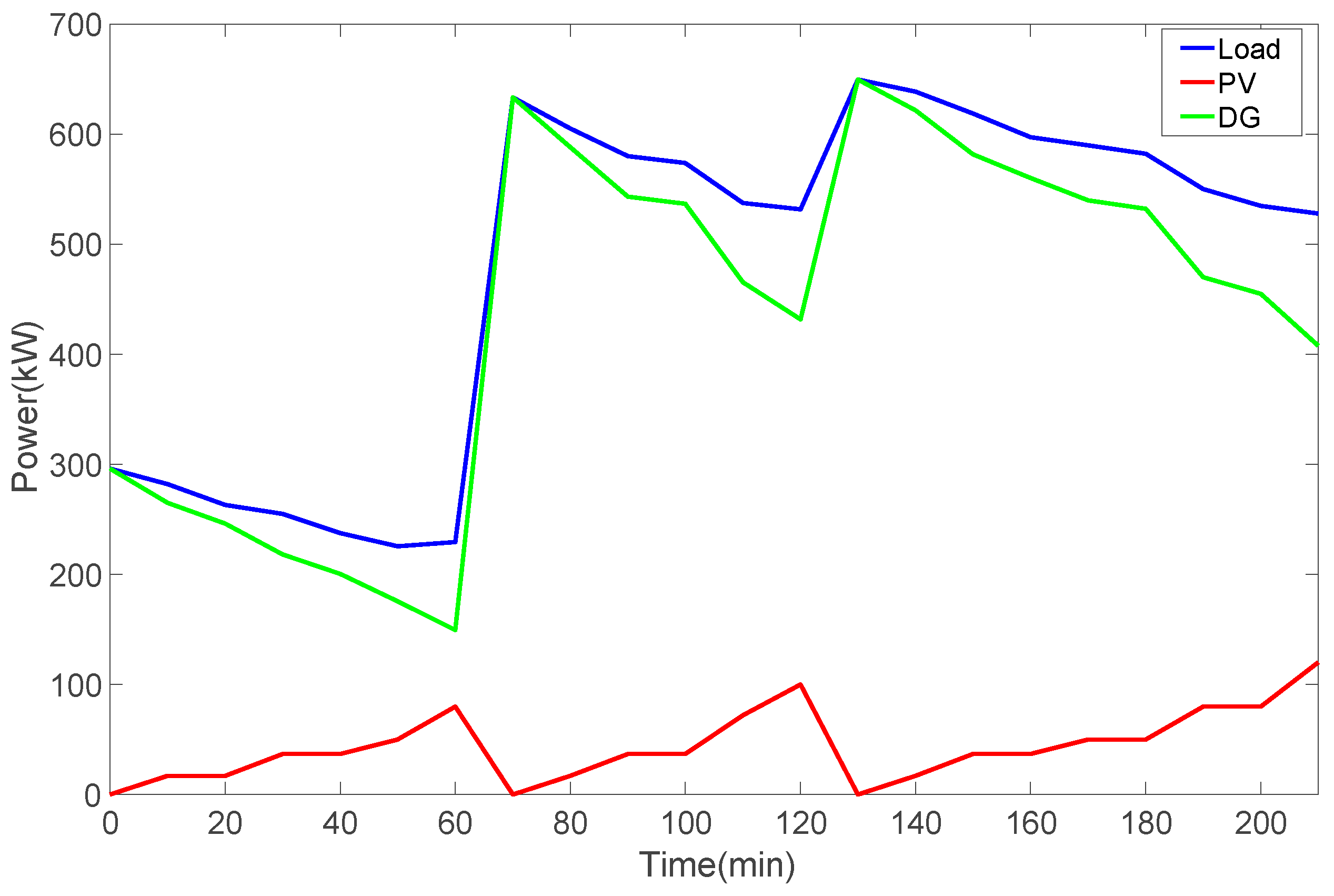
From
Figure 14, it can be found that the power generated by the solar system can be fully utilized by adopting the fuzzy logic-based energy management strategy, except at the three peak power stages of the solar system. The reason is that when the solar power is at the peak value, the load demand of the ship is coincidentally at the lowest stage. At this moment, enhancing the renewable energy injection to the grid can cause a lower efficiency of the diesel generator and increase the specific fuel consumption, thus increasing the overall fuel consumption of the ship. Instead, the remaining solar energy can be used to charge the battery.
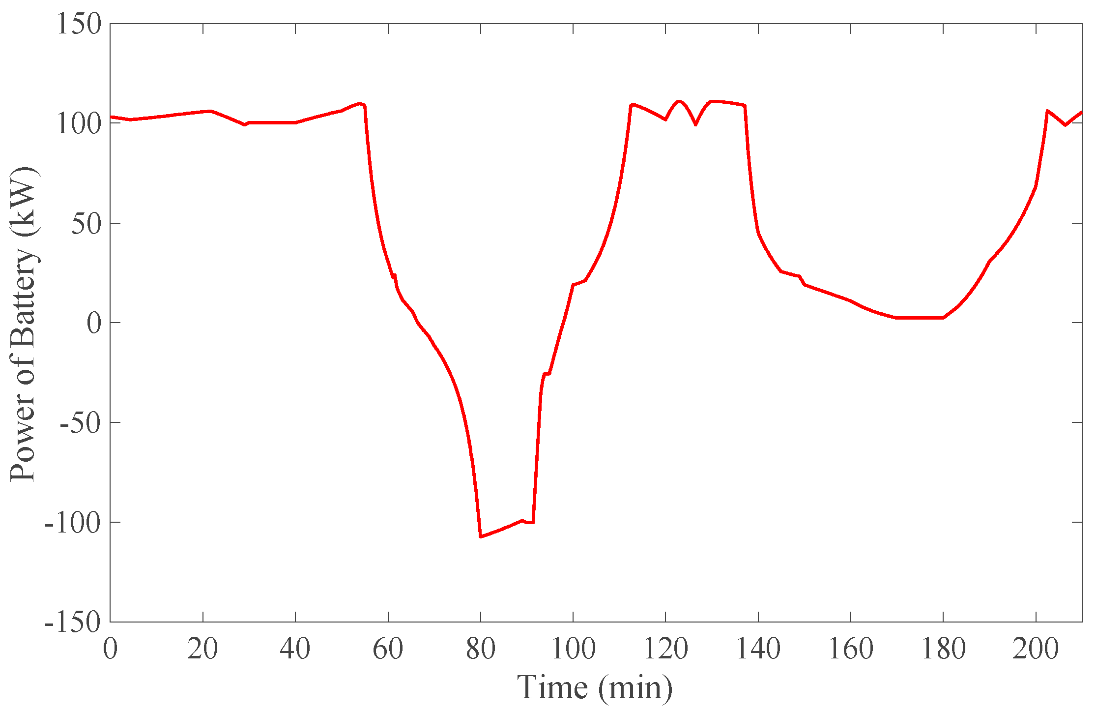
Before optimization, the output power of the diesel generator is slightly higher when the ship’s load demand is low and slightly lower when the ship’s load is high. When the system is controlled by the fuzzy logic control strategy, the output power of the diesel generator generally follows the load variation, and the diesel generators can work within a narrower range with smaller specific fuel consumption on the premise of satisfying the load demand of the entire ship. Meanwhile, the battery system can play dual roles of providing auxiliary energy when the solar power is insufficient and storing solar energy when the grid power is surplus.
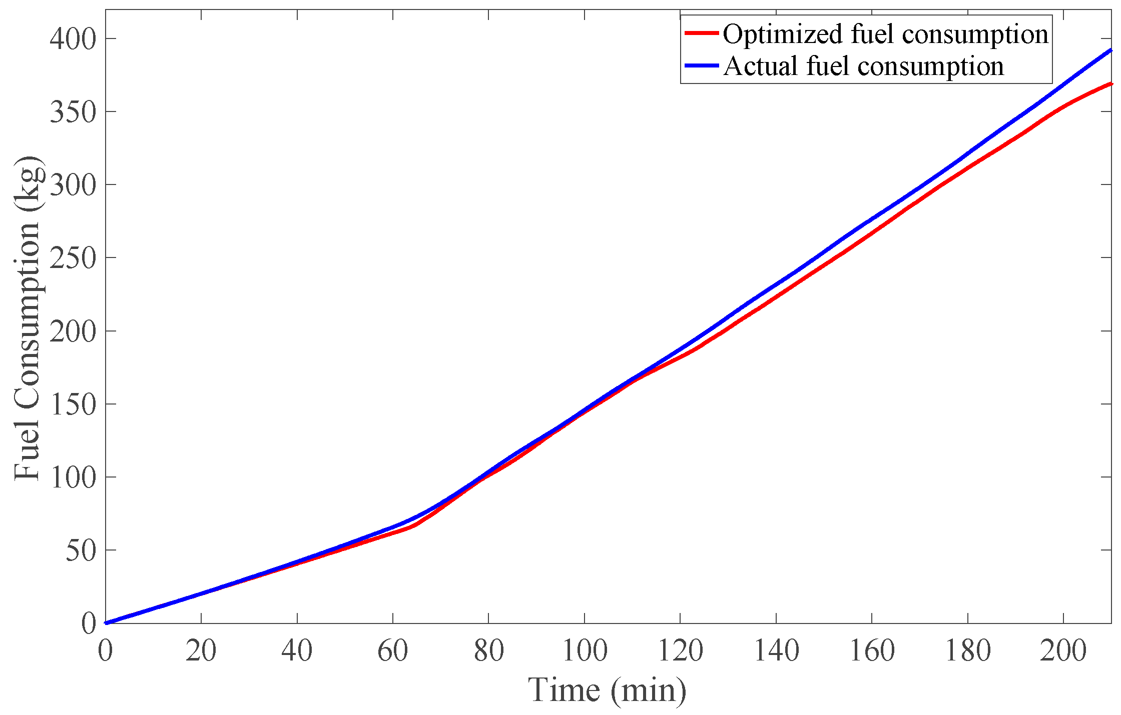
Figure 17 shows the fuel consumption measured by the real ship and the fuel consumption after the adoption of the fuzzy logic energy management strategy. Within 210 min, the actual fuel consumption of the ship is 392.45 kg, which can be calculated by the area within the fuel consumption curve in
Figure 12. By contrast, after the adoption of the fuzzy logic control strategy, the simulation shows that the ship’s fuel consumption is reduced to 369.27 kg, which is approximately 6% less than the actual fuel consumption.
5. Economic Evaluation
The cost of modifying a ship power system into a solar hybrid system includes hardware equipment acquisition cost and software acquisition cost, as shown in
Table 2.
During normal navigation, the electrical load of the ship is around 600 kW. When the solar hybrid system that is designed in this paper is not used, the fuel consumption and CO
2 emission of the diesel generators in one year are:
where
q is the fuel consumption per unit time (kg/h), and the fuel consumption per unit time is 137.9 kg/h when the generator power is 600 kW;
T is the ship navigation time (day), with a value of 365; and,
β is the carbon emission coefficient, with a value of 3.175.
Therefore, without solar energy, the fuel consumption and CO
2 emission of a ship’s generators for one year are:
When the ship is powered by the solar energy, the solar photovoltaic system can work for 292 days per year based on the crew’s record of weather information on the route of ‘COSCO Tengfei’. The ship generator set can always save some energy, but the saving amount is different when the solar system is connected with different loads. According to the experimental data, when the electrical load is 600 kW and the solar energy output accounts for 22.7% of the load power, the optimal fuel consumption of 115.7 kg/h can be obtained.
Assuming that the effective sunlight is six hours per day, in an ideal case, the ship can save fuel consumption and reduce CO
2 emission as:
Then, the annual energy-saving fuel cost is $32,600. Hence, the cost can be recovered in 25.7 years without considering the equipment maintenance cost. Since the output power of the solar energy system is affected by weather conditions, it may greatly vary during navigation. According to the analysis above, an optimized energy management strategy, such as fuzzy logic control, can improve the overall performance of the hybrid system, reduce the fuel consumption, and further shorten the investment recovery period.
6. Conclusions
In summary, an energy management strategy based on the fuzzy logic control is proposed, considering the stochasticity and fuzziness of the ship power load demand and solar power generation. By comparing the real ship experimental data and the simulation results, the following conclusions can be drawn:
(1) For the hybrid systems of solar/diesel generators, the energy management strategy based on the fuzzy logic control can optimize the dynamic characteristics of each power source, and the output powers of all power sources can be well distributed, thus improving the fuel economy of the ship.
(2) After the adoption of the proposed energy management strategy, the overall performance of the solar hybrid system can be improved, with reduced fuel consumption and CO2 emission, and therefore, the investment recovery period can be shortened.


