Article

Performance Analysis on the Optimum Control of a Calorimeter with a Heat Recovery Unit for a Heat Pump

by
Kofi Owura Amoabeng
1 and
Jong Min Choi
2,*
1
Mechanical Engineering Graduate School, Hanbat National University, Daejeon 34158, Korea
2
Mechanical Engineering Department, Hanbat National University, Daejeon 34158, Korea
*
Author to whom correspondence should be addressed.
Energies 2018, 11(9), 2210; https://doi.org/10.3390/en11092210
Submission received: 8 August 2018 / Revised: 17 August 2018 / Accepted: 23 August 2018 / Published: 23 August 2018
(This article belongs to the Section D: Energy Storage and Application)

Abstract

:
Heat pumps are used in many applications, both in households and industries, for space air conditioning and hot water provision. The calorimeter is the equipment used in testing the heat pump system to obtain performance data. In the conventional testing mode and under standard conditions, the calorimeter utilizes a lot of energy through refrigeration and heating systems. In this study, a newly developed calorimeter with a heat recovery unit was used to test the performance of a water-to-water heat pump system. The aim was to minimize the rate of energy used in the conventional calorimeter. Two heat recovery control methods were adopted. In the control (1), the heat recovery unit was used to control the inlet water temperature setpoint for the heat pump indoor heat exchanger, whereas in control (2), the heat recovery unit was used to control the inlet water temperature setpoint for the heat pump outdoor heat exchanger. Tests were executed by varying the operating mode and test conditions. For the heating operating mode, the inlet water setpoint temperatures for the indoor and outdoor heat pump heat exchangers were 40 °C and 5 °C, respectively, whereas for the cooling mode, the inlet water setpoint temperatures for the outdoor and indoor heat pump heat exchangers were 25 °C and 12 °C, respectively. The analyses of the experimental results revealed that the energy saving of the calorimeter with heat recovery was about 71% in cooling mode and 73% in heating mode compared to the conventional calorimeter. Also, the energy consumption of the proposed calorimeter was analyzed based on the control methods. In heating mode, the calorimeter performance was enhanced when the control (2) strategy was used because the energy saving was about 8 to 13% compared to control (1). However, in the cooling mode test, it was the control (1) method that resulted in energy savings of about 6.4 to 21% compared to the control (2) method.

1. Introduction

Heat pumps are used in many applications, both in households and industries, for space air conditioning and hot water provision [1]. This is due to the economic benefit of using heat pumps to extract heat from alternate sources, namely air, water, and the ground [2]. Globally, energy saving potential has become a very important matter to obtain rational development and also reduce carbon emissions [3]. Therefore, it is necessary to enhance the heat pump system performance in order to make such pumps more energy efficient. Some of the techniques used to improve the heat pump system performance have been used in research [4,5,6,7,8,9]. Vahid et al. [10] published a concise review of different control strategies of saving energy in heat pump systems. Elraheim et al. [11] assessed the performance of a domestic air conditioner that used R410A under different indoor operating characteristics. Shi et al. [12] also investigated a heat pump system with an economized vapour injection using R32 with the control of evaporating temperature. Gao et al. [13] proposed a control strategy for an integrated heat pump system with a small capacity. Their results showed 9.6% in energy savings for a normal day in spring and 3.0% for a normal day in summer. Madani et al. [14] also conducted a study on a heat pump with a ground source using on/off control methods and deduced that the degree-minute control strategy utilized the lowest amount of energy.
However, heat pump manufacturers and researchers often make use of a performance test facility known as the calorimeter to measure the heat pump system performance using test standards [15,16,17,18]. Basically, the calorimeter for heat pump systems has two sections: an indoor flow loop section or indoor chamber and an outdoor flow loop section or outdoor chamber. The indoor unit and outdoor unit for the heat pump system are connected to the indoor and outdoor section of the calorimeter, respectively. Either section can serve as a heat source or sink according to the operating mode of the heat pump. Conventionally, each section of the calorimeter is independently controlled using a heating unit and a refrigeration unit since there is no connection between the indoor section and outdoor section.
Among researchers that have used calorimeters to investigate heat pump system performance, Wang et al. [19] used a calorimeter to measure the heating performance of a CO2 heat pump system in an electric vehicle, as shown in Figure 1. The variation in operating conditions such as outdoor air temperature, indoor temperature, indoor air flow rate, compressor speed, and expansion valve opening, were considered for the experiment. The cooling unit, heater, and humidifier were used to control the air conditions in each chamber. In a study on the performance of a multi-functional heat pump with a solar simulator, Jie et al. [20] also used an air-enthalpy type calorimeter to measure the heating capacity of an indoor air heat exchanger. Ho-Seong Lee et al. [21] conducted a research to investigate the performance of a heat pump unit with R774 for electric vehicles using waste heat from the stack coolant as the heat source in a psychrometric calorimeter.
Park et al. [22] also used a psychrometric calorimeter to investigate the performance of a heat pump unit with evaporation pressure control. The experimental conditions of temperature and humidity in both indoor and outdoor chambers were based on the Korean Standard (KS C9306) [23]. Using a calorimeter measurement technique, Carrington and Liu [24] determined the impact of evaporator air flow on a heat pump dehumidifier drier. Moreover, to compare the performance characteristics of single-stage and cascade heat pumps for space heating and hot water provision, Jung et al. [25] also used the air-enthalpy type calorimeter to measure the indoor unit heating performance. In their experimental setup, the heat pump outdoor unit was installed in a psychrometric chamber, whereas the indoor unit was installed in separate air handling unit to control the temperature and humidity. Changhyun Baek et al. [26] examined control strategies for testing the cooling performance of a CO2 heat pump in a psychrometric calorimeter consisting of indoor and outdoor chambers. Fan et al. [27] proposed a multi-unit heat pump for controlling temperature and humidity at the same time. The performance of the heat pump cycle was investigated with a psychrometric calorimeter. Kim and Bullard [28] performed an experiment to show the shut-down and start-up characteristics of a residential split system R-410A air conditioner with a capillary tube using a psychrometric calorimeter.
Although heat pump calorimeters have been used in research, the focus has been on the energy performance evaluation of the heat pump unit. However, research conducted to assess the calorimeter performance characteristics is significant for identifying the ways to reduce the energy consumption of the calorimeter. Amoabeng et al. [29] studied the energy analysis of the conventional calorimeter that was used in testing the performance of a water-to-water heat pump system. The test results of their investigation showed that the energy consumption of the conventional calorimeter was much higher compared to the energy consumption of the heat pump system under standard operating conditions. Therefore, it is necessary to adopt strategies to reduce the energy consumption of the conventional calorimeter. Nonetheless, research on innovative ways to improve the energy efficiency of calorimeters is infrequent in literature. A flow calorimeter was developed by Schroder et al. [30], which was able to get rid of the hypothesis used in determining the specific heat capacity of geothermal water flow. Rodolfo et al. [31] also used a predictor-based control technique to enhance the performance of a compressor calorimeter.
In this study, a new calorimeter was designed to investigate the heat pump system performance. In order to save energy consumption of the conventional calorimeter, a heat recovery unit was adopted in this new calorimeter. To analyze the energy savings of the new system, two control methods for the heat recovery unit were used during the investigation period. This was conducted to examine the appropriate control method to enhance the performance of the newly developed calorimeter.

2. Experimental Rig and Test Procedure

2.1. Description of Test Rig

Figure 2 shows the test rig of the calorimeter with a heat recovery unit designed to measure the water-to-water heat pump performance. The setup consists of the calorimeter and heat pump connected together using flow loops. The heat pump unit is a test simulator which enables the capacity and heat pump COP to be varied individually.
It is made up of two heat exchangers and each heat exchanger has a separate pump and temperature bath to vary the temperature and flow rate based on the capacity and COP of the heat pump, as seen in Figure 2. Each heat exchanger (HX, hereafter) can operate as an indoor unit or outdoor unit according to the heat pump mode of operation. The calorimeter consists of two flow loops; the indoor loop and outdoor loop. The indoor unit and outdoor unit of the heat pump are connected to the indoor flow loop and outdoor flow loop of the calorimeter, respectively. The secondary fluid that circulates through the indoor and outdoor flow loops is water and ethylene glycol solution with a concentration of 40%. Each calorimeter flow loop is equipped with a water temperature bath (WTB, hereafter), refrigeration system with a constant speed compressor, and an electric heating system. The refrigeration and heating systems are used to maintain the secondary fluid temperature inside the WTB based on test standards [16,18]. Also, on each calorimeter flow loop, there is a flow meter and a pump. The flow meter measures the secondary fluid volumetric flow rate, whereas the pump circulates the secondary fluid through each flow loop.
The heat recovery (HR, hereafter) unit connects the two flow loops of the calorimeter to allow the transfer of heat from one calorimeter flow loop to the other. The calorimeter indoor flow loop also has two needle valves to control the quantity of heat flow through the HR unit from one section of the flow loop to the other. The conventional calorimeter for the water-to-water heat pump system does not include a heat recovery unit when compared to the setup proposed in this study.
Resistance thermal detectors (RTDs) with a ±0.1 °C reading scale accuracy are the instruments used to measure the flow temperatures in the test rig. Magnetic flow meters with ±0.1% of full scale are used to measure the secondary fluid flow rate. The temperatures in the experimental test rig are observed using ASHRAE standard 41.1 [32]. The measured flow temperatures and volumetric flow rates at inlets and outlets of the heat pump indoor HX and outdoor HX are used to calculate the capacities of heat pump according to Equation (1), with a calculation uncertainty of ±5% based on reference [17].
Q h p = V f · ρ f · c p f · Δ T f
The refrigeration unit and electric heater on each flow loop are used to determine the energy consumption of the calorimeter. They are measured with a Yokogawa power meter that has a reading scale accuracy of ±0.1%. The various component specifications and sensors in the experimental test rig are shown in Table 1.

2.2. Test Procedure

Two heat recovery control methods for the new calorimeter setup were proposed to measure the water-to-water heat pump system performance. The energy consumption of the calorimeter according to the control methods was investigated. Tests were executed in varying operating modes with changes in test conditions, such as the capacity and COP of the heat pump being tested. The water flow rates were the same for both indoor (ID, hereafter) and outdoor (OD, hereafter) calorimeter flow loops based on the capacity of the heat pump unit being tested.
To begin the experiment, standard test conditions were set based on the operating mode of the heat pump unit being tested. The standard inlet water temperature (IWT, hereafter) setpoints were 40 °C and 5 °C for the indoor and outdoor heat exchangers of the heat pump in heating mode, respectively, whereas in the cooling mode, the IWT setpoints for the ID and OD heat exchangers of the heat pump were 12 °C and 25 °C, respectively, based on test standards [16,18]. The heat recovery control method labelled as control (1) was used to control the inlet water temperature setpoint for the indoor heat pump HX at the indoor side flow loop, with values of 12 °C in cooling mode and 40 °C in heating mode. Similarly, the HR control method, also labelled as control (2), was used to control the IWT setpoint for the outdoor heat pump HX at the outdoor side flow loop. In this case, the temperature was set to 25 °C in cooling mode and 5 °C in heating mode. The test conditions used to perform measurements in the test rig are shown in Table 2.
In the heating mode experiment, water from the water temperature bath located at the calorimeter OD loop and ID loop drifted through the OD and ID heat pump heat exchangers, respectively. The OD heat pump HX absorbed heat from the water, whereas heat was discharged to the water that flowed through the ID heat pump HX. As such, the exit temperature of water (EWT, hereafter) at the outlet of the OD heat pump HX decreased, whereas the EWT increased at the outlet of the ID heat pump HX. The low water temperature at the exit from the OD heat pump HX and water at a high temperature from the ID heat pump HX exit then proceeded through the HR unit. Heat transfer then occurred in the HR unit from the water at the ID flow loop to the water at the OD flow loop. In the control (1) method, the IWT setpoint for the ID heat pump HX was controlled by altering the needle valve opening at the inlet of the HR unit. However, the inlet water temperature for the outdoor HX was controlled by using the refrigeration system and electric heating device in the OD flow loop. In the control (2) method, the needle valve was used to maintain the IWT condition for the outdoor heat pump heat exchanger, while the refrigeration system and the electric heater at the indoor flow loop were operated to set up the IWT for the ID heat pump HX.
In a similar way, for the heat pump test in cooling mode, the water from the water temperature bath at the OD and ID flow loops of the calorimeter circulated through the outdoor and indoor heat pump heat exchangers, respectively. The ID heat pump HX absorbed heat in the water, whereas heat was discharged to the water from the OD heat pump HX. As such, the exit water temperature at the outlet of the heat pump indoor HX decreased, whereas the EWT increased at the outlet of the OD heat pump HX. The low exit water temperature from the ID heat pump HX and high exit water temperature from the OD heat pump HX exit then drifted through the heat recovery unit. Heat transfer then took place in the HR unit from the water at the OD flow loop to the water at the ID flow loop. In control (1), the needle valve at the inlet of the HR unit was adjusted to set up an IWT of 12 °C for the ID heat pump HX. The IWT setpoint value of 25 °C for the outdoor heat pump HX was controlled by the electric heater and refrigeration system installed in the calorimeter OD flow loop. In control (2), the heat transfer amount between the indoor water flow loop and outdoor water flow loop in the HR unit was controlled by regulating the needle valve to set up the IWT for the OD heat pump HX. The IWT of the indoor heat pump HX was adjusted by operating the refrigeration system and electric heater located at the indoor water flow loop.
The water temperatures and flow rates in the test rig were considered to be steady when the values were ±0.1 °C and ±0.1 L per minute, respectively. At steady state conditions, measured performance test data for the calorimeter and heat pump unit were recorded for 30 min with a second interval using a data acquisition (DAQ) system. The measured water temperature and volumetric flow rate values at relevant locations in the test rig were used to assess the capacities of the heat pump, as well as the COP. The required data for the refrigerators and electric heaters in both calorimeter flow loops were measured with a power measuring instrument.

3. Test Results and Analysis

3.1. Calorimeter Control Performance for Heating Operating Mode

Figure 3 and Figure 4 show the calorimeter performance based on the heating capacity in control (1) in terms of flow loop temperature and energy consumption, respectively. As shown in Figure 3, for both indoor and outdoor side flow loops, the water temperature at the inlet to the heat recovery unit remained the same as the heating capacity of the heat pump increased because the water flow rate was proportional to the heat pump capacity.
However, the exit water temperature from the outdoor HX decreased, whereas the water exit temperature from the indoor HX increased. As a result, the inlet water temperature to the heat recovery unit from the outdoor flow loop was lower than the IWT setpoint for the outdoor HX, and the inlet water temperature to the HR unit from the indoor flow loop became higher than the IWT setpoint for the indoor heat exchanger.
Therefore, the needle valve at the inlet to the HR unit was regulated to control the quantity of heat transfer from the ID flow loop to OD flow loop such that the inlet water temperature to the indoor heat pump HX was maintained at a setpoint of 40 °C. Moreover, when the heating capacity of the heat pump was increased, the heat exchange rate in the HR unit also increased because the flow rate of water increased. As such, the inlet water temperature to the outdoor refrigerator increased with an increase in heat pump capacity. Also, IWT to the OD refrigerator increased above the water setpoint temperature of 5 °C for the outdoor heat pump HX. Therefore, the calorimeter OD refrigeration unit was operated to extract heat from the secondary fluid in the OD flow loop. The OD loop heater IWT was increased as the heating capacity and flow rate increased. However, the OD heater IWT was below the inlet water setpoint temperature for the outdoor heat pump HX. Therefore the OD heater unit was turned on to maintain the IWT setpoint for the OD heat pump HX. In 
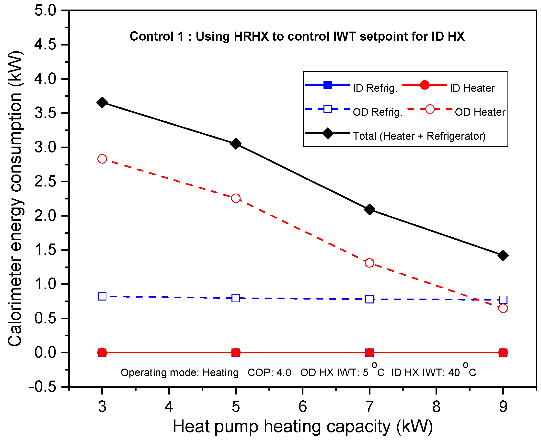
Figure 4, the energy used by the ID heater and ID refrigerator was zero because both units were not operated as the heat recovery unit was used to control the inlet water setpoint temperature for the indoor heat pump HX. The energy utilization rate of the OD refrigerator was relatively uniform as the capacity increased because the refrigerator was operated at a constant speed. Also, the energy utilized by the outdoor heater decreased when the heating capacity was increased because the inlet water temperature to the OD flow loop heater also increased. Hence, the total rate of energy utilized by the calorimeter decreased when the capacity of the heat pump unit being tested was increased. Figure 5 and 
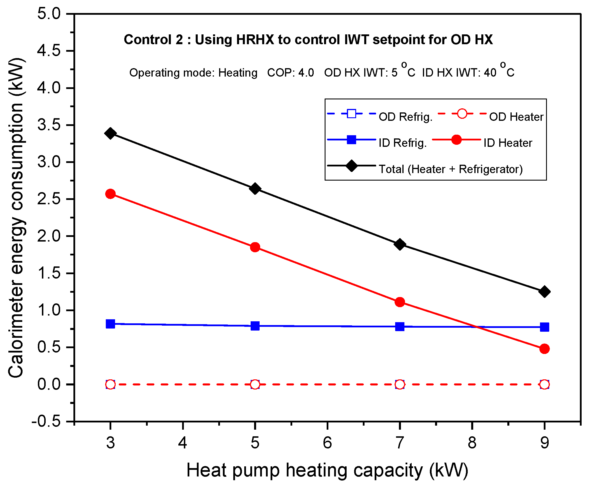
Figure 6 represent the calorimeter operating characteristics when the heat pump heating capacity was varied and control (2) was used in heating mode. For 
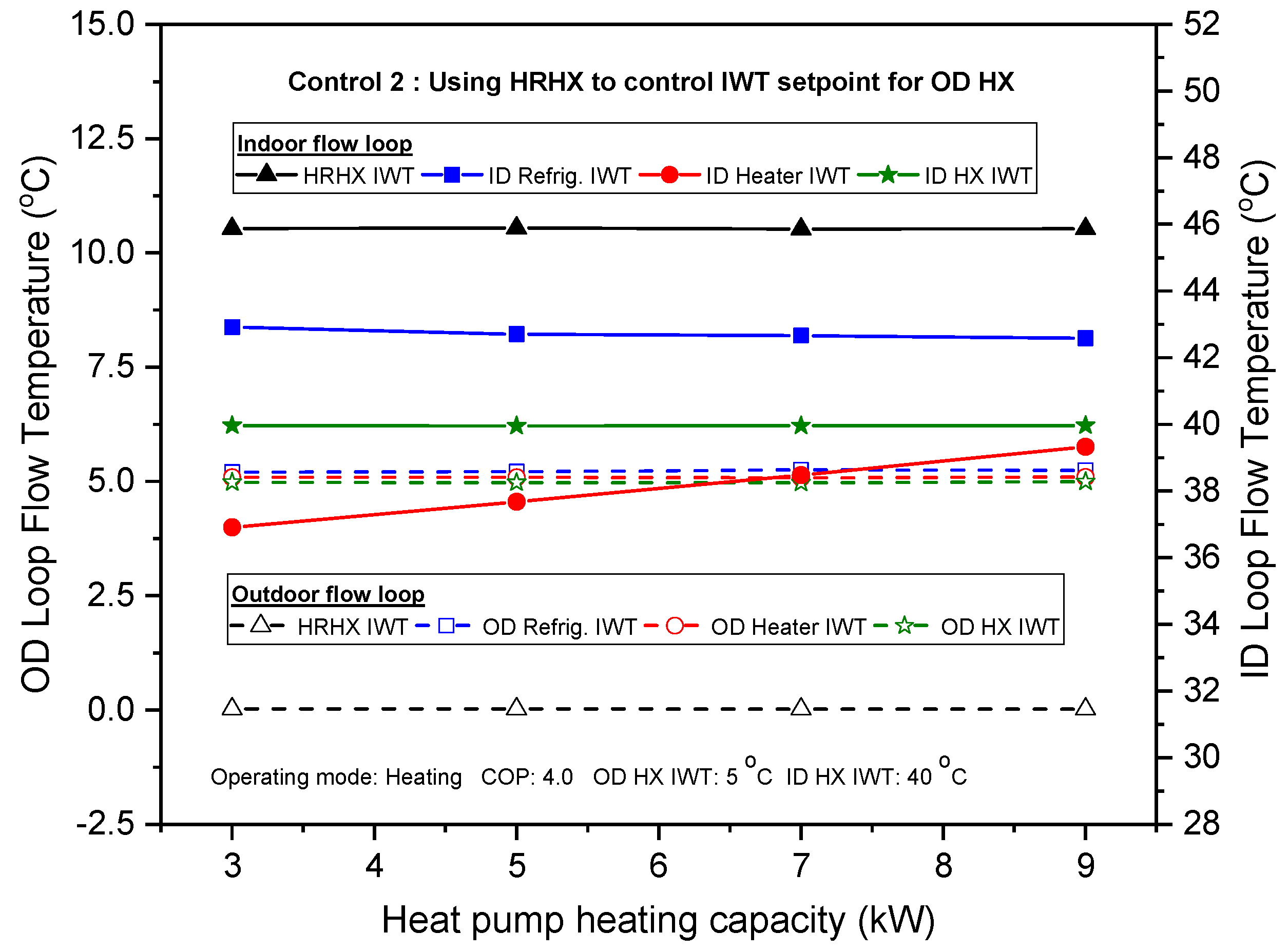
Figure 5, the inlet water temperature to the HR unit from the outdoor flow loop was lower than the IWT setpoint for the OD heat pump HX, and the IWT to the HR unit from the indoor flow loop was higher than the water inlet temperature setpoint for the ID HX.
Therefore, the needle valve was altered to control the heat transfer rate through the HR unit such that IWT to the OD heat pump HX was 5 °C. As a result, IWT values to the OD flow loop refrigerator and heater were similar to the water setpoint temperature for the outdoor HX. In this case, both the refrigerator and electric heater in the OD flow loop were switched off. Since the heat transfer rate in the HR unit from the indoor loop to outdoor loop increased with an increment in capacity, the IWT to ID refrigerator slightly decreased, however small. The ID refrigerator IWT was higher than the IWT setpoint of 40 °C for the ID heat pump HX. Hence, the ID loop refrigerator unit was operated. However, the required amount of heat extraction as a result of the increase in heating capacity was higher than the refrigeration capacity. Therefore, the inlet water temperature to the ID loop heater increased as the heating capacity was increased. Moreover, the indoor flow heater IWT was below the setpoint temperature for the indoor HX. Hence, the ID flow loop electric heater was turned on to control and maintain the IWT for the indoor heat pump HX. For energy consumption analysis, as shown in Figure 6, the outdoor heater and outdoor refrigerator were turned off due to heat recovery control, so the energy consumption for both units was zero. The indoor refrigerator utilized some energy because the inlet water temperature to the ID refrigerator increased above the IWT setpoint value for the ID heat pump HX.
However, the energy usage rate of the ID refrigerator became relatively the same as the heating capacity increased because the compressor of the refrigeration unit was operated at a constant speed and optimized at a low flow rate. As the inlet water temperature to the ID loop heater increased when the capacity was increased, the energy utilized by the ID heater to maintain the IWT setpoint decreased with an increase in the capacity. The calorimeter total energy utilized then decreased when the heating capacity was increased.
Table 3 indicates the energy consumption analysis of the calorimeter with heat recovery control methods and that of the conventional calorimeter for the water-to-water heat pump unit using the same set of operating test conditions in heating mode. As indicated in 
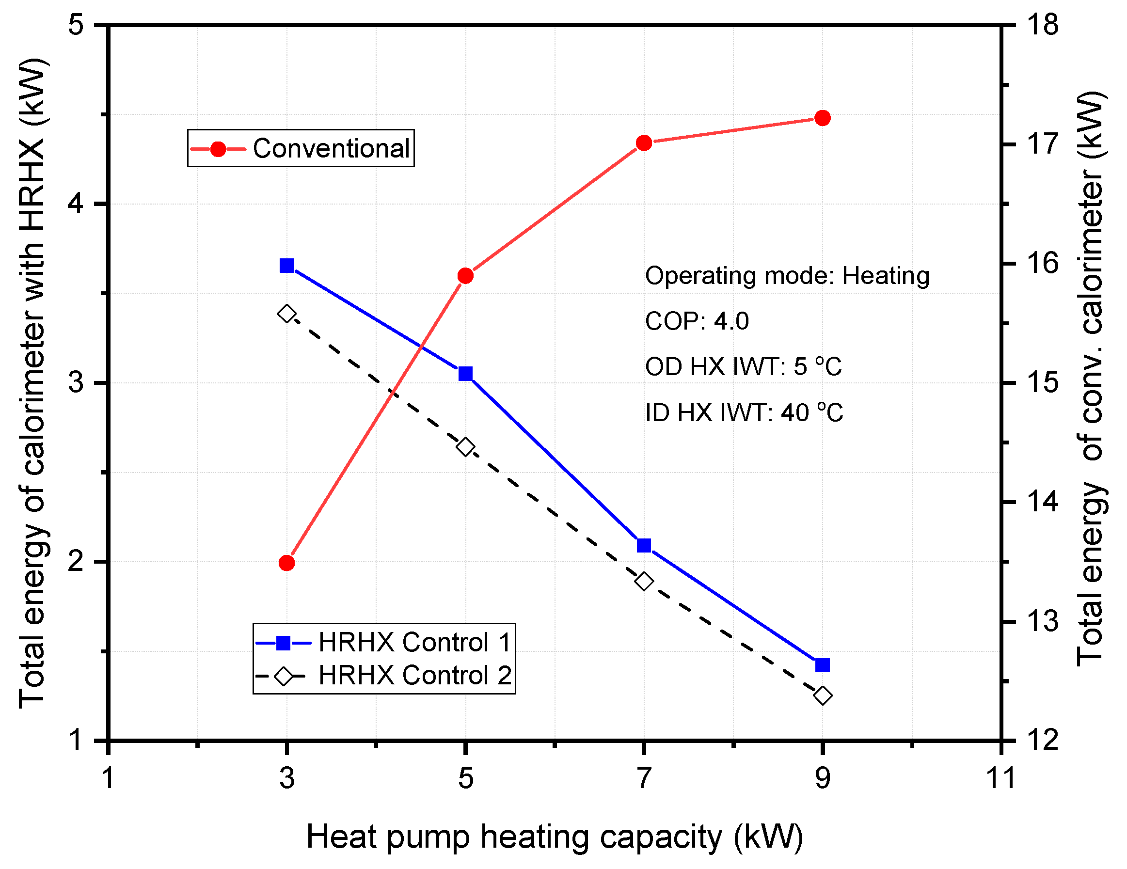
Figure 7, the total energy utilized by the conventional calorimeter showed an upward trend as the heat pump heating capacity increased. This was because, in the conventional calorimeter, there was no heat recovery unit and as such, the electric heater and refrigeration unit on both indoor and outdoor flow loops of the calorimeter were operated simultaneously when testing the heat pump unit.
Therefore, as the heat pump capacity was increased, the total power consumption also increased based on standard test conditions. However, the total energy utilization rate of the calorimeter with a heat recovery unit showed a downward trend as the heat pump heating capacity was increased. This was because the heat transfer rate in the heat recovery unit increased as the heating capacity increased, thereby decreasing the total power consumption of the calorimeter. Also, in Figure 7, as the heat pump heating capacity increased from 3 to 9 kW, the total energy utilization rate of the conventional calorimeter was about 73 to 89% higher than the calorimeter with heat recovery control methods. This was because the conventional calorimeter made use of two electric heaters and refrigeration units concurrently, whereas the calorimeter with a heat recovery unit only made use of one electric heater and refrigeration unit at the same standard test conditions for the heat pump unit.
Also, the refrigeration unit for the conventional calorimeter used a refrigerator capacity which was much larger compared to the refrigeration unit for the calorimeter with a heat recovery unit. Moreover, for the calorimeter with heat recovery control methods, when the control (1) method was adopted in the HR unit, the total energy increased between 8% and 13% compared to control (2). This showed that, for testing heat pumps in heating mode, it was better to use the heat recovery unit to control and maintain the inlet water temperature setpoint for the outdoor HX. Thus, control (2) was an optimum control option for the calorimeter with heat recovery compared to control (1) in heating mode.
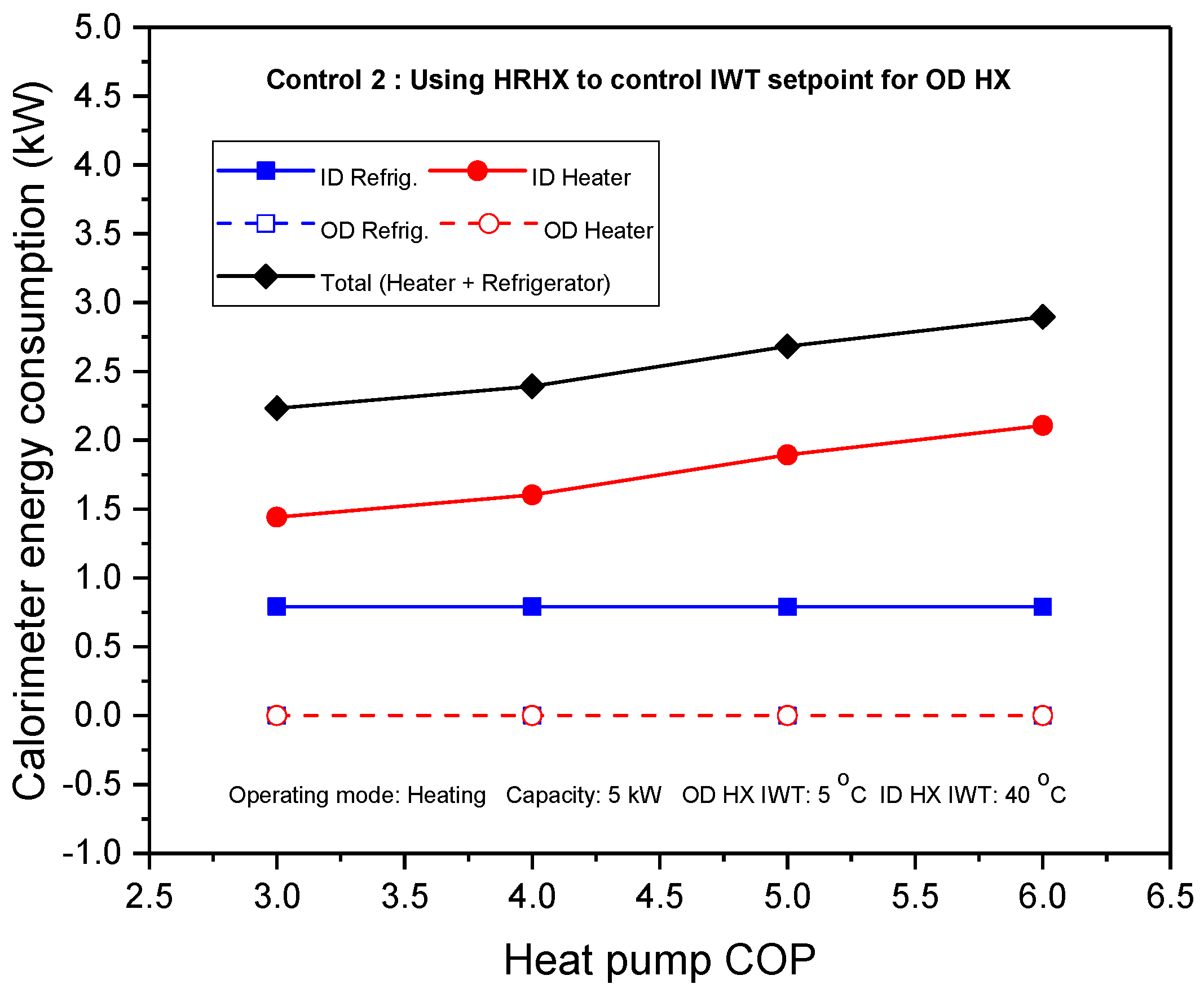
The heat recovery control (2) resulted in a lower energy consumption for the calorimeter than control (1) in heating mode. Hence, the calorimeter performance analysis in relation to heat pump COP variation was executed for the control (2) method. Figure 8 shows the measured flow loop temperature analysis. The inlet water temperature to the HR unit from the outdoor flow loop HX decreased as the COP increased, whereas the IWT from the indoor flow loop HX to the heat recovery unit was unchanged because the ID heat pump HX capacity remained unchanged. The inlet water temperature to the OD refrigerator was nearly the same as the inlet water temperature to the OD loop heater as a result of the control technique in the HR unit.
The inlet water temperature to the ID loop refrigerator decreased as the COP increased because the heat transfer rate in the HR unit was constant and therefore, IWT to the ID loop heater also decreased with an increment in COP. Figure 9 also represents the calorimeter energy analysis due to heat pump variation in COP. The OD heater and OD refrigerator energy consumption were zero because the OD flow loop was controlled with the HR unit. The ID loop refrigerator utilized energy as a result of heat extraction. However, ID refrigerator energy consumption was relatively uniform as the COP increased as a result of the constant operating speed of the compressor. Since the inlet water temperature to the indoor loop heater decreased because COP increased, the energy used by the ID heater to maintain the IWT setpoint also increased. The calorimeter total energy utilization rate increased by about 8% with an increase in the COP of the heat pump unit being tested.

3.2. Calorimeter Control Performance in Cooling Operating Mode

For test measurement in cooling operating mode, the water exit temperature from the OD heat pump HX increased, whereas the water exit temperature from the ID heat pump HX decreased. Figure 10 and 
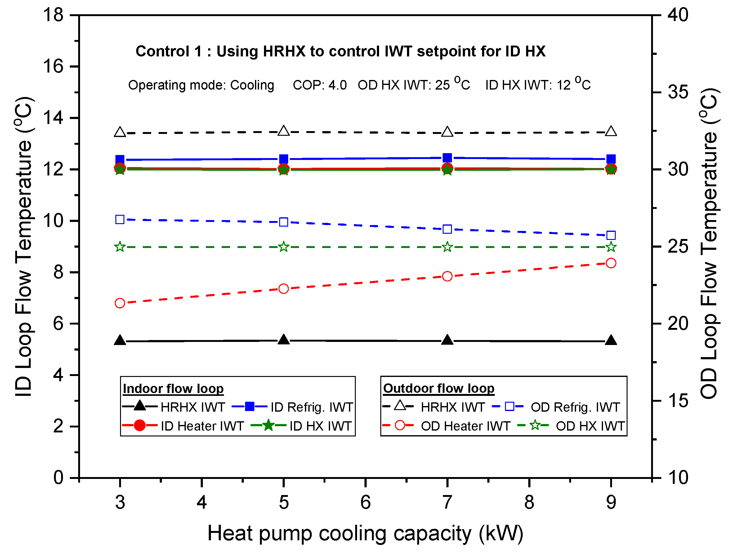
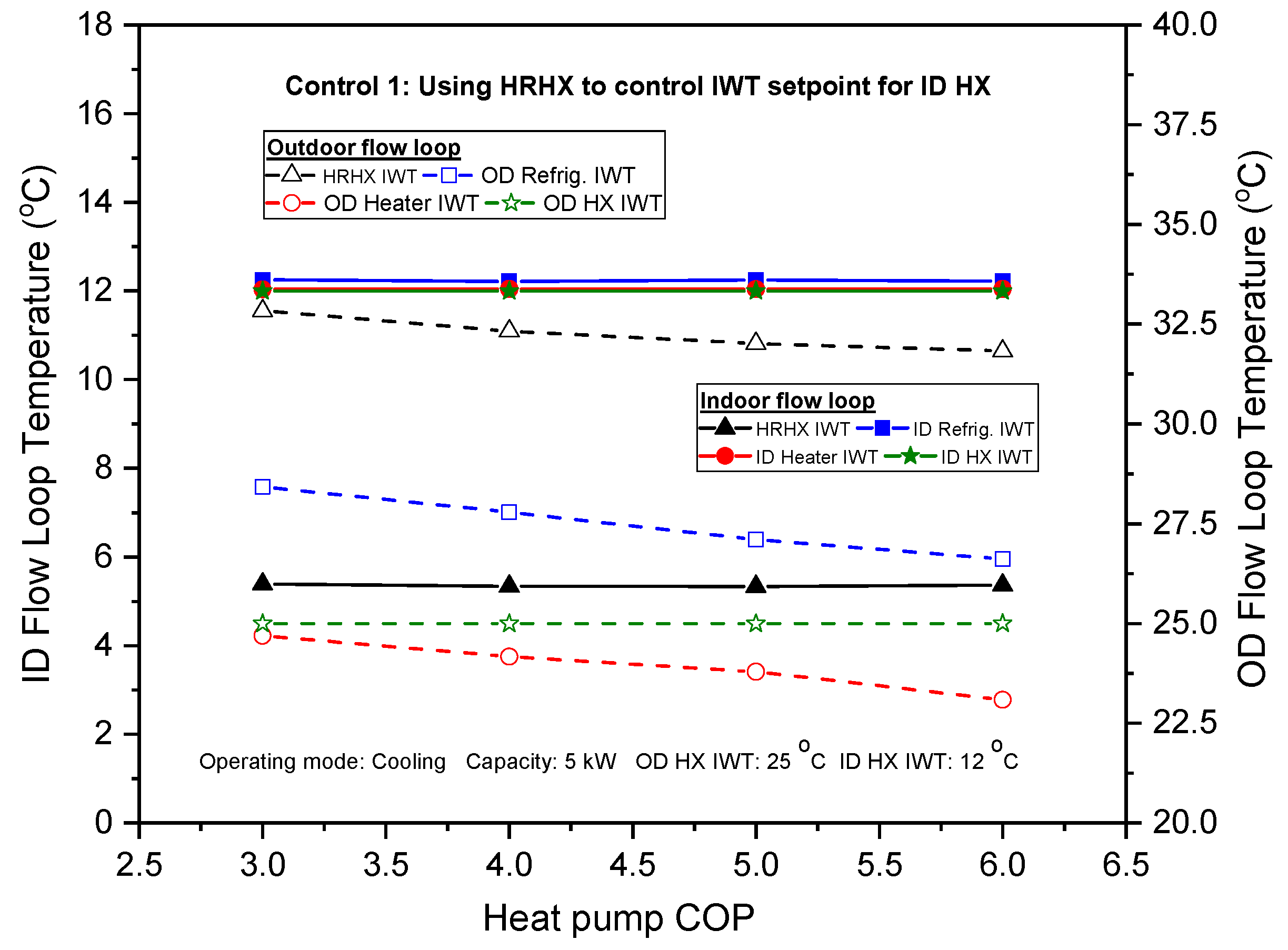
Figure 11 show the calorimeter performance analysis according to the cooling capacity in control (1). For the flow loop temperature analysis as shown in Figure 10, the water entering temperature to the heat recovery unit was relatively the same as the capacity increased for both indoor and outdoor flow loops because the flow rate was proportional to the heat pump cooling capacity. However, the inlet water temperature to the HR unit from the OD flow loop was higher than the IWT setpoint for the outdoor heat pump HX, whereas the inlet water temperature to the HR unit from the ID flow loop was lower than the IWT setpoint for the heat pump outdoor HX. Hence, the needle valve at the inlet of the HR unit was regulated to control the heat quantity through the HR unit so that the inlet water temperatures to the indoor loop refrigerator and heater were relatively equal to the inlet water temperature setpoint of 12 °C for the ID heat exchanger. Therefore, the ID refrigerator and ID heater were not activated. Also, due to heat transfer in the HR unit, IWT to the OD loop refrigerator slightly decreased when the cooling capacity was increased. However, the OD refrigerator IWT was higher than the standard temperature condition of 25 °C for the OD heat pump HX. As a result of heat discharged from the OD refrigerator, the inlet water temperature to the heater at the OD flow loop also decreased. But the IWT to the OD heater increased as the cooling capacity of the heat pump increased because the flow rate through the OD flow loop increased. The IWT to the OD loop heater was lower than the standard IWT setpoint for outdoor HX and so the OD heater was turned on.
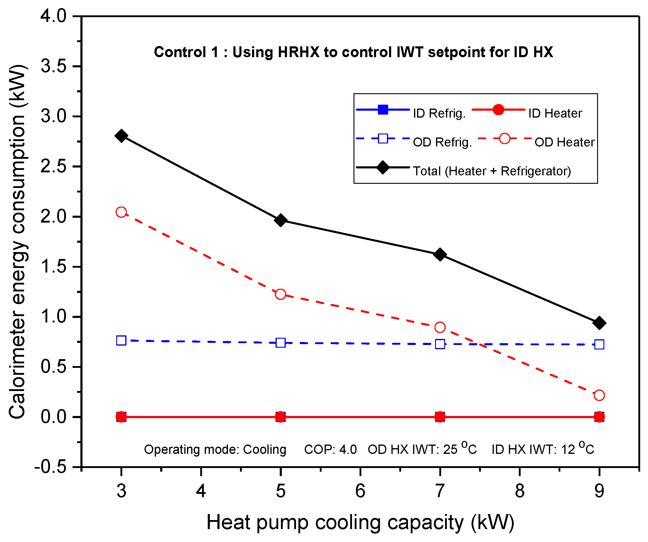
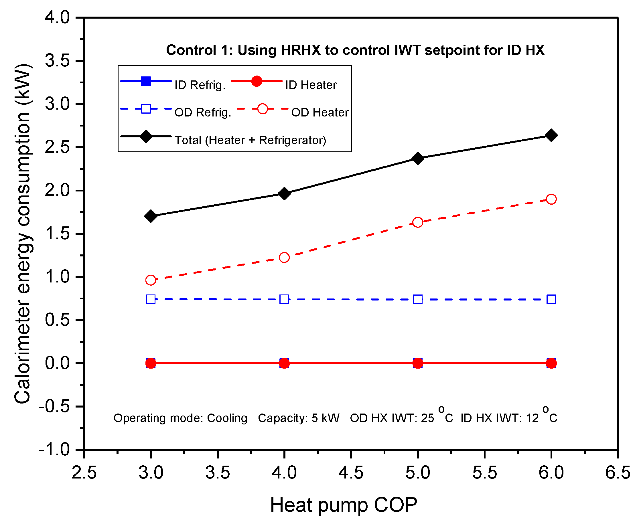
For energy consumption analysis using HR control (1) as shown in Figure 11, both the indoor heater and refrigerator were turned off since the ID flow loop control was conducted with the heat recovery unit. The OD refrigerator utilized some energy as a result of heat extraction. However, the rate of energy utilized by the OD loop refrigerator was somewhat unchanged as the cooling capacity increased due to the constant speed operation. The rate of energy metered by the OD loop heater decreased when the cooling capacity was increased because IWT to the OD loop heater also increased. Therefore, the total rate of energy utilized by the calorimeter also decreased when the cooling capacity was increased.
Figure 12 and 
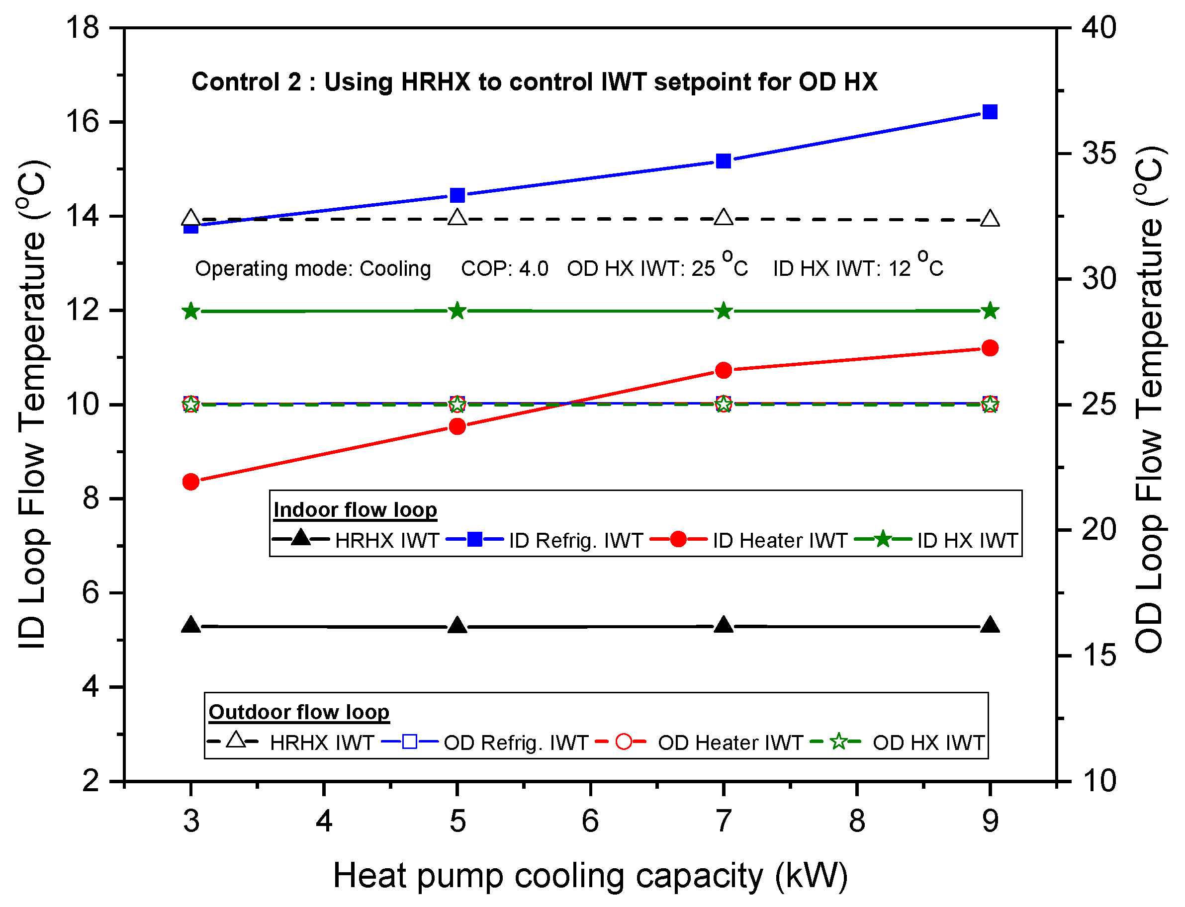
Figure 13 represent the calorimeter operating characteristics with the variation in capacity when control (2) was used for testing in cooling mode. In Figure 12, the inlet water temperature to the HR unit from the OD flow loop was higher than the inlet water setting temperature for the outdoor HX, whereas the IWT to the HR unit from the ID flow loop was lower than the IWT setpoint for the indoor HX. As such, the needle valve at the HR unit inlet was used to control the quantity of heat through the HR unit such that the IWT at the inlet to the OD heat pump HX was maintained at a setpoint of 25 °C. As the cooling capacity increased, the heat transfer rate in the HR unit increased, which then increased the inlet water temperature to the indoor refrigerator. Also, the inlet water temperature to the ID refrigerator was above the setpoint temperature of 12 °C for the ID heat pump HX. Therefore, the ID refrigeration unit was operated for heat extraction. However, the refrigerator capacity in the ID flow loop did not change so much. As a result, the ID heater IWT also increased as the cooling capacity was increased. However, the ID heater IWT was lower than the inlet water setpoint temperature for the ID heat pump HX. Therefore, the indoor loop heater was turned on to maintain the IWT setpoint for the ID heat pump HX.
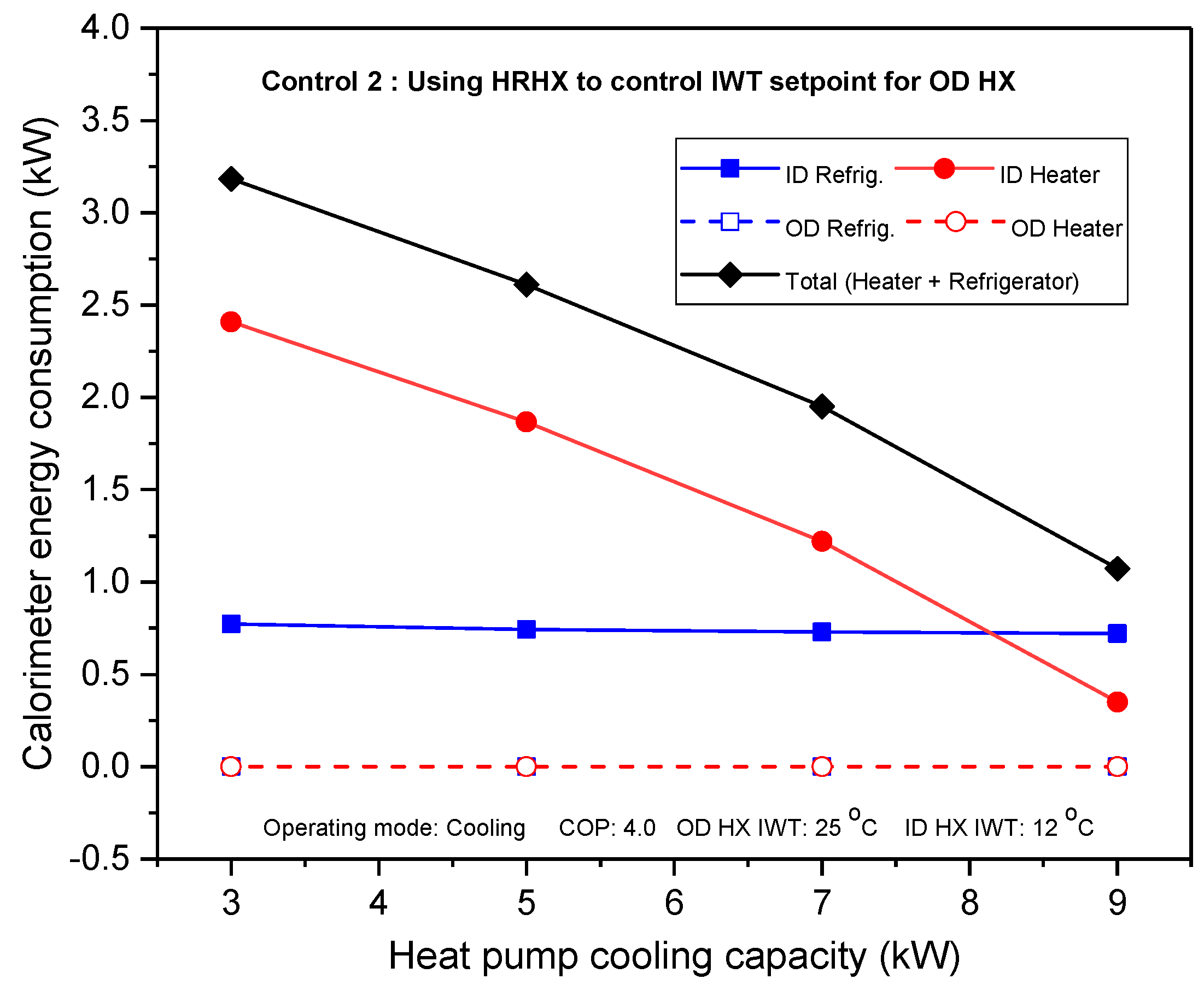
As shown in Figure 13, the OD heater and OD refrigerator were turned off to save energy because the IWT setpoint to the outdoor heat pump HX was controlled due to heat transfer between the indoor and outdoor flow loops through the HR unit. However, the ID refrigerator utilized energy as a result of heat extraction. The energy consumed by the ID refrigerator recorded almost the same value as the cooling capacity was increased because the refrigerator was operated at a constant speed. For the ID heater, since the IWT to ID heater was increased with an increment in cooling capacity, the energy utilized by the indoor heater to maintain the IWT setpoint decreased when the cooling capacity was increased. Therefore, the calorimeter total energy consumption decreased when the cooling capacity was increased.
Table 4 indicates the energy consumption analysis of the calorimeter with heat recovery control methods and that of the conventional calorimeter for the water-to-water heat pump unit with the same set of operating test conditions in cooling mode. 
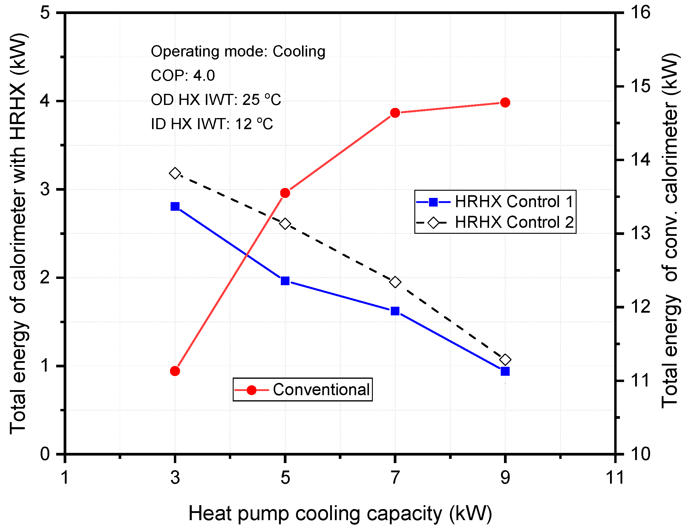
Figure 14 compares the total energy consumption of the calorimeter with heat recovery control methods to that of a conventional calorimeter. Similar to the heating operating mode, the total energy utilized by the conventional calorimeter showed an upward trend as the heat pump cooling capacity increased. This was because the conventional calorimeter without a heat recovery unit utilized both the electric heater and refrigeration unit in each flow loop of the calorimeter simultaneously.
Therefore, as the heat pump cooling capacity increased, the total power consumption also increased based on standard test conditions. However, the total energy utilization rate of the calorimeter with a heat recovery unit showed a downward trend as the heat pump cooling capacity was increased. This was because the heat transfer rate in the heat recovery unit increased as the cooling capacity increased. Hence, the total power consumption decreased with an increase in the cooling capacity.
Also, in Figure 14, as the heat pump cooling capacity increased from 3 to 9 kW, the total energy utilization rate of the conventional calorimeter was about 71 to 92% higher than that of the calorimeter with heat recovery control methods. The reason for this is that the conventional calorimeter utilized two electric heaters and refrigeration units at the same time, whereas the calorimeter with a heat recovery unit only made use of one electric heater and refrigeration unit under same heat pump test conditions.
Again, the refrigeration unit of the conventional calorimeter utilized a much larger refrigerator capacity compared to the case of the calorimeter with a heat recovery unit. Also, when the control (1) method was adopted in the HR unit, the total energy decreased between 6.4% and 21% as compared to control (2). This implied that, for the experiment in heat pump cooling mode, it was better to use the heat recovery unit to control and maintain the IWT setpoint for the ID heat pump HX. Thus, control (1) was an optimum control option when compared to control (2) in cooling mode.
Figure 15 and Figure 16 illustrate the calorimeter performance in terms of heat pump variation in COP using the heat recovery control (1) method in cooling mode. As indicated in Figure 15, the inlet water temperature to the HR unit from the indoor heat pump HX was relatively the same as the COP increased because the heat pump indoor HX capacity remained constant. The exit water temperature from the outdoor heat exchanger to the HR unit decreased because the OD heat pump HX capacity also decreased.
Therefore, needle valves were altered to control the heat exchange through the HR unit such that inlet water temperatures to the ID loop heater and refrigerator were equivalent to the IWT setpoint of 12 °C. The IWT to the OD loop refrigerator decreased as the COP was increased since the heat exchange rate in the HR unit was constant. Based on OD refrigerator heat extraction at a constant speed, IWT to the OD heater also decreased as the COP increased.
Figure 16 represents the energy consumption analysis as a result of COP variation. The ID loop heater and refrigerator energy consumption were zero because the ID flow loop was controlled with the HR unit. The OD loop refrigerator utilized energy because of heat extraction. However, the energy used by the OD refrigerator was relatively unchanged as the COP was increased. Since the IWT to the OD loop heater decreased as a result of the increase in the COP, the energy used by the OD heater to maintain the IWT setpoint increased when the COP was increased. The calorimeter total energy utilization rate increased by about 6.5% with an increase in the COP of the heat pump system being tested in cooling operating mode.

4. Conclusions

The calorimeter is the equipment used in testing the heat pump system to obtain performance data in order to rate and certify the heat pump. In the conventional testing mode and under standard conditions, the calorimeter utilizes a lot of energy through refrigeration and heating systems. The energy consumption rate of the conventional calorimeter for testing a water-to-water heat pump unit increased greatly under standard operating conditions. Therefore, it was necessary to adopt some novelty to reduce the energy consumption of the conventional calorimeter. Hence, in this study, a newly developed calorimeter with a heat recovery unit was used to investigate the performance of a water-to-water heat pump system. Tests were executed with variations in operating mode and standard temperature conditions as follows:
For heating operating mode, the inlet water setpoint temperature test conditions for the indoor and outdoor heat pump heat exchangers were 40 °C and 5 °C, respectively.
For cooling mode, the inlet water temperature setpoint conditions for the indoor and outdoor heat exchangers for the heat pump test unit were 12 °C and 25 °C, respectively.
To analyze the energy savings of the newly designed calorimeter, two control strategies were adopted in the system during test measurements. These control methods are outlined as follows:
In the control (1), the heat recovery unit was used to control the inlet water temperature setpoint for the heat pump indoor heat exchanger. In heating mode, this controlled temperature was 40 °C, whereas in cooling mode, it was 12 °C.
In the control (2), the heat recovery unit was used to control the inlet water temperature setpoint for the heat pump outdoor heat exchanger, with temperatures of 5 °C in heating mode and 25 °C in cooling mode.
The analyses of the experimental test results of the total energy consumption of the conventional calorimeter and newly proposed calorimeter with a heat recovery unit revealed the following:
In cooling mode, energy savings of the newly developed calorimeter were about 71% compared to the total rate of energy utilized in the conventional calorimeter under the same set of operating conditions.
In heating mode, energy savings of the newly developed calorimeter were about 73% in heating operating mode compared to the rate of energy utilized by the conventional calorimeter under the same set of operating conditions.
The energy consumption data for the newly proposed calorimeter were also compared based on the two control strategies. The following deductions were made:
It was observed that for the heat pump test in heating mode, the calorimeter performance was enhanced when the control (2) was used because the total energy savings in the control (2) were about 8 to 13% compared to the control (1).
For cooling operating mode, control (1) was an optimum control option when compared to control (2) as the total energy savings in control (2) were about 6.4 to 21% compared to control (2) method.
These deductions implied that for testing a water-to-water heat pump system in heating mode using the newly developed calorimeter, it is more energy efficient to use the heat recovery unit to control the outdoor flow loop setting temperature instead of controlling the indoor flow loop temperature, whereas in cooling mode, it is rather efficient to use the heat recovery unit to control the indoor flow loop setting temperature instead of using it to control the outdoor flow loop temperature.
Also, the energy consumption trend according to variation in the capacity of the heat pump unit was similar for both cooling and heating operating modes. However, the absolute amount of energy savings can be different depending on the heat pump unit capacity or the equipment, such as the refrigeration unit capacity of the calorimeter.

Author Contributions

K.O.A. and J.M.C. conducted the experiment and data analysis, and wrote this paper based on the obtained results.

Funding

This research was funded by the Korea Government Ministry of Trade, Industry & Energy [20163010111840].

Acknowledgments

This work has been conducted with support from the New & Renewable Energy of the Korea Institute of Energy Technology Evaluation and Planning (KETEP) grant and was funded by the Korea government Ministry of Trade, Industry & Energy (No. 20163010111840).

Conflicts of Interest

The authors declare no conflict of interest.

Nomenclature

cpspecific heat (kJ/kg·°C)
Qcooling or heating capacity (kW)
Ttemperature (°C)
Vvolume flow rate (m3/s)

Abbreviations

COPCoefficient of performance
EWTExit water temperature
HRHeat recovery
HXHeat exchanger
IDIndoor
IWTInlet water temperature
ODOutdoor
WTBWater temperature bath

Greek Symbols

Δdifference
ρdensity (kg/m3)

Subscripts

fsecondary fluid or water
hpheat pump unit

References

  1. Gagneja, A.; Pundhir, S. Heat Pump and Its Applications. Int. J. Adv. Chem. Eng. Biol. Sci. 2016, 3, 117–120. [Google Scholar] [CrossRef]
  2. Chua, K.J.; Chou, S.K.; Yang, W.M. Advances in heat pump systems: A review. Appl. Energy 2010, 87, 3611–3624. [Google Scholar] [CrossRef]
  3. Jovane, F.; Yoshikawa, H.; Alting, L.; Boer, C.R.; Westkamper, E.; Williams, D.; Tseng, M.; Seliger, G.; Paci, A. The incoming global technological and industrial revolution towards competitive sustainable manufacturing. CIRP Ann. 2008, 57, 641–659. [Google Scholar] [CrossRef]
  4. Abdallah, M.; Khaled, E.R.; Caroline, C. Minimizing energy consumption and carbon emissions of aging buildings. In Proceedings of the International Conference on Sustainable Design, Engineering and Construction, Chicago, IL, USA, 10–13 May 2015; pp. 886–893. [Google Scholar]
  5. Allaerts, K.; Koussa, J.A.; Desmedt, J.; Salenbien, R. Improving the energy efficiency of ground-source heat pump systems in heating dominated school buildings: A case study in Belgium. Energy Build. 2017, 138, 559–568. [Google Scholar] [CrossRef]
  6. Mohamed, R.H.; Abdel, S.; Melanie, F.; Gaoming, G.; Besant, R.W.; Simonson, C.J. Expected energy and economic benefits, and environmental impacts for liquid-to-air membrane energy exchangers (LAMEEs) in HVAC systems: A review. Appl. Energy 2014, 127, 202–218. [Google Scholar] [CrossRef]
  7. Willem, H.; Lin, Y.; Lekov, A. Review of energy efficiency and system performance of residential heat pump water heaters. Energy Build. 2017, 143, 191–201. [Google Scholar] [CrossRef]
  8. Kouropoulos, G.P. Review of the Capacity Control Capability of Commercial Air Conditioner Units with Variable Speed Compressor. Int. J. Air-Cond. Refrig. 2016, 24. [Google Scholar] [CrossRef]
  9. Liu, H.; Zhou, Q.; Zhao, H. Experimental study on cooling performance and energy saving of gas engine-driven heat pump system with evaporative condenser. Energy Convers. Manag. 2016, 123, 200–208. [Google Scholar] [CrossRef]
  10. Vakiloroaya, V.; Samali, B.; Fakhar, A.; Pishghadam, K. A review of different strategies for HVAC energy saving. Energy Convers. Manag. 2014, 77, 738–754. [Google Scholar] [CrossRef]
  11. Elraheim, D.A.; Mahmoud, O.E.; Fatouh, M. Experimental Assessment of a Domestic Split Type Air-Conditioner Working with R410A. Int. J. Air-Cond. Refrig. 2016, 24. [Google Scholar] [CrossRef]
  12. Shi, Y.; Guo, X.; Zhang, X. Study on Economized Vapor Injection Heat Pump System Using Refrigerant R32. Int. J. Air-Cond. Refrig. 2016, 24. [Google Scholar] [CrossRef]
  13. Gao, J.; Huang, G.; Xu, X. An optimization strategy for the control of small capacity heat pump integrated air-conditioning system. Energy Convers. Manag. 2016, 119, 1–13. [Google Scholar] [CrossRef]
  14. Madani, H.; Claesson, J.; Lundqvist, P. A descriptive and comparative analysis of three common control techniques for an on/off controlled Ground Source Heat Pump (GSHP) system. Energy Build. 2013, 65, 1–9. [Google Scholar] [CrossRef]
  15. European Standards Committee. Testing and Rating Conditions for Air Conditioners, Liquid Chilling Packages and Heat Pumps for Space Heating and Cooling; Comité Européen de Normalization (CEN): Brussels, Belgium, November 2007. [Google Scholar]
  16. International Organization for Standardization. Water-Source Heat Pumps-Testing and Rating for Performance—Part 2: Water-To-Water and Brine-To-Water Heat Pumps; International Standard Organization (ISO): Geneva, Switzerland, August 1998. [Google Scholar]
  17. ASHRAE. Methods of Testing for Seasonal Efficiency of Unitary Air-Conditioners and Heat Pumps; American Society of Heating, Refrigerating and Air Conditioning Engineers (ASHRAE): Atlanta, GA, USA, 1983. [Google Scholar]
  18. NR GT 101. KEMCO: Rating Test Standards for Water-To-Water Ground Source Heat Pump; Korea Energy Management Cooperation (KEMCO): Yongin, Korea, 2008. [Google Scholar]
  19. Wang, D.; Yu, B.; Hu, J.; Chen, L.; Shi, J.; Chen, J. Heating performance characteristics of CO2 heat pump system for electrical vehicle in a cold climate. Int J. Refrig. 2018, 85, 27–41. [Google Scholar] [CrossRef]
  20. Jie, J.; Jingyong, C.; Wenzhu, H.; Yan, F. Experimental study on the performance of solar-assisted multi-functional heat pump based on enthalpy difference lab with solar simulator. Renew. Energy 2015, 75, 381–388. [Google Scholar] [CrossRef]
  21. Lee, H.S.; Won, J.P.; Cho, C.W.; Kim, Y.C.; Lee, M.Y. Heating performance characteristics of stack coolant source heat pump using R744 for fuel cell electric vehicles. J. Mech. Sci. Technol. 2012, 7, 2065–2071. [Google Scholar] [CrossRef]
  22. Park, Y.S.; Jeong, J.H.; Ahn, B.H. Heat pump control method based on direct measurement of evaporation pressure to improve energy efficiency and indoor air temperature stability at a low cooling load condition. Appl. Energy 2014, 132, 99–107. [Google Scholar] [CrossRef]
  23. Korean Agency for Technology and Standards. Performance Measurement for Air Conditioners; Korea Energy Standards: Chungcheong-buk do, Korea, 1999. [Google Scholar]
  24. Carrington, C.G.; Liu, Q. Calorimeter measurements of a heat pump dehumidifier: Influence of evaporator air flow. Int. J. Energy Res. 1995, 19, 649–658. [Google Scholar] [CrossRef]
  25. Jung, H.W.; Kang, H.; Yoon, W.J.; Kim, Y. Performance comparison between a single-stage and a cascade multi-functional heat pump for both air heating and hot water supply. Int. J. Refrig. 2013, 36, 1431–1441. [Google Scholar] [CrossRef]
  26. Baek, C.; Heo, J.; Jung, J.; Cho, H.; Kim, Y. Optimal control of the gas-cooler pressure of a CO2 heat pump using EEV opening and outdoor fan speed in the cooling mode. Int. J. Refrig. 2013, 36, 1276–1284. [Google Scholar] [CrossRef]
  27. Fan, H.; Shao, S.; Tian, C. Performance investigation on a multi-unit heat pump for simultaneous temperature and humidity control. Appl. Energy 2014, 113, 883–890. [Google Scholar] [CrossRef]
  28. Kim, M.H.; Bullard, C.W. Dynamic characteristics of R-410A split air conditioning system. Int. J. Refrig. 2001, 24, 652–659. [Google Scholar] [CrossRef]
  29. Amoabeng, K.O.; Choi, J.M.; Lee, K.H. A study on the performance characteristics of a testing facility for a water-to-water heat pump. Int. J. Refrig. 2018, 86, 113–126. [Google Scholar] [CrossRef]
  30. Schroder, E.; Thomauske, K.; Schmalzbauer, J.; Herberger, S.; Gebert, C.; Velerska, M. Design and test of a new flow calorimeter for online detection of geothermal water heat capacity. Geothermics 2014, 53, 202–212. [Google Scholar] [CrossRef]
  31. Rodolfo, C.; Flesch, C.; Julio, E.; Normey, R. Modeling, identification and control of a calorimeter used for performance evaluation of a refrigerant compressors. Control Eng. Pract. 2010, 18, 254–261. [Google Scholar]
  32. American National Standards Institute. Standard Method for Temperature Measurement; American Society of Heating, Refrigerating and Air Conditioning Engineers (ASHRAE): Atlanta, GA, USA, 1986. [Google Scholar]
Figure 1. Calorimeter to measure heating performance characteristics of a heat pump system [19].
Energies 11 02210 g001
Figure 2. Newly developed calorimeter test rig for a water-to-water heat pump.
Energies 11 02210 g002
Figure 3. Flow loop temperature with variation in heat pump heating capacity for control (1).
Energies 11 02210 g003
Figure 4. Calorimeter energy analysis with variation in heat pump heating capacity for control (1).
Energies 11 02210 g004
Figure 5. Flow loop temperature with variation in heat pump heating capacity for control (2).
Energies 11 02210 g005
Figure 6. Calorimeter energy consumption with variation in heat pump heating capacity for control (2).
Energies 11 02210 g006
Figure 7. Total energy analysis for a conventional calorimeter and the heat recovery calorimeter in heating mode.
Energies 11 02210 g007
Figure 8. Flow loop temperature with heating COP variation in control (2).
Energies 11 02210 g008
Figure 9. Calorimeter energy consumption with heating COP variation in control (2).
Energies 11 02210 g009
Figure 10. Flow loop temperature with variation in heat pump cooling capacity for control (1).
Energies 11 02210 g010
Figure 11. Calorimeter energy consumption with variation in heat pump cooling capacity for control (1).
Energies 11 02210 g011
Figure 12. Flow loop temperature with variation in heat pump cooling capacity for control (2).
Energies 11 02210 g012
Figure 13. Calorimeter energy consumption with variation in heat pump cooling capacity for control (2).
Energies 11 02210 g013
Figure 14. Total energy analysis for a conventional calorimeter and the heat recovery calorimeter in cooling mode.
Energies 11 02210 g014
Figure 15. Flow loop temperature with cooling COP variation in control (1).
Energies 11 02210 g015
Figure 16. Calorimeter energy consumption with cooling COP variation in control (1).
Energies 11 02210 g016
Table 1. Specification of calorimeter and sensors.
ItemSpecification
CalorimeterHeat ExchangerPlate TypeRated HX Capacity: 10.5 kW
Refrigeration unitCompressorRefrigerant: R410 A
Rated Frequency: 50 Hz
EvaporatorRated HX capacity: 3.6 kW
Expansion valveElectronic expansion valve
CondenserRated HX capacity: 6 kW
Heat recovery unitPlate typeRated capacity: 10.5 kW
Magnetic flow pump3-phase inverter drivenRated frequency: 60 Hz
Electric heating unitFlange heaterRated capacity: 12 kW
SensorsRTD sensorA-classAccuracy: ±0.1 °C
Volumetric flow meterMagnetic typeAccuracy: ±0.1% of full scale
Power measuring device3-phase/4-wiringAccuracy: ±0.1% of reading scale
Table 2. Experimental test conditions.
Heat PumpOperating Mode
ParameterUnitHeatingCooling
IWT for ID HX°C4012
IWT for OD HX°C525
CapacitykW3, 5, 7, 93, 5, 7, 9
COP-3, 4, 5, 63, 4, 5, 6
Table 3. Energy consumption data for a conventional calorimeter and the proposed calorimeter with a heat recovery unit in heating mode.
Test Unit Capacity (kW)Energy Consumption of Conventional Calorimeter (kW)Energy Consumption of Proposed Calorimeter with Heat Recovery Unit (kW)
Control Method 1Control Method 2
HeaterRefrig.TotalHeaterRefrig.TotalHeaterRefrig.Total
9.013.373.8517.220.650.771.420.480.771.25
7.013.083.9317.011.310.782.091.110.781.89
5.011.884.0415.922.260.803.061.850.792.64
3.09.344.1413.482.830.823.652.570.823.39
Table 4. Energy consumption data for a conventional calorimeter and the proposed calorimeter with heat recovery unit in cooling mode.
Test Unit Capacity (kW)Energy Consumption of Conventional Calorimeter (kW)Energy Consumption of Proposed Calorimeter with Heat Recovery Unit (kW)
Control Method 1Control Method 2
HeaterRefrig.TotalHeaterRefrig.TotalHeaterRefrig.Total
9.010.993.7914.780.220.720.940.350.721.07
7.010.843.8014.640.890.731.621.220.731.95
5.09.723.8313.551.220.741.961.870.742.61
3.07.283.8511.132.050.762.812.410.773.18

