1. Introduction
The point absorber devices with direct drive extraction mechanism are the more efficient systems for ocean wave energy conversion at low velocity oscillations [
1]. For this type of conversion devices, linear generators with permanent magnets are generally used [
2,
3,
4,
5,
6]. However, linear electric machines with permanent magnets need a complicated winding system and are characterized by their elevated construction and assembly costs. This type of machine is affected by the gradual demagnetization of the permanent magnets, which may reduce the machine efficiency and compromise its operation [
7]. With the absence of permanent magnets in its configuration, the switched reluctance machine is a strong alternative as linear generator for direct conversion devices. It is suitable for low speed operation, presents a robust and low cost construction and is characterized by a high reliability [
8]. In point absorbers, motion is induced by the ocean waves to drive a power-take-off (PTO) system for the generation of useful energy [
9]. Maximum power absorption can be attained when the frequency of the floating body matches the frequency of the incoming ocean waves, where the excitation force is in phase with the velocity of the oscillating body. However, since the ocean waves are characterized by a variable behavior, an active control needs to be applied to improve the conversion efficiency of the device among the different sea states [
10].
The control of an ocean wave converter aims to adjust the PTO load in order to achieve the optimal oscillation phase and amplitude, required for maximum power absorption [
11]. The point absorber converter can operate under continuous control or discrete control. In continuous control, an optimum load force is provided by the PTO system to regulate the amplitude and/or the phase of the floating body motion. With latching control, which belongs to the category of discrete control, the motion of the floating body is held until the incoming wave force achieves the most suitable phase value [
12]. The complex-conjugate control and passive loading are the continuous control techniques with more acceptance for point absorber devices [
11]. The former seeks a resonant motion of the floating body by changing respective amplitude and phase while the latter only modifies the amplitude by adjusting the converter dynamic resistance to improve the power absorption from the incoming waves. In [
13], a control strategy based on fuzzy logic is proposed to control the amplitude and phase of a point absorber device to enhance the respective power capture. A passive loading strategy is presented in [
14] to control a point absorber device with a linear permanent magnet synchronous generator as PTO. The control is applied in the electronic power converter by emulating the electric resistance of the generator in order to maximize the wave power extraction. With the same objective, in [
15], the current of the generator is regulated by changing the converter DC link voltage for an optimal value. With this strategy, the electrical load in the generator can be modified and, as consequence, the most favorable damping may be provided by the ocean wave converter. In [
16] are proposed reactive and latching control strategies for a direct-drive point absorber to maximize the electric power output instead of power extracted by the device. These strategies aims to reduce the copper losses in a permanent magnet linear generator and to increase the energy extraction near the device excursion limits. Model predictive control is another technique that has been adopted for ocean wave converters. In this type of control, the system behavior is predicted over a short time horizon in order to estimate the optimal damping force to be applied for maximum energy extraction [
17]. A nonlinear model predictive control has been implemented and tested by Son and Yeung [
18] on a lab-scale permanent-magnet linear generator. A damping control control strategy has been proposed in [
19] for high-speed operation of ocean wave energy converter with a linear permanent magnet synchronous generator. In [
20], a novel robust model predictive control is presented for application in heaving wave energy converters to maximize the power conversion output while accounting with the device motion constraints. In the latter approach, the PTO force is parameterized using orthogonal polynomials in order to reduce the computational complexity verified in standard model predictive control techniques.
The maximum power point tracking control technique (MPPT), widely used in renewable energy converters, has shown promising results when applied to the control of a point absorber device with a permanent magnet linear generator, as experimentally demonstrated by Lettenmaier et al. [
21]. The proposed strategy regulates the electric load according to the change verified in the ocean wave converter output power. In [
22] is proposed an MPPT technique that applies an active phase control in a point absorber device with a linear permanent magnet generator. The generator damping is modified according to the wave period to reduce the phase difference between the system velocity and excitation force in order to reach the maximum power point absorption.
In the present paper, a MPPT strategy to control a tubular linear switched reluctance generator (TLSRG) that serves as PTO in a point absorber device is proposed.
The work was developed to promote the application of tubular linear switched reluctance generators direct-drive ocean wave energy converters. Since this type of machine offers unique advantages, it is of extreme importance to develop practical and efficient techniques for its control and operation to make it a a reliable and attractive solution. Unlike the majority of the optimal control techniques for this type of ocean wave converters, the proposed approach does not use the dynamical model of the device to predict optimal behavior. Moreover, the proposed control strategy does not require additional hardware for its operation. Thus, the complexity of controller is heavily reduced which makes it easier to implement.
2. System Description
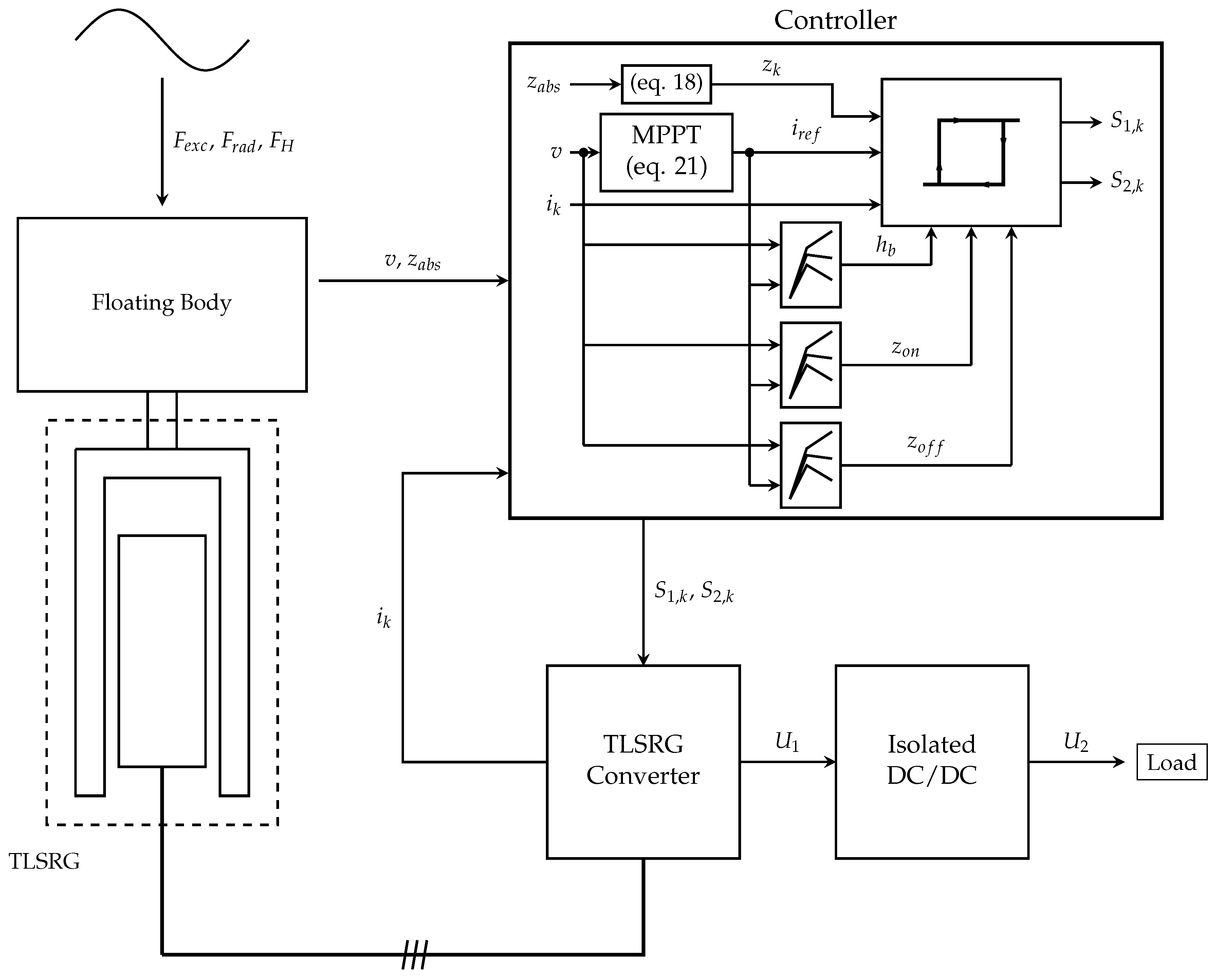
The configuration of the point absorber conversion system with the proposed approach is illustrated in
Figure 1. The representative blocks of each subsystem are described in detail.
The point absorber device illustrated in
Figure 2 is considered in the present work to evaluate the performance of the TLSRG as PTO. The conversion system is characterized by a floating buoy of cylindrical shape and a floating submerged reference system where the TLSRG is held. The reference system is assumed to be fixed to bottom by means of mooring cables. Thus, only heave motion is allowed for the floating buoy and for the movable part of the TLSRG, which are assumed to be rigidly connected. A mechanical spring is considered to connect the oscillating body to the reference system in order to assist the body motion, if necessary.
The TLSRG, used as PTO system, is illustrated in
Figure 3. The electromagnetic structure is derived from the flat switched reluctance machine evaluated in [
7] and was already proposed and analyzed as tubular generator in [
23].
The TLSRG has three electric phases with one coil of turns per phase. Each electric phase possesses a distinct magnetic circuit, separated from the adjacent phases by a non-magnetic element.
The mathematical model of the switched reluctance machine is obtained through the electrical analysis of the power electronic converter used for the linear switched reluctance generator. In the present work, the H-bridge asymmetric converter is adopted to control the process of electromechanical energy conversion in the generator. The converter topology for one phase is shown in
Figure 4. Since all electric phases have the same electric circuit configuration, the mathematical model is generalized for just one.
A DC/DC converter is used to control the electric energy flux between the TLSRG converter and the load, as schematized in
Figure 1. Thus, the voltage levels at the DC bus and at the load terminals can be properly adjusted to improve the system performance. For the present work, an isolated H-bridge DC/DC converter is adopted. Since the purpose of the DC/DC is to regulate the energy delivered to the load by means of pulse width modulation, its parameters are not designed and, therefore, an ideal converter is assumed. The latter is illustrated in
Figure 5.
4. Proposed Control
The operation of a switched reluctance machine is conditioned by the electric positions where the electronic switches are commutated. With fixed positions, especially at variable velocities, the system may become unstable leading to significant changes in voltage, according to the electric load of the converter. Thus, to avoid this undesirable behavior, there is the need to apply a closed loop control to the machine.
In the operation as a generator, the control must be applied to preserve the converter DC bus electric voltage and achieve maximum conversion efficiency [
27]. The voltage of the DC bus can be maintained within a pretended value by using a DC/DC converter to regulate the energy supplied to the load [
28]. The conversion efficiency relies on the overall system behavior which, for the present application, is conditioned by the damping of the electromechanical force exerted by the TLSRG. Therefore, the maximum performance can be achieved by adapting the strength and duration of the referred force, controlling the electric phase current intensity and the electronic switch commutation positions.
Point absorber devices are characterized by long period oscillations. Consequently, a low frequency operation is expected for the TLSRG under evaluation. For this operating condition, the electromotive force developed at the generator phase terminals may not be sufficient to overcome the DC bus voltage and, thus, the phase current may be forced to diminish progressively, leading to a premature extinction. To avoid this drawback, the current intensity must be maintained near a reference value by regulating the voltage applied to the electric phase with an hysteresis or pulse with modulation controller [
29,
30].
The control of the TLSRG comprises the selection of the appropriate values for the parameters responsible for its performance. At high velocities, where the induced electromotive force is superior to the DC bus voltage, only the electric positions are accounted. At low velocities, a reference value for the electric phase current must also be considered.
The optimal control parameters can be computed off-line and related with the physical entities that reflects the machine performance. The optimal values can be determined with experimental measurements or computed with the generator mathematical model and included in the control process through look-up tables or mathematical expressions. With this approach, the appropriate values for the control parameters can be defined as function of the generator operation variables [
31]. Other techniques applied in switched reluctance generator use a PI controller to perform on-line estimation of the optimal control parameters. In [
7], the PI controller is adopted to regulate the electric phase current intensity of linear switched reluctance generator in order to minimize the converter output ripple.
However, despite the simplicity and robustness of the PI controller, its performance is strongly affected when the system is characterized by a non-linear behavior or when the control parameters are modified. For this case, control techniques based on artificial intelligence are a better approach due to the ability to handle the non-linearities of the system to be controlled [
32].
The amount of energy available in ocean waves is not constant, although it may be characterized by a well defined periodicity during long periods. Thus, since the wave power changes over time, an adaptive control must be applied to ensure that the converter always extracts the maximum available energy. This can be achieved with maximum power point tracking (MPPT), a technique that has been already applied as the control of linear permanent magnet generator to attain maximum power absorption in a direct drive points absorber [
33]. Concerning the switched reluctance machine, the MPPT was adopted by Xiong et al. [
34] to control a rotating generator in a wind conversion device.
4.1. Hysteresis Control
The hysteresis control is applied to confine the phase current intensity close to a reference value. The need for this type of control arises from the low speed operation expected for the TLSRG which, usually, leads to the development of an electromotive force lower than the DC bus voltage.
In the hysteresis control, the error
, given by the difference between the phase current
i and the respective reference value
, is maintained within a range of values defined by the hysteresis band
. When the error is higher than
, the electronic switches are closed to apply the converter bus voltage
to the phase terminals to increase its current value. When
is lower than
, the electronic switches are opened and the phase is subjected to a negative voltage
forcing the respective current to decrease [
35]. Thus, with the hysteresis control, the generator conversion cycle is defined by successive excitation and generation periods.
Figure 7a shows the typical current profile obtained by the hysteresis control.
Figure 7b shows the respective control logic diagram. In each electric phase, the generation cycle is initiated at the electric position
, when the electric switches are closed to energize the coils, and it finishes at the position
, where the electric current starts to decrease until is extinguished at the position
.
4.2. MPPT
The adopted MPPT technique for the present system is similar to the algorithm proposed by Xiong et al. [
34] for a rotative switched reluctance generator, where the current in the electric phases is adjusted to provide the optimal torque for maximum electric power output. However, in the present work, instead of the electric power output, the velocity of the oscillating body is accounted as a measure of the system power conversion. Since the former is subjected to an higher rate of change, as a consequence of the successive excitation/generation cycles, it is difficult to follow its value in order to provide an appropriated control.
Knowing the velocity of the movable part of the TLSRG, its linear force can be controlled to follow the load induced by the ocean waves. This process is accomplished by regulating the electric current in each phase of the TLSRG. When the absolute value of the velocity increases, the acceleration of the oscillating system is positive, which implies positive net force on the oscillating body. In this situation, the electric phase current intensity can be raised to increase the damping provided by the TLSRG and, as a consequence, the conversion of kinetic energy in to electricity as well. As the wave excitation force starts to diminish, the generator becomes over-damped and the velocity starts to decrease, reducing the amount of kinetic energy available for conversion. Therefore, the electric phase current must be continuously reduced while a loss of velocity is verified. To apply the described control procedure, the reference value
for the electric current is computed by:
where
is the incremental value defined for
and
is the maximum value allowed for the latter.
Equation (
21) allows establishing the reference value for the electric phase current at the instant
t. This value, given between 0 and
, is subjected to an update period
. For a correct control operation, the values for the hysteresis band
, the switch on position
and the switch off position
shall be properly selected. In the present work, the referred parameters are selected as function of the velocity
v and reference current
from a set of optimal values. These values are previously computed to achieve maximum power generation for given combination of velocity and reference current. Look-up tables are used to store the values and they are assessed by the controller using linear interpolation.
4.3. Proportional Integral (PI) Control
The voltage of the converter DC bus is regulated by a proportional and integral (PI) controller, which provides the value of the duty-cycle
to be applied to the isolated DC/DC converter according to the error verified between the DC bus voltage and its reference value. The mathematical expression for the PI controller is given in [
36] by:
where
s is the control variable,
e is the error associated with the entity to be controlled and
and
are the proportional and integral gains, respectively.
The value of the duty-cycle supplied to the isolated DC/DC is defined by an initial value
and by the result returned from the PI controller
:
The parameter
is obtained through:
where
is the normalized error between the voltage in the DC bus and the respective reference value
:
5. Results and Analysis
To evaluate the performance of the TLSRG as a PTO, a regular wave was considered to represent a sea state with a significant height of 4.4 m and a energetic period of 7.7 s. The floating body was defined with a radius of 1.5 m and a vertical extension
of 5.6 m. The TLSRG has been designed with the capability to provide a mean damping force of, approximately, 120 kN, which is the maximum value expected for the ocean wave excitation force. Since the only concern is the control of the TLSRG, the respective electromagnetic design is omitted in the present work. The M19 silicon-steel is used as magnetic material, assuming that the ferromagnetic core is made of longitudinal laminations, radially oriented. The dimensions of the TLSRG, according to the nomenclature of
Figure 3, are presented in
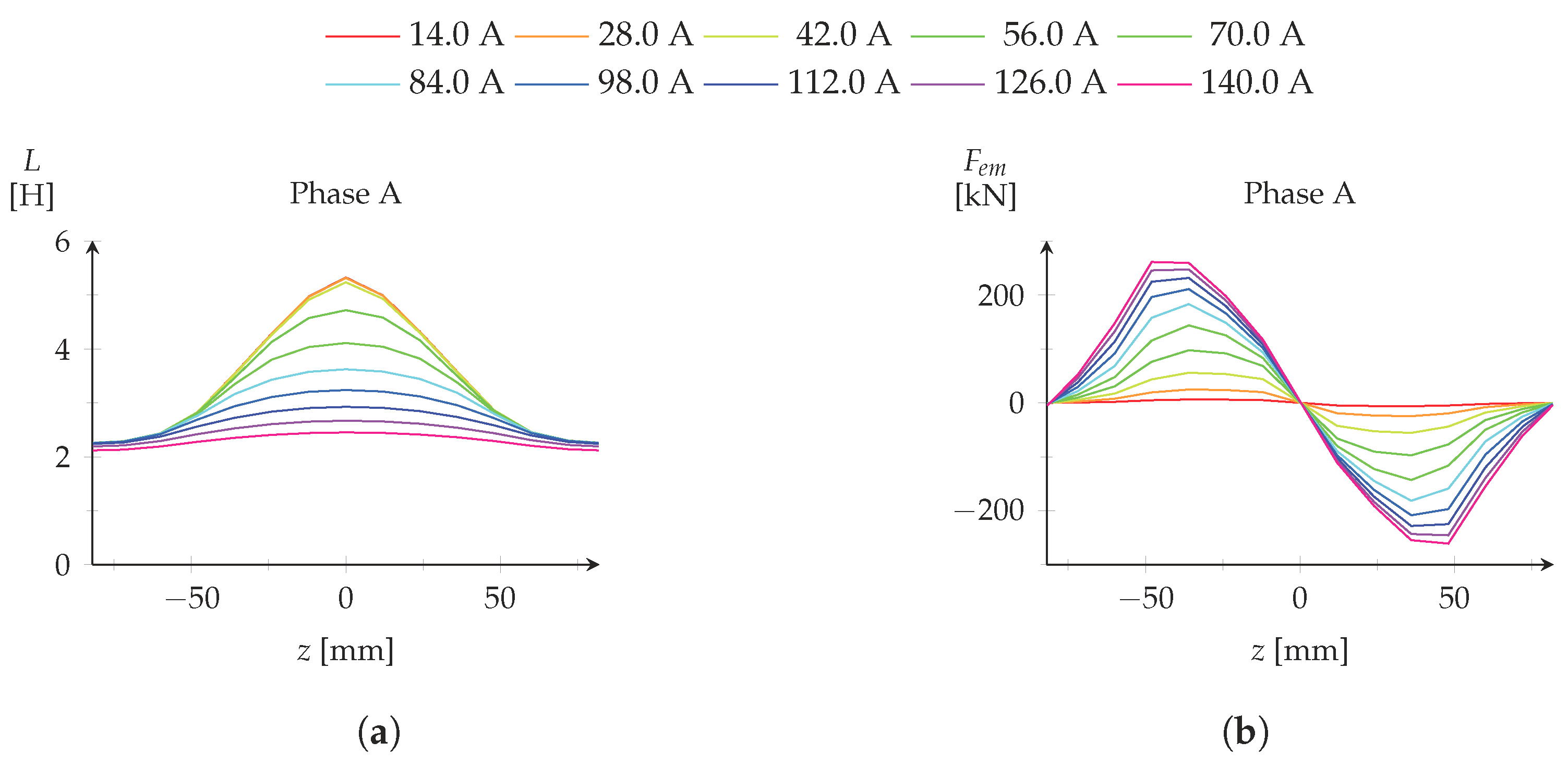
Table 1. The electromagnetic characteristics were computed with MagNet
®, a commercial software that uses the Finite Element Method (FEM) for electromagnetic analysis. The results, obtained from a 2D magneto-static analysis, are displayed in
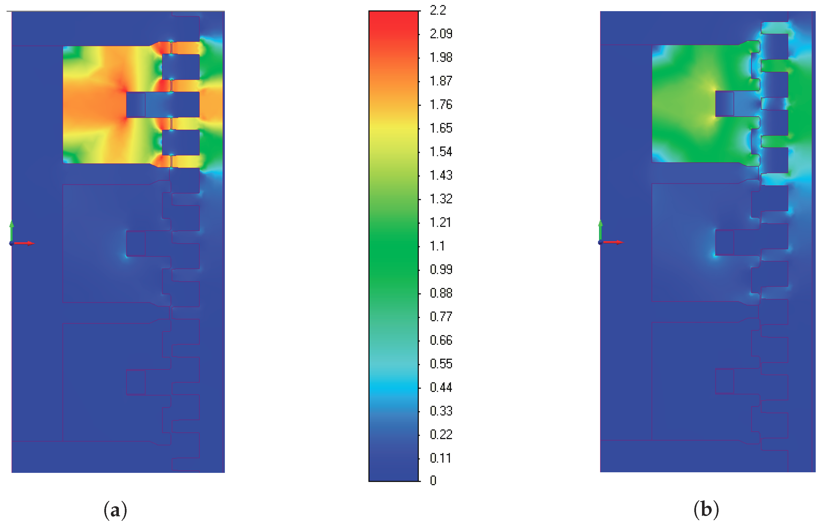
Figure 8. The magnetic flux density distribution for the alignment and non-alignment positions can be found in
Figure 9.
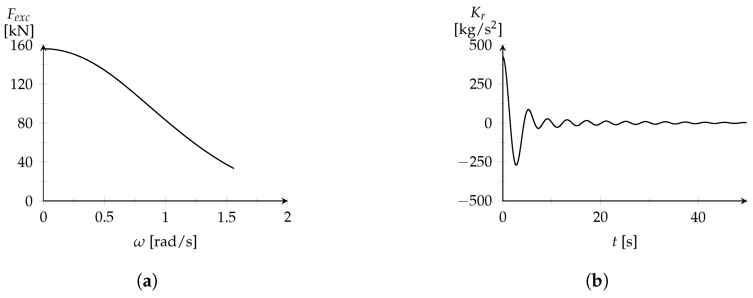
The hydrodynamic loads and the added mass were calculated in Nemoh, an open source software developed by Babarit and Delhommeau [
37] based on the Boundary Element Method (BEM). The obtained profiles for the excitation force and impulse response function can be observed in
Figure 10. The added mass results, as well as the dynamic properties of the oscillating body for the given regular wave, are presented in
Table 2.
The dynamic behavior of the TLSRG was evaluated for different velocities and reference current values, in order to identify the optimal control parameters. To accomplish this task, the Box Complex optimization method was applied following the same procedure described in [
38]. For each combination of velocity and current values, an optimization process was applied to the mathematical model of the TLSRG where the switching electric positions and the hysteresis band width were considered as optimization variables. In this process, the isolated DC/DC converter was omitted from the mathematical model and the generated electric power was directly delivered to a resistive load. For each evaluation, two simulations were always performed. The first was used to compute the electric load needed to consume the average electric generated power and the second to give the pretended data. A capacitance of 0.05 F was assumed for the capacitor in the converter and the initial bus voltage was defined as 6 kV. Each simulation time was set to 1 s.
For optimization purposes,
, the electric distance between
and
, was assumed as control variable and
was established as
. The control parameters
,
e
were optimized to achieve maximum electric power generation. The optimal results are displayed in
Figure 11. To obtain valid solutions for the electric positions, the following conditions were imposed:
The numerical limits for
and
were established as function of
by the relations defined below:
Knowing the optimal values for the hysteresis band and the electrical switching positions, the study of the TLSRG was redirected to the analysis of the TLSRG performance as PTO in a point absorber. The mathematical model described by Equation (
1) was implemented in Simulink
®. A value of 1025 kg/m
3 was assumed for the specific mass of sea water
and the drag coefficient
was established as 0.86. Since the natural frequency of the oscillating body is higher than the angular frequency of the excitation regular wave, the system cannot naturally achieve a resonant operation. Thus, the spring stiffness
was considered zero to not increase the difference between these oscillating frequencies. In the point absorber model, the optimal control parameters computed off-line are introduced with look-up tables and computed by linear interpolation. The ratio
was defined as 15 to provide a voltage of 400 V to the load when the DC bus is at 6 kV and the switching duty cycle
of the isolated DC/DC converter is 0.5. For the PI controller applied to the isolated DC/DC converter, the proportional gain
and integral gain
were tuned with the values 4954 and 494, respectively. The dynamic model was set to be simulated during the period of the considered regular wave.
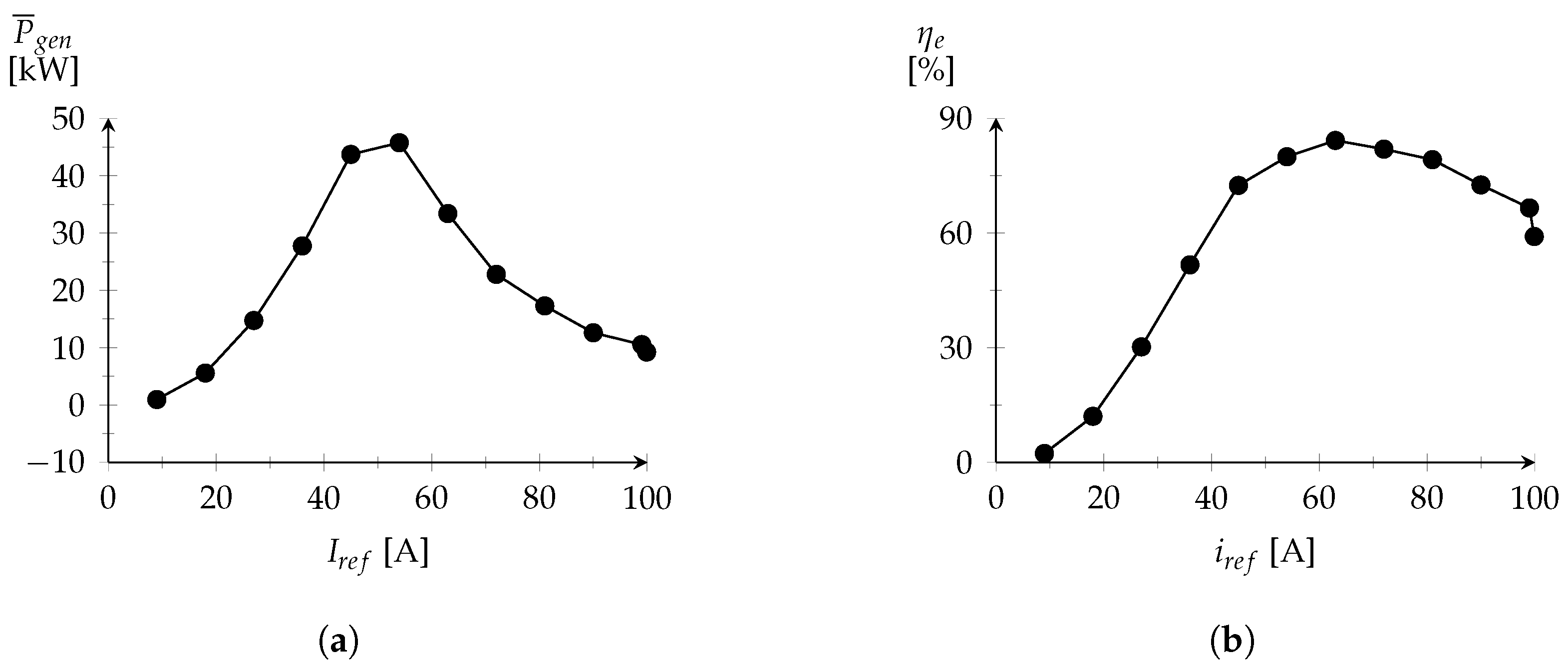
The performance of the conversion system was evaluated assuming a constant value for
and applying the proposed MPPT strategy. For the first case, the behavior of the system has been evaluated for 10 different values of
. The mean value of the generated electrical power
and the electric conversion efficiency
, for each value of
, are displayed in
Figure 12. For the second case, the system was subjected to an optimization process to search the optimal values of
and
for maximum electric power generation. The optimal value search was conducted by the Box Complex method, within the boundaries defined by 5 × 10
−3 s and 1 s for
, and defined by 1 × 10
−1 A and 7 A for
. As a result, the optimal values of 6.8 × 10
−2 s and 6.8 A were computed for
and
, respectively.
Table 3 presents the energetic conversion performance parameters of the system operating with the proposed MPPT control strategy and with the control at constant
. The latte is classified with the values obtained for the highest value of average generated electric power.
The excitation force profile adopted for each simulation can be observed in
Figure 13a. The
profile provided by the MPPT controller is exposed in
Figure 13b. The oscillating body absolute position and velocity are presented, respectively, in
Figure 14a,b for the operation with constant
and variable
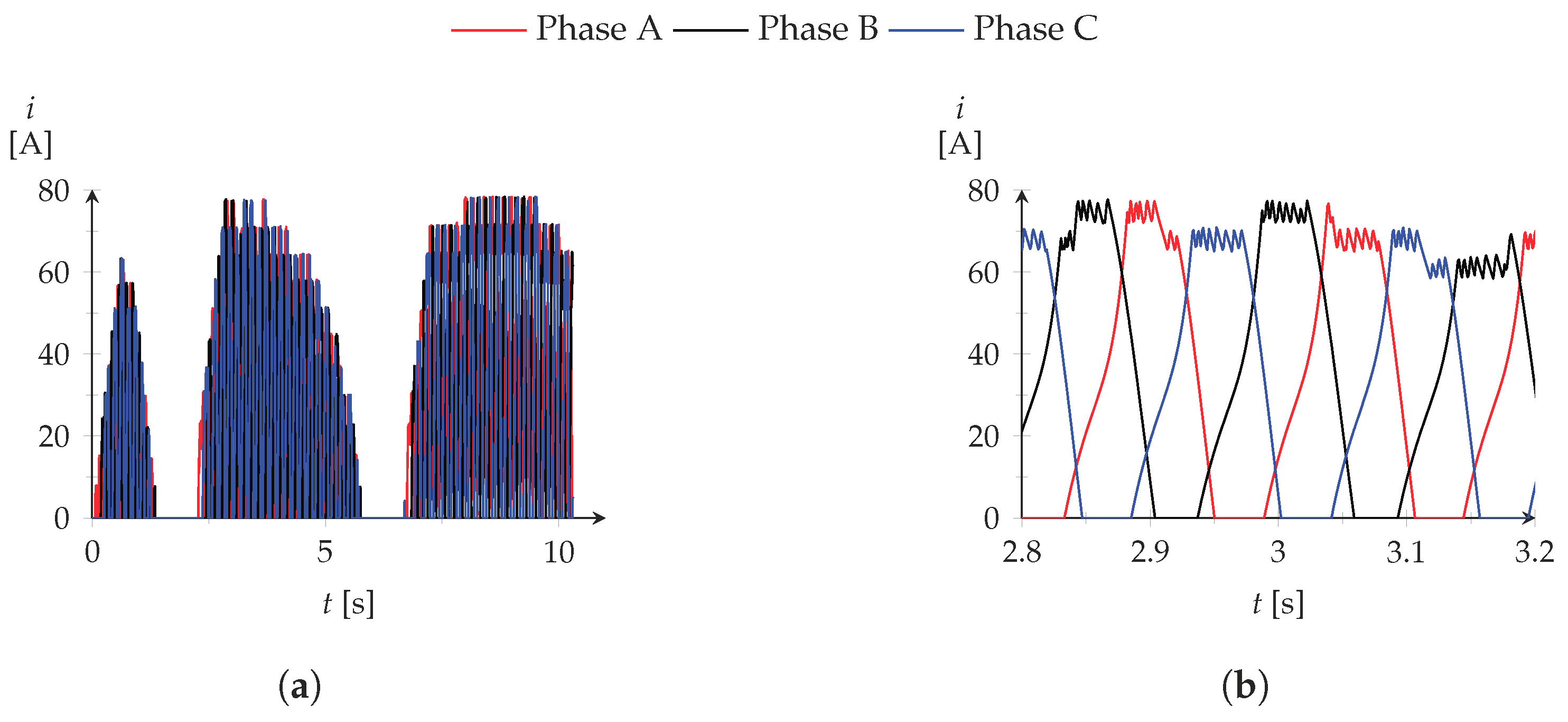
. The corresponding phase current intensity and electromechanical force are displayed, respectively, in
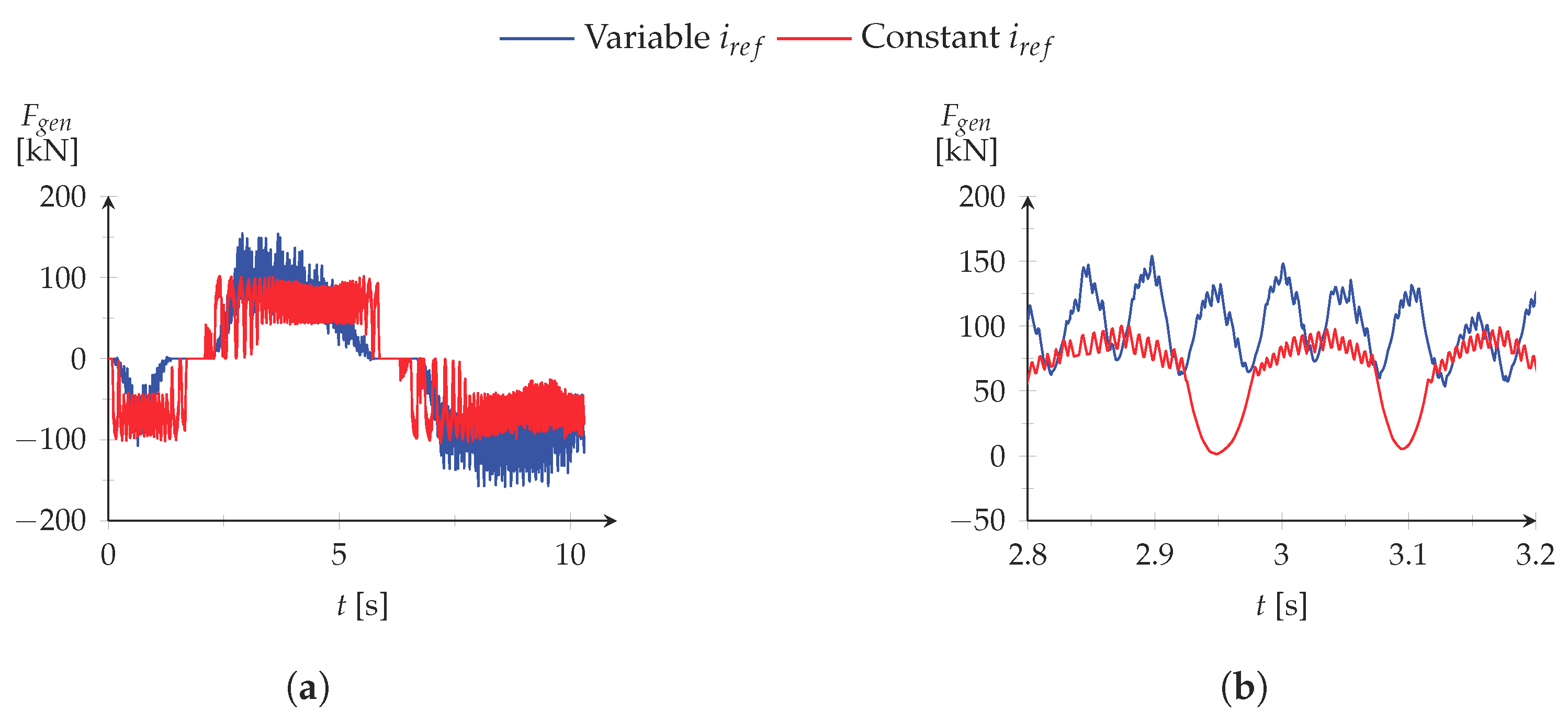
Figure 15 and
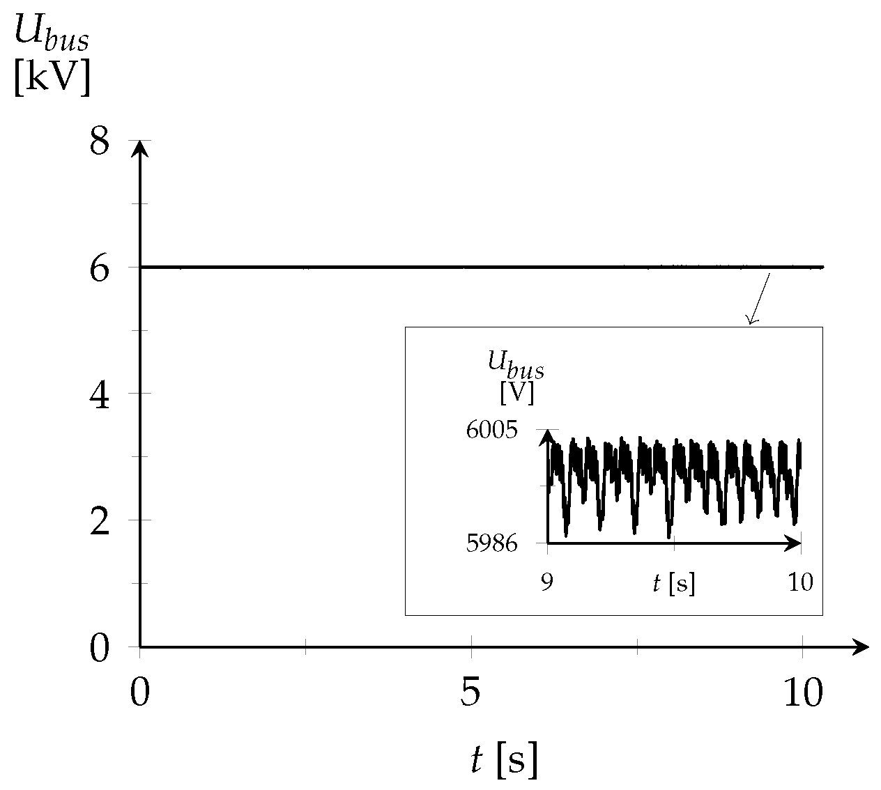
Figure 16. The DC bus voltage level is represented in
Figure 17.
From the simulations with constant current control, a better performance was verified for inferior values of , in respect to the maximum value specified. The best scenario was characterized with an average electric power of 45.7 kW for a reference current of 54 A. However, better performance was achieved with the proposed MPPT control strategy where 53.1 kW of average generated electric power was obtained with greater electric conversion efficiency.
While operating with a constant lower damping force, the system does not become over-damped when the wave loads are reduced and, as a consequence, the average mechanical power extracted may be increased. Although reduced, the generator force may still be excessive for some stages of the conversion cycle and not sufficient to extract the maximum available power when the wave excitation load reaches its peak value. Regulating the value of , these drawbacks are minimized since the damping of the TLSRG follows the excitation force induced by the wave with the goal to attain the maximum power generation conditions. However, for a variable , the electric phase current is also more irregular which increases the fluctuations of the TLSRG electromechanical force, when compared with a constant reference current control. Nevertheless, the fluctuations are not evident in the oscillating body displacement because of the attenuation provided by inertia of the moving system. The PI controller, applied to the isolated DC/DC converter, was also effective in maintaining the voltage level of the DC bus close to the respective nominal value. During the simulation period, a maximum voltage error of 0.22% was verified.


