Article

Comparison of the Stator Step Skewed Structures for Cogging Force Reduction of Linear Flux Switching Permanent Magnet Machines

1
College of Jincheng, Nanjing University of Aeronautics and Astronautics, Nanjing 211156, China
2
Department of Electrical Engineering, Nanjing University of Aeronautics and Astronautics, Nanjing 211106, China
*
Author to whom correspondence should be addressed.
Energies 2018, 11(8), 2172; https://doi.org/10.3390/en11082172
Submission received: 27 July 2018 / Revised: 15 August 2018 / Accepted: 18 August 2018 / Published: 20 August 2018
(This article belongs to the Section F: Electrical Engineering)

Abstract

:
Linear flux switching permanent magnetic (LFSPM) machines, with the armature windings and magnets both on the mover in addition to a robust stator, are a good choice for long stoke applications, however, a large cogging force is also inevitable due to the double salient structure, and will worsen the system performance. Skewing methods are always employed for the rotary machines to reduce the cogging torque, and the rotor step-skewed method is a low-cost approximation of regular skewing. The step skewed method can also be applied to the linear machines, namely, the stator step skewed. In this paper, three stator step skewed structures, which are a three-step skewed stator, a two-step skewed stator and an improved two-step skewed stator, are employed for the cogging force reduction of two types of LFSPM machines. The three structures are analyzed and compared with emphasize on the influence of the skewed displacement on the cogging force and the average thrust force. Based on finite element analysis (FEA), proper skewed displacements are selected according to maximum difference between the reduction ratio of the cogging force and the decrease ratio of the average thrust force, then, the corresponding results are compared, and finally, valuable conclusions are drawn according to the comparison. The comparison presented in this paper will be useful to the cogging force reduction of LFSPM machines in general.

1. Introduction

Linear electrical machines can directly drive linear motion without the need of any rotation to translation conversion equipment, such as gear boxes, chains, and screw couplings, thus they are widely used in various applications, from urban transit, manufacturing automation to direct-drive servo and other linear propulsion systems [1,2,3,4,5,6,7,8,9].
The linear induction motors (LIM) have simple structure, low cost and high reliability when used in high speed industrial transportation [1]. The linear switched reluctance motors (LSRM) can also be used as linear drives owing to several reasons, such as one side of the machine only has concentrated windings, while the other side is robust without any windings or permanent magnets (PM), low expected manufacturing expense and a good fault tolerance capability [4]. However, the above two kinds of linear motors have the drawbacks of low power density and efficiency. There has been increasing interest in the development of linear motors with higher power density and efficiency, therefore, linear permanent magnet synchronous motors (LPMSM) are becoming attractive candidate owing to the main benefits including the high power density and efficiency, good dynamic performance and simple structure [5]. However, compared with the LIM and LSRM, for the long stoke applications, whether the winding side or the PM side is placed on the long stator, the manufacturing and maintenance expense will significantly increase, besides, the demagnetization risk of PM will reduce system reliability. In recent years, linear flux switching permanent magnet (LFSPM) machine has become a competitive candidate for direct-drive systems owing to the following merits:
(1)
high power density that inherits from its rotary structure;
(2)
all the excitation sources like armature windings and PM are housed on the mover, easily achieving a simple thermal management;
(3)
A cost-effective stator of simple and robust.
Therefore, this kind of machine are suitable for a wide range of applications, especially for the long stator applications like transportation, elevator [6,7,8,9,10]. However, like the rotary flux switching permanent magnet (FSPM) machine, a considerable cogging force exists in the LFSPM machine due to the double salient structure, which causes periodic ripples of the thrust force and consequently worsen the performance of the machine. In general, the cogging force of the LFSPM machine is caused by both slot-effect and end-effect. Several efforts are made to reduce the cogging force of the LFSPM machine [9,10,11,12,13,14]. The end-effect component of the cogging force can be suppressed by the end assistant teeth [10,11,12]. The reduction methods of the slot-effect component of the cogging force utilize its periodic change characteristic, and are effective due to the suppression of the harmonic components of the cogging force [13]. A novel pseudo-six-phase LFSPM machine is proposed in [14]. The mover of this machine is separated into two independent parts with different phases, and the cogging force, especially the slot-effect component, can be reduced by a proper parameter design of the modules in the two parts. A complementary and modular LFSPM machine is investigated in [9]. This kind of machine can suppress the harmonics in the back electromotive force (back-EMF) and reduce the cogging force by design the flux barrier. However, the mover of the above two machines are complicated and will reduce the thrust force density due to the flux barrier. Due to the simple stator structure of the LFSPM machines, optimal stator design techniques are usually simple and cost effective. The optimization of the stator dimension is done in [9], and a suitable stator dimension is found by considering both cogging force and average thrust force. The cogging force reduction effect of the stator dimension optimization is limited, and should be combined with other methods. The slot-effect component of the cogging force is similar to the cogging torque in rotary PM machines, thus, can be reduced by similar techniques for the cogging torque reduction in rotary machines [15,16,17,18,19]. A rotor tooth-notching method is used in the rotary FSPM machine to reduce the cogging torque, and can be employed for the LFSPM machine, however, the reduction effect is also limited and not as good as that of the skewing method [15]. One of the most widely used methods for cogging toque reduction in rotary PM machines is the skewing method, and the step skewed structure, a low-cost approximation of regular skewing, is more practical [16,17,18,19]. A rotor step skewed method was investigated for rotary FSPM machines [17,18,19], and this method can be treated as several identical machines with shifted rotors axially conjoined together, and the cogging torque can be effectively reduced by carefully selecting the step skewed numbers and mechanical skewed angle. Additionally, the rotor skewing step number should be no more than three in order to simplify the implementation. The rotor step skewed methods can be transplant to LFSPM machines to diminish the cogging force, called the stator step skewed structure, and belong to the optimal stator design techniques. A staggered stator tooth structure is proposed for the C-core LFSPM machines [20,21], and this structure can effectively reduce the cogging force according to proper displacement design of the two stator parts. This method can be essentially treated as an improved two-step skewed stator structure, and is also useful for the conventional LFSPM machines. However, the skewing methods will reduce the thrust force or thrust force density, therefore, the selection of the skewed structure and corresponding skewed displacement should consider not only the cogging force but also the average thrust force.
Therefore, in this paper, three stator step-skewed structures—a three-step skewed stator, a two-step skewed stator and an improved two-step skewed stator—are analyzed and compared for the cogging reduction of a conventional LFSPM machine and a modular LFSPM machine. The comparison focuses on the influence of the skewed displacement on the cogging force and the average thrust force, the selection of the skewed displacement, the harmonics in back-EMF as well as the thrust force ripple. This paper is organized as follows: in Section 2, three stator step-skewed structures are introduced. Next, Section 3 compares the performance of the three stator step-skewed structures in detail and Section 4 analyzes the magnetic independence of the studied structures. Finally, conclusions are given in Section 5.

2. The Stator Step-Skewed Structures

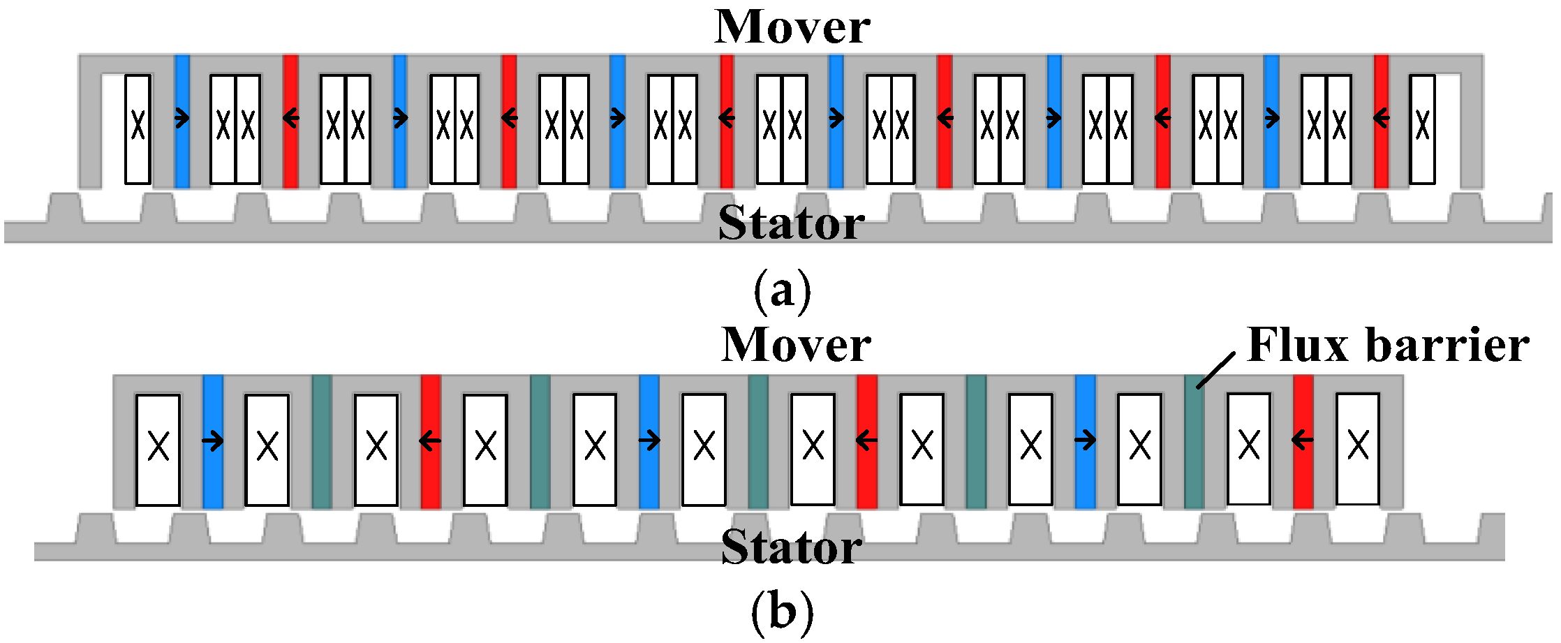
2.1. Original Topology

A conventional 12/14 LFSPM machine and a special LFSPM machine design, that is, a modular LFSPM (MLFSPM) machine, are employed as the original topology for the comparison of cogging force reduction methods, as shown in Figure 1, respectively. Additionally, Table 1 give the main design parameters for both machines.
When the mover passes each stator pole, the cogging force of the LFSPM machine varies periodically, and it can be expressed by a Fourier series expansion, which is:
F c o g = i = 1 F m i sin ( i x 2 π τ s + φ c i )
where Fmi and φci are the fundamental magnitude and phase angle of the ith harmonic component, respectively, x is the mover position, and τs is the stator pitch. The cogging forces of the two machines are shown in Figure 2a. It can be seen in Figure 2a, both machines are found to exhibit large cogging force, especially for the MLFSPM machine, the cogging force is too big for further application. Figure 2b shows the harmonic distribution of the cogging forces. Obviously, for both machine, the components over the seventh order are very small, and for the 12/14 LFSPM machine, the components of second, third and sixth are relatively large, while for the MLFSPM machine, the components of fundamental, second, third and sixth are relatively large.

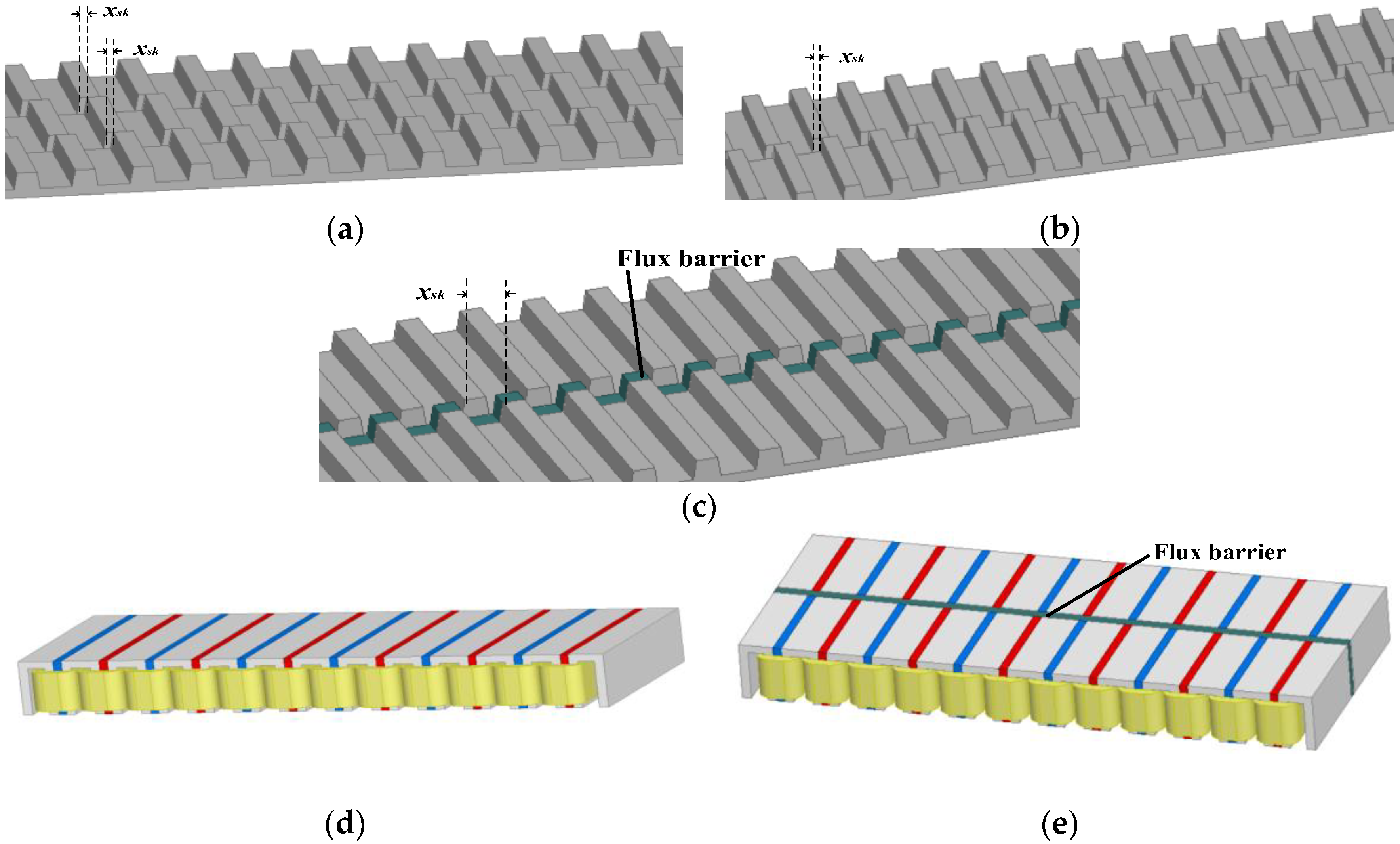
2.2. The Stator Step-Skewed Structures

As previously analyzed, both the 12/14 LFSPM machine and the MLFSPM machine exhibit big cogging force due to the double salient structure, which is the main component of the thrust force ripple. As one of the rotor skewing methods, the rotor step skewed technique can effectively reduce the cogging toruqe of rotary machines, and this technique can be also used for the cogging force reduction of linear machines, namely, stator step skewed structure. Therefore, for both LFSPM machines, three stator step skewed structures are employed for comparison, which are three-step skewed stator (SK3), two-step skewed stator (SK2) and an improved two-step skewed stator (ISK2), as shown in Figure 3a–c, respectively. As can be seen, the stators of SK3 and SK2 are arranged axially in three and two steps, respectively, while the stator of ISK2 is arranged axially in two steps with a flux barrier sandwiched between them. Next, two LFSPM machines with the above step-skewed sator structures are proposed and compared, the names of which are listed in Table 2.
The mover structures of 12/14 LFSPM-SK2 and 12/14 LFSPM-ISK2 machines are given in Figure 3d,e, for example, and while not shown, the 12/14 LFSPM-SK3, MLFSPM-SK3, MLFSPM-SK2 machines have similar mover structures with 12/14 LFSPM-SK2 machine, and MLFSPM-ISK2 machine has similar mover structure with 12/14 LFSPM-ISK2 machine. For the LFSPM machines with improved two-step skewed stator, as seen in Figure 3e, in order to reduce the cogging force and at the same time, to suppress the harmonics in PM flux-linkage, the mover is divided into two parts of same size, with a flux barrier at a depth of 5 mm between them, and the flux barrier is used to avoid a magnetic short circuit between the two mover parts. A front mover pole and a back mover pole with opposite magnetized magnets constitute one complete mover pole by sharing one armature coil. Correspondingly, a flux barrier is placed between the two step stator parts, as seen in Figure 3c [20,21].

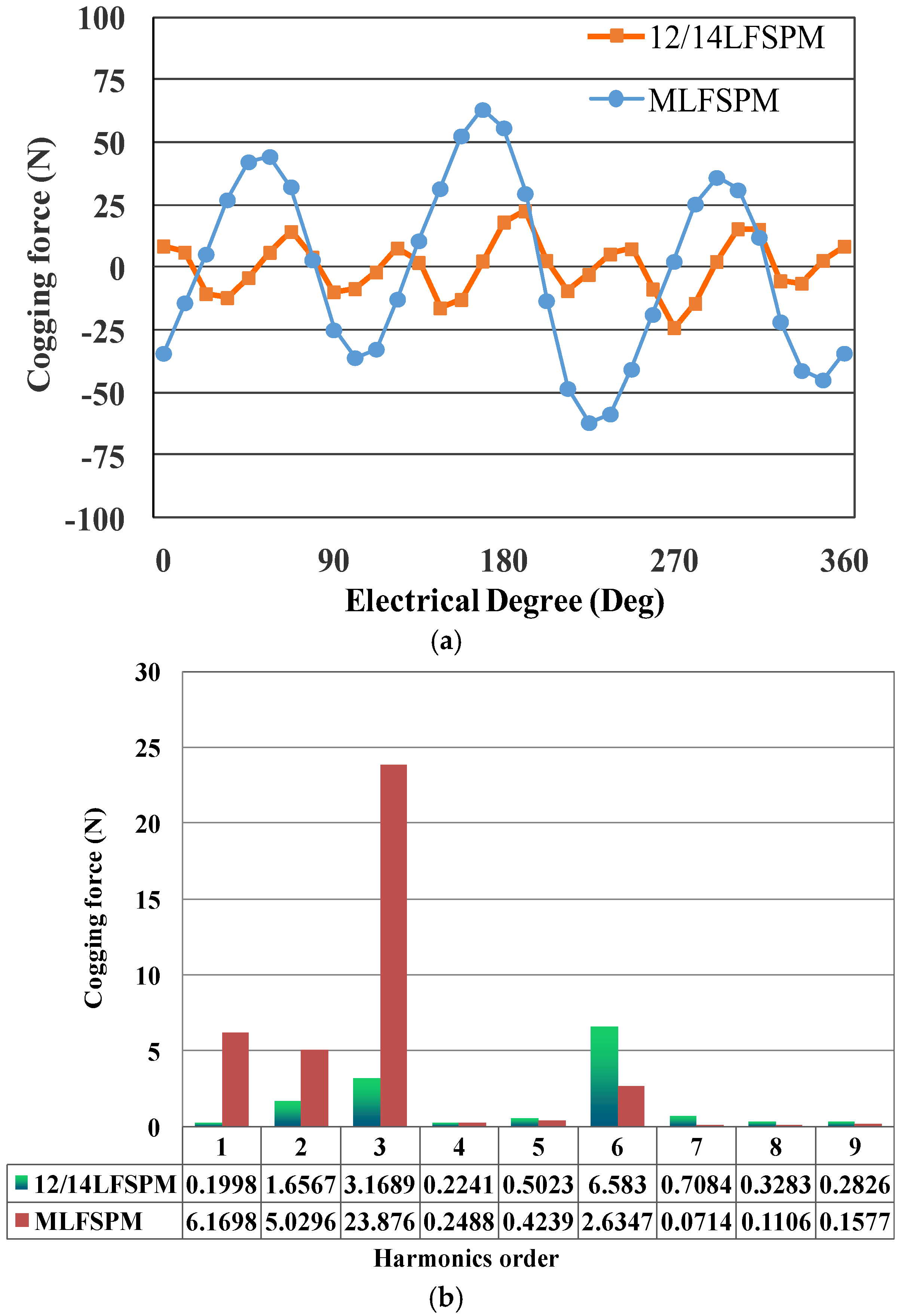
3. Comparison of Cogging Force Reduction

By neglecting the axial interactions between the steps, the machine cogging force under step skewed stator can be expressed as:
F c o g = k = 1 n F c o g k = i = 1 k = 1 n F m i k sin ( i x 2 π τ + φ c i k + i ( k 1 ) x s k 2 π τ )
Here, n is the number of skewed stator steps, and n = 2 for SK2 and ISK2, n = 3 for SK3, Fmik and φcik are the fundamental magnitude and phase angle of the ith harmonic component of kth skewed stator step, respectively, xsk is the skewed displacement of each step. It can be found that the combination of different n and xsk can be selected to reduce the cogging force, however, the average thrust force should be considered during the selection.
When Id = 0 control is employed, the average thrust force under d-q axes is:
F t = 3 2 v E I q
where E and Iq are the magnitude of the vectors of phase no-load back-EMF and q-axis current, respectively, and v is the machine velocity.
Figure 4 gives the vector diagrams of the LFSPM machine with and without step skewed stator, respectively. Here, θsk is electrical angle of xsk, E ˙ and E ˙ are vectors of the phase no-load back-EMF without and with step skewed stator, respectively, and δ is the angle between E ˙ and E ˙ , I ˙ q and I ˙ q are vectors of the q-axis current without and with step skewed stator, respectively, E ˙ s k is the vector of the phase no-load back-EMF corresponding to the kth skewed stator step, and E s k = 1 n E , where Esk and E are the magnitude of E ˙ s k and E ˙ , respectively, E ˙ s 1 has the same phase angle with that of E ˙ . In Figure 4a, E ˙ = E ˙ s 1 + E ˙ s 2 , and in Figure 4b, E ˙ = E ˙ s 1 + E ˙ s 2 + E ˙ s 3 . In Figure 4c, due to the magnets of the two mover parts of the LFSPM machine with improved two-step skewed stator are oppositely magnetized, E ˙ = E ˙ s 1 E ˙ s 2 .
According to Figure 4a, for the LFSPM machine with SK3, δ can be obtained as
δ = arctan sin 2 θ s k + sin θ s k 1 + cos 2 θ s k + cos θ s k
The magnitude of E ˙ can be expressed as
E = E sin 2 θ s k + sin θ s k 3 sin δ
Then, based on Equation (3)–(5), the following function can be achieved
f ( θ s k ) = E E = F t F t = sin 2 θ s k + sin θ s k 3 sin δ
where Ft and F t are the average thrust forces of the LFSPM machine without and with step skewed stator, respectively.
Similarly, according to Figure 4b, for the LFSPM machine with SK2, δ and f(θsk) are as follows:
δ = arctan sin θ s k 1 + cos θ s k
f ( θ s k ) = F t F t = sin θ s k 2 sin δ
According to Figure 4b, for the LFSPM machine ISK2, δ and f(θsk) are as follows
δ = arctan sin ( 180 ° θ s k ) 1 + cos ( 180 ° θ s k )
f ( θ s k ) = F t F t = sin ( 180 ° θ s k ) 2 sin δ
Based on above analysis, using finite element analysis (FEA) with ANSOFT Maxwell software 2D (2D FEA), proper θsk for the machines that listed in Table 2 are selected to achieve a relatively small cogging force by considering the average thrust force, as follows.
Figure 5 gives the variation of Δt and Δc with different θsk, where θsk = 0° is defined as the LFSPM machines without step skewed stator, Δt is the decrease ratio of the average thrust force, and Δ t = ( 1 f ( θ s k ) ) × 100 % ; Δc is the reduction ratio of peak to peak (p-p) cogging force, and Δ c = ( 1 F c p p F c p p ) × 100 % , here, F c p p and Fcp−p are the p-p cogging force with and without step skewed stator structure, respectively.
Both the cogging force and the average thrust force should be considered during the selection of θsk, therefore, the maximum difference between Δt and Δc can be used for selecting proper θsk, as shown in Figure 5. Then, proper values of θsk are obtained for above machines, as listed in Table 3. It can be found in Table 3, the 12/14 LFSPM machine under the three-step skewed stator with the skewed displacement of τ s 16 (12/14 LFSPM-SK3 machine) can significantly reduce the cogging force with 5% decrease of the average thrust force, while for the MLFSPM machine, the optimal structure is the improved two-step skewed stator with the skewed displacement of τ s 2 (MLFSPM-ISK2 machine), which can reduce the cogging force to its minimum without the average thrust force decrease.
Further, based on 2D FEA, Figure 6 shows the comparison of the harmonic distribution of cogging force of the LFSPM machines with and without step skewed stator, the 12/14 LFSPM-SK3 machine and the MLFSPM-ISK2 machine for example. It reveal that the 12/14 LFSPM-SK3 machine can significantly reduce both even and odd harmonics of the cogging force, and the MLFSPM-ISK2 machine can totally eliminate the odd harmonics of the cogging force.
In addition, the stator step skewed structures can also suppress the harmonics in the back-EMFs, which is also one of the reasons that cause thrust force ripple. Based on above selected θsk, the harmonic distribution of the no-load back-EMFs for the LFSPM machines are shown in Figure 7, and their total harmonic distortion (THDemf) are listed in Table 3. For the MLFSPM machine, due to the two coils of each phase have no complementary performance, the back-EMF is non-sinusoidal and exhibits relatively large amount of harmonics [22]. The ISK2 structure under θsk = 180° can achieve a complementary winding structure and eliminate the even harmonics of the back-EMFs.
Therefore, the thrust force of the LFSPM machines under selected θsk are shown in Figure 8 under 2D FEA, and σ, which is defined as the proportion of the p-p thrust force ripple to the average thrust force, is listed in Table 3. It can be found that, owing to the cogging force reduction and back-EMF harmonic suppression that based on the stator step skewed structures, the thrust force ripple of the original LFSPM machines are reduced greatly, especially for the 12/14 LFSPM-SK2 machine and the MLFSPM-ISK2 machine, the p-p thrust force ripples have been suppressed to 6.6% and 14% of the average thrust force, in addition to the decrease of the average thrust force by 4% and 0%, respectively. For comparison, σ under 3D FEA is also listed in Table 3, it shows that the 3D FEA results are generally higher than the 2D FEA ones.
It should be mentioned that, although the average thrust force of the MLFSPM-ISK2 machine does not decrease, the thrust force density decreases by 4.7% due to the addition of the flux barriers of 5mm depth between the two parts.

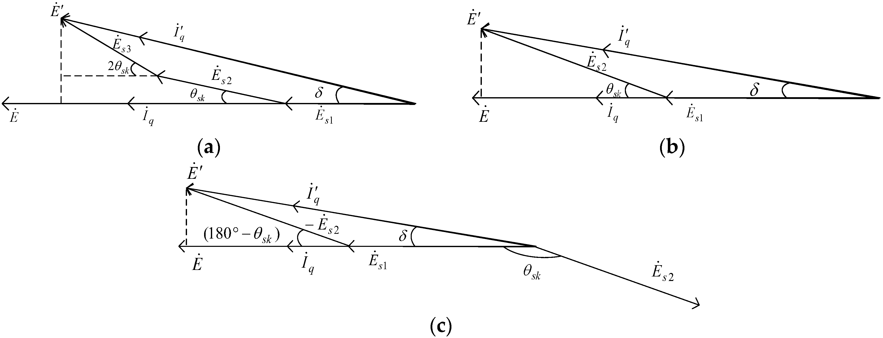
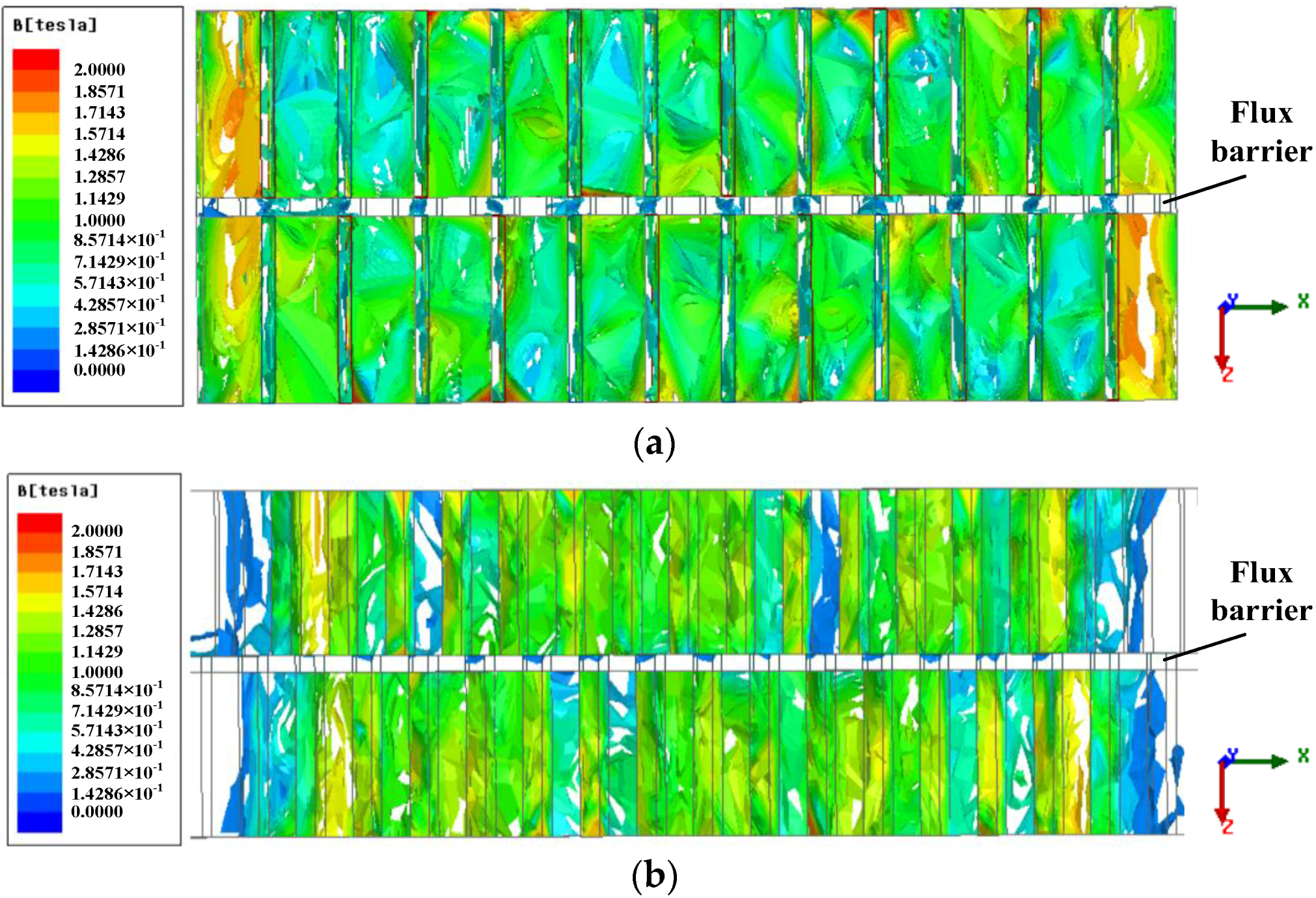
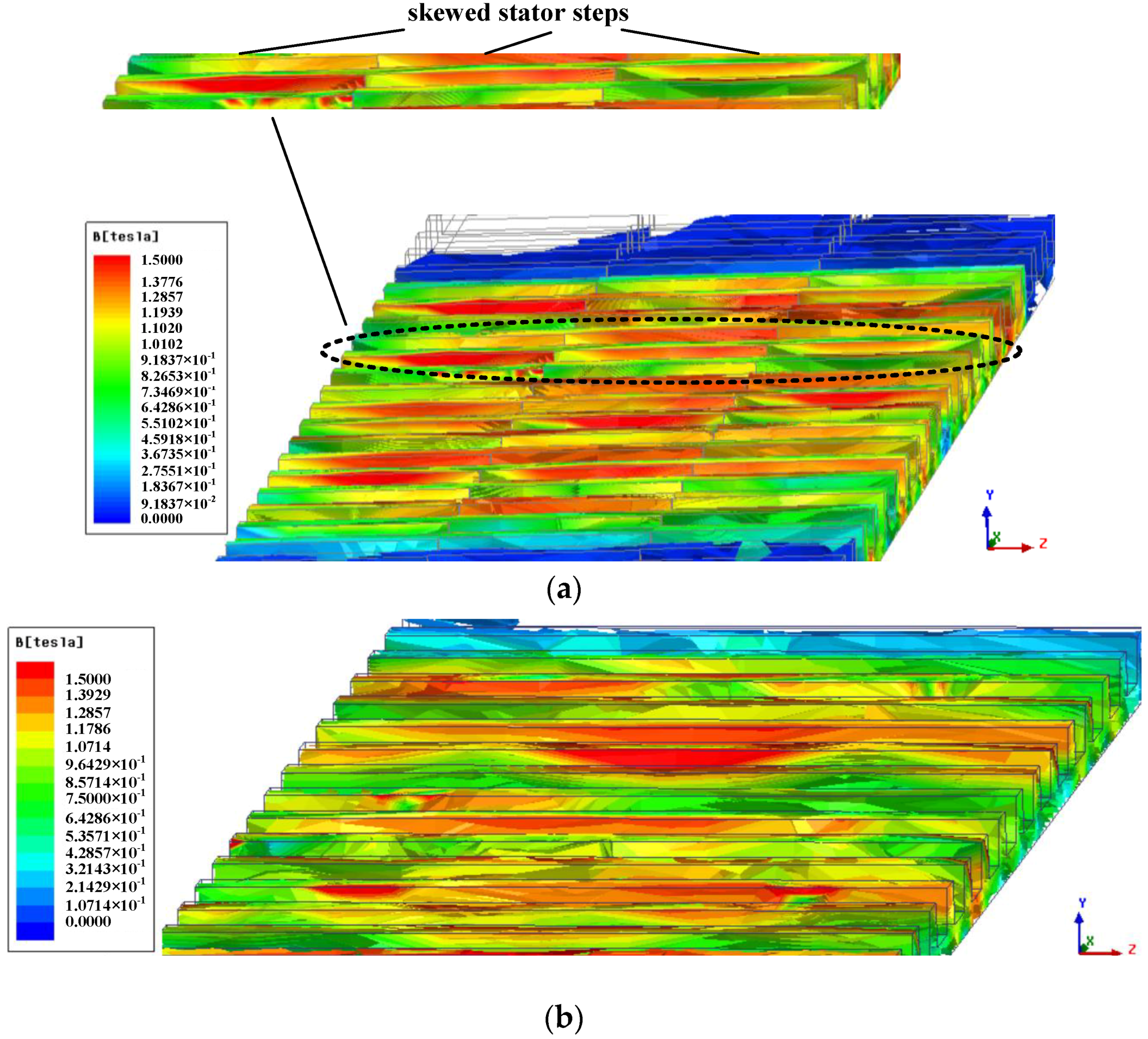
4. The Analysis of the Magnetic Independence

Due to the studied machines having a 3D structure, the 3D FEA is performed to analyze the magnetic independence, taking 12/14 LFSPM-ISK2 and 12/14 LFSPM-SK3 machines as examples. Figure 9a,b give the open-circuit flux density of the mover and the stator of the 12/14 LFSPM-ISK2 machine (top view) under 3D FEA, respectively. As can be seen, the employment of flux barriers isolate the magnetic circuits of the two mover parts and the two stator steps, indicating the two step skewed stator of 12/14 LFSPM-ISK2 machine has good mutual magnetic independence.
For 12/14 LFSPM-SK3 machine, the open-circuit flux density of the stator is demonstrated by in Figure 10a, in addition, the open-circuit flux density of the stator of the 12/14 LFSPM machine is given in Figure 10b for comparison. As can be seen, compared with the stator flux density of the 12/14 LFSPM machine, the flux density of three skewed stator steps of the 12/14 LFSPM-SK3 machine are different from each other. Therefore, although the three skewed stator steps of the 12/14 LFSPM-SK3 machine is not isolated by flux barriers, the magnetic circuits of the three skewed stator steps can be approximately treated as independent.
Figure 11 shows the phase A no-load back-EMF for the 12/14 LFSPM, 12/14 LFSPM-ISK2 and 12/14 LFSPM-SK3 under 2D FEA and 3D FEA, respectively. It is worth noting that the magnitude of the no-load back-EMF of 3D FEA is a little smaller than that of 2D FEA. It can be found that the results are in good agreement under 2D FEA and 3D FEA.

5. Conclusions

The performance of the LFSPM machines is always affected by the big cogging force. The analyses and comparison of the three stator step skewed structures in this paper for the cogging reduction of LFSPM machines are useful and practical. The following conclusions can be reached:
(1)
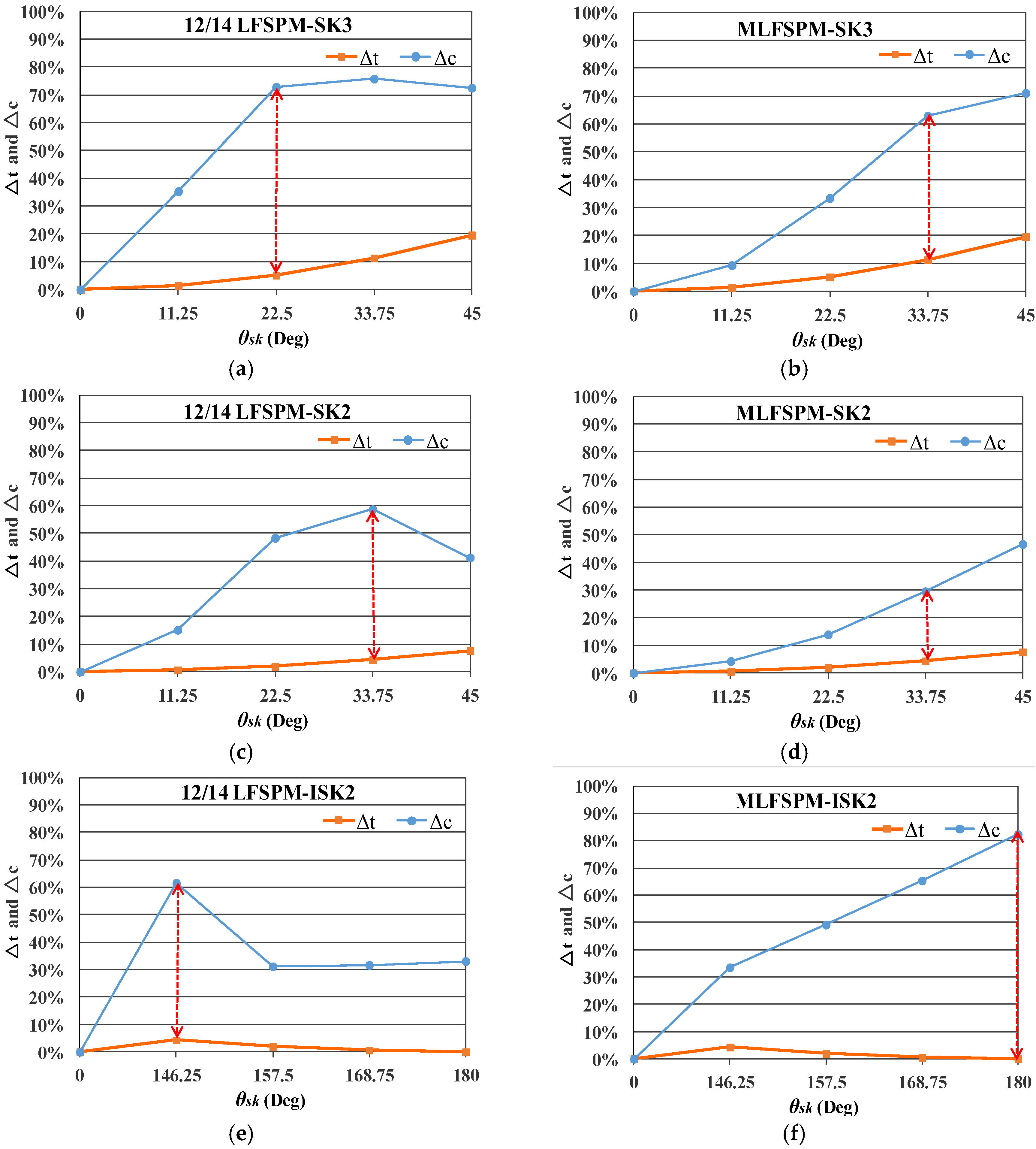
The step skewed stator is an effective structure to reduce the cogging force, however, the selection of the step skewed structure and corresponding skewed displacement impacts greatly on both the cogging force and average thrust force.
(2)
For the stator step skewed structures, the skewed displacement can be selected according to maximum difference between the reduction ratio of the cogging force and the decrease ratio of the average thrust force.
(3)
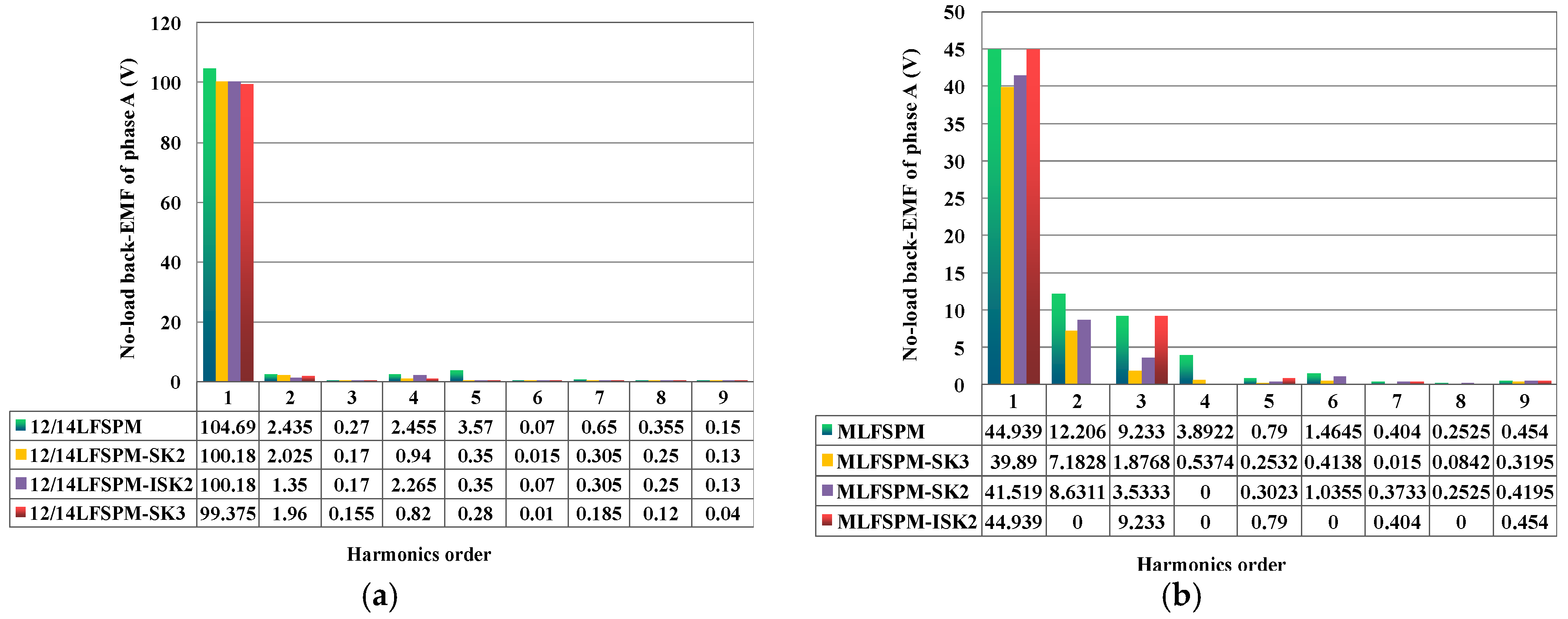
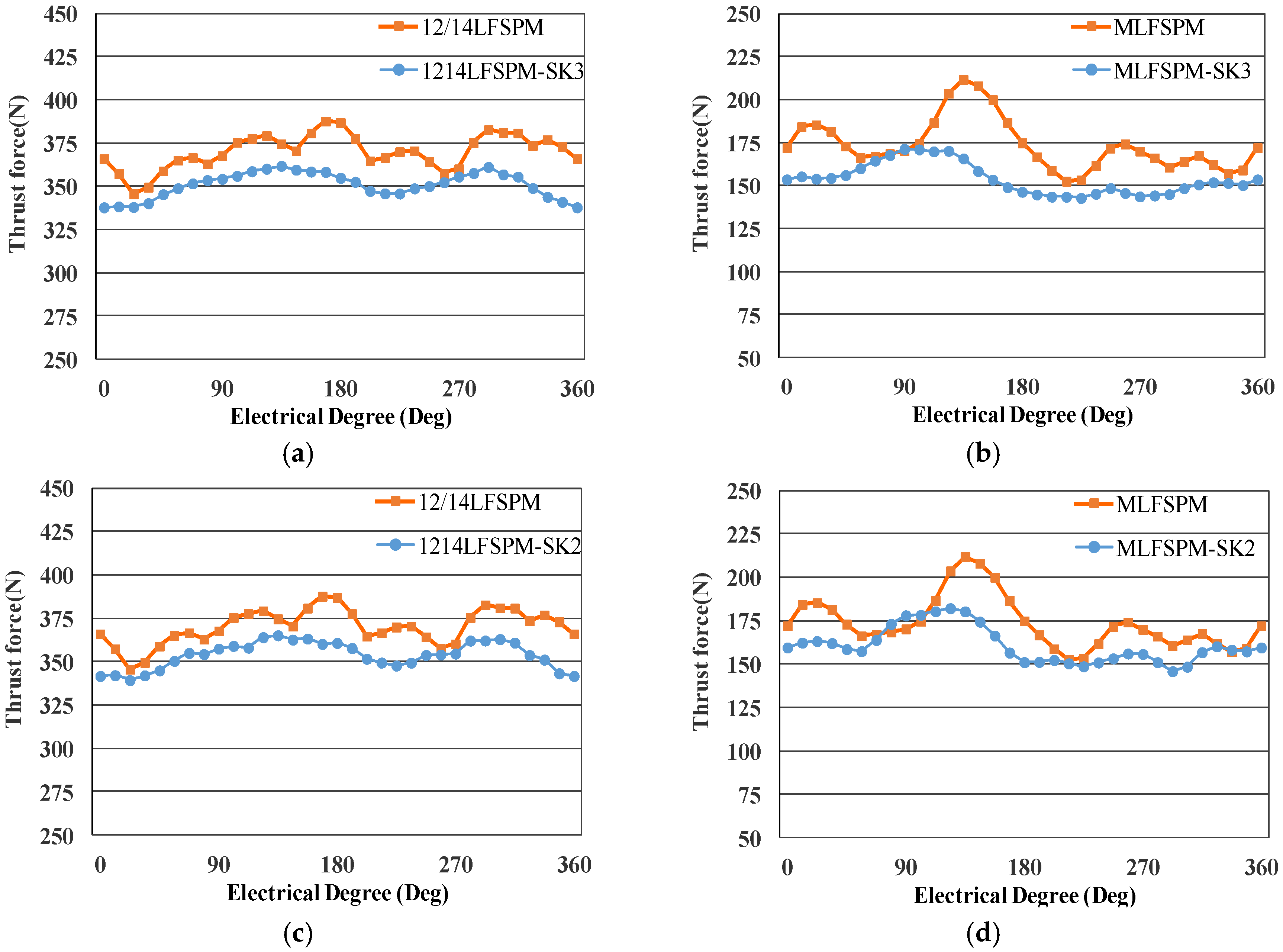
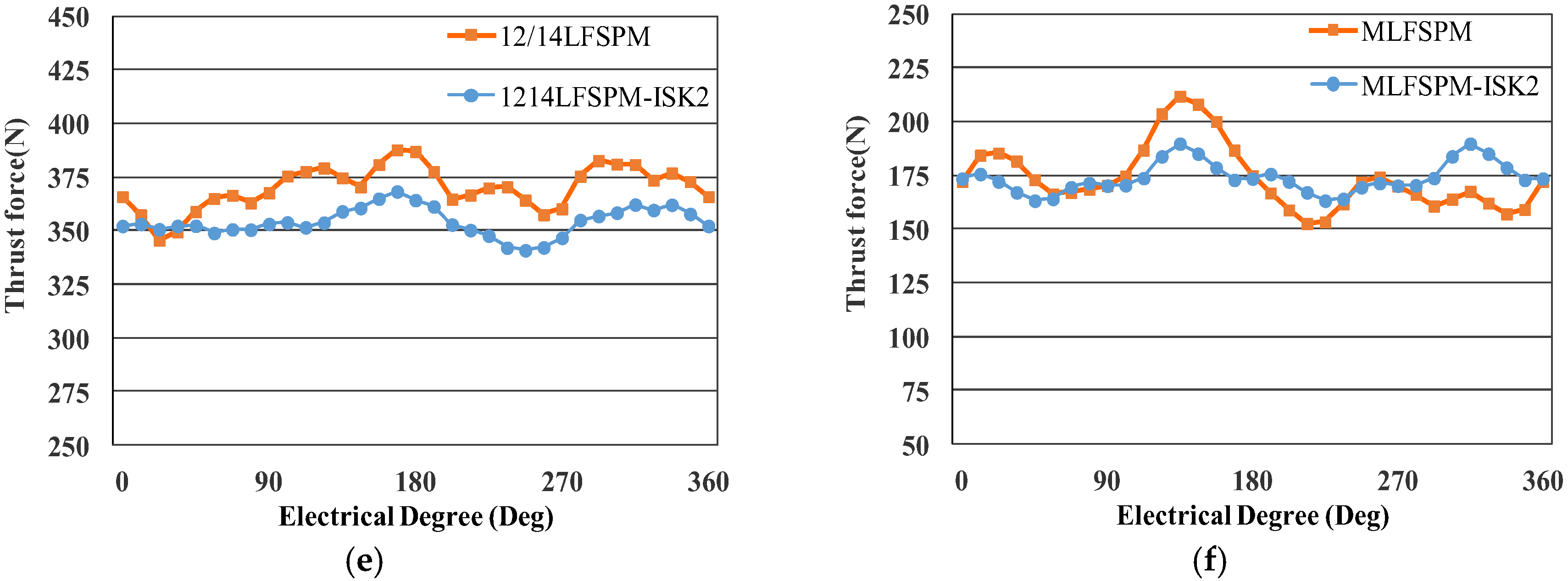
The harmonics in the no-load back-EMF can also be suppressed by the step skewed structures, and based on the reduction of the cogging force and suppression of the harmonics in the no-load back-EMF, the thrust force ripple is significantly reduced by the stator step skewed structures with a small drop of the thrust force density.
(4)
All the stator step skewed structures are general, practical, and can be applied for the cogging force reduction of conventional LFSPM machines and LFSPM machines with special design like modular structure, C-core, E-core structures and so on.
(5)
Compared with the stator of the original structure that made from a single segment, the skewed stator is made from segments that arranged axially with a skewed displacement, decreasing the robustness of the stator. In addition, because of the flux barrier, the robustness of the 12/14 LFSPM machines with ISK2 stator is lower than that of the 12/14 LFSPM machines with SK3 and SK2 stators.

Author Contributions

W.J.H. is the main author, and gave the ideas as well as carried the analysis. Y.W. gave some useful suggestions in the construction of this paper and performed parts of the calculation. All the authors have contributed significantly to this work.

Funding

This work was supported in part by the Chinese National Science Foundation under Project 51407090 and Project 51741705, the Power Electronics Science and Education Development of Delta Group under Project DREG2018014, the Fundamental Research Funds for Central University under Project 1003-XAC18083 and Project 1003-XCA18154-04, the Research Founds of College of Jincheng under Project 2007-y-02.

Acknowledgments

We would like to thank Hui Liu for the help in the 3D FEA.

Conflicts of Interest

The authors declare no conflict of interest.

References

  1. Musolino, A.; Rizzo, R.; Tripodi, E. The double-sided tubular linear induction motor and its possible use in the electromagnetic aircraft launch system. IEEE Trans. Plasma Sci. 2013, 41, 1193–1200. [Google Scholar] [CrossRef]
  2. Kim, Y.K.; Gu, B.G.; Jung, I.S.; Won, S.H.; Hur, J. Analysis and Design of Slotted Tubular Linear Actuator for the Eco-pedal System of a Vehicle. IEEE Trans. Magn. 2012, 48, 939–942. [Google Scholar] [CrossRef]
  3. Wai, R.J.; Lee, J.D.; Chuang, K.L. Real-time PID control strategy for Maglev transportation system via particle swarm optimization. IEEE Trans. Ind. Electron. 2011, 58, 629–646. [Google Scholar] [CrossRef]
  4. Amoros, J.G.; Andrada, P. Sensitivity Analysis of Geometrical Parameters on a Double-Sided Linear Switched Reluctance Motor. IEEE Trans. Ind. Electron. 2010, 57, 311–319. [Google Scholar] [Green Version]
  5. Lin, F.J.; Shen, P.H.; Yang, S.L.; Chou, P.H. Recurrent radial basis function network-based fuzzy neural network control for permanent magnet linear synchronous motor servo drive. IEEE Trans. Magn. 2006, 42, 3694–3705. [Google Scholar] [CrossRef]
  6. Zhu, Z.Q.; Chen, X.; Chen, J.T.; Howe, D.; Dai, J.S. Novel linear flux-switching permanent magnet machines. In Proceedings of the 2008 IEEE International Conference on Electrical Machines and Systems (ICEMS), Wuhan, China, 17–20 October 2008; pp. 2948–2953. [Google Scholar]
  7. Min, W.; Chen, J.T.; Zhu, Z.Q.; Zhu, Y.; Duan, G.H. Optimization of linear flux switching permanent magnet motor. In Proceedings of the 2010 IEEE Vehicle Power and Propulsion Conference (VPPC), Lille, France, 1–3 September 2010; pp. 1–6. [Google Scholar]
  8. Krop, D.; Encica, L.; Lomonova, E. Analysis of a novel double sided flux switching linear motor topology. In Proceedings of the XIX International Conference on Electrical Machines (ICEM), Rome, Italy, 6–8 September 2010; pp. 1–5. [Google Scholar]
  9. Cao, R.W.; Cheng, M.; Chris, M.; Hua, W.; Wang, X.; Zhao, W.X. Comparison of Complementary and Modular Linear Flux-Switching Motors with Different Mover and Stator Pole Pitch. IEEE Trans. Magn. 2013, 49, 1493–1504. [Google Scholar] [CrossRef]
  10. Wang, C.F.; Shen, J.X.; Wang, Y. A new method for reduction of detent force in permanent magnet flux-switching linear motors. IEEE Trans. Magn. 2009, 45, 2843–2846. [Google Scholar] [CrossRef]
  11. Min, W.; Chen, J.T.; Zhu, Z.Q.; Zhu, Y.; Zhang, M.; Duan, G.H. Optimization and comparison of novel e-core and c-core linear switched flux PM machines. IEEE Trans. Magn. 2011, 47, 2134–2141. [Google Scholar] [CrossRef]
  12. Du, Y.; Yang, G.; Quan, L.; Zhu, X.Y.; Xiao, F.; Wu, H.Y. Detent force reduction of a C-core linear flux-switching permanent magnet machine with multiple additional teeth. Energies 2017, 10, 318. [Google Scholar] [CrossRef]
  13. Zhou, S.G.; Yu, H.T.; Hu, M.Q.; Jiang, C.X.; Hao, L. Reduction of Cogging Force in a Linear Flux-Switching Permanent-Magnet Brushless AC Machine for Direct-Drive Applications. IEEE Trans. Magn. 2011, 47, 3252–3255. [Google Scholar] [CrossRef]
  14. Zhong, W.; Yu, H.; Hu, M.; Shi, Z.; Liu, Q. Study on a Novel Pseudo-Six-Phase Linear Flux-Switching Permanent-Magnet Machine for Direct Drive. IEEE Trans. Appl. Supercond. 2016, 26, 1–4. [Google Scholar] [CrossRef]
  15. Jin, M.J.; Wang, Y.; Shen, J.X.; Luk, P.C.K.; Fei, W.Z.; Wang, C.F. Cogging torque suppression in a permanent magnet flux-switching integrated-starter-generator. IET Electr. Power Appl. 2010, 4, 647–656. [Google Scholar] [CrossRef] [Green Version]
  16. Wang, Y.; Jin, M.J.; Fei, W.; Shen, J.X. Cogging torque reduction in PM flux-switching machines by rotor teeth axial pairing. IET Electr. Power Appl. 2010, 4, 500–506. [Google Scholar] [CrossRef]
  17. Liu, X.D.; Gu, Z.X.; Zhao, J. Torque Ripple Reduction of a Novel Modular Arc-Linear Flux-Switching Permanent-Magnet Motor with Rotor Step Skewing. Energies 2016, 9, 404. [Google Scholar] [CrossRef]
  18. Fei, W.; Luk, P.C.K.; Shen, J. Torque analysis of permanentmagnet flux switching machines with rotor step skewing. IEEE Trans. Magn. 2012, 48, 2664–2673. [Google Scholar] [CrossRef] [Green Version]
  19. Zhu, Z.Q.; Zhou, Y.J. Torque Density and Magnet Usage Efficiency Enhancement of Sandwiched Switched Flux Permanent Magnet Machines Using V-Shaped Magnets. IEEE Trans. Magn. 2013, 49, 3834–3837. [Google Scholar] [CrossRef]
  20. Hao, W.J.; Wang, Y. Thrust Force Enhancement and Ripple Reduction of A Sandwiched Linear Flux Switching Permanent Magnet Machine with Segment Stator for Urban Rail Transit. IEEJ Trans. Electr. Electron. Eng. 2018, 13, 924–931. [Google Scholar] [CrossRef]
  21. Hao, W.J.; Wang, Y. Thrust Force Ripple reduction of two C-core Linear Flux-Switching Permanent Magnet Machines of High Thrust Force Capability. Energies 2017, 10, 1608. [Google Scholar] [CrossRef]
  22. Cao, R.W.; Cheng, M.; Hua, W. Investigation and General Design Principle of a New Series of Complementary and Modular Linear FSPM Motors. IEEE Trans. Ind. Electron. 2013, 60, 5436–5446. [Google Scholar] [CrossRef]
Figure 1. Machine original topology: (a) 12/14 linear flux switching permanent magnet (LFSPM) machine; (b) modular LFSPM (MLFSPM) machine.
Energies 11 02172 g001
Figure 2. Cogging force of the two LFSPM machines: (a) cogging force waveform; (b) harmonic distribution.
Energies 11 02172 g002
Figure 3. Structures of the LFSPM machine with step skewed stator: (a) three-step skewed stator (SK3); (b) two-step skewed stator (SK2); (c) improved two-step skewed stator (ISK2); (d) mover structure of 12/14 LFSPM-SK2; (e) mover structure of 12/14 LFSPM-ISK2.
Energies 11 02172 g003
Figure 4. The vector diagrams of the LFSPM machine with and without step skewed stator: (a) LFSPM machine with and without SK3; (b) LFSPM machine with and without SK2; (c) LFSPM machine with and without ISK2.
Energies 11 02172 g004
Figure 5. The variation of Δt and Δc with different θsk for: (a) 12/14 LFSPM-SK3 machine; (b) MLFSPM-SK3 machine; (c) 12/14 LFSPM-SK2machine; (d) MLFSPM-SK2 machine; (e) 12/14LFSPM-ISK2 machine; (f) MLFSPM-ISK2 machine.
Energies 11 02172 g005
Figure 6. The harmonic distribution comparison of cogging force for: (a) 12/14 LFSPM machines; (b) MLFSPM machines.
Energies 11 02172 g006
Figure 7. The harmonic distribution of the no-load back-EMFs for: (a) 12/14 LFSPM machines; (b) MLFSPM machines.
Energies 11 02172 g007
Figure 8. The thrust force comparison for: (a) 12/14 LFSPM-SK3 machine; (b) MLFSPM-SK3 machine; (c) 12/14 LFSPM-SK2machine; (d) MLFSPM-SK2 machine; (e) 12/14LFSPM-ISK2 machine; (f) MLFSPM-ISK2 machine.
Energies 11 02172 g008aEnergies 11 02172 g008b
Figure 9. Open-circuit flux density of the mover and the stator of the 12/14 LFSPM-ISK2 machine (top view) under 3D FEA: (a) mover; (b) stator.
Energies 11 02172 g009
Figure 10. Open-circuit flux density of the stator under 3D FEA for: (a) the 12/14 LFSPM-SK3 machine; (b) 12/14 LFSPM machine.
Energies 11 02172 g010
Figure 11. The back-EMF comparison under: (a) 2D FEA; (b) 3D FEA.
Energies 11 02172 g011
Table 1. Main design parameters.
Item and Symbol12/14 LFSPMModular LFSPM (MLFSPM)
Air gap length, g (mm)11
Total height, ht (mm)3838
Machine depth, D (mm)8080
Mover slot pith, tms (mm)2020
PM/Flux barrier thickness, wpm (mm)3.53.5
Mover tooth width, wmt (mm)44
Stator pole width, wst (mm)5.85.8
Stator pole pith, ts (mm)17.1417.14
Magnet remanence, Br (T)1.21.2
Number of phases33
Armature windings per phase200 turns200 turns
Rated current amplitude, INm (A)1010
Rated power, PN (KW)1.480.7
Rated force, FN (N)370175
Velocity4 m/s4 m/s
Table 2. Structures and names.
StructureName
12/14 LFSPM with three-step skewed stator12/14 LFSPM-SK3
12/14 LFSPM with two-step skewed stator12/14 LFSPM-SK2
12/14 LFSPM with improved two-step skewed stator12/14 LFSPM-ISK2
MLFSPM with three-step skewed statorMLFSPM-SK3
MLFSPM with two-step skewed statorMLFSPM-SK2
MLFSPM with improved two-step skewed statorMLFSPM-ISK2
Table 3. Selected θsk and comparison results for LFSPM machines with skewed stator.
StructureθskxskΔtΔcTHDemfσ 2D FEAσ 3D FEA
12/14 LFSPM00%100%4.8%11.4%14.1%
12/14 LFSPM-SK322.5° τ s 16 5%73%2.2%6.8%8.9%
12/14 LFSPM-SK233.75° 3 τ s 32 4%59%2.3%6.6%8.3%
12/14 LFSPM-ISK2146.25° 13 τ s 32 4%62%2.7%7.7%10%
MLFSPM00%100%35%34%35.7%
MLFSPM-SK333.75° 3 τ s 32 11%63%18%18%18.2%
MLFSPM-SK245° τ s 8 8%47%22%22%23.1%
MLFSPM-ISK2180° τ s 2 0%82%18%14%16.7%

