Article

PLL-Less Three-Phase Four-Wire SAPF with STF-dq0 Technique for Harmonics Mitigation under Distorted Supply Voltage and Unbalanced Load Conditions

by
Yap Hoon
1,2,* and
Mohd Amran Mohd Radzi
1,2
1
Department of Electrical and Electronic Engineering, Faculty of Engineering, Universiti Putra Malaysia, Serdang 43400, Selangor, Malaysia
2
Centre for Advanced Power and Energy Research (CAPER), Faculty of Engineering, Universiti Putra Malaysia, Serdang 43400, Selangor, Malaysia
*
Author to whom correspondence should be addressed.
Energies 2018, 11(8), 2143; https://doi.org/10.3390/en11082143
Submission received: 29 June 2018 / Revised: 11 July 2018 / Accepted: 20 July 2018 / Published: 17 August 2018

Abstract

:
This paper presents a non-iterative technique that generates reference current to manage operation of a three-phase four-wire shunt active power filter which employs a three-leg split capacitor voltage source inverter (VSI) topology. The proposed technique integrates together a self-tuning-filter (STF) and direct-quadrature-zero (dq0) principle (referred here as STF-dq0), allowing the controlled shunt active power filter (SAPF) to perform effectively under distorted source voltages and unbalanced load conditions. Unlike the previous technique developed based on the standard dq0 principle, the proposed technique does not require any service from a phase-locked loop (PLL) where two STFs are applied to separate harmonic and fundamental elements for the purpose of generating synchronization phases and reference current, respectively. Simulation work which includes connection of the SAPF circuits, design of control techniques and all the necessary assessments are conducted in MATLAB-Simulink platform. Performance achieved by the SAPF while utilizing the proposed technique is thoroughly investigated and benchmarked with that demonstrated by the SAPF while using the standard dq0 technique, to evaluate the inherent advantages. Exhaustive simulation results are provided and thoroughly discussed to support design concept, effectiveness, and benefits of the proposed technique.

1. Introduction

Ensuring good quality of power supply is often a challenging task due to ever-increasing usage of power electronics products. These products, which are more commonly known as nonlinear loads, draw non-sinusoidal currents and reactive power from the connected power system, and cause high harmonic distortion (indicated by total harmonic distortion (THD) values) in the source current and deteriorate overall power system efficiency (indicated by power factor). Moreover, in three-phase four-wire system, connection of single-phase loads and unequal loads distribution across the three phases causes excessive neutral currents. These power quality issues can partially be solved by applying passive filter. The viable solution is by using active power filter (APF) connected in parallel to the polluted power system. APFs that are applied in this manner are called the shunt-typed. The good thing about shunt active power filters (SAPFs) is that they are able to deal with unbalanced issues in the source current along with mitigating harmonic current and compensating reactive power.
For application in three-phase four-wire system, SAPFs are available in two basic topologies. First, three-leg split capacitor topology where the middle-point of its dc-link is connected to the neutral wire of the power system [1]. Second, four-leg topology which is a more complex topology due to higher number of semiconductor switches employed and an additional control input [2]. In this work, the split capacitor topology is preferred for its less complicated structure. Its connection path to the neutral wire allows the excessive neutral currents to flow towards the two dc-link capacitors where they will be absorbed and eventually be removed from the neutral wire [3]. Nevertheless, this is only possible when the controller is designed with such ability. However, as a result of using the two dc-link capacitors, the controller design is undoubtedly becoming more challenging as the controller needs to cope with voltage imbalance problem now. Overall, other than the common mitigation issues encountered in a typical three-phase three-wire system, the SAPF is demanded to cope with additional issues of neutral current and dc-link voltage unbalance when it is applied in a three-phase four-wire system.
Regardless of the type of applications an SAPF is designated for, its performance is all dependent on the capability of its closed-loop control system. The most important part of the control system is the part responsible for generating reference current. By having an accurate reference current, the SAPF should be able to perform effectively. Note that the process of generating reference current always comes together with the process of extracting harmonic current and synchronization phases from the power line. Although many techniques have been developed for this particular purpose [4,5], two techniques are reported to be extensively applied in three-phase four-wire system, namely direct-quadrature-zero dq0 principle [1,6,7] and instantaneous power pq0 theory [2,7,8]. Nevertheless, dq0 principle is preferred in this work for its reduced control complexity.
According to dq0 principle, ability to extract fundamental element from the load current and synchronization phases from the source voltage is the key factor that determines quality of the generated reference current. In dq0-frames, the load current comprises of fundamental (appear as dc signal) and harmonic (appear as ripples) elements. A high ripple level tends to degrade capability of the technique and quality of the generated reference current. However, high-pass filter (HPF) which is commonly applied to isolate the fundamental and harmonic elements may not be effective even though a good agreement between filter’s order and its cutoff frequency has been met. Moreover, many issues exist in matching the filter’s order and cutoff frequency as it is performed in iterative manner. In other words, there is a need to test various combinations of the filter’s order and cutting frequency to find out the best combination. As a result, large amount of time will be spent just for the tuning purposes, and thus not worthwhile to be implemented.
Another inherent weakness of the standard dq0 technique is that it requires the service of an additional phase-locked loop (PLL) circuit to perform dq0-frames transformation and subsequently synchronize reference current with that of the operating power system. The additional PLL circuit not only complicates its control structure, but also fails to perform satisfactorily especially when the source voltage is subjected to distortion [9,10]. An alternative to solve phase tracking error of a standard PLL is by improving its tracking capability, and this has led to the development of self-tuning-filter (STF) PLL [10] and decoupled double PLL [9]. However, the incorporation of STF and decoupling network in PLL structure further increases complexity of an already complex PLL structure.
In this study, a technique to generate reference current (named as STF-dq0) for a three-phase four-wire SAPF without needing any service from a PLL is proposed. The proposed technique is developed and evaluated in MATLAB-Simulink platform (R2012a, The MathWorks, Inc., Natick, MA, USA). To confirm theoretical development of the proposed technique, it is thoroughly tested and evaluated under various scenarios of source voltages (including distorted and unbalanced conditions) and unbalanced loads. Moreover, to show benefits of the proposed technique, the standard dq0 technique is implemented too, and both techniques are evaluated in a comparative manner under similar test scenarios. The next section presents power circuit arrangement of SAPF and control techniques applied in this work. In Section 3, working principle of the standard dq0 technique is described. Next, with reference to the standard dq0 technique, the proposed STF-dq0 technique is presented in Section 4, focusing on the implemented enhancements. All simulation findings are presented and thoroughly discussed in Section 5. Finally, a brief conclusion is provided to highlight contributions of this work.

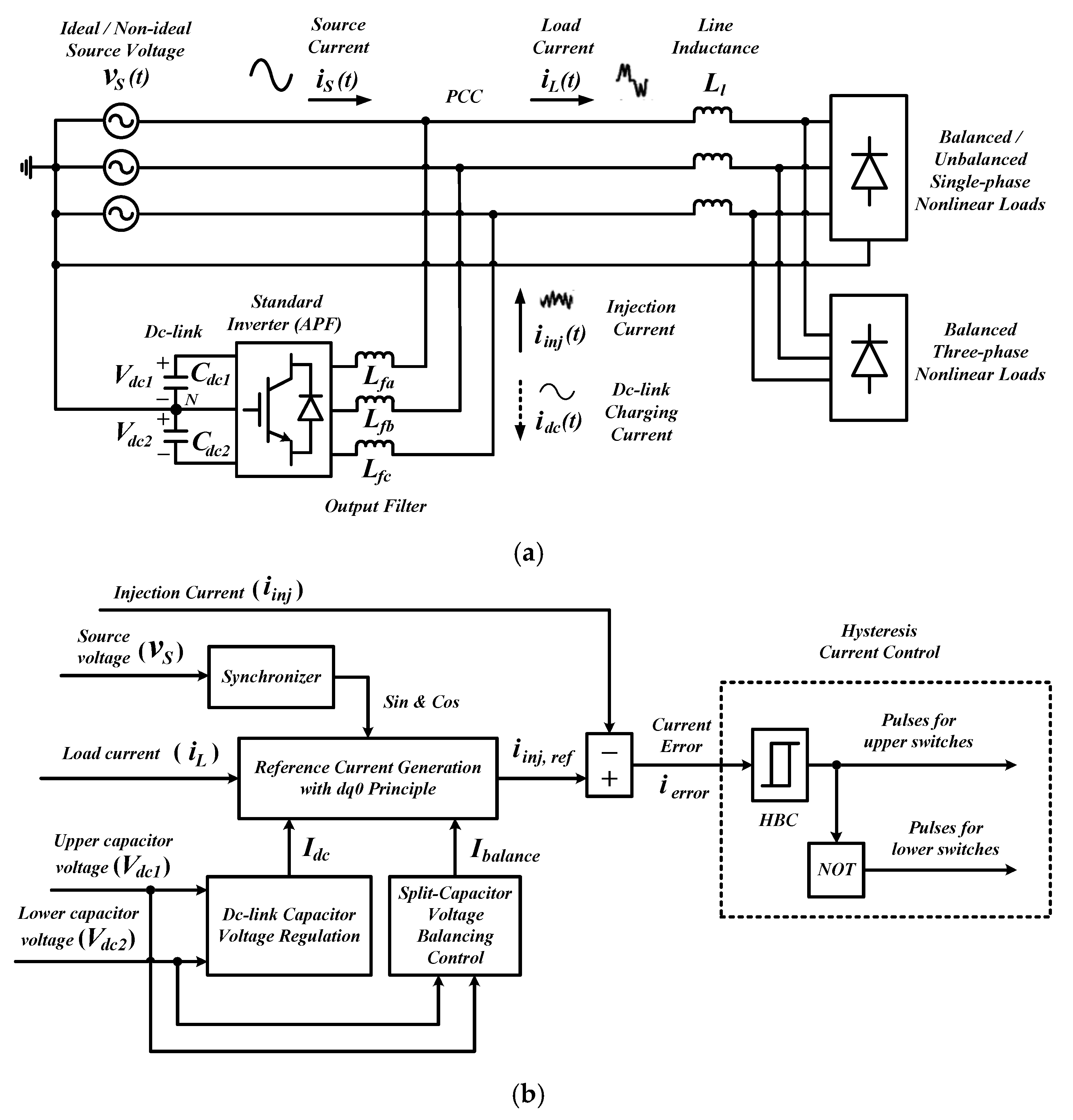
2. Three-Phase Three-Leg Four-Wire Shunt Active Power Filter: Arrangement of Power Circuits and Control Strategies

Figure 1 shows power circuit arrangement and control structure of a three-phase three-leg four-wire SAPF. A standard two-level inverter with two split dc-link capacitors (serving as the SAPF) is connected to the operating power system at point of common coupling (PCC) between the power supply and nonlinear loads. Note that there is an output filter interfacing between the SAPF and the connected power system. Its main purpose is to minimize switching ripples generated by SAPF so that mitigating opposition current (referred here as injection current i i n j ) can effectively be injected into any polluted power system to cancel out harmonic current. Furthermore, the middle-point of the two dc-link capacitors is connected to the return neutral wire N to minimize neutral current. In addition, while performing mitigation function, a certain amount of current (referred here as dc-link charging current i d c ) is also drawn by the SAPF to regulate voltage across its dc-link capacitors. In a three-phase four-wire power system, the connected nonlinear loads can be of single-phase balanced/unbalanced and three-phase balanced loads. When the SAPF is installed and functioning properly, harmonic current and excessive neutral current in the polluted power system will slowly be removed and eventually the source current will be balanced and regain its sinusoidal appearance with fundamental frequency, and neutral current will be maintained at zero.
To effectively manage operation of SAPF in a three-phase four-wire system, its control system needs to perform few control procedures which include extraction of synchronization phases ( sin   &   cos ) from source voltage v S , extraction of harmonic current from load current i L , estimation of I d c (magnitude of the dc-link charging current i d c ) and I b a l a n c e (balancing current) from split dc-link capacitor voltages ( V d c 1 and V d c 2 ), derivation of reference current i i n j ,   r e f by using all the signals obtained in the previous procedures, and generation of switching pulses based on the generated reference current i i n j ,   r e f . It is important to note that operation of a typical SAPF is fully based on characteristic of the generated reference current. In this work, other than mitigation of harmonic current, the SAPF is also needed to regulate its dc-link voltage and ensure voltage balance across its split dc-link capacitors. Hence, the generated reference current must contain details on system’s harmonics, compatible phases to ensure synchronized operation, amount of dc-link charging current to maintain constant dc-link voltage and balancing current to manage voltage balance of the two split dc-link capacitors.
This manuscript emphasizes on the control procedure of generating reference current where it is performed according to dq0 principle. Further details are presented in Section 3 and Section 4. Meanwhile, to regulate dc-link voltage and maintain voltage balance of the split dc-link capacitor, the conventional proportional-integral (PI) technique is adopted due to its straightforward feature [1,11]. Lastly, to generate switching pulses, a standard hysteresis band current control (HBC) technique is applied as it offers the benefits of structure simplicity and quick current controllability [1,2,6].

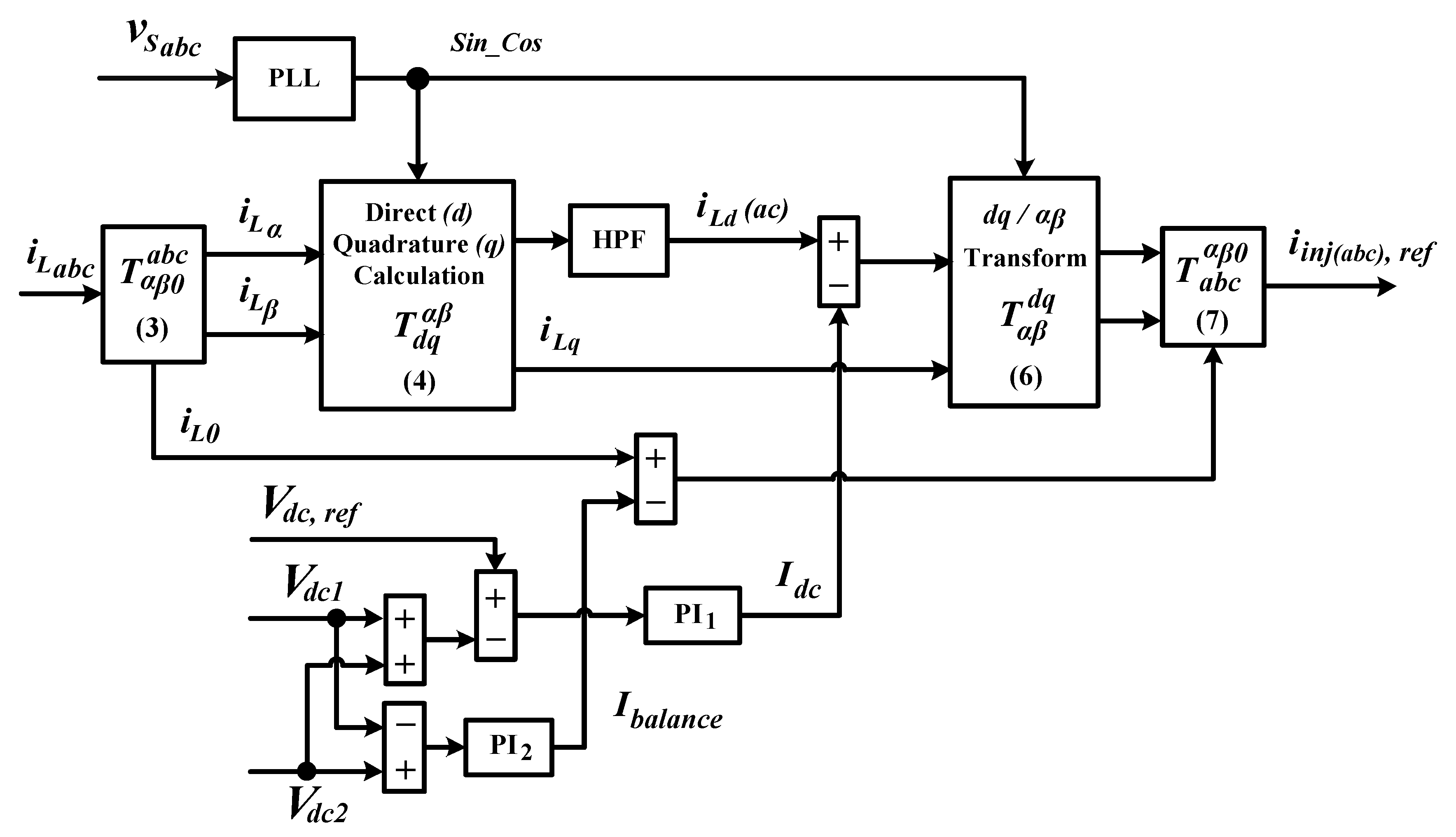
3. Working Principle of the Standard dq0 Technique

Figure 2 shows control structure of a standard dq0 technique which is commonly applied for the purpose of generating reference current. According to dq0 principle, extraction of harmonic current from load current is performed on dq0-frames where the load current i L a b c (in abc-domain) is first transformed into αβ0-domain by using Clarke-matrix expressed as Equation (1) and then into dq0-frames by using Park-matrix expressed as Equation (2).
T α β 0 a b c = 2 3   [ 1 1 2 1 2 0 3 2 3 2 1 2 1 2 1 2 ]
T d q α β = [ sin ( ω t ) cos ( ω t ) cos ( ω t ) sin ( ω t ) ]
Note that sin ( ω t ) and cos ( ω t ) denote synchronization reference phases which are particularly delivered by a PLL.
Let the three-phase load current expressed in matrix form be i L a b c = [ i L a   i L b   i L c ] T . Hence, by using Equation (1), the corresponding representation in αβ0-domain can be expressed as:
[ i L α i L β i L 0 ] T = T α β 0 a b c   [ i L a i L b i L c ] T .
Subsequently, load current i L α β in αβ-domain is further transformed into dq-frames according to Equation (4). Note that 0 -domain of αβ0-domain is not required in the transformation process, and it is directly applied as 0 -frame of dq0-frames. In other words, 0 -domain is equivalent to 0-frame.
[ i L d i L q ] T = T d q α β   [ i L α i L β ] T
In dq-frames, as a consequence of harmonic contamination, the load current signal contains both fundamental (stationary dc) and harmonic (oscillating ac) elements. Hence, the following relationship can be formed:
[ i L d i L q ] = [ i L d ( d c ) + i L d ( a c ) i L q ( d c ) + i L q ( a c ) ]
where i L d   ( d c ) and i L d   ( a c ) , respectively, denote the dc and ac elements of the load current in d-frame. The same representation applies to the elements of load current in q-frame. Note that the stationary dc element of d-frame represents the magnitude of fundamental load current whereas the oscillating ac element represents the magnitude of harmonic current. On the other hand, q-frame contains phase information of the load current. Not to forget, 0-frame of dq0-frames which is directly taken from that of αβ0-domain is needed to maintain dc-link voltage balance. In other words, the ac element of d-frame load current i L d ( a c ) , q-frame load current i L q and 0-frame load current i L 0 are three distinct unwanted parts of load currents that represent harmonic, reactive and unbalanced currents, respectively.
Hence, in order to remove those unwanted signals, to maintain constant dc-link voltage and to maintain voltage balance across the two split dc-link capacitors, the reference current i i n j ( a b c ) ,   r e f is derived by considering all those factors according to the following approach:
[ i L α ,   r e f i L β , r e f ] T = T α β d q   [ ( i L d ( a c ) I d c ) i L q ] T
[ i i n j a , r e f i i n j b , r e f i i n j c , r e f ] T = T a b c α β 0   [ i L α , r e f i L β , r e f ( i L 0 I b a l a n c e ) ] T
where inverse Park-matrix T α β d q and inverse Clarke-matrix T a b c α β 0 are given as follows:
T α β d q = [ sin ( ω t ) cos ( ω t ) cos ( ω t ) sin ( ω t ) ]
T a b c α β 0 = [ 1 0 1 1 2 3 2 1 1 2 3 2 1 ] .
Meanwhile, I d c symbolizes the amount of dc-link charging current i d c needed to maintain constant dc-link voltage at desired level (denoted as V d c ,   r e f ) and compensate losses associated with switching operation of SAPF, and I b a l a n c e symbolizes the amount of balancing current needed to maintain the voltage balance.
The oscillating ac element of d -frame load current i L d ( a c ) applied in Equation (6) can be obtained by filtering directly the d -frame load current with a high-pass filter (HPF) [1,6,12]. It is worth noting that in some d q 0 techniques, the oscillating ac element is also obtained indirectly by using low-pass filter (LPF) associated with a simple calculation, in which the LPF is first applied to obtain the stationary dc element i L d ( d c ) and is then subtracted from the actual d-frame load current i L d [13,14,15]. Next, I d c is estimated by minimizing the error e 1 ( t ) resulted between reference dc-link voltage V d c ,   r e f and the total instantaneous dc-link voltage ( V d c ( t ) = V d c 1 ( t ) + V d c 2 ( t ) ) with a PI controller. Mathematically, the approach can be expressed as:
I d c = k p 1 e 1 ( t ) + k i 1 0 t e 1 ( t ) d t
e 1 ( t ) = V d c ,   r e f ( V d c 1 ( t ) + V d c 2 ( t ) )
where k p 1 and k i 1 are the two constant values that respectively symbolize proportional and integral gains of PI1 (first PI) controller. In this work, the values are set to be 0.3 and 2, respectively. Similarly, a PI controller is applied to estimate I b a l a n c e by minimizing the error e 2 ( t ) resulted between the two split dc-link capacitors. Mathematically, the approach can be expressed as:
I b a l a n c e = k p 2 e 2 ( t ) + k i 2 0 t e 2 ( t ) d t
e 2 ( t ) = V d c 2 ( t ) V d c 1 ( t )
where k p 2 and k i 2 are the two constant values that respectively symbolize proportional and integral gains of PI2 (second PI) controller. The values are set to be 0.02 and 0.1, respectively.

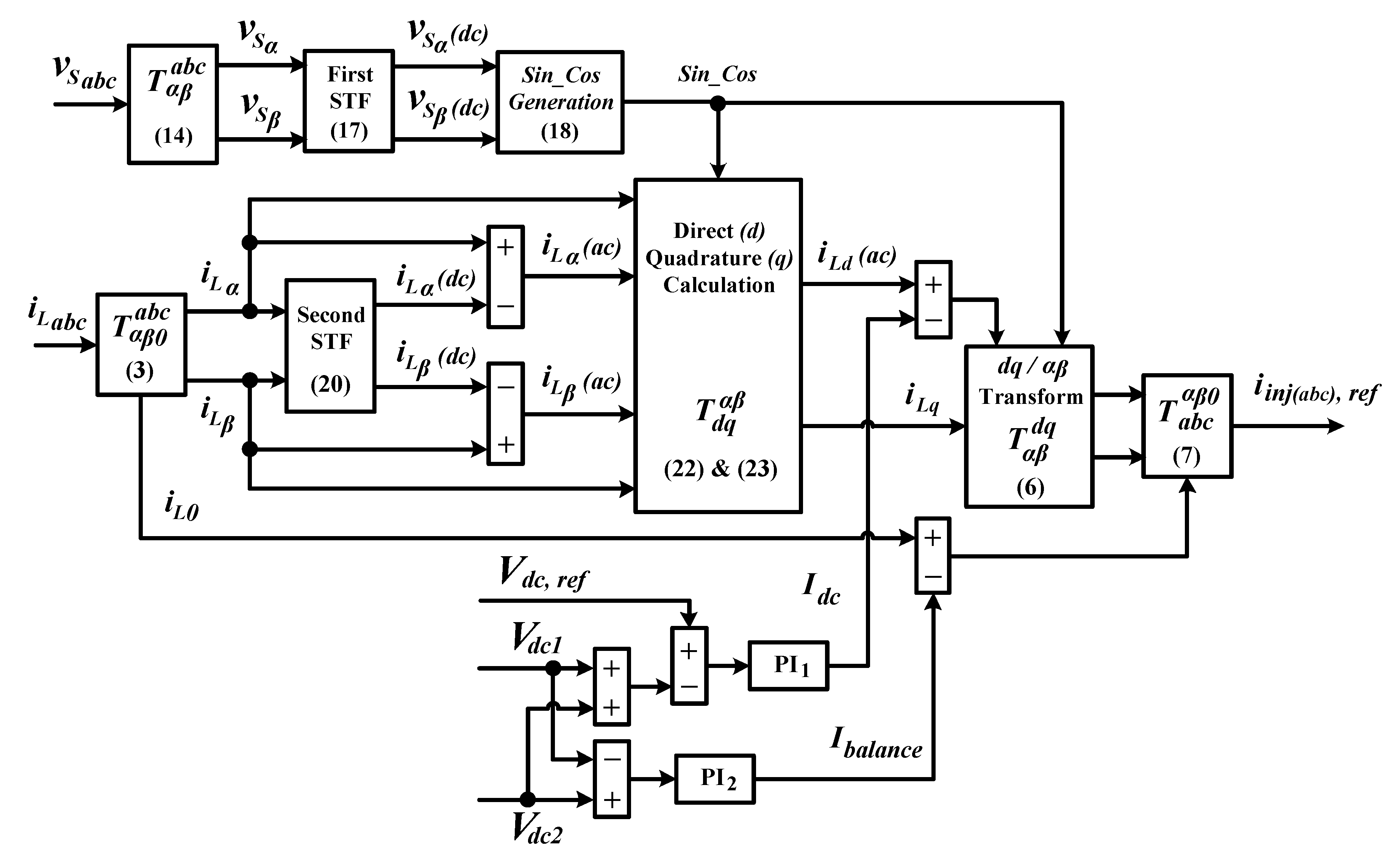
4. Working Principle the Proposed STF-dq0 Technique

Figure 3 presents a block diagram that illustrates control structure and particulars of the proposed STF-dq0 technique. Basically, the proposed STF-dq0 technique generates reference current in a similar manner to that of a standard dq0 technique where both techniques perform according to the consecutive transformation sequences of “abc-αβ0-dq0-αβ0-abc”. However, in the proposed technique, two modifications are made to further enhance capability of SAPF in performing its intended functions. First, the conventional PLL circuit is removed and replaced with a straightforward synchronization technique. Second, instead of applying HPF to perform direct extraction of harmonic element on dq0-frames, a self-tuning-filter (STF) is employed to extract the harmonic element indirectly on αβ0-domain (an earlier transformation stage before entering the dq0-frames).
In the proposed STF-dq0 technique, the process of extracting synchronization phases from the source voltage is rather straightforward and non-iterative. Let the three-phase source voltage expressed in matrix form be v S a b c = [ v S a   v S b   v S c ] T , and by using Clarke-transform matrix (considers only two phases αβ-domain), the source voltage signals (in abc-domain) can be transformed into αβ-domain according to:
[ v S α v S β ] T = T α β a b c   [ v S a v S b v S c ] T
where
T α β a b c = 2 3   [ 1 1 2 1 2 0 3 2 3 2 ] .
In αβ-domain, under influence of distortions, the voltage signals can respectively be decomposed into fundamental and harmonic elements. Hence, the following relationship can be formed:
[ v S α v S β ] = [ v S α ( d c ) + v S α ( a c ) v S β ( d c ) + v S β ( a c ) ]
where v S α ( d c ) and v S α ( a c ) denote the fundamental (dc) and harmonic (ac) elements of source voltage in α-domain, respectively. The same representation applies to element of source voltages in β-domain. To generate synchronization phases, the dc elements in both αβ-domain are required. A self-tuning filtering approach [16] is applied to extract the dc elements. The applied STF is capable of suppressing all the harmonic elements existed in the distorted voltage signals and thus improving quality of the extracted synchronization phases. As revealed in [16,17,18], the transfer function (after performing Laplace transformation) of a typical STF can be expressed as follow:
[ v S α ( d c ) ( s ) v S β ( d c ) ( s ) ] = K 1 s [ v S α ( s ) v S α ( d c ) ( s ) v S β ( s ) v S β ( d c ) ( s ) ] + 2 π f c 1 s [ v S β ( d c ) ( s ) v S α ( d c ) ( s ) ]
where K 1 is a constant gain parameter and f c 1 is the cutoff frequency of STF1 (first STF). In this work, the values are set to be 20 and 50 Hz, respectively. With availability of v S α ( d c ) and v S β ( d c ) , the synchronization phases, sin ( ω t ) and cos ( ω t ) can be obtained according to following approach:
[ sin ( ω t ) cos ( ω t ) ] = 1 v S α ( d c ) 2 + v S β ( d c ) 2 [ v S α ( d c ) v S β ( d c ) ] .
By using Equation (18), the service from conventional PLL can be neglected and the synchronization phases can now effectively be generated regardless of any distortions in the source voltage.
On the other hand, for harmonic extraction, a STF is also employed to perform indirect extraction of harmonic elements from the load current on αβ-domain. By using Equation (3), the three-phase load current in a b c -domain is first transformed into αβ-domain. Focusing only on αβ-domain (0-domain does not involve in harmonic extraction), due to harmonic contamination, the load current signals i L α β can respectively be decomposed into fundamental and harmonic elements. Hence, the following relationship can be formed:
[ i L α i L β ] = [ i L α ( d c ) + i L α ( a c ) i L β ( d c ) + i L β ( a c ) ]
where i L α ( d c ) and i L α ( a c ) denote the fundamental (dc) and harmonic (ac) elements of load current in α-domain, respectively. The same representation applies to elements of load current in β-domain.
The transfer function (after performing Laplace transformation) of STF applied to extract the dc elements ( i L α ( d c ) and i L β ( d c ) ) of load current in αβ-domain is given as follows:
[ i L α ( d c ) ( s ) i L β ( d c ) ( s ) ] = K 2 s [ i L α ( s ) i L α ( d c ) ( s ) i L β ( s ) i L β ( d c ) ( s ) ] + 2 π f c 2 s [ i L β ( d c ) ( s ) i L α ( d c ) ( s ) ] .
where K 2 is a constant gain parameter and f c 2 is the cutoff frequency of STF2 (second STF). In this work, the values are set to be 20 and 50 Hz, respectively. With availability of dc elements ( i L α ( d c ) and i L β ( d c ) ), the ac elements ( i L α ( a c ) and i L β ( a c ) ) can be obtained by using simple calculation expressed as:
[ i L α ( a c ) i L β ( a c ) ] = [ i L α i L α ( d c ) i L β i L β ( d c ) ] .
From Equation (21), it can be seen that according to this STF approach, the ac elements are obtained by subtracting the dc elements (extracted in advance using the STF) from the actual load current signal in αβ-domain i L α β . Therefore, in this manner, the harmonic or ac elements are said to be extracted indirectly.
Next, the ac elements obtained from Equation (21) and synchronization phases obtained from Equation (18) are applied to perform transformation of αβ-domain into d-frame (contains only ac elements) according to the following approach:
i L d ( a c ) = i L α ( a c ) sin ( ω t ) + i L β ( a c ) cos ( ω t )
and meanwhile, the original load current signal in αβ-domain i L α β and the similar synchronization phases are applied to perform transformation of αβ-domain into q-frame according to the following approach:
i L q = i L α cos ( ω t ) + i L β sin ( ω t ) .
Note that 0-domain of αβ0-domain does not need to be transformed, and it is directly applied as 0-frame of dq0-frames. Finally, together with I d c (obtained from Equation (10)) and I b a l a n c e (obtain from Equation (12)), Equations (6) and (7) are applied to generate the reference current i i n j ( a b c ) ,   r e f .

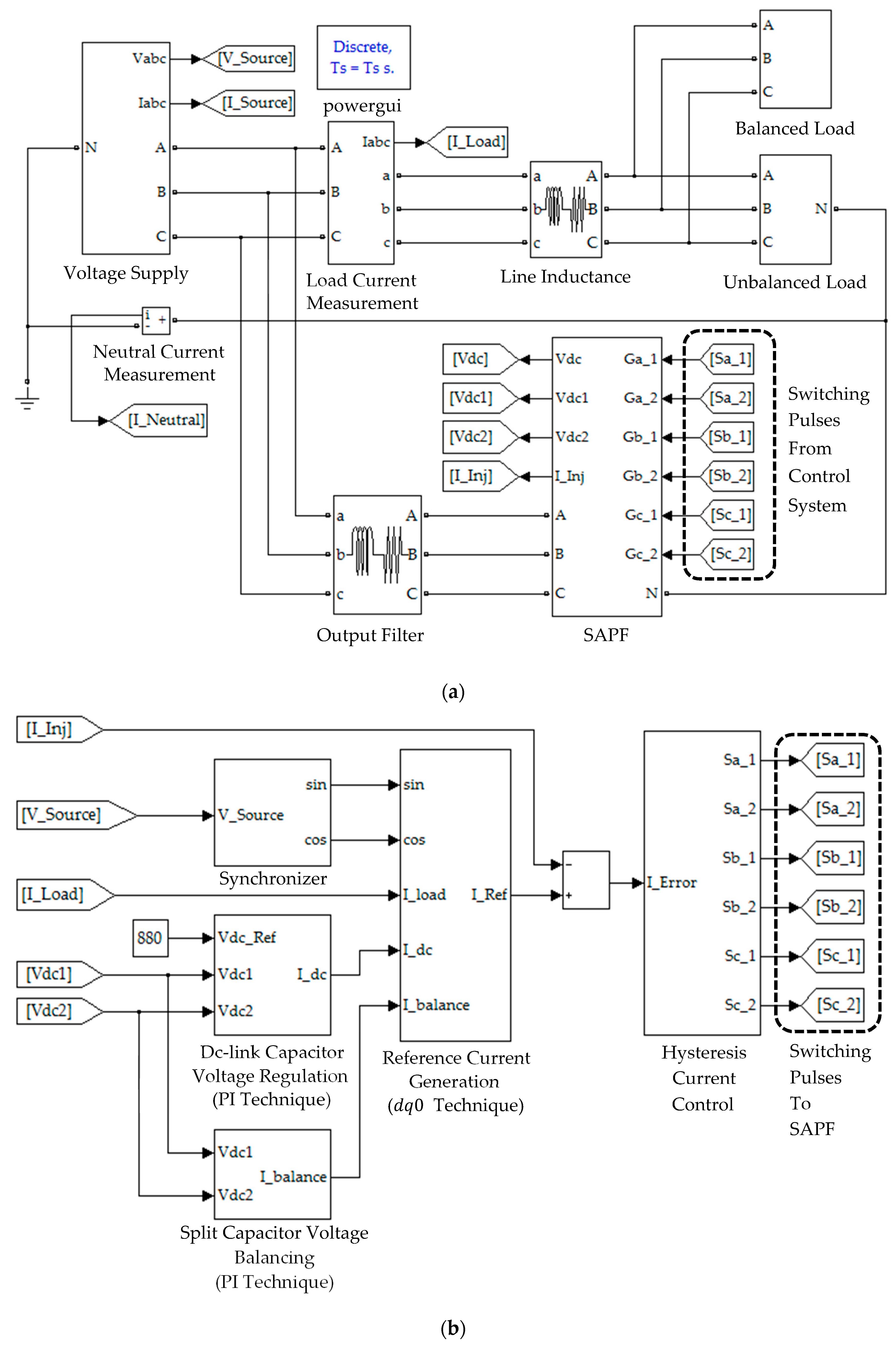
5. Results and Discussion

Simulation work which includes connection of SAPF circuits, design of its control system, and performance assessment of the proposed STF-dq0 technique is performed in MATLAB-Simulink platform (R2012a). Figure 4 shows the simulation model developed for this work. It is constructed using simple Simulink-blocks, and is executed in discrete environment. A standard two-level inverter with split dc-link capacitors of 3300 μF (each) is employed as the SAPF. Its output is connected to a simple 5 mH L -typed filter to minimize switching ripples. The line inductance is set to be 1 mH. For this work, the reference dc-link voltage is set to be 880 V (440 V for each split capacitor). The procedures applied for designing and determining parameter specifications of the SAPF are reported in [19,20,21]. Meanwhile, for the sources of harmonics, two types of nonlinear loads are considered. The first nonlinear load comprises of three single-phase nonlinear loads distributed unequally (in unbalanced manner) across the three phases of the connected power system (referred here as Load 1). The second nonlinear load comprises of three unbalanced single-phase nonlinear loads connected in parallel with a balanced three-phase nonlinear load (referred here as Load 2). Particulars of Loads 1 and 2 are summarized in Table 1.
Analysis is performed in a comparative manner, i.e., by benchmarking performance demonstrated by SAPF while applying the proposed STF-dq0 technique, with the one using the standard dq0 technique. Steady-state simulation studies are conducted, considering four scenarios of source voltages, i.e., in scenario A, a sinusoidal-balanced source voltage, in scenario B, non-sinusoidal-balanced source voltage, in scenario C, sinusoidal-unbalanced source voltage, and in scenario D, non-sinusoidal-unbalanced source voltage. For these four scenarios, particulars of the source voltages applied are given as follows:
Scenario A: Sinusoidal-balanced source voltage:
(THDa = THDb = THDc = 0.00%)
v S a = 326 sin ( ω t )
v S b = 326 sin ( ω t + 240 ° )
v S c = 326 sin ( ω t + 120 ° ) .
Scenario B: Non-sinusoidal-balanced source voltage:
(THDa = THDb = THDc = 20.80%)
v S a = 326 sin ( ω t ) + 50 sin ( 3 ω t ) + 40 sin ( 5 ω t ) + 20 sin ( 7 ω t ) + 10 sin ( 9 ω t )
v S b = 326 sin ( ω t + 240 ° ) + 50 sin ( 3 ( ω t + 240 ° ) ) + 40 sin ( 5 ( ω t + 240 ° ) ) + 20 sin ( 7 ( ω t + 240 ° ) ) + 10 sin ( 9 ( ω t + 240 ° ) )
v S c = 326 sin ( ω t + 120 ° ) + 50 sin ( 3 ( ω t + 120 ° ) ) + 40 sin ( 5 ( ω t + 120 ° ) ) + 20 sin ( 7 ( ω t + 120 ° ) ) + 10 sin ( 9 ( ω t + 120 ° ) ) .
Scenario C: Sinusoidal-unbalanced source voltage:
(THDa = THDb = THDc = 0.00%)
v S a = 326 sin ( ω t )
v S b = 246 sin ( ω t + 240 ° )
v S c = 286 sin ( ω t + 120 ° ) .
Scenario D: Non-sinusoidal-unbalanced source voltage
(THDa = 16.80%, THDb = 15.74%and THDc = 6.99%)
v S a = 326 sin ( ω t ) + 40 sin ( 3 ω t ) + 30 sin ( 5 ω t ) + 20 sin ( 7 ω t ) + 10 sin ( 9 ω t )
v S b = 246 sin ( ω t + 240 ° ) + 30 sin ( 3 ( ω t + 240 ° ) ) + 20 sin ( 5 ( ω t + 240 ° ) ) + 10 sin ( 7 ( ω t + 240 ° ) ) + 10 sin ( 9 ( ω t + 240 ° ) )
v S c = 286 sin ( ω t + 120 ° ) + 10 sin ( 3 ( ω t + 120 ° ) ) + 10 sin ( 5 ( ω t + 120 ° ) ) + 10 sin ( 7 ( ω t + 120 ° ) ) + 10 sin ( 9 ( ω t + 120 ° ) ) .

5.1. Sinusoidal-Balanced Source Voltage (Scenario A)

In Scenario A, an ideal situation of sinusoidal-balanced source voltage is considered. All the simulation waveforms obtained under this scenario are shown in Figure 5, Figure 6, Figure 7, Figure 8 and Figure 9. Meanwhile, Table 2 summarizes the findings in comparative manner. Referring to Figure 5, it can clearly be observed that both the proposed STF-dq0 and standard dq0 techniques are able to accurately detect synchronization phase value ω t (appear in the form of sawtooth wave-shape) from a sinusoidal-balanced source voltage. Next, from Figure 6, both techniques are revealed to have effectively directed their respective SAPF in mitigating harmonic currents generated by Loads 1, where the source currents are found to have regained sinusoidal shape with THD values (as tabulated in Table 2) well-maintained below the 5% harmonic limit set by IEEE standard 519 [22]. Note that no significant differences can be observed between the THD values resulted by the proposed STF-dq0 and standard dq0 techniques. In addition, it also can be seen that high neutral currents caused by connection of single-phase loads has effectively been reduced by both SAPFs, proving the ability of both techniques in removing excessive neutral currents.
Furthermore, as indicated in Table 2, large phase differences that resulted between the source current and voltage have been minimized by both SAPFs. In other words, it proves that both techniques are able to effectively synchronize operation of SAPF with the operating power system. This is basically due to the accurate synchronization phase value ω t detected by both techniques (as indicated in Figure 5). As a result, the source current seems to work in phase with the source voltage and thus it leads to almost unity power factor of 0.999. Similar findings can be observed for Load 2, as indicated in Figure 8 and Table 2. Therefore, as an overall, both techniques show almost similar performances when operating under sinusoidal-balanced source voltage scenario.
Other than effective harmonic mitigation, ability to regulate dc-link voltage is also an important feature of SAPF, thus must thoroughly be assessed. Figure 7 and Figure 9 provide the related results. From the findings, while applying the proposed STF-dq0 technique, the SAPF is found to have effectively regulated and maintained its dc-link voltage at the desired level of 880 V, for both Loads 1 and 2. Similarly, it is also clear from the findings that voltages across the two split dc-link capacitors ( V d c 1 and V d c 2 ) are evenly regulated at half the value of overall dc-link voltage V d c , i.e., 440 V. This implies that the two PI techniques applied respectively for regulating the dc-link voltage and ensuring voltage balance of the two split dc-link capacitors have performed effectively and are compatible with the proposed STF-dq0 technique.

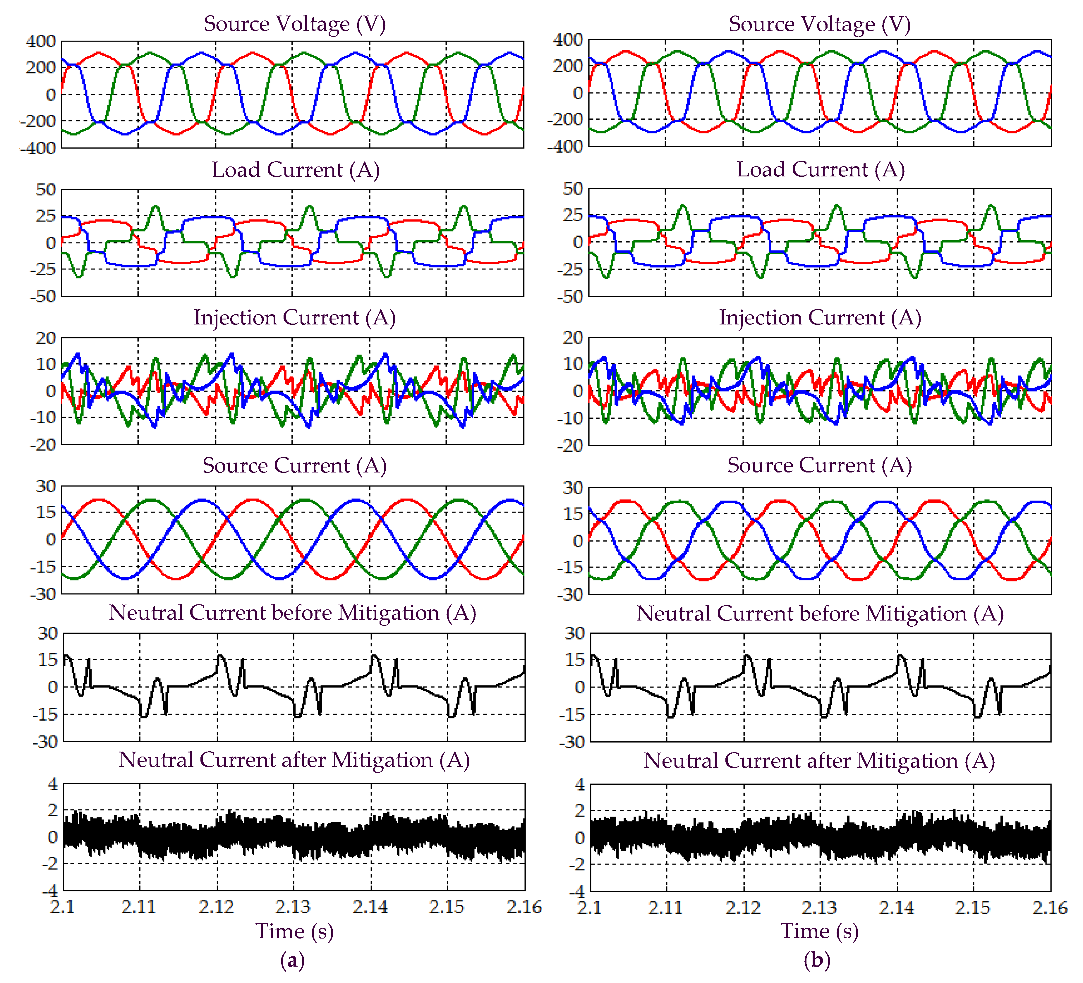
5.2. Non-Sinusoidal-Balanced Source Voltage (Scenario B)

In Scenario B, a non-sinusoidal-balanced (harmonic distorted) source voltage is considered. All the simulation waveforms obtained under this scenario are shown in Figure 10, Figure 11, Figure 12, Figure 13 and Figure 14. Meanwhile, Table 3 summarizes the findings in comparative manner. Referring to Figure 10, it can clearly be observed that the proposed STF-dq0 technique effectively detects synchronization phase value ω t (appear in the form of sawtooth wave-shape) from a non-sinusoidal-balanced source voltage, where the detected phase value is found to accurately match the desired phase value. In contrast, for the standard d q 0 technique, discrepancies existed between the detected and desired phase value, where the resulted sawtooth waveform of the detected phase value is observed to be oscillating along the desired phase value. This implies that the standard d q 0 technique cannot work as desired when the source voltage suffers from distortion.
Next, referring to Figure 11, it can be seen that while using the proposed STF-dq0 technique, SAPF is observed to have successfully mitigated harmonic currents generated by Load 1, where the source currents have regained sinusoidal shape with THD values (as tabulated in Table 3) complying with the 5% harmonic limit. In contrast, SAPF that applies the standard dq0 technique is only capable of reducing distortion level suffered by the source currents but it fails to provide mitigation performance that complies with IEEE standard 519. In this case, the mitigated source currents fail to recover the desired sinusoidal shape and the recorded THD values are far beyond 5%. Nevertheless, both techniques are able to remove excessive neutral currents caused by connection of single-phase loads.
Furthermore, as indicated in Table 3, both techniques are able to direct their respective SAPF in minimizing the large phase differences that resulted between the source current and voltage. With minimum phase differences, an almost unity power factor of 0.999 can be achieved when the proposed STF-dq0 technique is applied. In contrast, due to high-level of distortion retained in the mitigated source current, the standard dq0 technique can only provide a power factor up to 0.997 even though the phase differences have been minimized. Similar findings can be observed for Load 2, where the proposed STF-dq0 technique is revealed to outperform the standard dq0 technique when operating under non-sinusoidal-balanced source voltage scenario (as indicated in Figure 13 and Table 3).
Moreover, the assessment on behavior of dc-link voltage is also conducted to confirm correct operation of SAPF under Scenario B, while applying the proposed STF-dq0 technique. Figure 12 and Figure 14 provide the related results recorded for Loads 1 and 2, respectively. As expected from the findings, all dc-link voltages of the SAPF are effectively regulated and maintained at the desired level, i.e., at 880 V for the overall dc-link voltage V d c and at 440 V (half of overall dc-link voltage) for the voltages across two split dc-link capacitors ( V d c 1 and V d c 2 ). Hence, once again, it is certain that the proposed STF-dq0 technique can work effectively together with the two PI techniques applied respectively for regulating the dc-link voltage and ensuring voltage balance of the two split dc-link capacitors, and eventually directed the SAPF to work as desired under non-sinusoidal-balanced source voltage scenario.

5.3. Sinusoidal-Unbalanced Source Voltage (Scenario C)

In Scenario C, a sinusoidal-unbalanced (magnitude unbalanced) source voltage is considered. All the simulation waveforms obtained under this scenario are shown in Figure 15, Figure 16, Figure 17, Figure 18 and Figure 19. Meanwhile, Table 4 summarizes the findings in comparative manner. Based on Figure 15, the synchronization phase value ω t (appear in the form of sawtooth wave-shape) detected by the proposed STF-dq0 technique is found to work in accordance with the desired phase value. In contrast, for the standard dq0 technique, minor discrepancies can be observed between the detected and desired phase value. Hence, it implies that the standard dq0 technique cannot work exactly as desired when the magnitude of a three-phase source voltage is unbalanced across the three phases.
Subsequently, from Figure 16, it is obvious that by using the proposed STF-dq0 technique, SAPF have successfully mitigated harmonic currents generated by Load 1, where the source currents have regained sinusoidal shape with THD values (as tabulated in Table 4) complying with the 5% harmonic limit. In contrast, SAPF that applies the standard dq0 technique fails to perform in accordance to IEEE standard 519, where the recorded THD values are beyond 5% and the mitigated source currents fail to regain a complete sinusoidal shape. Nevertheless, both techniques are able to remove excessive neutral currents caused by connection of single-phase loads. Furthermore, as indicated in Table 4, both techniques are found to be able to direct their respective SAPF in minimizing the large phase differences that resulted between the source current and voltage. With minimum phase differences, an almost unity power factor of 0.999 can be achieved when the proposed STF-dq0 technique is applied. However, due to higher distortion level of the mitigated source current, the standard dq0 technique can only provide a power factor up to 0.998 even though the phase differences have been minimized.
On the other hand, for the case of Load 2 as illustrated in Figure 18, both the proposed STF-dq0 and the standard dq0 techniques are found to perform effectively as the THD values have been maintained below the 5% harmonic limit, excessive neutral current have been removed, the large phase differences have been minimized, and almost unity power factor of 0.999 is achieved. Nevertheless, the proposed STF-dq0 technique is revealed to outperform the standard dq0 technique by providing THD values of 1.88–2.13% lower (as indicated in Table 4). Hence, as an overall, judging from the performance of each technique in dealing with Loads 1 and 2, the proposed STF-dq0 technique can be claimed to be more reliable than the standard dq0 technique when they are required to work under sinusoidal-unbalanced source voltage scenario.
Moreover, assessment on behavior of dc-link voltage is also conducted to further justify that the SAPF is working correctly under Scenario C, while applying the proposed STF-dq0 technique. Figure 17 and Figure 19 provide the related results obtained for Loads 1 and 2, respectively. As expected, all dc-link voltages of the SAPF are effectively regulated and maintained at the desired level, i.e., overall dc-link voltage V d c at 880 V and voltages across the two split dc-link capacitors ( V d c 1 and V d c 2 ) at 440 V (half of overall dc-link voltage). Hence, once again, it is certain that the SAPF can work appropriately under sinusoidal-unbalanced source voltage scenario while applying the proposed STF-dq0 technique.

5.4. Non-Sinusoidal-Unbalanced Source Voltage (Scenario D)

In Scenario D, a non-sinusoidal-unbalanced (harmonic distorted and magnitude unbalanced) source voltage is considered. All the simulation waveforms obtained under this scenario are shown in Figure 20, Figure 21, Figure 22, Figure 23 and Figure 24. Meanwhile, Table 5 summarizes the findings in comparative manner. As shown in Figure 20, the synchronization phase value ω t (appear in the form of sawtooth wave-shape) detected by the proposed STF-dq0 technique is in line with the desired phase value. In contrast, for the standard dq0 technique, the detected phase value seems to be oscillating along the desired phase value. Hence, once again the findings show that the proposed STF-dq0 technique can accurately track the desired phase value when the source voltage is distorted and unbalanced, while the standard dq0 technique has failed to do so.
Next, from Figure 21 and Figure 23, it is clear that by using the proposed STF-dq0 technique, the SAPF have successfully mitigated harmonic currents generated by Loads 1 and 2, where the mitigated source currents for both cases have regained sinusoidal shape with THD values (as tabulated in Table 5) complying with the 5% harmonic limit. However, SAPF that applies the standard dq0 technique fails to comply with IEEE standard 519 in both cases, where the recorded THD values are beyond 5% and the mitigated source currents fail to recover the desired sinusoidal shape. Nevertheless, both techniques are able to remove excessive neutral currents caused by connection of single-phase loads.
In addition, as indicated in Table 5, both techniques have effectively minimized the large phase differences between the source current and voltage caused by connection of Loads 1 and 2. With minimum phase differences, almost unity power factor of 0.999 can be achieved when the proposed STF-dq0 technique is applied. However, due to higher distortion level of the mitigated source current, the standard dq0 technique can only provide a power factor up to 0.998 even though the phase differences have been minimized.
Furthermore, assessment on behaviour of dc-link voltage is also conducted to justify that the SAPF is working correctly under Scenario D, while applying the proposed STF-dq0 technique. Figure 22 and Figure 24 provide the related results obtained for Loads 1 and 2, respectively. From the results obtained, all dc-link voltages of the SAPF are revealed to have effectively been regulated and maintained at the desired level, i.e., overall dc-link voltage V d c at 880 V and voltages across the two split dc-link capacitors ( V d c 1 and V d c 2 ) at 440 V (half of overall dc-link voltage). Hence, once again, it is certain that the SAPF can work appropriately under non-sinusoidal-unbalanced source voltage scenario while applying the proposed STF-dq0 technique.
Overall, based on all the findings obtained in Scenarios A to D, design concept and functionality of the proposed STF-dq0 technique can be confirmed to be correct. By applying the proposed STF-dq0 technique, the SAPF is revealed to perform effectively in dealing with both unbalanced nonlinear loads and all the scenarios of source voltages which have been considered in this work. The highly distorted source currents have regained the desired sinusoidal shape with low THD values ranging from 0.92% to 2.97%, complying with IEEE standard 519. Next, excessive neutral currents have been reduced to a level that the mitigated source currents are balanced. In addition, large phase differences have been reduced to the range of 0.00–0.80°, thereby achieving power factor of 0.999 which is almost unity. Furthermore, all dc-link capacitor voltages have been regulated as desired and are balanced, thus ensuring that the SAPF is able to mitigate harmonics appropriately. More importantly, the proposed STF-dq0 technique outperforms and is more reliable than the standard dq0 technique when dealing with distorted and unbalanced source voltages.

6. Conclusions

In this paper, a control technique that generates reference current to manage operation of a three-phase four-wire SAPF has successfully been demonstrated. The proposed technique is named as the STF-dq0 technique, as it is developed by integrating together the strengths of STF and working concept of the dq0 principle, without relying on any PLL element. Comprehensive tests and analyses involving two types of unbalanced nonlinear rectifier loads and four distinct scenarios of source voltages are conducted to evaluate performance of the proposed STF-dq0 technique in comparison to the standard dq0 technique. Based on the exhaustive simulation results presented, the proposed technique is revealed to perform effectively regardless of specifications of nonlinear loads and scenarios of source voltages. More importantly, the proposed STF-dq0 technique is demonstrated to be superior and more reliable than the standard dq0 technique especially when dealing with distorted and unbalanced source voltages. Low THD values complying with IEEE standard 519, synchronized operation of SAPF, minimized neutral current and power factor reaching almost unity, are the benefits granted by the proposed technique when it is applied in three-phase four-wire system.

Author Contributions

Y.H. designed and developed the simulation model, conducted all the necessary tests and analyses for the research work, and prepared the initial draft of the manuscript. M.A.M.R contributed in the simulation work, verifying the work and improving the manuscript. Both worked together in finalizing the manuscript.

Funding

This research received no external funding.

Conflicts of Interest

The authors declare no conflict of interest.

References

  1. Kale, M.; Ozdemir, E. A new hysteresis band current control technique for a shunt active filter. Turk. J. Electr. Eng. Comput. Sci. 2015, 23, 654–665. [Google Scholar] [CrossRef]
  2. Ucar, M.; Ozdemir, E. Control of a 3-phase 4-leg active power filter under non-ideal mains voltage condition. Electr. Power Syst. Res. 2008, 78, 58–73. [Google Scholar] [CrossRef]
  3. Escobar, G.; Valdez, A.A.; Torres-Olguin, R.E.; Martinez-Montejano, M.F. A model-based controller for a three-phase four-wire shunt active filter with compensation of the neutral line current. IEEE Trans. Power Electron. 2007, 22, 2261–2270. [Google Scholar] [CrossRef]
  4. Bhattacharya, A.; Chakraborty, C.; Bhattacharya, S. Shunt compensation—Reviewing traditional methods of reference current generation. IEEE Ind. Electron. Mag. 2009, 3, 38–49. [Google Scholar] [CrossRef]
  5. Green, T.C.; Marks, J.H. Control techniques for active power filters. IEE Proc. Electr. Power Appl. 2005, 152, 369–381. [Google Scholar] [CrossRef]
  6. Kale, M.; Ozdemir, E. An adaptive hysteresis band current controller for shunt active power filter. Electr. Power Syst. Res. 2005, 73, 113–119. [Google Scholar] [CrossRef]
  7. Mikkili, S.; Panda, A.K. Instantaneous active and reactive power and current strategies for current harmonics cancellation in 3-ph 4-wire SHAF with both PI and fuzzy controllers. Energy Power Eng. 2011, 3, 285–298. [Google Scholar] [CrossRef]
  8. Eskandarian, N.; Beromi, Y.A.; Farhangi, S. Improvement of dynamic behavior of shunt active power filter using fuzzy instantaneous power theory. J. Power Electron. 2014, 14, 1303–1313. [Google Scholar] [CrossRef]
  9. Rodriguez, P.; Pou, J.; Bergas, J.; Candela, J.I.; Burgos, R.P.; Boroyevich, D. Decoupled double synchronous reference frame PLL for power converters control. IEEE Trans. Power Electron. 2007, 22, 584–592. [Google Scholar] [CrossRef]
  10. Campanhol, L.B.G.; Silva, S.A.O.; Goedtel, A. Application of shunt active power filter for harmonic reduction and reactive power compensation in three-phase four-wire systems. IET Power Electron. 2014, 7, 2825–2836. [Google Scholar] [CrossRef]
  11. Ucar, M.; Ozdemir, S.; Ozdemir, E. A unified series-parallel active filter system for nonperiodic disturbances. Turk. J. Electr. Eng. Comput. Sci. 2011, 19, 575–596. [Google Scholar]
  12. Senini, S.; Wolfs, P.J. Analysis and design of a multiple-loop control system for a hybrid active filter. IEEE Trans. Ind. Electron. 2002, 49, 1283–1292. [Google Scholar] [CrossRef]
  13. Hoon, Y.; Radzi, M.A.M.; Hassan, M.K.; Mailah, N.F. Three-phase three-level shunt active power filter with simplified synchronous reference frame. In Proceedings of the IEEE Industrial Electronics and Applications Conference, Kota Kinabalu, Sabah, Malaysia, 20–22 November 2016; pp. 1–6. [Google Scholar]
  14. Monfared, M.; Golestan, S.; Guerrero, J.M. A new synchronous reference frame-based method for single-phase shunt active power filters. J. Power Electron. 2013, 13, 692–700. [Google Scholar] [CrossRef]
  15. Jain, N.; Gupta, A. Comparison between two compensation current control methods of shunt active power filter. Int. J. Eng. Res. Gen. Sci. 2014, 2, 603–615. [Google Scholar]
  16. Abdulsalam, M.; Poure, P.; Karimi, S.; Saadate, S. New digital reference current generation for shunt active power filter under distorted voltage conditions. Electr. Power Syst. Res. 2009, 79, 759–765. [Google Scholar] [CrossRef]
  17. Biricik, S.; Redif, S.; Özerdem, Ö.C.; Khadem, S.K.; Basu, M. Real-time control of shunt active power filter under distorted grid voltage and unbalanced load condition using self-tuning filter. IET Power Electron. 2014, 7, 1895–1905. [Google Scholar] [CrossRef] [Green Version]
  18. Djazia, K.; Krim, F.; Chaoui, A.; Sarra, M. Active power filtering using the zdpc method under unbalanced and distorted grid voltage conditions. Energies 2015, 8, 1584–1605. [Google Scholar] [CrossRef]
  19. Jain, S.K.; Agrawal, P.; Gupta, H.O. Design simulation and experimental investigations, on a shunt active power filter for harmonics, and reactive power compensation. Electr. Power Compon. Syst. 2003, 31, 671–692. [Google Scholar] [CrossRef]
  20. Krim, F. Parameters estimation of shunt active filter for power quality improvement. In Proceedings of the 5th International Power Engineering and Optimization Conference (PEOCO), Shah Alam, Selangor, Malaysia, 6–7 June 2011; pp. 306–311. [Google Scholar]
  21. Jain, S.K.; Agrawal, P.; Gupta, H.O. Fuzzy logic controlled shunt active power filter for power quality improvement. IEE Proc. Electr. Power Appl. 2002, 149, 317–328. [Google Scholar] [CrossRef]
  22. Institute of Electrical and Electronics Engineers (IEEE). IEEE recommended practice and requirement for harmonic control in electric power systems. In IEEE Std 519-2014 (Revision of IEEE Std 519-1992); IEEE: Piscataway, NJ, USA, 2014; pp. 1–29. [Google Scholar]
Figure 1. Three-phase three-leg four-wire shunt active power filter (SAPF) with two split dc-link capacitors: (a) power circuit arrangement, and (b) overall control structure.
Energies 11 02143 g001
Figure 2. Block diagram showing control structure of standard dq0 technique [1].
Energies 11 02143 g002
Figure 3. Block diagram showing control structure of the proposed self-tuning-filter (STF)-dq0 technique.
Energies 11 02143 g003
Figure 4. Simulation model of three-phase three-leg four-wire SAPF developed in MATLAB-Simulink platform: (a) power circuit arrangement, and (b) control system.
Energies 11 02143 g004
Figure 5. Simulation result showing the detected synchronization reference phase value ω t under Scenario A.
Energies 11 02143 g005
Figure 6. Simulation results obtained under Scenario A for Load 1, which include three-phase source voltage v S a b c , load current i L a b c , injection current i i n j a b c , source current i S a b c , and neutral current before and after mitigation, demonstrated by SAPF while applying the (a) proposed STF-dq0 and (b) standard dq0 techniques.
Energies 11 02143 g006
Figure 7. Simulation result obtained under Scenario A for Load 1, showing the total dc-link voltage V d c , and voltages across split dc-link capacitors V d c 1 and V d c 2 , demonstrated by SAPF while applying the proposed STF-dq0 technique.
Energies 11 02143 g007
Figure 8. Simulation results obtained under Scenario A for Load 2, which include three-phase source voltage v S a b c , load current i L a b c , injection current i i n j a b c , source current i S a b c , and neutral current before and after mitigation, demonstrated by SAPF while applying the (a) proposed STF-dq0 and (b) standard dq0 techniques.
Energies 11 02143 g008
Figure 9. Simulation result obtained under Scenario A for Load 2, showing the total dc-link voltage V d c , and voltages across split dc-link capacitors V d c 1 and V d c 2 , demonstrated by SAPF while applying the proposed STF-dq0 technique.
Energies 11 02143 g009
Figure 10. Simulation result showing the detected synchronization reference phase value ω t under Scenario B.
Energies 11 02143 g010
Figure 11. Simulation results obtained under Scenario B for Load 1, which include three-phase source voltage v S a b c , load current i L a b c , injection current i i n j a b c , source current i S a b c , and neutral current before and after mitigation, demonstrated by SAPF while applying the (a) proposed STF-dq0 and (b) standard dq0 techniques.
Energies 11 02143 g011
Figure 12. Simulation result obtained under Scenario B for Load 1, showing the total dc-link voltage V d c , and voltages across split dc-link capacitors V d c 1 and V d c 2 , demonstrated by SAPF while applying the proposed STF-dq0 technique.
Energies 11 02143 g012
Figure 13. Simulation results obtained under Scenario B for Load 2, which include three-phase source voltage v S a b c , load current i L a b c , injection current i i n j a b c , source current i S a b c , and neutral current before and after mitigation, demonstrated by SAPF while applying the (a) proposed STF-dq0 and (b) standard dq0 techniques.
Energies 11 02143 g013
Figure 14. Simulation result obtained under Scenario B for Load 2, showing the total dc-link voltage V d c , and voltages across split dc-link capacitors V d c 1 and V d c 2 , demonstrated by SAPF while applying the proposed STF-dq0 technique.
Energies 11 02143 g014
Figure 15. Simulation result showing the detected synchronization reference phase value ω t under Scenario C.
Energies 11 02143 g015
Figure 16. Simulation results obtained under Scenario C for Load 1, which include three-phase source voltage v S a b c , load current i L a b c , injection current i i n j a b c , source current i S a b c , and neutral current before and after mitigation, demonstrated by SAPF while applying the (a) proposed STF-dq0 and (b) standard dq0 techniques.
Energies 11 02143 g016
Figure 17. Simulation result obtained under Scenario C for Load 1, showing the total dc-link voltage V d c , and voltages across split dc-link capacitors V d c 1 and V d c 2 , demonstrated by SAPF while applying the proposed STF-dq0 technique.
Energies 11 02143 g017
Figure 18. Simulation results obtained under Scenario C for Load 2, which include three-phase source voltage v S a b c , load current i L a b c , injection current i i n j a b c , source current i S a b c , and neutral current before and after mitigation, demonstrated by SAPF while applying the (a) proposed STF-dq0 and (b) standard dq0 techniques.
Energies 11 02143 g018
Figure 19. Simulation result obtained under Scenario C for Load 2, showing the total dc-link voltage V d c , and voltages across split dc-link capacitors V d c 1 and V d c 2 , demonstrated by SAPF while applying the proposed STF-dq0 technique.
Energies 11 02143 g019
Figure 20. Simulation result showing the detected synchronization reference phase value ω t under Scenario D.
Energies 11 02143 g020
Figure 21. Simulation results obtained under Scenario D for Load 1, which include three-phase source voltage v S a b c , load current i L a b c , injection current i i n j a b c , source current i S a b c , and neutral current before and after mitigation, demonstrated by SAPF while applying the (a) proposed STF-dq0 and (b) standard dq0 techniques.
Energies 11 02143 g021
Figure 22. Simulation result obtained under Scenario D for Load 1, showing the total dc-link voltage V d c , and voltages across split dc-link capacitors V d c 1 and V d c 2 , demonstrated by SAPF while applying the proposed STF-dq0 technique.
Energies 11 02143 g022
Figure 23. Simulation results obtained under Scenario D for Load 2, which include three-phase source voltage v S a b c , load current i L a b c , injection current i i n j a b c , source current i S a b c , and neutral current before and after mitigation, demonstrated by SAPF while applying the (a) proposed STF-dq0 and (b) standard dq0 techniques.
Energies 11 02143 g023
Figure 24. Simulation result obtained under Scenario D for Load 2, showing the total dc-link voltage V d c , and voltages across split dc-link capacitors V d c 1 and V d c 2 , demonstrated by SAPF while applying the proposed STF-dq0 technique.
Energies 11 02143 g024
Table 1. Nonlinear load configuration for simulation work.
Nonlinear LoadLoad Descriptions
Load 1: Unbalanced single-phase load Phase a Uncontrolled single-phase rectifier feeding a parallel connected 80 Ω resistor and 1500 μF capacitor
Phase b Uncontrolled single-phase rectifier feeding a series connected 20 Ω resistor and 50 mH inductor
Phase c Uncontrolled single-phase rectifier feeding a parallel connected 60 Ω resistor and 1000 μF capacitor
Load 2: Unbalanced single-phase load and balanced three-phase load connected in parallel (refer Figure 4a)Phase a Uncontrolled single-phase rectifier feeding a series connected 30 Ω resistor and 30 mH inductor
Phase b Uncontrolled single-phase rectifier feeding a parallel connected 80 Ω resistor and 1500 μF capacitor
Phase c Uncontrolled single-phase rectifier feeding a series connected 20 Ω resistor and 50 mH inductor
Uncontrolled three-phase rectifier feeding a series connected 50 Ω resistor and 100 mH inductor
Table 2. Comparative analysis of the proposed STF-dq0 and the standard dq0 techniques under Scenario A.
Performance ParameterLoad 1Load 2
Phase a Phase b Phase c Phase a Phase b Phase c
Before connecting SAPF
THD value (%)118.2725.99114.7313.4645.5314.73
Phase difference (°)9.8015.607.508.506.8010.90
Power factor0.6360.9320.6510.9800.9030.971
After connecting SAPF with the proposed STF-dq0 technique
THD value (%)2.972.812.810.980.961.03
Phase difference (°)0.700.300.400.000.200.20
Power factor0.9990.9990.9990.9990.9990.999
After connecting SAPF with the standard dq0 technique
THD value (%)2.932.782.921.020.971.01
Phase difference (°)0.800.100.600.000.100.20
Power factor0.9990.9990.9990.9990.9990.999
Table 3. Comparative analysis of the proposed STF-dq0 and the standard dq0 techniques under Scenario B.
Performance ParameterLoad 1Load 2
Phase a Phase b Phase c Phase a Phase b Phase c
Before connecting SAPF
THD value (%)123.9835.29120.1115.6346.2120.71
Phase difference (°)10.1010.408.2011.1012.1011.80
Power factor0.6180.9270.6330.9690.8870.958
After connecting SAPF with the proposed STF-dq0 technique
THD value (%)2.912.902.730.920.950.98
Phase difference (°)0.800.200.300.100.200.20
Power factor0.9990.9990.9990.9990.9990.999
After connecting SAPF with the standard dq0 technique
THD value (%)8.568.087.416.756.927.33
Phase difference (°)0.800.100.500.100.200.10
Power factor0.9960.9970.9970.9970.9970.997
Table 4. Comparative analysis of the proposed STF-dq0 and the standard dq0 techniques under Scenario C.
Performance ParameterLoad 1Load 2
Phase a Phase b Phase c Phase a Phase b Phase c
Before connecting SAPF
THD value (%)118.2725.99114.7312.8445.0913.77
Phase difference (°)9.8015.607.509.907.409.40
Power factor0.6360.9320.6510.9770.9040.977
After connecting SAPF with the proposed STF-dq0 technique
THD value (%)2.862.792.891.111.091.17
Phase difference (°)0.300.200.500.300.400.20
Power factor0.9990.9990.9990.9990.9990.999
After connecting SAPF with the standard dq0 technique
THD value (%)5.205.095.723.242.973.13
Phase difference (°)0.300.100.300.900.100.90
Power factor0.9980.9980.9980.9990.9990.999
Table 5. Comparative analysis of the proposed STF-dq0 and the standard dq0 techniques under Scenario D.
Performance ParameterLoad 1Load 2
Phase a Phase b Phase c Phase a Phase b Phase c
Before connecting SAPF
THD value (%)116.5333.38121.4519.7849.1013.89
Phase difference (°)10.4011.408.408.7011.908.20
Power factor0.6400.9290.6280.9690.8780.980
After connecting SAPF with the proposed STF-dq0 technique
THD value (%)2.972.602.911.091.071.12
Phase difference (°)0.400.100.500.200.500.20
Power factor0.9990.9990.9990.9990.9990.999
After connecting SAPF with the standard dq0 technique
THD value (%)8.645.875.746.855.145.04
Phase difference (°)0.200.500.700.400.401.30
Power factor0.9960.9980.9980.9970.9980.998

