Article

Multi-Objective Optimization Design and Multi-Physics Analysis a Double-Stator Permanent-Magnet Doubly Salient Machine

1
School of Hydraulic, Energy and Power Engineer, Yangzhou University, Yangzhou 225127, Jiangsu, China
2
School of Electrical and Information Engineering, Jiangsu University, Zhenjiang 212013, Jiangsu, China
*
Author to whom correspondence should be addressed.
Energies 2018, 11(8), 2130; https://doi.org/10.3390/en11082130
Submission received: 20 July 2018 / Revised: 11 August 2018 / Accepted: 13 August 2018 / Published: 15 August 2018

Abstract

:
The double-stator permanent-magnet doubly salient (DS-PMDS) machine is an interesting candidate motor for electric vehicle (EV) applications because of its high torque output and flexible working modes. Due to the complexity of the motor structure, optimization of the DS-PMDS for EVs requires more research efforts to meet multiple specifications. Effective multi-objective optimization to increase torque output, reduce torque ripple, and improve PM material utilization and motor efficiency is implemented in this paper. In the design process, a multi-objective comprehensive function is established. By using parametric sensitivity analysis (PSA) and the sequential quadratic programming (NLPQL) method, the influence extent of each size parameter for different performance is effectively evaluated and optimal results are determined. By adopting the finite element method (FEM), the electromagnetic performances of the optimal DS-PMDS motor is investigated. Moreover, a multi-physical field analysis is included to describe stress, deformation of the rotor, and temperature distribution of the proposed motor. The theoretical analysis verified the rationality of the motor investigated and the effectiveness of the proposed optimization method.

1. Introduction

Permanent magnet (PM) motors are gaining popularity in electric vehicle (EV) propulsion applications due to features such as high efficiency and high power density [1]. Of the various topologies of PM motors, stator-PM motors (and their types) have attracted a lot of attention [2,3]. The stator-PM doubly salient (SPM-DS) motor, which is a type of stator-PM motor, features special topology with the permanent magnet located in the yoke of the stator. This differs from the PMs that are sandwiched in the stator teeth in stator-PM flux switching (SPM-FS) motors. This feature offers the SPM-DS motor the merit of a simple and robust salient rotor, in addition to effectively realizing heat dissipation and resisting the irreversible risk of demagnetization [4]. And yet, due to the limited space in the yoke, a relatively small number of permanent magnets are used; torque density is lower than that of the SPM-FS motor, where a large number of permanent magnets are embedded in the stator teeth [5].
Several hybrid excitation SPM-DS motors have been proposed to improve torque density. By using the additional dc field excitation windings, the enhanced torque can be successfully obtained in a flux-strengthening mode [6]. However, due to the existence of additional dc excitation winding in the stator, space competition in the limited stator is further intensified. The continuous copper loss in dc field excitation windings also reduces the efficiency of the motor, to some extent. Thus, it usually requires complicated control methods that offer on-line efficiency optimization to improve motor performance [7].
Researchers have recently switched to alternative double-stator motors in order to further improve the torque density of PM motors. In [8,9], several double-stator permanent magnet synchronous motors (PMSMs) are proposed. By adopting serial or parallel magnetic circuits in the internal and external motors, the total PM density can be significantly enhanced, while also improving motor efficiency [10]. However, since the PMs are located in the middle rotor, the problem of heat dissipation and the corresponding irreversible risk of demagnetization in PMSMs needs to be comprehensively investigated. Besides, in general, current research mainly is biased towards different double-stator PM topologies rather than systematic optimization [11]. Thus, it is still a challenge to design a reasonable double-stator PM motor through an optimization design method, which will not only enhance the torque density of the motor, but also improve the comprehensive performances of motors (electromagnetic performances, mechanical stress, and temperature rise).
The main purpose of this paper is to design and optimize a new double stator-PM double salient (DS-PMDS) motor, where two stators, two armature windings and a shared middle rotor form the inner and outer motors. For the proposed motor, since there are many flexible modes to control the two separated armature windings, it can operate in a variety of modes to meet the requirements of frequent acceleration, climbing with heavy load and high-speed cruising, which are essential for EVs. Due to the relatively complicated topology of the proposed DS-PMDS motor, the number of design objectives, design variables and constraints will become relatively large. In addition, the corresponding optimization process is often accompanied by a high-dimensional optimization problem. Thus, the conventional single optimization approach can no longer be directly suitable to the proposed multi-objective optimization.
To investigate the proposed motor effectively and comprehensively, a multi-objective optimization strategy is proposed in this paper, where output torque, torque ripple and efficiency are selected according to the potential application field. Meanwhile, a multi-physics analysis is implemented to verify the validity of the motor topology and the proposed optimization method. First, the motor configuration and operating principle of the proposed DS-PMDS motor are introduced in Section 2. Multi-objective optimization is then performed to improve torque output, reduce torque ripple, increase the PM material utilization ratio, and improve motor efficiency (Section 3). After the multi-objective comprehensive function is established, the sensitivity of each design parameter is effectively evaluated and optimal structure design parameters are determined. Performances analysis of the DS-PMDS motor is carried out in 
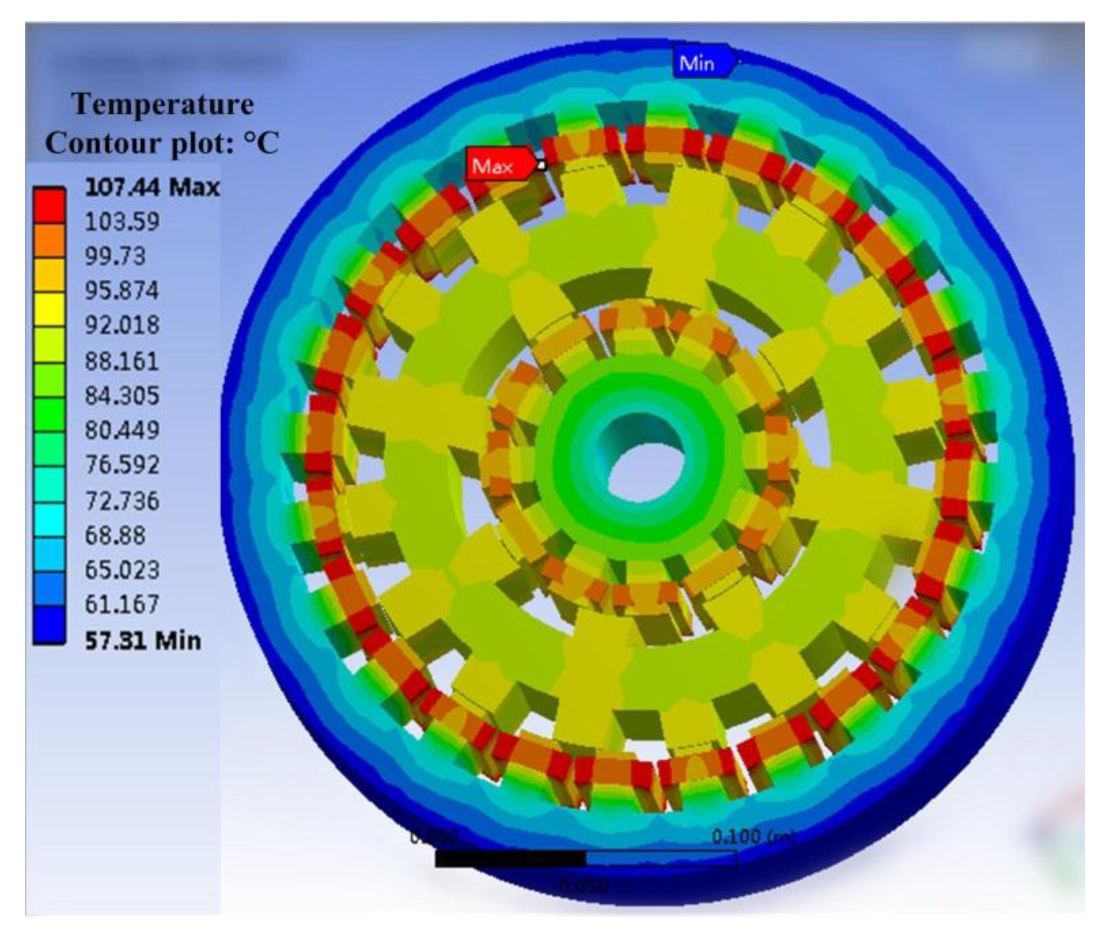
Section 4, where multi-physical field analysis is obtained successfully, including the study of mechanical stress, deformation of the middle rotor, and temperature distribution of the proposed motor. Finally, conclusions are drawn in Section 5.

2. Motor Structure and Operating Principle

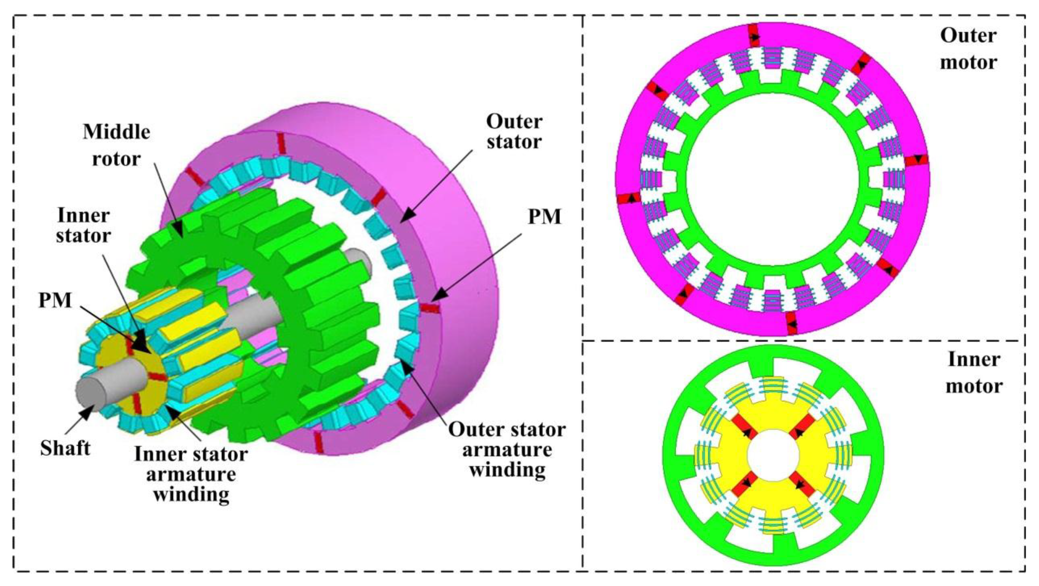
Figure 1 depicts the topology of the DS-PMDS motor, where three parts of the outer stator, middle rotor and inner stator are involved. First, as shown in the figure, the two stators and the middle rotor make up the salient pole structure. The middle rotor is sandwiched by the outer and inner stator. The winding housed in the outer stator couples with the middle rotor, comprising a 24-slot/16-pole outer motor. Meanwhile, a 12-slot/8-pole inner motor is formed through the middle rotor and the inner stator. Since there are neither permanent magnets nor windings in the middle rotor, it results in a simple and reliable rotor structure, which is similar to that of the stator permanent magnet motor. Furthermore, the yoke of both stators contains tangential magnetized permanent magnets. The armature windings in both stators are non-overlapping concentrated windings, which can lead to the reduction of copper loss and a relatively higher efficiency. Finally, it is evident that the internal space of the machine is efficiently used by adding the inner stator, which offers the possibility to improve power and torque levels.
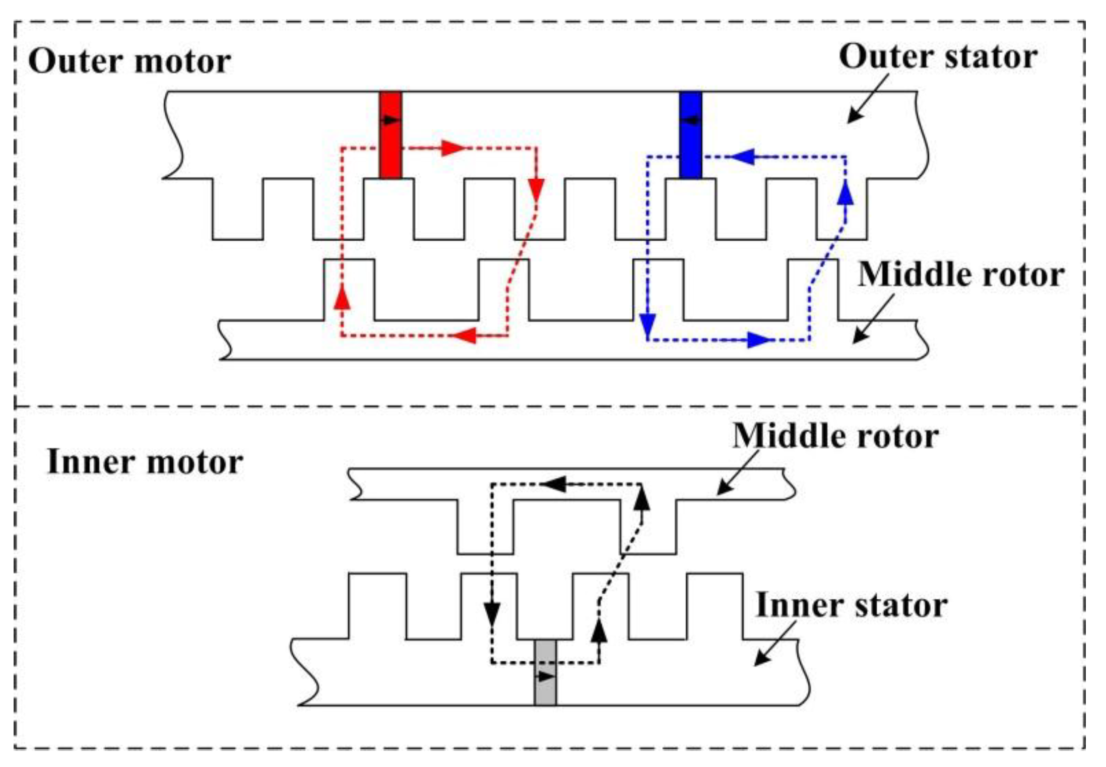
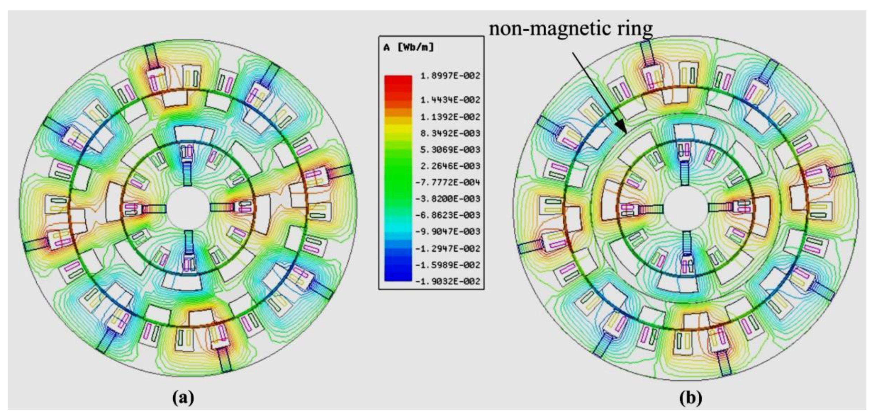
Figure 2 shows the operating principle of the DS-PMDS motor, in which the magnetic field distribution follows the principle of minimum magnetic resistance [12]. To reduce the electromagnetic coupling degree of the inner and outer motors, a non-magnetic ring is added to the middle rotor. Consequently, the magnetic circuit of the inner motor and the outer motor is parallel with low magnetic coupling degree, which makes control of the inner and outer motors more flexible and offers flexible switching between multiple driving modes of the DS-PMDS motor.
Generally, the driving cycles of vehicles are complex and changeable in actual road conditions. As shown in Figure 3, the new European driving cycle (NEDC) contains several typical driving cycle units [13]. These driving conditions includes frequent start and stop, normal and high-speed cruise, acceleration and deceleration, and climbing with heavy load. Hence, multi-operating modes are required for the EV traction motor to meet the various requirements of driving cycle conditions. Owing to the two sets of armature windings, the proposed DS-PMDS motor has a variety of operating modes and can be flexibly switched to suit different working conditions. 
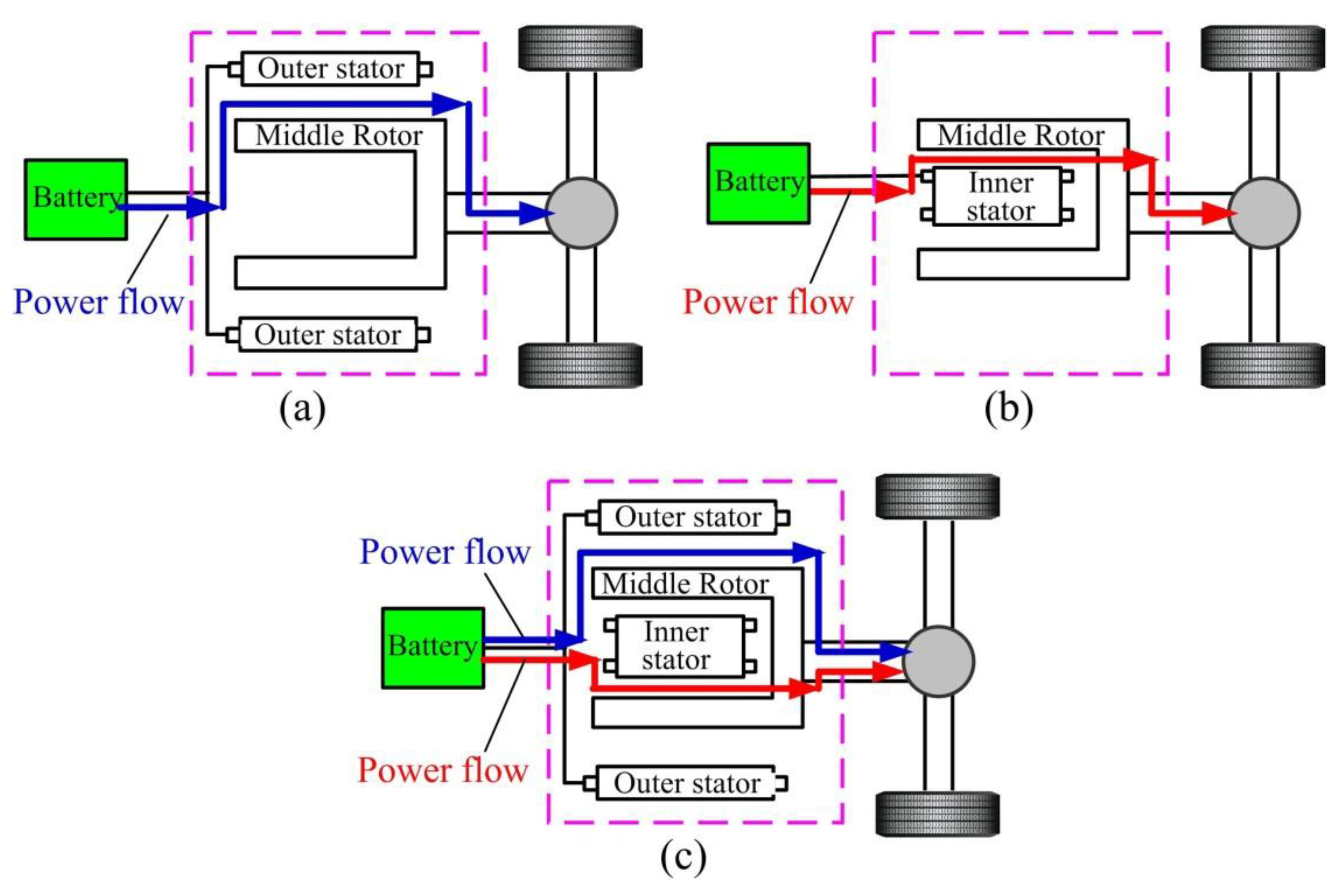
Figure 4 illustrates the corresponding powertrain, based on the DS-PMDS motor in EVs [14].
Using two sets of windings and converters, power transmission is realized from the battery to the inner and outer motors. Both motors then drive the middle rotor, which is connected to the final driveline. Based on the law of electromechanical energy conversion, the output torque of the DS-PMDS motor can be further expressed as:
T output T load = J d ω d t = G D 2 375 d n d t
T output = k 1 ( i inner ) T inner + k 2 ( i outer ) T outer
where Toutput is the total output torque of the DS-PMDS motor. Tload is the vehicle load torque, which varies with driving conditions. J is the total moment of inertia of the DS-PMDS motor. ω (rad/s) and n (rpm) are rotation angular velocity and speed of the motor, respectively. G is the weight of the middle rotor. D is the outer diameter of the intermediate rotor. Tinner and Touter are torque of inner motor and outer motor. iinner and iouter are phase current of inner and outer motor. The coefficients k1 and k2 are functions of the phase current of the inner and outer motors, respectively. Therefore, according to different requirements of load torque, the drive mode of the DS-PMDS motor can be flexibly switched by controlling the current of the two sets of windings.
For the DS-PMDS motor to satisfy different driving cycle conditions, the control coefficients k1 and k2 are adjusted accordingly to switch the operating mode of the motor; this is listed in Table 1 in detail. When the vehicle is in normal cruise or deceleration driving cycle, the power required is relatively low. Consequently, the independent drive mode of the inner motor with 0 ≤ k1 ≤ 1, k2 = 0 can be adopted to meet the required driving power. When the EV is in high-speed cruise, the low torque output of the inner motor cannot meet driving requirements. Thus, to obtain the desired speed and torque output, the outer motor drive mode is adopted with 0 ≤ k2 ≤ 1, k1 = 0. For climbing, starting and acceleration, the demand for power and torque is further enhanced. At this point, the dual drive mode is required to obtain higher output power and torque.

3. Multi-Objective Design Optimization

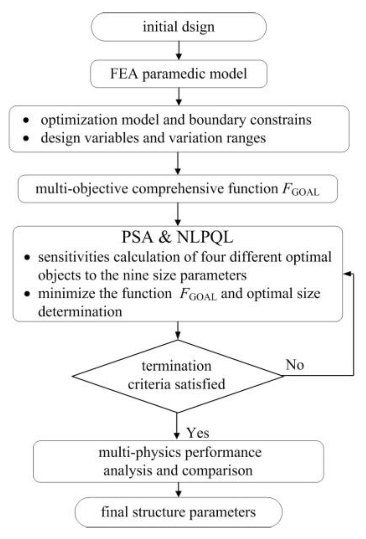
For the proposed DS-PMDS motor, due to its complex configuration with a large number of design variables, the conventional optimal design method that often uses discrete parameter scanning for single objective cannot be effectively applied. Besides, based on the above analysis, the proposed operating modes make the multi-objective optimization design of the motor more complicated. To achieve higher PM material utilization ratio and motor efficiency, higher torque output with lower torque ripple, an effective multi-objective optimization strategy is implemented and introduced in detail in this paper [15,16]. A multi-objective comprehensive function in design strategy is established. Then, by adopting parametric sensitivity analysis (PSA) and the sequential quadratic programming (NLPQL) method, the influence extent of each design parameter for different design objectives is effectively evaluated and the optimal results are determined. The flow diagram of the proposed optimal design is shown in Figure 5.

3.1. Optimization Model

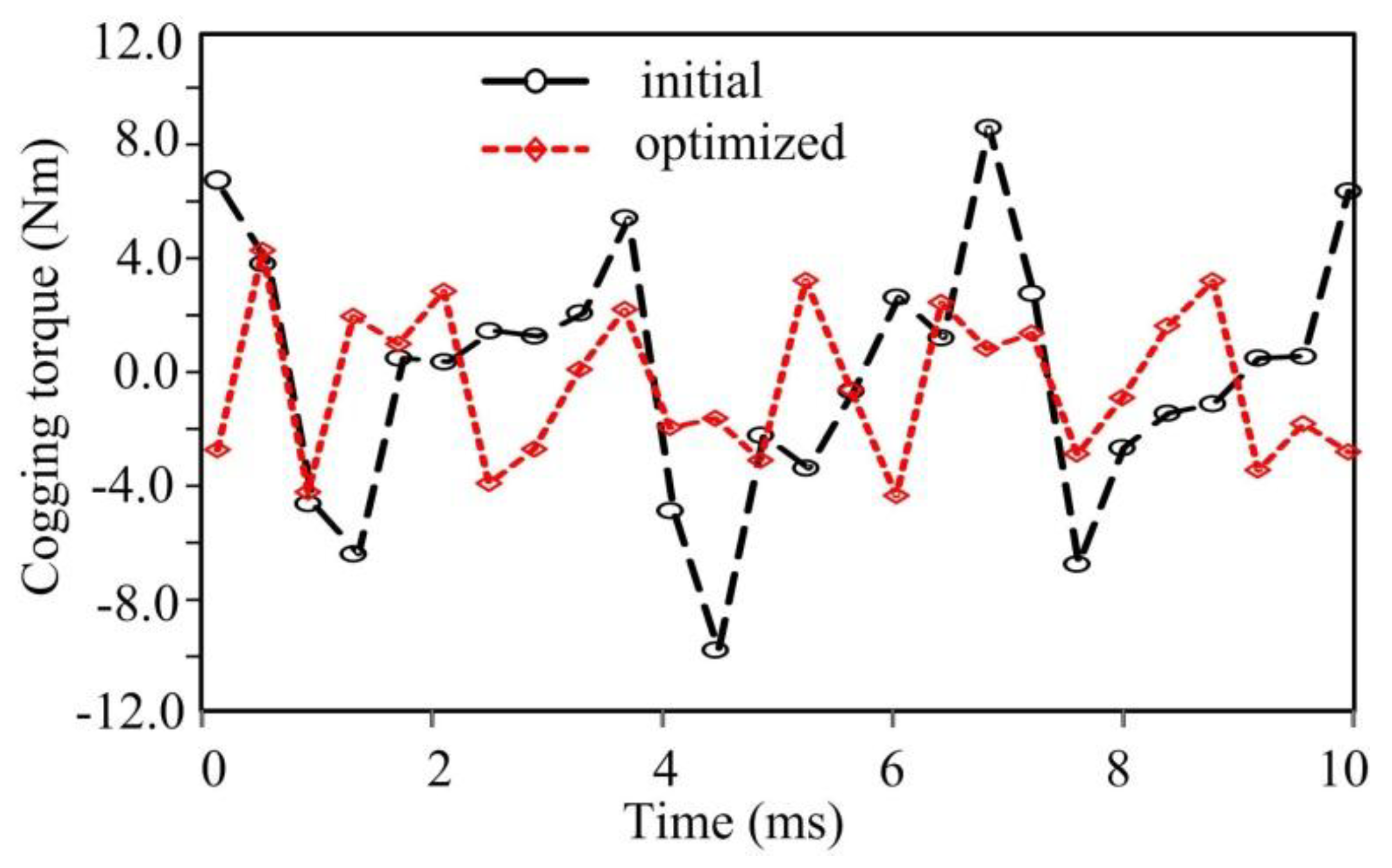
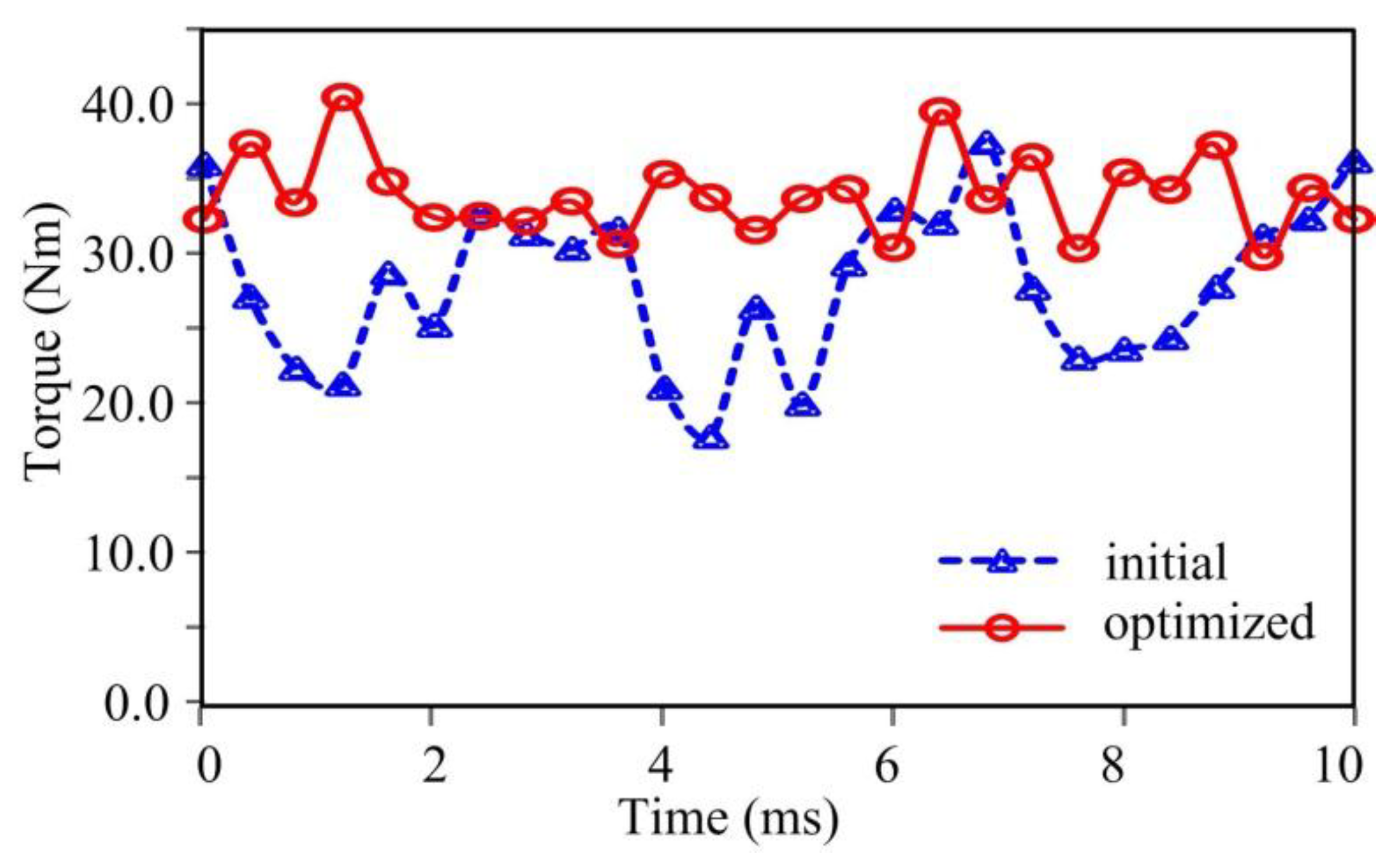
As the DS-PMDS motor has a double-salient structure, low cogging torque needs to be first considered. In addition, as a traction motor, high torque output is the preferable design requirement to meet the vehicle’s multiple operation conditions of acceleration, deceleration and overload climbing conditions. Moreover, the performances of high PM material utilization ratio and motor efficiency are also required to be satisfied. Consequently, the optimization model of DS-PMDS motor can be presented as:
f(xi) = { Tm (xi)max, Tri (xi)min, δPM(xi)max, η(xi)max }
According to the potential application area in EVs, the added boundary constraints are given as design examples:
{ T m 28 Nm T r i 50 % η 90 %
where, Tm is average output torque, Tri is torque ripple, δPM is PM material utilization ratio (which is defined as the ratio of output torque to PM volume), η is motor efficiency, xi is the vector of the optimization parameters, which can be written as:
x ( i ) = [ x 1 x 2 x 3 x 4 x 5 x 6 x 7 x 8 x 9 ] = [ h i P M δ i β r i h r y β r o δ o β o s h o P M β i s ]
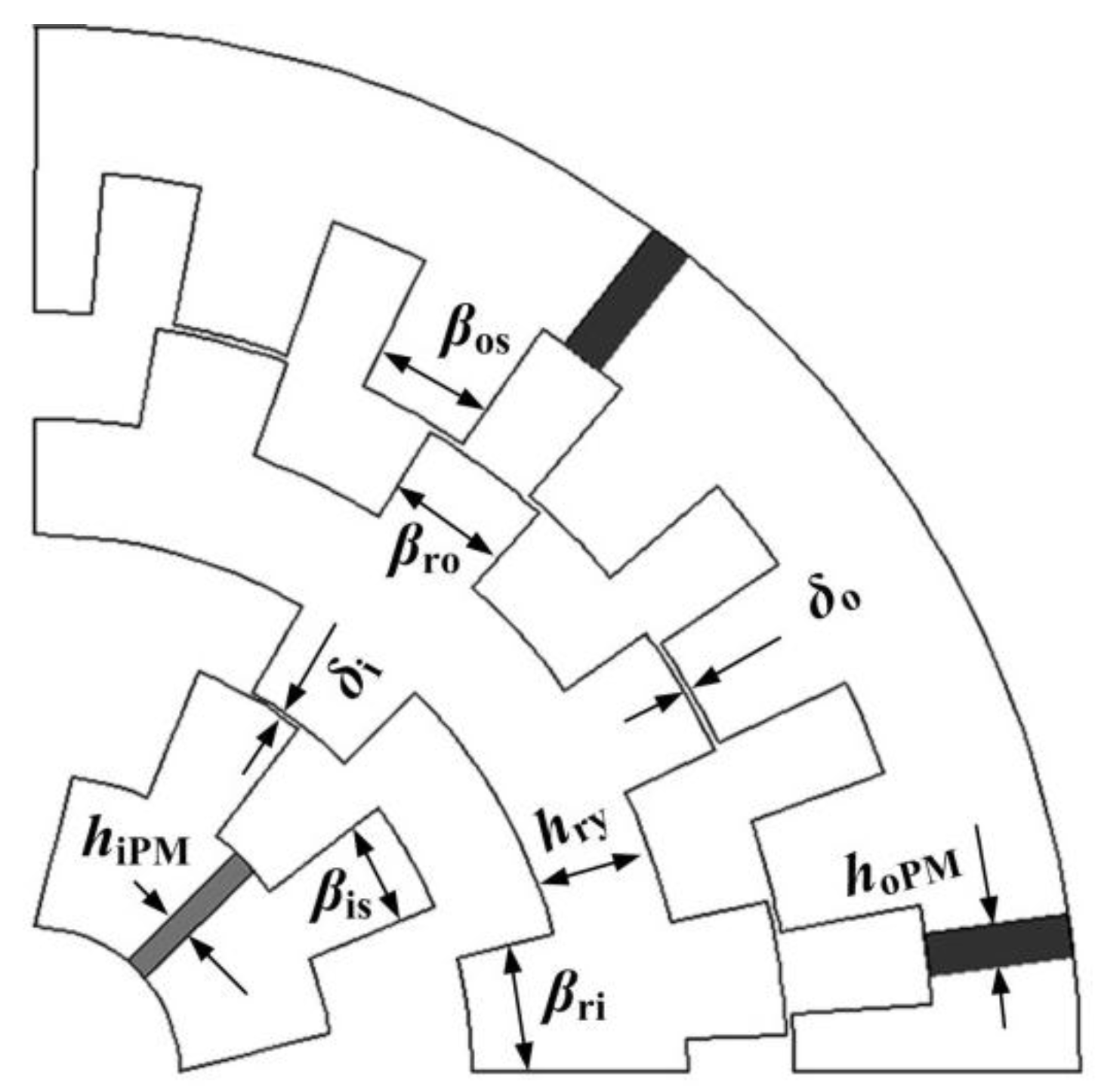
Figure 6 shows the selected nine design variables, which are several in number owing to the structure of a double-stator. The main dimensions are: magnetic thickness of the PM in outer stator hoPM and magnetic thickness of PM in inner stator hiPM. δo and δi are outer and inner air gaps, respectively. βis, βos, βro and βri is the tooth width of the inner stator, outer stator and middle rotor. hry is the middle rotor yoke height. In order to simplify the multi-objective optimization calculation and consider feasibility of manufacturing, the constraint ranges of these parameters are listed in Table 2.

3.2. Multi-Objective Comprehensive Function

From the above, there are several goals in the optimization model of the DS-PMDS motor. To reduce the conflict of multiple targets, we simplify the complication of trade-off analysis and improve the multi-objective optimization efficiency; the comprehensive objective function of the DS-PMDS motor is built as follows:
F GOAL = λ 1 T ri ( x i ) T ri + λ 2 T m T m ( x i ) + λ 3 η η ( x i ) + λ 4 δ PM δ PM ( x i )
where, Tri, Tm, η′ and δPM′ are the initial values of the torque ripple, output torque, efficiency and PM material utilization ratio, respectively; Tri(xi), Tm(xi), η(xi) and δPM(xi) are the functions of the design variables of xi; λ1, λ2, λ3 and λ4 are the four weight coefficients that need to meet the relationship of λ1 + λ2 + λ3 + λ4 = 1 and here the values are 0.3, 0.3, 0.2 and 0.2 separately.

3.3. Parameters Sensitivity Analysis and Multi-Objective Optimization

After the comprehensive objective function is proposed in Equation (6), the multi-objective optimization with tradeoff analysis is implemented, where high-dimension calculation and a time-consuming optimization process is involved. To simplify the multi-objective optimization of the proposed complex motor, the PSA approach is used, integrating multiple optimization targets to obtain a global optimal solution, intuitively and efficiently. Besides, in this way, the sensitivity of each parameter to various optimal goals can also be identified and the key size parameters can be easily selected to improve the efficiency of further optimization and adjustment.
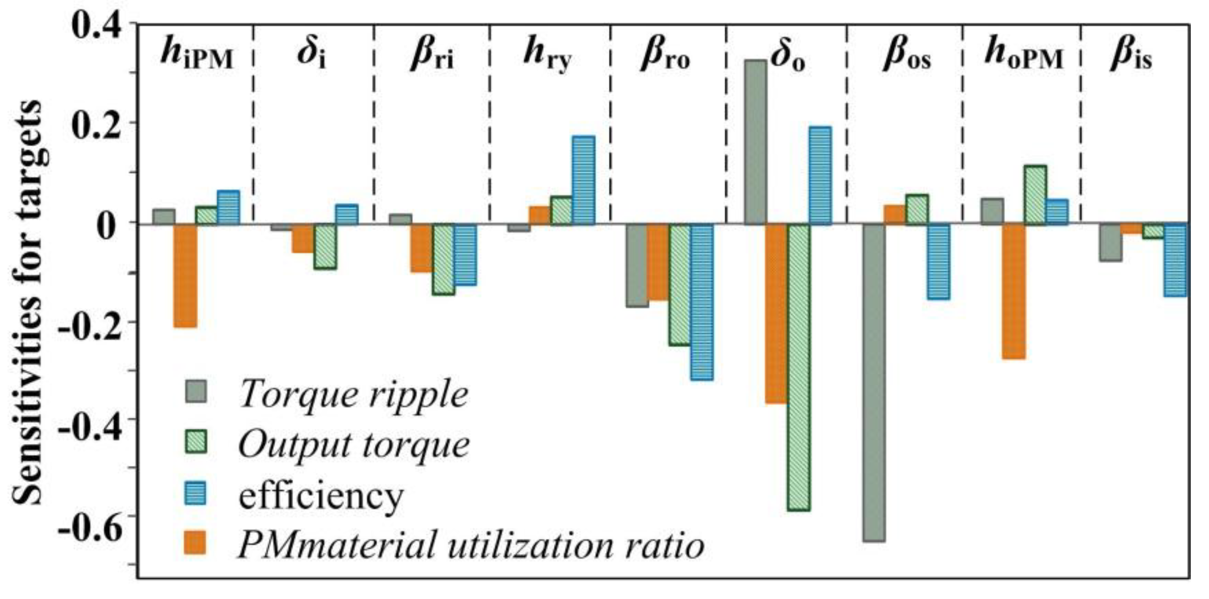
Figure 7 shows the sensitivities of four optimal objects to the nine design variables, taking into consideration the interaction among the different design parameters. Several conflicts exist among the four design objectives. The most critical design parameters affecting Tri, Tm, η and δPM are the outer stator tooth width βos, the outer air gap δo, the outer tooth width of middle rotor βro, and the magnetized thickness of PM in outer stator 
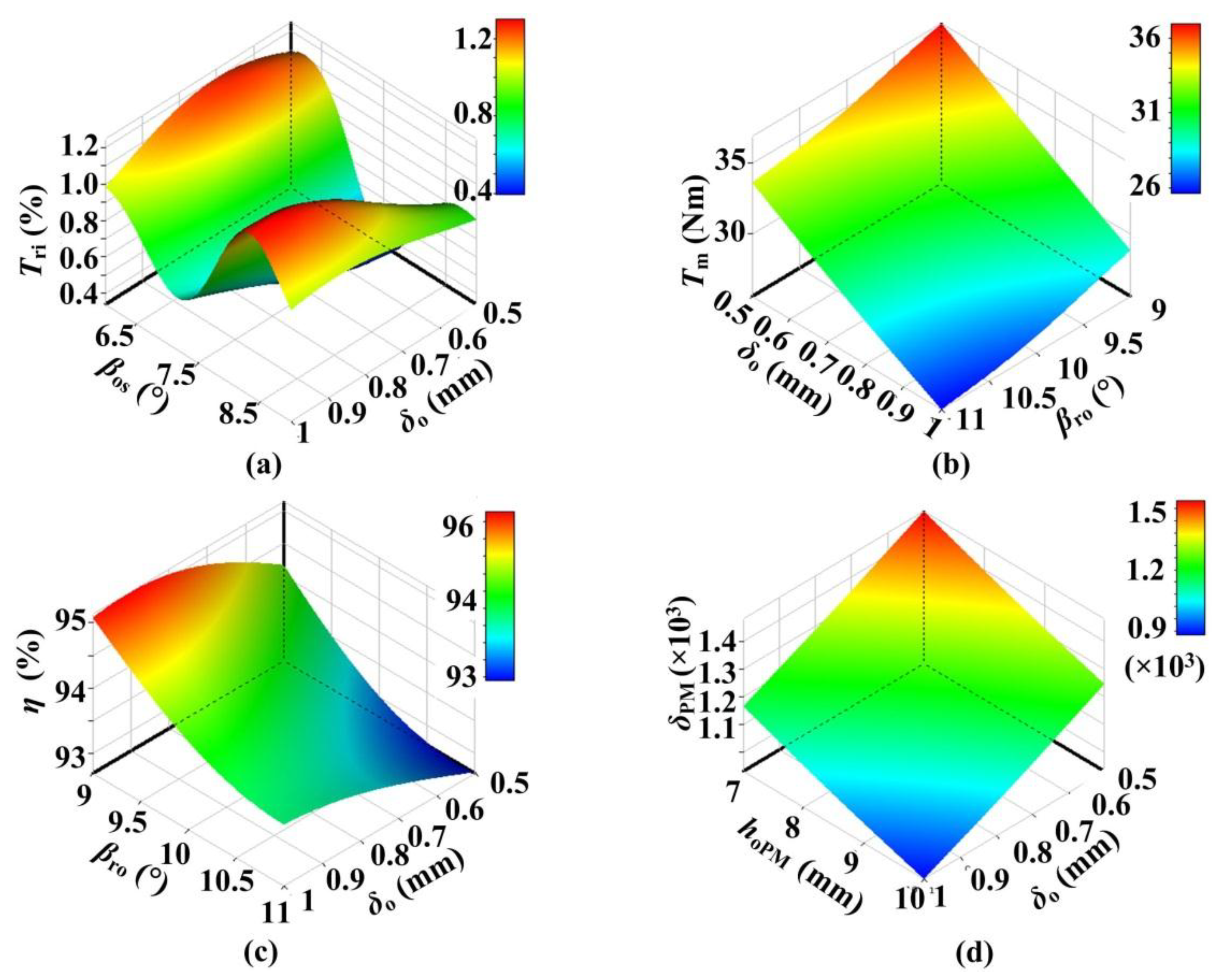
hoPM. The three-dimensional response surface between four targets and nine chosen design parameters can be also obtained; the four typical ones are shown in Figure 8. The above two figures show that the high sensitivity parameters are different for various application requirements and optimization targets, and different key parameters can be conveniently chosen to further optimization and adjustment.
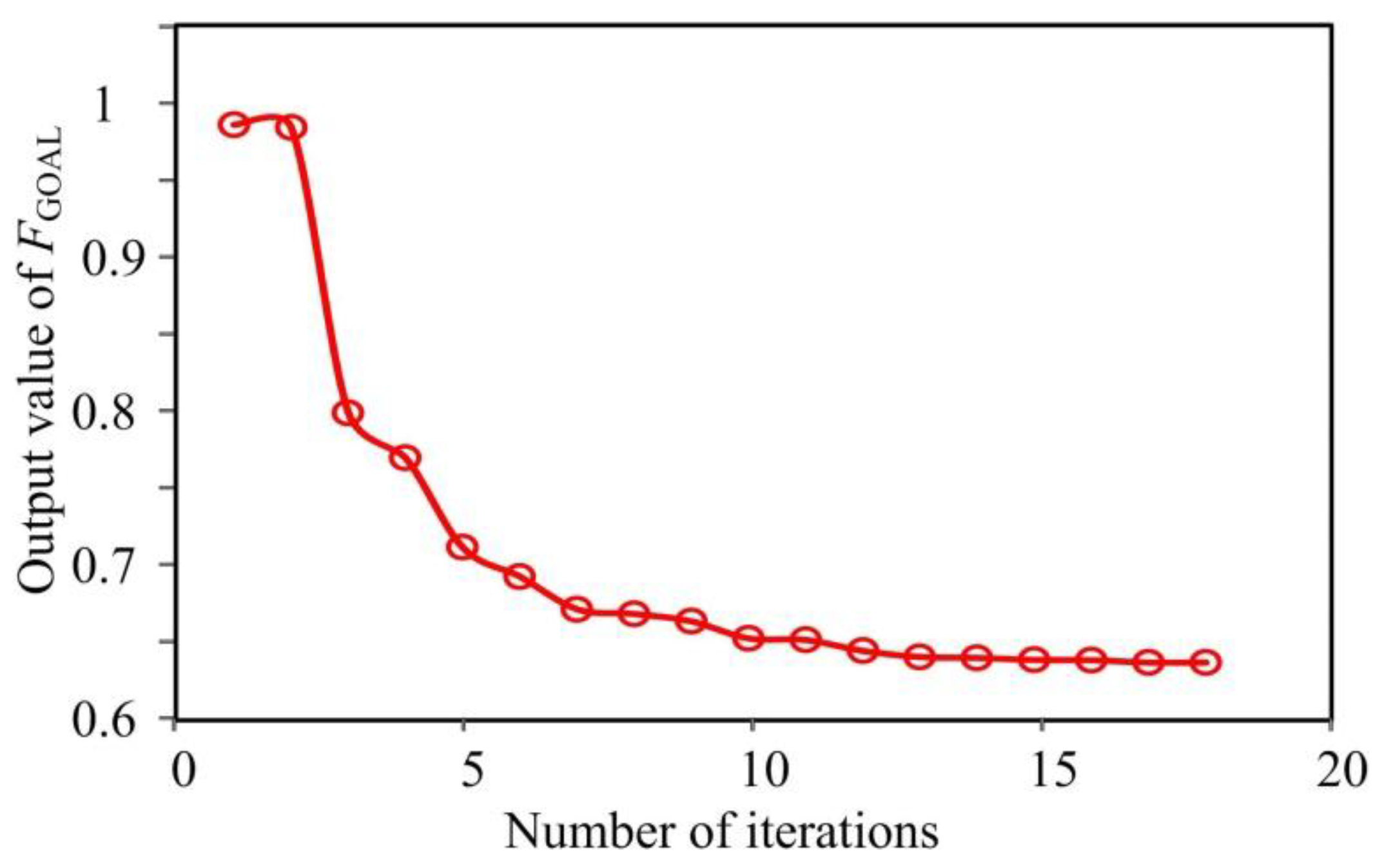
Based on the defined multi-objective comprehensive function FGOAL in Equation (6), Figure 9 shows the effects of nine design parameters on comprehensive objective function FGOAL. In addition, as shown in Figure 10, based on the NLPQL approach, after 17 generations of iterative optimization, the optimal solution for the comprehensive objective function FGOAL can be efficiently achieved. An optimal tradeoff can be obtained for engineering practice, based on comprehensive objective function and special boundary conditions. The corresponding optimal results of FGOAL, the four optimization targets, and nine design parameters are listed in Table 3.

4. Performance Analysis on DS-PMDS Motor

4.1. Flux Distributions

Figure 11 shows the flux distribution of the proposed DS-PMDS motor, with and without a non-magnetic ring. It can be observed from Figure 11a that when all the PMs in the two stators work together, some flux lines are always directly closed, without passing through the middle rotor. That is, in addition to the parallel main magnetic circuit, there is also a series magnetic circuit, and the electromagnetic coupling degree of the inner and outer motors is relatively high. When the non-magnetic ring is added, it can be seen from Figure 11b that the main magnetic circuit of the inner motor and the outer motor is parallel. The electromagnetic coupling degree of the inner motor and the outer motor is then obviously decreased, which is consistent with the previous theoretical analysis.

4.2. No-Load Back EMF

The no-load back EMF of the DS-PMDS motor is studied in this paper, considering that the no-load back EMF directly affects the output torque performance of the motor. For two sets of armature windings, at the rated speed of 750 r/min, the no-load phase EMF waveforms and their harmonic spectrum are compared, before and after optimization, as shown in Figure 12 and Figure 13. It was found that the performance of the no-load back EMF was improved. Figure 12a and Figure 13a show that, compared to the back EMF of the inner winding, the amplitude of the back EMF of the outer winding increases more obviously from 142.3 V to 155.8 V, indicating the enhancement of output torque and proving the validity of the motor optimization method. In addition, as shown in Figure 12b and Figure 13b, after optimization, both inner and outer windings have more sinusoidal back EMF waveforms with decreased low harmonic content. The high sinusoidal back EMF does not only lay a good foundation for the subsequent reduction of torque ripple, but also indirectly verifies the effectiveness of torque ripple optimization of the motor.

4.3. Core Loss and Efficiency

The loss of motor directly affects efficiency; this is analyzed in this section. Core loss is the main component of no-load loss of the DS-PMDS motor. It can be estimated by the following model [17]:
P s = k e f 2 B m 2 + k h f 2 B m 2
where Ps is the core less of the motor, ke and kh, respectively, represent the eddy current and hysteresis loss coefficients. f is the frequency of sinusoidal alternating flux density. Bm is the amplitude of flux density.
Figure 14 shows the no-load core loss distribution of the proposed machine. It can be seen that the core loss distribution is not uniform in the outer stator, middle rotor and inner stator. In areas with high magnetic flux density, such as the tip where the stator and rotor overlap and the yoke of the middle rotor, core loss is relatively high. As shown in Figure 15, after the optimization and adjustment of some key size parameters, core loss decreased under different rotating speed conditions. When the rated speed was 750 rpm, the average of core loss decreased from 59.94 W to 34.42 W, which is conducive to improvement of motor efficiency.

4.4. Torque Capability

Figure 16, Figure 17 and Figure 18 shows comparisons of torque capability. As illustrated in Figure 16, the cogging torque peak values of the optimized machine are respectively smaller than those of the initial design. Figure 17 shows the output torque waveform at the rated speed when the amplitude of phase current is 8 A. After optimization and adjustment, the average output torque increased by 15%, while torque ripple reduced by 42%. From Figure 18, it is evident that the optimized motor has a higher torque output capability. This study found that the proposed optimization method can significantly improve torque performance.

4.5. Structural Analysis

As the proposed DS-PMDS motor has a special structure with double air gap and cupped rotor, a structural simulation is implemented to identify the stress caused by centrifugal forces and verify the structural robustness of the designed rotor [18,19]. Figure 19 shows the 2D stress distribution of the middle rotor when the motor speed reaches 10,000 r/min. As can be seen from the figure, the stress distribution is not uniform. Since the mass distribution of the rotor is not uniform and the yoke of the middle rotor is relatively narrow, the maximum stress appears at the yoke part of the middle rotor, which is 126.5 MPa and less than the stress limit of the material. In addition, simulation results for deformation of the DS-PMDS motor is shown in Figure 20. It was observed that under a maximum speed of 10,000 rpm, the maximum deformation of the rotor is no more than 0.05 mm, which is also within safe operating limits.

4.6. Thermal Analysis

The heat flow in the optimal DSPM is analyzed based on the electromagnetic-thermal coupling method [20,21]. Initially, internal heat generation in the motor is obtained by the calculation of total losses, which is then imported to steady-state thermal analysis. During this electromagnetic thermal coupling simulation, key parameters such as heat source, residual magnetic flux density and intrinsic coercive force are updated in real time. In the process of the analysis, the boundary condition of stator housing is set to a temperature of 40 °C with water cooling. The general thermal field distribution and the temperature of every part of the motor is calculated successfully and shown in Figure 21. The outer armature winding reaches the maximum temperature of 107.44 °C, which is still within the acceptable range due to proper water cooling measures. The PMs in the inner and outer stators are at about 80 °C and 65 °C, respectively. They are both lower than the maximum allowable working temperature, avoiding demagnetization of the PMs caused by high temperature.

5. Conclusions

In this paper, a multi-objective optimization design procedure with multi-physics field analysis is presented to provide comprehensive optimization of a new type of DS-PMDS motor. Firstly, a multi-objective function is established. Secondly, a design optimization method using parametric sensitivity analysis (PSA) and sequential quadratic programming (NLPQL) is discussed in detail. The significance of the parameters is also effectively evaluated and the optimal structure size parameters are determined. The performance of the proposed DS-PMDS motor, including electromagnetism, structure and heat, is then calculated by multi-physics field analysis. Finally, the proposed machine is shown to offer good electromagnetic performance characteristics of high output torque, low torque ripple and high efficiency. The simulation results of stress and deformation verify the robust rotor structure. The thermal analysis also shows that the proposed DS-PMDS motor can operate at a reasonable temperature. Both the theoretical analysis and multi-physics field simulation verify the validity of the motor design and the effectiveness of the proposed optimization method.

Author Contributions

Y.C. is the main author, who provided the research ideas and methods. Y.D. and J.Z. assisted in the implementation of the research and produced the diagrams. X.Z. provided constructive suggestions for the construction of this article. All the authors made a significant contribution to the work.

Funding

This research was funded by [National Natural Science Foundation of China] grant number [51507151] and [Natural Science Foundation of the Jiangsu] grant number [BK20150454].

Conflicts of Interest

The authors declare no conflict of interest.

References

  1. Chau, K.T.; Chan, C.C.; Liu, C. Overview of permanent- magnet brushless drives for electric and hybrid electric vehicles. IEEE Trans. Ind. Electron. 2008, 55, 2246–2257. [Google Scholar] [CrossRef] [Green Version]
  2. Hua, W.; Su, P.; Tong, M.H.; Meng, J.J. Investigation of a five-phase E-core hybrid-excitation flux-switching machine for EV and HEV applications. IEEE Trans. Ind. Appl. 2017, 53, 124–133. [Google Scholar] [CrossRef]
  3. Du, Y.; Yang, G.; Quan, L.; Zhu, X.Y.; Xiao, F.; Wu, H.Y. Detent force reduction of a C-core linear flux-switching permanent magnet machine with multiple additional teeth. Energies 2017, 10, 318. [Google Scholar] [CrossRef]
  4. Xu, W.; He, M.J. Novel 6/7 stator/rotor hybrid excitation doubly salient permanent magnet machine. IEEE Trans. Magn. 2016, 52, 8106405. [Google Scholar] [CrossRef]
  5. Chen, Y.Y.; Li, Q.; Zhu, X.Y. Electromagnetic performance analysis of double-rotor stator permanent magnet motor for hybrid electric vehicle. IEEE Trans. Magn. 2012, 48, 4204–4207. [Google Scholar]
  6. Zhang, G.; Hua, W.; Cheng, M. Design and comparison of two six-phase hybrid-excited flux-switching machines for EV/HEV applications. IEEE Trans. Ind. Appl. 2016, 63, 481–493. [Google Scholar] [CrossRef]
  7. Shi, Y.J.; Jian, L.N. A novel dual-permanent-magnet-excited machine with flux strengthening effect for low-speed large-torque applications. Energies 2018, 11, 153. [Google Scholar] [CrossRef]
  8. Du, Z.S.; Lipo, T.A. An improved rotor design for dual-stator vernier ferrite permanent magnet machines. In Proceedings of the 2017 IEEE International Electric Machines and Drives Conference (IEMDC), Miami, FL, USA, 21–24 May 2017. [Google Scholar]
  9. Wang, Y.B.; Cheng, M.; Chen, M.; Du, Y.; Chau, K.T. Design of high-torque-density double-stator permanent magnet brushless motors. IET Electr. Power Appl. 2011, 5, 317–323. [Google Scholar] [CrossRef]
  10. Zhu, X.Y.; Xiang, Z.X.; Quan, L.; Wu, W.Y.; Du, Y. Multi-Mode optimization design methodology for a flux-controllable stator permanent magnet memory motor considerin g driving cycles. IEEE Trans. Ind. Electron. 2018, 65, 5353–5366. [Google Scholar] [CrossRef]
  11. Jia, H.; Cheng, M.; Hua, W. Torque ripple suppression in flux-switching PM motor by harmonic current injection based on voltage space-vector modulation. IEEE Trans. Magn. 2010, 46, 1527–1530. [Google Scholar] [CrossRef]
  12. Zulu, A.; Mecrow, B.; Armstrong, M. A wound-field three-phase flux switching synchronous motor with all excitation sources on the stator. IEEE Trans. Ind. Appl. 2010, 46, 2363–2371. [Google Scholar] [CrossRef]
  13. Wang, J.; Yuan, X.; Atallah, K. Design optimization of a surface-mounted permanent-magnet motor with concentrated windings for electric vehicle applications. IEEE Trans. Veh. Technol. 2013, 62, 1053–1064. [Google Scholar] [CrossRef]
  14. Xiang, Z.X.; Zhu, X.Y.; Quan, L.; Du, Y.; Zhang, C.; Fan, D.Y. Multilevel design optimization and operation of a brushless double mechanical port flux-switching permanent-magnet motor. IEEE Trans. Ind. Electron. 2016, 63, 6042–6054. [Google Scholar] [CrossRef]
  15. Zhu, X.; Xiang, Z.; Quan, L.; Chen, Y.; Mo, L. Multi-mode optimization research on a multi-port magnetic planetary gear permanent magnet machine for hybrid electric vehicles. IEEE Trans. Ind. Electron. 2018, 65, 9035–9046. [Google Scholar] [CrossRef]
  16. Lei, G.; Wang, T.; Zhu, J.G.; Guo, Y.G.; Wang, S.H. System-level design optimization method for electrical drive systems-robust approach. IEEE Trans. Ind. Electron. 2015, 62, 4702–4713. [Google Scholar] [CrossRef]
  17. Zhu, X.; Huang, J.; Quan, L.; Xiang, Z.; Shi, B. Comprehensive sensitivity analysis and multi-objective optimization research of permanent magnet flux-intensifying motors. IEEE Trans. Ind. Electron. 2018. [Google Scholar] [CrossRef]
  18. Sun, X.; Cheng, M.; Zhu, S.; Zhang, J. Coupled electromagnetic-thermal-mechanical analysis for accurate prediction of dual-Mechanical-port machine performance. IEEE Trans. Ind. Appl. 2012, 48, 2240–2248. [Google Scholar] [CrossRef]
  19. Bonthu, S.S.R.; Choi, S.; Baek, J. Design optimization with multiphysics analysis on external rotor permanent magnet-assisted synchronous reluctance motors. IEEE Trans. Ener. Conver. 2018, 33, 290–298. [Google Scholar] [CrossRef]
  20. Chen, Y.; Zhu, X.; Quan, L.; Wang, L. Performance Analysis of a double-salient permanent-magnet double-rotor motor using electromagnetic-thermal coupling method. IEEE Trans. Appl. Supercond. 2016, 26, 1–5. [Google Scholar] [CrossRef]
  21. Shu, Z.M.; Zhu, X.Y.; Quan, L.; Du, Y.; Liu, C. Electromagnetic Performance Evaluation of an Outer-Rotor Flux-Switching Permanent Magnet Motor Based on Electrical-Thermal Two-Way Coupling Method. Energies 2017, 10, 677. [Google Scholar] [CrossRef]
Figure 1. Structure of the DS-PMDS motor.
Energies 11 02130 g001
Figure 2. Operation principle of the DS-PMDS motor.
Energies 11 02130 g002
Figure 3. Various driving modes of the DS-PMDS motor in EV.
Energies 11 02130 g003
Figure 4. Various driving modes of the DS-PMDS motor in EV. (a) Outer motor drive mode. (b) Inner motor drive mode. (c) Dual drive mode.
Energies 11 02130 g004
Figure 5. Flow diagram describing an optimal design procedure.
Energies 11 02130 g005
Figure 6. Dimensional parameter model.
Energies 11 02130 g006
Figure 7. Sensitivity analysis results.
Energies 11 02130 g007
Figure 8. Response of four optimal objects with different key parameters: (a) Response of Tri with βos and δo; (b) Response of Tm in δo and Bro; (c) Response of η in δo and Bro; (d) Response of δPM in δo and hoPM.
Energies 11 02130 g008
Figure 9. Sensitivity distribution of FGOAL with size parameters.
Energies 11 02130 g009
Figure 10. The optimization results.
Energies 11 02130 g010
Figure 11. Flux distributions of the proposed machine (a) without non-magnetic ring, (b) with non-magnetic ring.
Energies 11 02130 g011
Figure 12. Back EMF comparison of the outer motor (a) back EMF waveforms of outer phase winding; (b) back EMF harmonic spectra of outer phase winding.
Energies 11 02130 g012
Figure 13. Back EMF comparison of the inner motor (a) back EMF waveforms of inner phase winding; (b) back EMF harmonic spectra of inner phase winding.
Energies 11 02130 g013
Figure 14. Core loss distribution.
Energies 11 02130 g014
Figure 15. Core loss versus speed waveforms.
Energies 11 02130 g015
Figure 16. Cogging torque waveforms.
Energies 11 02130 g016
Figure 17. Rated steady state torque waveform.
Energies 11 02130 g017
Figure 18. The static torque versus current waveforms.
Energies 11 02130 g018
Figure 19. Simulation results for equivalent stress of DS-PMDS motor.
Energies 11 02130 g019
Figure 20. Simulation results for deformation of DS-PMDS motor.
Energies 11 02130 g020
Figure 21. 3D simulation results of the general thermal field distribution of the motor.
Energies 11 02130 g021
Table 1. Relationship among Vehicle Driving Cycles, Operating Modes and Control Coefficients.
Driving Cycle ConditionsOperating ModesControl CoefficientKey Design Requirements
Normal cruise
Deceleration
Inner motor drive mode 0 ≤ k1 ≤ 1, k2 = 0Low torque ripple
High-speed cruiseOuter motor drive mode0 ≤ k2 ≤ 1, k1 = 0High efficiency
Starting, Climbing
Acceleration
Dual drive mode0 ≤ k1 ≤ 1,
0 ≤ k2 ≤ 1
High torque
High PM material utilization
Table 2. Range of Optimal Variables.
Optimization VariablesConstraint Ranges
Inner stator tooth width (βis)14.5–20°
Outer stator tooth width (βos)6–9°
Outer air gap (δo)0.5 mm–1 mm
Middle rotor yoke height (hry)16 mm–20 mm
Outer tooth width of middle rotor (βro)9°–11°
Inner tooth width of middle rotor (βri)14°–20°
Inner air gap (δi)0.5 mm–1 mm
Mag. thick of PM in outer stator (hoPM)7 mm–10 mm
Mag. thick of PM in inner stator (hiPM)5 mm–9 mm
Table 3. Optimal Results.
ItemsInitial ValuesOptimal Values
βis (°)15.517.3
βos (°)7.57.5
δo (mm)0.80.5
hry (mm)1618
βro (°)11.510
βri (°)1516.5
δi (mm)0.80.8
hoPM (mm)87.7
hiPM (mm)76.5
Tri (%)58.633.5
Tm (Nm)28.733.6
η (%)93.395.2
δPM (Nm/mm3)11681425
FGOAL10.633

