Article

Decentralized Circulating Currents Suppression for Paralleled Inverters in Microgrids Using Adaptive Virtual Inductances

1
Key Laboratory of Complex System Safety and Control, Ministry of Education, Chongqing University, Chongqing 400044, China
2
College of Automation, Chongqing University, Chongqing 400044, China
*
Author to whom correspondence should be addressed.
Energies 2018, 11(7), 1725; https://doi.org/10.3390/en11071725
Submission received: 23 May 2018 / Revised: 20 June 2018 / Accepted: 25 June 2018 / Published: 2 July 2018
(This article belongs to the Section F: Electrical Engineering)

Abstract

:
Droop-controlled inverters, which are the main interfaces between distributed generators (DGs) and grid AC bus, are widely adopted in today’s microgrids. Because the DGs are usually dispersed along with the microgrids, which may spread out in a wide area, the impedances of transmission lines that connect different DGs and the point of common coupling (PCC) may be different. Large circulating currents among paralleled inverters would be induced eventually, which not only results in decreased system efficiency, but also makes some DGs impossible to operate at their rated power. In this paper, the relationship between circulating current and line impedances among paralleled inverters with conventional droop control is analyzed in detail. To mitigate the circulating current, an adaptive virtual output inductance control method for the DG inverter is proposed. With the help of the added adaptive virtual inductances, huge reduction on the circulating currents can be obtained regardless of the differences in line impedances. The implementation details of the proposed method and the optimum design rules for system parameters are elaborated, which are swiftly followed by the operational principle and stability analyses. Because neither communications nor global signals are needed in the proposed method, it is a total discrete approach, which evidently indicates high flexibility and scalability. The validity of the proposed method is finally verified by simulations and experiments.

1. Introduction

Microgrid, which is a promising structure to integrate renewable and distributed energy sources in a more efficient and reliable way, has greatly attracted people’s attention recently [1,2,3,4]. The microgrid is very good at improving the system’s overall efficiency, power quality, and energy surety for critical loads. It can operate in grid-connected mode or autonomous islanding mode and benefits both the utility and customers [5]. So far, many countries have devoted to develop their own microgrids to ease the integration of fast growing renewable energies to the grid, provide opportunities for economic development in electric power and clean energy industry, and most importantly obtain better power supply reliability to consumer’s loads [6,7].
In a microgrid, the micro-sources such as photovoltaic cells, small wind turbines, energy storage systems are integrated to the grid in the form of distributed generation, which are further defined as distributed generators (DGs) [8]. Typically, DGs are connected to the grid bus through inverter interfaces, or DG inverters, which operate in parallel. To ease the power control of the microgrid, droop control is usually adopted [9,10,11]. With this method, the ‘plug-and-play’ feature for the DG inverter is achieved, which ensures that the installation of new DGs will not change the control strategies of those DGs already in the microgrid. However, as DG inverters are always dispersed along with the microgrids, which may spread out in a wide area, the impedances of transmission lines that connect different DG inverters and the point of common coupling (PCC) may be different. If the conventional reactive power droop control is still adopted, accurate reactive power sharing among DG inverters can hardly be achieved as it is highly influenced by the line impedances and load characteristics [12]. Consequently, large circulating currents, which do not flow through the loads, will be induced. This not only would reduce the overall system efficiency, but also may make some DG inverters impossible to operate under their rated power conditions.
To alleviate or eliminate the influences of line impedances on the reactive power sharing, thus to mitigate the circulating currents, modifications on the conventional droop control are necessary. In [13], an accurate reactive power sharing control strategy is proposed for paralleled inverters. The distinctive feature of this method is integrated with an on-line tuning droop gain. However, as the droop gain is constantly varying, this method may suffer from stability issue. Furthermore, it should be noted that the set of droop gain in islanded mode has to use some tuned information obtained in grid-connected mode. Consequently, this method is not applicable for autonomous islanding microgrid. In [14], a robust droop control method, which adopts an integration element in the reactive power control loop, is proposed. Although this method can fully avoid the influence of line impedances, it features deteriorated flexibility and scalability due to the need of detecting voltage signal at PCC and adding complex communication system to share it with DG inverters. Some similar modified droop control methods that incorporated with integration element in the reactive power control loop can also be evidenced [15,16,17]. However, they all suffer from the same problem related to low flexibility and scalability. To address this issue, some other researchers proposed novel droop control methods, which avoid the use of common signals or communications among DGs, to mitigate the circulating currents. A new droop control method, namely reactive power–derivative of voltage droop method, is proposed to improve reactive power sharing in [18]. As derivation may amplify noises, the implementation of this method is complicated. Besides, large circulating currents can still be evidenced in the experimental results, which indicate low suppression ability. In [19], an impedance-matching method to achieve accurate reactive power sharing under unequal line impedance situation is proposed. However, it only works on condition that the DGs have equal capacities. In [20,21], virtual output inductances were added to the DG inverters by properly design the control systems. While effective in decoupling active and reactive power regulation, it is also effective in reducing the circulating currents by increasing the virtual inductances and designing them according to some optimization rules. Unfortunately, due to the lack of self-tuning ability, these virtual inductances are usually set to quite large values, which eventually cause excessive voltage drops on the AC bus. In summary, there is still a lack of a simple and flexible method to suppress the circulating currents among paralleled inverters with different capacities.
The intended contribution of this paper is to propose an adaptive virtual output inductance control method to solve the difficulty of suppressing circulating currents among paralleled inverters in the microgrid. Unlike the approaches mentioned above, as the implementation of the proposed method does not rely on any common signals or communications, high flexibility and scalability are achieved. In addition, the proposed method can be applied to paralleled inverters with different capacities. Furthermore, compared with the traditional virtual output inductances control method, the proposed method can automatically adjust the virtual inductance to better suppress circulating currents. The rest of this paper is organized as follows: the principle of the active and reactive power regulation for paralleled inverters with conventional droop control is analyzed in Section 2, in which the rationale of generation of circulating currents is discussed. In Section 3, an adaptive virtual output inductance control strategy is proposed to minimize the circulating currents. Its operational principle and implementation strategy are elaborated, followed by which the system stability and design on the system parameters are deeply studied. Afterwards, the effectiveness of the proposed control method is verified by simulation and experimental results performed by a 15 kW/4.5 kVar islanded microgrid demonstration platform in Section 4. Conclusions are finally given in Section 5.

2. Paralleled Inverters with Conventional Droop Control

2.1. Conventional Droop Control

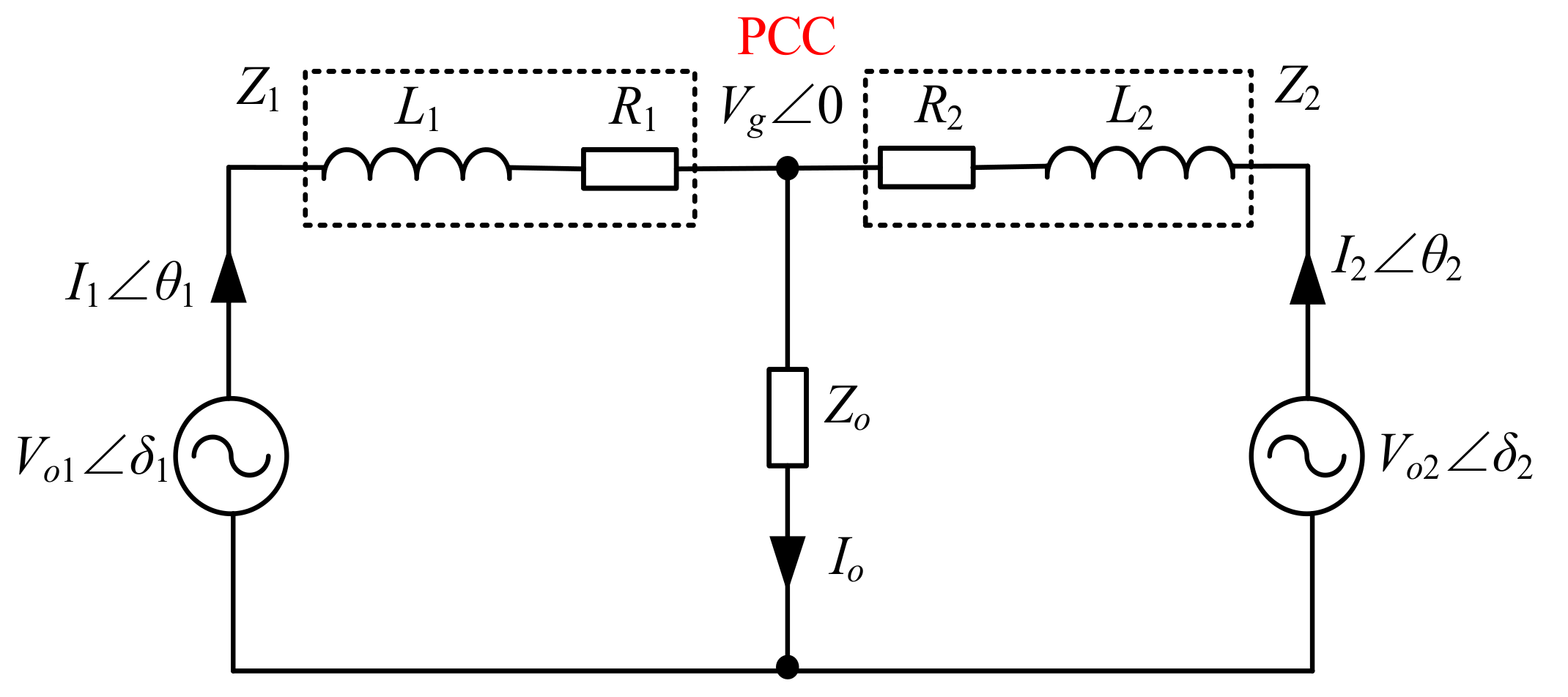
In a microgrid, DG inverters are usually paralleled. To simplify the analysis, two DG inverters connected in parallel are used as an example system throughout this paper. Figure 1 depicts the block diagram of the example system. The power capacity ratio between the two DG inverters is 1:2. The detailed system parameters are shown in Table 1 in Section 4. Figure 2 shows the equivalent circuit of the example system (one phase), in which Voiδi, Iiθi stand for the output voltage vector and output current vector of the ith DG inverter respectively, where δ is the power angle, θ is the impedance angle and i = 1, 2; Vg ∠ 0 is the voltage vector at PCC; Li and Ri are the line inductance and resistance between the output terminal of the ith DG inverter and PCC respectively; Zo and Io are the load impedance and output current (both for one phase), respectively. In particular, in the rest of this paper, subscript i is used to mark the corresponding variables of the ith DG inverter.
For the DG inverter, the active power P and reactive power Q (per phase) integrated to the microgrid can be expressed as [13],
{ P i = V o i R i 2 + X L i 2 [ R i ( V o i V g cos δ i ) + X L i V g sin δ i ] Q i = V o i R i 2 + X L i 2 [ R i V g sin δ i + X L i ( V o i V g cos δ i ) ]
In real applications, low-pass filters (LPFs) are always adopted to filter out the high-frequency harmonics in the calculated active and reactive power P and Q, the transfer function of which is,
G f i ( s ) = ω f i s + ω f i
where ωf is the corner frequency of the LPF.
In (1), as active power and reactive power are both determined by the power angle δ and the output voltage of DG inverter Vo, it is impossible to regulate the active and reactive power in a decoupled way. Therefore, large and constant virtual output inductance Lv is usually added to each DG inverter by its control system to make the system line impedance mainly inductive [20,21], i.e., (Xv + XL) >> R, where reactance Xv = ωLv and XL = ωL.
Then, the active and reactive power can be determined as,
{ P i = G f i ( s ) V o i V g δ i X i Q i = G f i ( s ) V o i ( V o i V g ) X i
where X ≈ (Xv + XL) is the equivalent line impedance after the virtual inductance added.
Equation (3) determines the basics for conventional droop control method that can be used to achieve the “plug-and-play” feature of the DG inverter, i.e., “real power versus frequency (Pω)” and “reactive power versus voltage (QV)” droop control, which is [21]
ω i = ω m i P i
V o i = V o n i Q i
where ω* and Vo* are the nominal frequency and output voltage of the DG inverter respectively; m and n are the droop coefficients for active and reactive power, respectively.
Hence, the active power and reactive power can be regulated by adjusting the frequency and output voltage respectively according to (4) and (5).

2.2. Generating of Circulating Current

Typically, it is expected that the load power can be shared by the DGs according to their own capacities. For the studied system shown in Figure 1, assuming the capacity ratio between the two DGs is k1:k2 to be general. To achieve the proportional sharing of load power, the droop coefficients of the DG inverters should be set inverse proportional to their power ratings, which reads [20],
m 1 P 1 = m 2 P 2
n 1 Q 1 = n 2 Q 2
In fact, considering the steady-state frequency of each DG inverter would eventually converge to AC bus frequency, we have
m i P i = ω i ω * = c o n s t
Equation (8) indicates that the proportional active power sharing can always be guaranteed despite of the differences in line impedances. Alternatively, the active power control loop will not induce circulating currents in the paralleled system.
On the other hand, to achieve the reactive power sharing, the circulating current, which is further represented with the circulating reactive power flow Qcc defined in (9) in this paper, should be zero.
Q c c = k 2 Q 1 k 1 Q 2 = k 2 V o 1 ( V o 1 V g ) X 1 k 1 V o 2 ( V o 2 V g ) X 2
Substituting (2) into (4), the output voltage of the DG inverter in steady state can be obtained as,
V o i = 0.5 [ V g X i n i + ( X i n i V g ) 2 + 4 V o * X i n i ]
From (9) and (10), it is obvious that the circulating current can be eliminated only on condition that:
X 1 X 2 = k 2 k 1 = n 1 n 2
In real application, it is always the case that the reactive power droop gains are set inverse proportional to the DG capacities. However, as the line impedances are always different and unknown, (11) can hardly to be satisfied. As a result, large circulating currents always exist in the autonomous islanding microgrid, among paralleled DG inverters.
To attenuate the circulating currents, one simple method is to set the virtual reactance Xv of each DG inverter to satisfy (11) and at the same time increase its value to ensure that it can dominate the line impedance. However, as limited by the requirements of grid standard on the voltage drop, power factor, and system stability, Xv cannot be too large. The suppressing ability is then limited if only constant virtual inductances are added to the DG inverters. Therefore, an adaptive virtual output inductance control method is proposed to address this issue.

3. Adaptive Virtual Inductance Control Method

3.1. Operational Principle of the Virtual Inductance Control Method

Suppose the number of DG inverters operated in parallel is l and the capacity ratio is k1:k2: ⋯kl. The initial equivalent impedance of the transmission line between the ith DG inverter and grid PCC is Xi ≈ (Xvi + XLi), with Xvi being the initially added constant virtual output inductance of the ith DG inverter. It should be noted that Xvi can also be replaced by large coupling inductor physically connected between the output of the DG inverter and the PCC in real application. As mentioned before, it is always the case that Xi does not satisfy (11) in real application. Therefore, adaptive virtual output inductance control method is proposed, which is
{ Δ X v 1 = X s e t k v ( Q s e t Q 1 ) Δ X v 2 = k 1 k 2 [ X s e t k v ( Q s e t k 1 k 2 Q 2 ) ] Δ X v i   = k 1 k i [ X s e t k v ( Q s e t k 1 k i Q i ) ] Δ X v l = k 1 k l [ X s e t k v ( Q s e t k 1 k l Q l ) ]
where ΔXv stands for the added adaptive virtual inductance; Xset and Qset are the pre-set inductance and reactive power for the reference DG inverter (the 1st DG inverter is treated as the reference inverter in this paper) in the proposed control; kv is a coefficient. The selection of Qset, Xset, and kv will be elaborated later.
The basic idea of the proposed method shown in (12) is to adaptively adjust the virtual output inductance of each DG inverter to make the equivalent line impedances satisfy (11), thus to attenuate the circulating currents. It can be seen from (12) that the value of the added adaptive virtual inductance is only related to the output reactive power of each inverter. Consequently, the virtual inductance can adjust itself to meet (11) without any information of other inverters. To better understand the operational principle, the example system shown in Figure 1, is studied here.
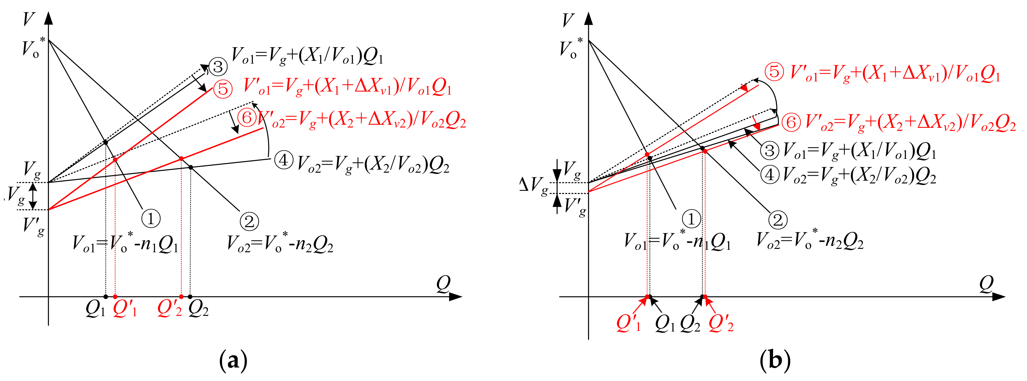
In the analyses, two cases are considered, i.e., case 1: (X1/X2) > 2 and case 2: (X1/X2) < 2. The reactive power regulating process are summarized in Figure 3, wherein lines ① and ② are the Q-V droop lines of DG inverters 1 and 2; lines ③ and ④ are the characteristics among output voltage Vo, PCC voltage Vg and reactive power Q of DG inverters 1 and 2 with conventional droop control (constant virtual inductance is added), whereas lines ⑤ and ⑥ are their characteristics with the proposed adaptive virtual inductance control. In addition, because the variations of output voltages of DG inverters are within a small allowable range (e.g., ±10%), it is reasonable to treat (Xi/Voi) as a constant in the analysis.
Case 1: (X1/X2) > 2. In this case, one can easily obtain that Vo1 > Vo2 and Q2 > 2Q1, which leads to considerable circulating current between two DG inverters, as seen in Figure 3a. However, according to (12), virtual inductances ΔXv1 and ΔXv2, which satisfy (ΔXv1 < 2ΔXv2), will be added to the line impedances. The outcome of this control is to make the line impedances closer to the relationship (X1 + ΔXv1) = 2(X2 + ΔXv2). As (11) is more likely to be satisfied, the circulating current can be greatly reduced. Finally, as the load reactive power remains unchanged, i.e., Q1 + Q2 = Q1 + Q2, after adding the virtual inductances, a further voltage drop ΔVg at the PCC generates, as shown in Figure 3a.
Case 2: (X1/X2) < 2. In this case, it is obtained that Vo1 < Vo2 and Q2 < 2Q1, as shown in Figure 3b. Obviously, circulating current exists in the system. However, thanks to the added virtual inductances, which satisfy (ΔXv1 > 2ΔXv2) according to (12), the line impedances are automatically adjusted in the direction of making (X1 + ΔXv1) and 2(X2 + ΔXv2) close to each other. Evidently, the circulating current is suppressed. Similarly, there is a voltage drop in the PCC voltage.
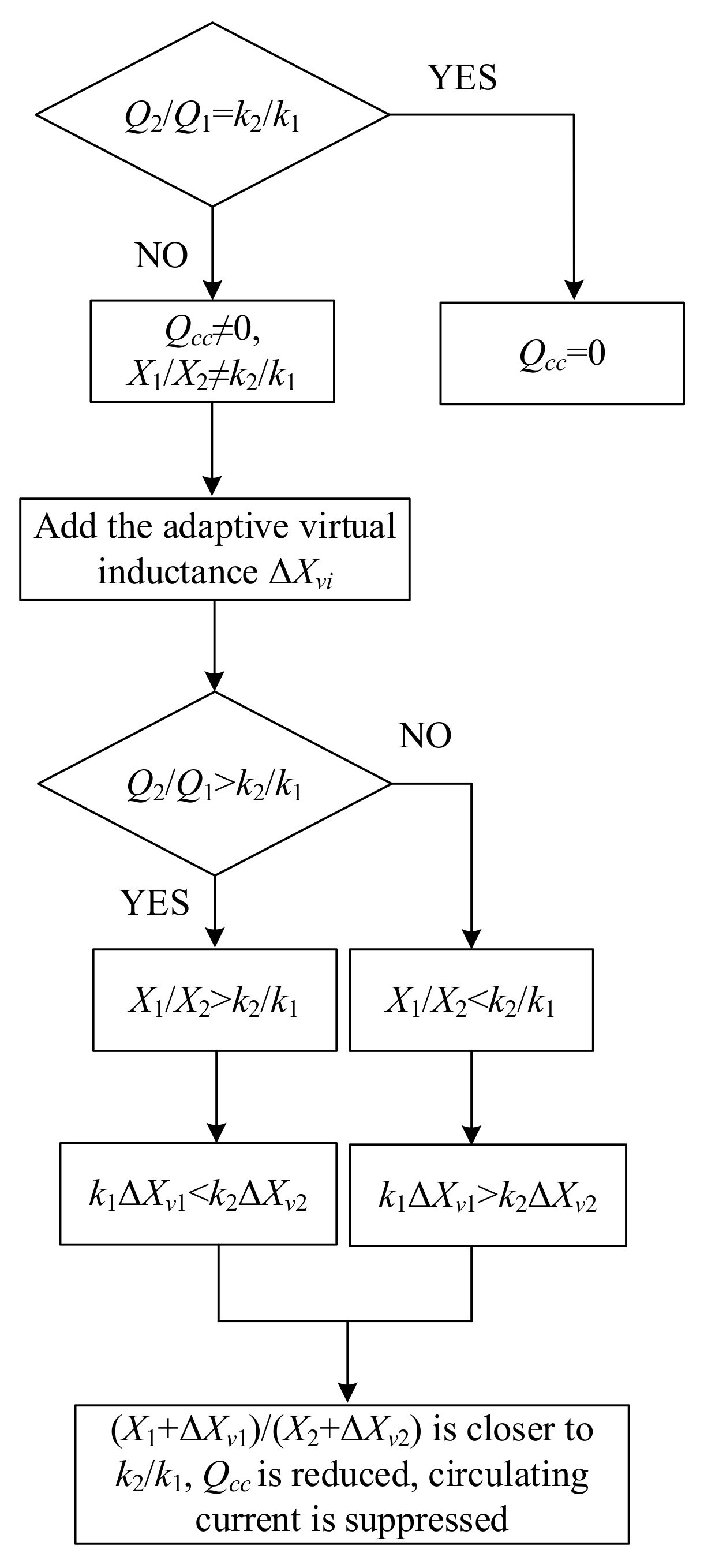
Hence, it can be concluded that the proposed method has strong ability in attenuating the circulating currents in paralleled inverters. Besides, as no common signals or communications are needed in the proposed control, it is a total discrete method, which makes the system feature high flexibility and scalability. Figure 4 depicts the working flow chart of the proposed control method.

3.2. Realization of the Adaptive Virtual Inductance

For each DG inverter, the commonly used cascaded control system, which is composed of an outer power droop control loop and inner voltage and current control loops (see Figure 1), is adopted. Because such a control system is well studied in the literature [9,10,11,12,13,14,15,16,17,18], its operational principle and design details are neglected. In this part, concentration is only focused on the method to add the optimized virtual inductance to each DG inverter determined by (12).
For one DG inverter, the voltage drop on the virtual inductance in the αβ frame is,
V V α i + j V V β i = j ω i L v t i ( i α i + j i β i ) = i β i ω i L v t i + j i α i ω i L v t i
where V and V are the α and β components of the voltage across virtual inductance respectively; iα and iβ are the α and β components of output current respectively; Lvt is the total added virtual inductance, which contains a constant part Lv and an adaptively changing part ΔLv.
After subtracting this voltage drop from the reference voltage, which is generated from the reactive power droop control loop, the final voltage reference for DG inverter is obtained. Afterwards, by controlling the output voltage of the DG inverter to follow this voltage reference, the addition of virtual inductance is achieved.
Consequently, one can use (12) to optimally tune the virtual inductance online and use (13) to add the tuned virtual inductance to the output of DG inverter through its own control system.

3.3. Stability Analysis

To better understand the stability feature of the DG inverter with the proposed adaptive virtual output inductance control method, small-signal stability analysis is made in this part [22]. To improve the accuracy of the analyzing result, the line impedance is considered. Furthermore, the line inductance is assumed to be part of the total virtual inductance Xvt to ease the analysis.
Based on the above assumption and according to (1) and (2), the small signal values of P and Q of the ith DG inverter at some steady state can be obtained as [23],
{ Δ P i = ω f i s + ω f i ( k P V i Δ V o i + k P δ i Δ δ i ) Δ Q i = ω f i s + ω f i ( k Q V i Δ V o i + k Q δ i Δ δ i )
where
{ k P V i = 1 R i 2 + X v t i 2 ( 2 R i V o i 0 R i V g 0 cos δ i 0 + X v t i V g 0 sin δ i 0 ) k P δ i = 1 R i 2 + X v t i 2 ( R i V o i 0 V g 0 sin δ i 0 + X v t i V o i 0 V g 0 cos δ i 0 ) k Q V i = 1 R i 2 + X v t i 2 ( 2 X v t i V o i 0 R i V g 0 sin δ i 0 X v t i V g 0 cos δ i 0 ) k Q δ i = 1 R i 2 + X v t i 2 ( X v t i V o i 0 V g 0 sin δ i 0 R i V o i 0 V g 0 cos δ i 0 )
In (14) and (15), symbol “Δ” and subscript “0” are used to represent the small signal value and steady-state value of the corresponding variable.
Then, based on the power droop control strategy shown in (4) and (5), it can be deduced that,
{ Δ ω i = m i Δ P i Δ V o i = n i Δ Q i
Substituting (15) into (16) and considering Δωi = sΔδi, we have,
Δ δ i s = m i ω f i s + ω f i ( k P V i Δ V o i + k P δ i Δ δ i )
Δ V o i = n i ω f i s + ω f i ( k Q V i Δ V o i + k Q δ i Δ δ i )
Substituting (18) into (17) yields,
s 3 + a s 2 + b s + c = 0
where
{ a = ω f i ( 2 + n i k Q V i ) b = ω f i ( m i k P δ i + n i k Q V i ω f i + ω f i ) c = m i ω f i 2 ( k P δ i + n i k P δ i k Q V i n i k P V i k Q δ i )
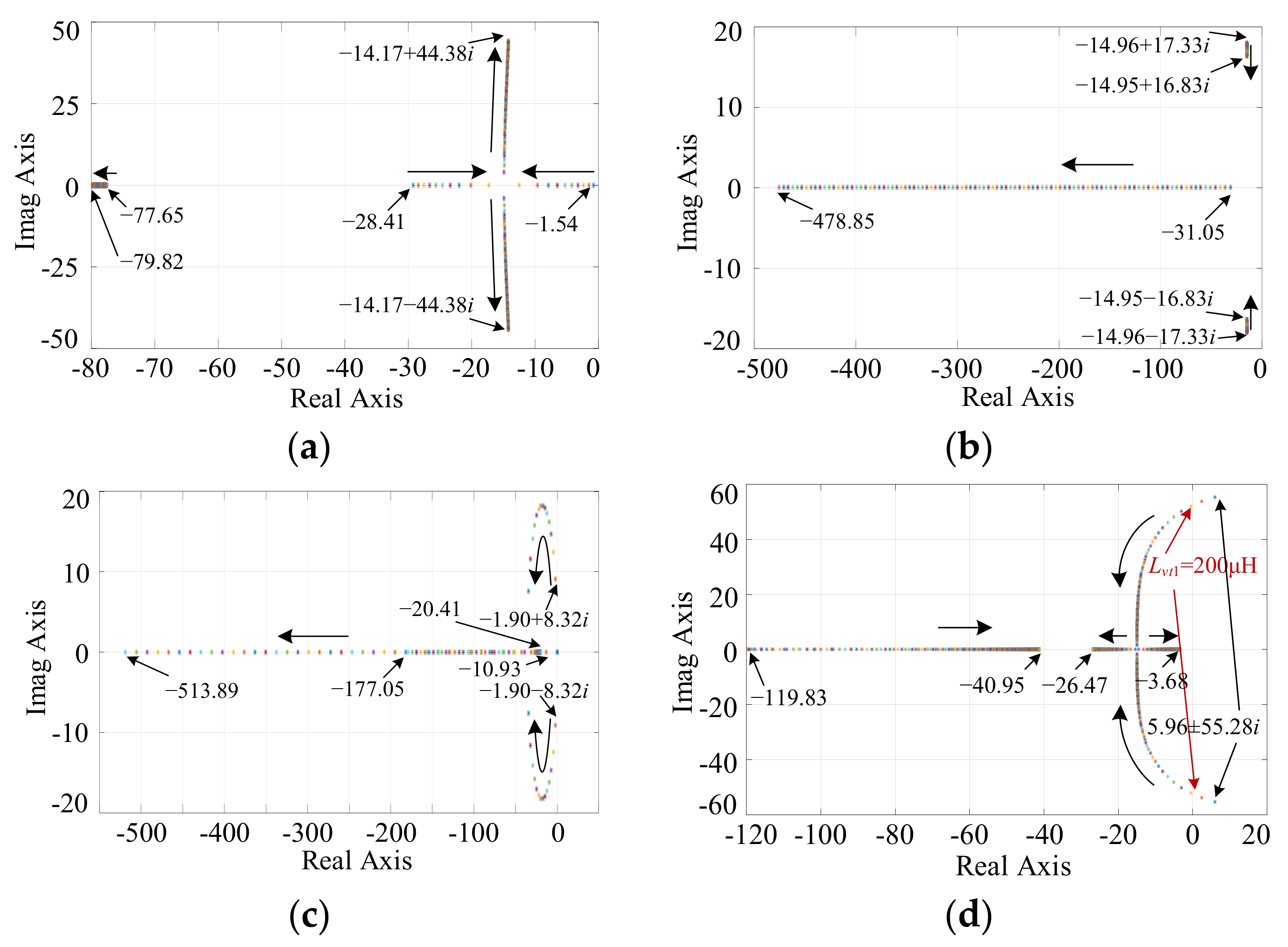
Hence, eigenvalues of the system can be obtained by using (19) and (20) at a certain steady state, which can then be used to judge the stability features of the DG inverter. For example, the root locus of DG inverter 1, whose parameters are listed in Table 1 in Section 4, is obtained in four cases:
Case 1:
n1 = 5 × 10⁻³ V/Var, Lvt1 = 2 mH, ωf1 = 30 rad/s, m1 is varying from 1 × 10⁻⁵ to 1 × 10⁻³ rad/(s·W);
Case 2:
m1 = 2.5 × 10⁻⁴ rad/(s·W), Lvt1 = 2 mH, ωf1 = 30, n1 is varying from 1 × 10⁻⁴ to 5 × 10⁻² V/Var;
Case 3:
m1 = 2.5 × 10⁻⁴ rad/(s·W), n1 = 5 × 10⁻³ V/Var, Lvt1 = 2 mH, ωf1 is varying from 0 to 150 rad/s;
Case 4:
m1 = 2.5 × 10⁻⁴ rad/(s·W), n1 = 5 × 10⁻³ V/Var, ωf1 = 30, Lvt1 is varying from 100 μH to 10 mH.
In the analyzing process, only resistive load is connected to the PCC (RL = 8 Ω on each phase). The analyzing results are shown in Figure 5a–d. It is easily known from Figure 5a–c that the increase of droop coefficients (m and n) and filter corner frequency ωf moves some eigenvalues away from the imaginary axis, which makes the system more stable. However, if the droop coefficients further increase, a pair of conjugate complex eigenvalues would move closer to the imaginary axis with increased imaginary values, which decreases the system’s damping eventually. Consequently, vibrations may be stimulated on some specific conditions, e.g., connection of constant power loads. Therefore, droop coefficients and filter corner frequency in the control system of the DG inverter have to be optimally selected.
As for the virtual inductance, it should be optimally designed as well. As can be shown in Figure 4d, if the virtual inductance is too small (<200 μH in this case), a pair of conjugate complex eigenvalues is located on the right half plane, which indicates that the system is unstable. Although the increase of virtual inductance may make the system stable by moving this pair of conjugate complex eigenvalues to the left, too large value would again moves one eigenvalue back towards the imaginary axis and deteriorates the stability of system. Hence, the design of the virtual inductance has to satisfy the stability criterion first, that is,
X v t i min 1 X v t i X v t i max 1
where Xvtimin1 and Xvtimax1 are the minimum and maximum value of the virtual inductance added to the ith DG inverter to ensure its stability.

3.4. Design of the Key Parameters

For the proposed method shown in (12), three parameters have to be well designed to ensure the good performance of the system, they are Qset, Xset and kv.
Firstly, Qset is selected to be the reactive power that the reference DG inverter can provide on condition that the whole microgrid needs its rated reactive power QN, that is,
Q s e t = k 1 k 1 + k 2 + + k n Q N
In the designing process, QN can also be chosen as the rated apparent power of the whole system for simplicity if the reactive power capacity is not given.
Then, parameters Xset and kv should be chosen in a way to ensure the stability of the microgrid and at the same time make sure the bus voltage is within the limit required by the electric standard for power grid. Because the actual line impedance (XL + R) is very small comparing to the added virtual reactance Xvt, it is neglected in the designing process.
For the virtual inductance, apart from satisfying the stability requirement determined by (21), it has to meet the requirements of achieving decoupled active and reactive power regulation and voltage limit as well, that is:
{ X v t i min 2 a R i X v t i max 2 ( X v t i max 2 ) 2 + V o i 2 P N i 0.436 X v t i max 0.48 V o i 2 P N i
where Xvtimin2 and Xvtimax2 are the minimum and maximum values of the virtual inductance added to the ith DG inverter to decouple its active and reactive power regulation and ensure the voltage drop is within the required limit, respectively; PN is the rated active power (per phase) of the ith DG inverter. To decouple the active and reactive power regulation, constant a in (23) is typically set within (5)–(10) to make the inductance dominate the line impedance. The voltage drop at PCC are limited to 10% of the output voltage, which then makes the ratio between the voltage drop on the virtual inductance and the output voltage of the DG inverter to be 0.436 in (23).
Consequently, it is also required that,
{ X v i + k 1 k i X s e t k 1 k i k v ( Q s e t k 1 k i Q i min ) X v t i min X v i + k 1 k i X s e t k 1 k i k v ( Q s e t k 1 k i Q i max ) X v t i max
where Xv is the initially added constant virtual inductance in the conventional droop control; Qmin is selected as 0; Qmax is the maximum reactive power of the DG inverter; Xvtimin and Xvtimax are the minimum and maximum total virtual inductance that is required by the ith DG inverter, which can be determined as,
{ X v t i min = max { X v t i min 1 , X v t i min 2 } X v t i max = min { X v t i max 1 , X v t i max 2 }
Thus, the selection of Xset and kv is hereby determined by considering (21)–(25).

4. Simulation and Experimental Verification

In this section, the proposed adaptive virtual inductance control method is firstly tested by simulations in Matlab/Simulink using a simulation model of an islanded microgrid composed by two DGs. The system structure and the detailed system parameters are given in Figure 1 and Table 1 respectively. As the initial constant virtual inductance of each DG inverter is set in a way to achieve decoupled regulation of its own active and reactive power, it is always the case that (11) is not satisfied.
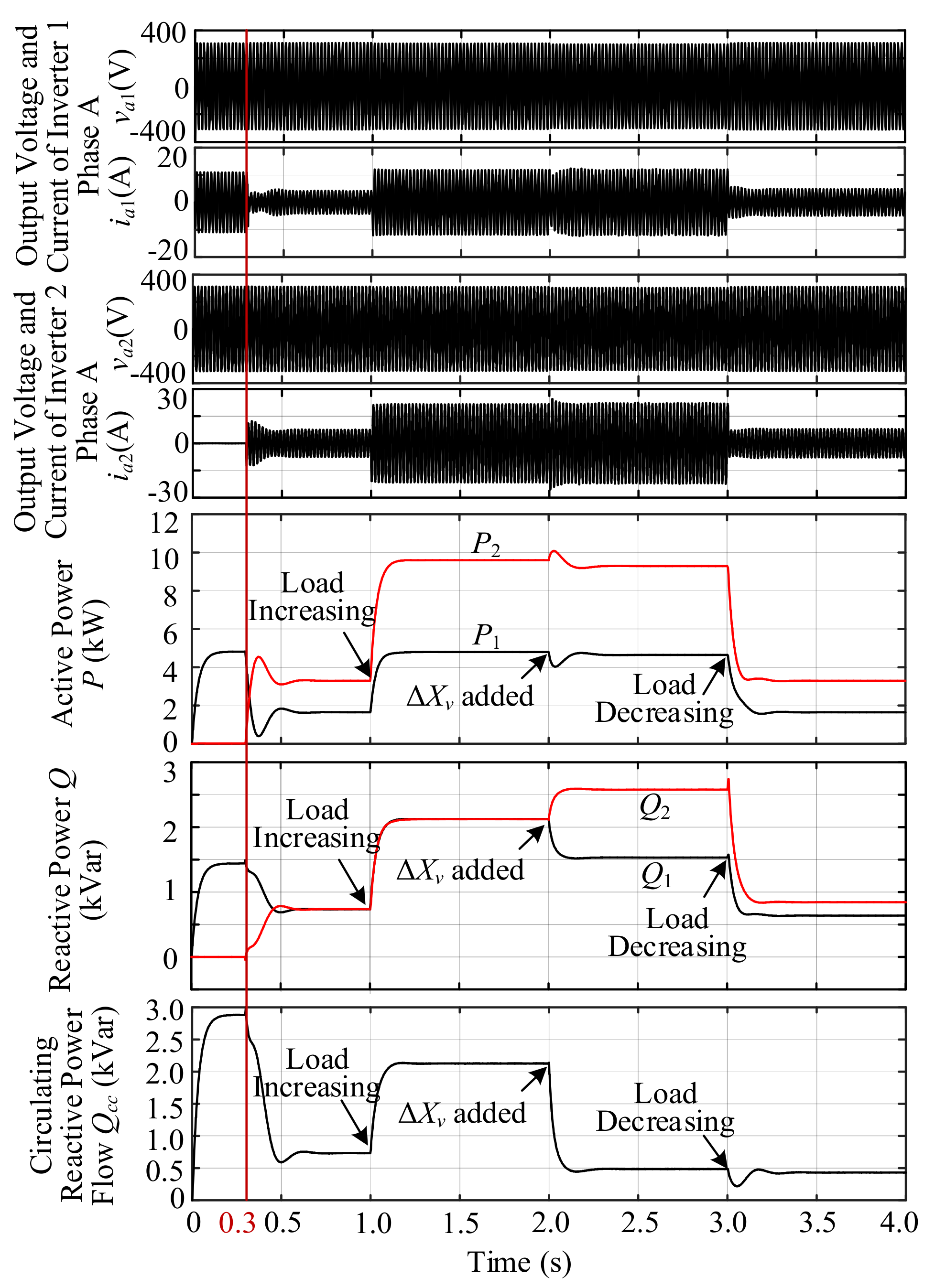
During the simulation, consecutive simulation events are applied to the considered system. Figure 6 gives out the simulation results. Firstly, in the time interval (0–0.3 s), a load with 5 kW active power and 1.5 kVar reactive power is connected to the system PCC. As can be seen in Figure 6, the load is only supplied by DG inverter 1. After pre-synchronization of voltage and frequency of the two DG inverters using phase-locked-loop (PLL) technique [24], DG inverter 2 is connected to the AC bus at time t = 0.3 s. While finding the fact that the active power P is accurately shared by the two DG inverters according to their own power ratings, i.e., P2 = 2P1, the reactive power Q is not shared unfortunately. The circulating reactive power flow Qcc (defined in (9)) is about 750 Var in the time interval (0.3 s–1 s). The same result happens in the time interval (1 s–2 s), where the load power has been stepped up to 15 kW and 4.5 kVar. Qcc increases to 2.1 kVar in this time interval. The simulation results evidently verify that the mismatch of line impedances would result in large circulating current. However, after the proposed virtual inductance control method is activated at t = 2 s, not only the active power is proportionally shared, but the circulating reactive power flow Qcc is reduced to less than 400 Var under both load conditions, which is a huge reduction especially in high reactive load power condition.
Then, experiments are done to verify the effectiveness of the proposed adaptive virtual inductance control. Figure 7 depicts a picture of the experimental platform established in the lab. The system parameters used in experiments are the same as those used in simulations, as shown in Table 1. Similar consecutive scenarios are applied to the considered experimental system in the order of pre-synchronization and connection of DG inverters at t = 0.3 s, increase of load power at t = 2 s, activation of proposed adaptive virtual inductance control at t = 3 s and decrease of load power at t = 4 s. The results are shown in Figure 8 and Figure 9. In Figure 8, C1, C2, C3 and C4 are the origins. The measuring units of voltage are 300 V/div, and the measuring unit of ia2 in Figure 8a is 30 A/div, while other measuring units of current in Figure 8 is 20 A/div. The measuring unit of active power in Figure 9 is 2.5 kW/div, and the measuring unit of reactive power in Figure 9 is 1 kVar/div. It can be seen from Figure 8 that with the cascade control system shown in Figure 1, the islanded microgrid has good static and dynamic performances. There are no large transients in the dynamic processes. Then in Figure 9, it can be clearly evidenced that in all events, the active power is accurately shared in proportional to their power ratings, i.e., P2 = 2P1, while the reactive power is not. Specifically, there are large circulating reactive power flow Qcc in the system before the proposed adaptive virtual inductance control method is activated at t = 3 s. The calculated Qcc are 600 Var and 1250 Var in the time intervals (1 s–2 s) and (2 s–3 s) respectively. However, thanks to the addition of the proposed adaptive virtual inductance, Qcc is able to be reduced to less than 150 Var under both load conditions, which can be easily noticed in Figure 9. Hence, the effectiveness and correctness of the proposed method has been verified.

5. Conclusions

In today’s microgrids, parallel operation of DG inverters is inevitable. However, due to the mismatch in line impedances of different DG inverters, there are always large circulating currents among DG inverters. This not only reduces the system efficiency, but also may limit the power supply abilities of some DG inverters.
In this paper, a decentralized circulating current suppression strategy, which is based on an adaptive virtual inductance control method, is proposed. According to the operational principle of the proposed control method, it is clearly seen that the value of the virtual inductance can be automatically adjusted with the change of the reactive power of each inverter. The operational principle, design of system parameters and implementation details are all elaborated. Compared with the existing solutions, the distinctive advantage of the proposed method is its high flexibility and scalability as it requires neither communications nor common signals. It is proved by simulations and experiments that the proposed method is correct and effective at the end of this paper.

Author Contributions

J.C. proposed the idea of this paper, did the theoretical analysis and wrote the paper; S.H. conceived, designed and performed the experiments; X.L. corrected and modified this paper.

Funding

This work is supported in part by Natural Science Foundation of Chongqing under Grant cstc2017jcyjAX0080 and in part by Fundamental Research Funds for Central Universities under Grant 2018CDQYZDH0039.

Acknowledgments

The authors would like to thank Jie Chen for the assistance with the experiments.

Conflicts of Interest

The authors declare no conflict of interest.

Nomenclature

DGsdistributed generators
PCCthe point of common coupling
LPFlow-pass filter
PLLphase-locked loop
Voi, V*o, Vgoutput voltage, nominal output voltage, voltage at PCC
δi, θipower angle, impedance angle
Pi, Qi, Qccoutput active power, output reactive power, circulating reactive power flow
ωi, ω*, ωfisystem frequency, nominal frequency, corner frequency of the LPF
mi, nidroop coefficients of active and reactive power
kicapacity ratio of each inverter
Xvi, XLiinitially added constant virtual output inductance, line inductance
Xi, ΔXviequivalent output inductance, adaptive virtual inductance
Xset, Qsetpre-set inductance and reactive power for the reference DG inverter
kvadaptive coefficient
V, Vthe α and β components of the voltage across virtual inductance
iα, iβthe α and β components of output current
QNthe rated power of the whole system
Xvtimin, Xvtimaxthe minimum and maximum total virtual inductance
aconstant within (5)–(10)

References

  1. Zhong, Q.C. Power-electronics-enabled autonomous power systems: Architecture and technical routes. IEEE Trans. Ind. Electron. 2017, 64, 5907–5918. [Google Scholar] [CrossRef]
  2. Xu, Q.; Hu, X.; Wang, P.; Xiao, J.; Tu, P.; Wen, C.; Lee, M.Y. A decentralized dynamic power sharing strategy for hybrid energy storage system in autonomous DC microgrid. IEEE Trans. Ind. Electron. 2017, 64, 5930–5941. [Google Scholar] [CrossRef]
  3. Bacha, S.; Picault, D.; Burger, B.; Otadui, I.E.; Martins, J. Photovoltaics in microgrids: An overview of grid integration and energy management aspects. IEEE Ind. Electron. Mag. 2015, 9, 33–46. [Google Scholar] [CrossRef]
  4. Mahmoud, M.S.; Rahman, M.S.U.; Sunni, F.M.A.L. Review of microgrid architectures—A system of systems perspective. IET Renew. Power Gen. 2015, 9, 1064–1078. [Google Scholar] [CrossRef]
  5. Wang, H.; Huang, J. Joint investment and operation of microgrid. IEEE Trans. Smart Grid 2017, 8, 833–845. [Google Scholar] [CrossRef]
  6. Xie, H.; Zheng, S.; Ni, M. Microgrid development in China: A method for renewable energy and energy storage capacity configuration in a megawatt-level isolated microgrid. IEEE Electrif. Mag. 2017, 5, 28–35. [Google Scholar] [CrossRef]
  7. Smith, M.; Ton, D. Key connections: The U.S. Department of Energy’s microgrid initiative. IEEE Power Energy Mag. 2013, 11, 22–27. [Google Scholar] [CrossRef]
  8. Di Fazio, A.R.; Russo, M.; Valeri, S.; de Santis, M. Sensitivity-Based Model of Low Voltage Distribution Systems with Distributed Energy Resources. Energies 2016, 9, 801. [Google Scholar] [CrossRef]
  9. Zhong, Q.C.; Zeng, Y. Universal droop control of inverters with different types of output impedance. IEEE Access 2016, 4, 702–712. [Google Scholar] [CrossRef]
  10. Sun, Y.; Hou, X.; Yang, J.; Han, H.; Su, M.; Guerrero, J.M. New perspectives on droop control in AC microgrids. IEEE. Trans. Ind. Electron. 2017, 64, 5741–5745. [Google Scholar] [CrossRef]
  11. Augustine, S.; Lakshminarasamma, N.; Mishra, M.K. Control of photovoltaic-based low-voltage dc microgrid system for power sharing with modified droop algorithm. IET Power Electron. 2016, 9, 1132–1143. [Google Scholar] [CrossRef]
  12. Marwali, M.; Jung, J.W.; Keyhani, A. Control of distributed generation systems-Part II: Load sharing control. IEEE Trans. Power Electron. 2004, 19, 1551–1561. [Google Scholar] [CrossRef]
  13. Li, Y.W.; Kao, C.N. An accurate power control strategy for power-electronics-interfaced distributed generation units operating in a low-voltage multibus microgrid. IEEE Trans. Power Electron. 2009, 24, 2977–2988. [Google Scholar]
  14. Zhong, Q.C. Robust droop controller for accurate proportional load sharing among inverters operated in parallel. IEEE Trans. Ind. Electron. 2013, 60, 1281–1290. [Google Scholar] [CrossRef]
  15. He, J.; Li, Y.W.; Blaabjerg, F. An Accurate Autonomous Islanding Microgrid Reactive Power, Imbalance Power and Harmonic Power Sharing Scheme. In Proceedings of the 2013 IEEE Energy Conversion Congress and Exposition, Denver, CO, USA, 15–19 September 2013; pp. 1337–1343. [Google Scholar]
  16. Mahmood, H.; Michaelson, D.; Jiang, J. Accurate reactive power sharing in an islanded microgrid using adaptive virtual impedances. IEEE Trans. Power Electron. 2015, 30, 1605–1617. [Google Scholar] [CrossRef]
  17. Fan, Y.; Hu, G.; Egerstedt, M. Distributed reactive power sharing control for microgrids with event-triggered communication. IEEE Trans. Control Syst. Technol. 2017, 25, 118–128. [Google Scholar] [CrossRef]
  18. Lee, C.T.; Chu, C.C.; Cheng, P.T. A new droop control method for autonomous operation of distributed energy resource interface converters. IEEE Trans. Power Electron. 2013, 28, 1980–1993. [Google Scholar] [CrossRef]
  19. Gu, H.; Wang, D.; Shen, H.; Zhao, W.; Guo, X. New power sharing control for inverter-dominated microgrid based on impedance match concept. Sci. World J. 2013, 2013, 816525. [Google Scholar] [CrossRef] [PubMed]
  20. Wang, X.; Blaabjerg, F.; Chen, Z. An Improved Design of Virtual Output Impedance Loop for Droop-Controlled Parallel Three-Phase Voltage Source Inverters. In Proceedings of the 2012 IEEE Energy Conversion Congress and Exposition (ECCE), Raleigh, NC, USA, 15–20 September 2012; pp. 2466–2473. [Google Scholar]
  21. Guerrero, J.M.; de Vicuña, L.G.; Matas, J.; Castilla, M.; Miret, J. Output impedance design of parallel-connected UPS inverters with wireless load-sharing control. IEEE Trans. Ind. Electron. 2005, 52, 1126–1135. [Google Scholar] [CrossRef]
  22. Di Fazio, A.R.; Russo, M.; Valeri, S.; de Santis, M. Linear method for steady-state analysis of radial distribution systems. Int. J. Electr. Power Energy Syst. 2018, 99, 744–755. [Google Scholar] [CrossRef]
  23. Guerrero, J.M.; de Vicuña, L.G.; Matas, J.; Castilla, M.; Miret, J. A Wireless Controller to Enhance Dynamic Performance of Parallel Inverters in Distributed Generation Systems. IEEE Trans. Power Electron. 2004, 19, 1205–1213. [Google Scholar] [CrossRef] [Green Version]
  24. Tran, T.V.; Chun, T.W.; Lee, H.H.; Kin, H.G.; Nho, E.C. PLL-based seamless transfer control between grid-connected and islanding modes in grid-connected inverters. IEEE Trans. Power Electron. 2014, 29, 5218–5228. [Google Scholar] [CrossRef]
Figure 1. Microgrid composed of two DG inverters connected in parallel (example system).
Energies 11 01725 g001
Figure 2. Equivalent circuit of two inverters operated in parallel (one phase).
Energies 11 01725 g002
Figure 3. Equivalent circuit of two inverters operated in parallel (one phase) Reactive power regulating process with proposed control method. (a) Case 1: (X1/X2) > 2; (b) Case 2: (X1/X2) < 2.
Energies 11 01725 g003
Figure 4. Working flow chart of adaptive virtual inductance control method when two inverters operated in parallel.
Energies 11 01725 g004
Figure 5. Root locus of DG inverter 1 under four cases. (a) Case 1; (b) Case 2; (c) Case 3; (d) Case 4.
Energies 11 01725 g005
Figure 6. Simulation results of the considered system.
Energies 11 01725 g006
Figure 7. Test-rig setup in the Lab.
Energies 11 01725 g007
Figure 8. Output voltages and currents of the two DG inverters (Phase A). (a) waveforms captured in the whole events; (b) zoomed in waveforms in TP1; (c) zoomed in waveforms in TP2.
Energies 11 01725 g008
Figure 9. Variations of active and reactive power of the paralleled DG inverters with and without the proposed adaptive virtual inductance control method.
Energies 11 01725 g009
Table 1. System Parameters Used in Simulations and Experiments.
System ParameterInverter 1Inverter 2
DC link voltage720 V DC720 V DC
Nominal AC bus voltage380 V380 V
Nominal frequency50 Hz50 Hz
Nominal output power5 kW, 1.5 kVar10 kW, 3 kVar
Filter inductance1 mH1.5 mH
Filter capacitance30 μF50 μF
Line impedance0.22 Ω, 100 μH0.235 Ω, 110 μH
Initial constant virtual inductance2.1 mH2.3 mH
P-ω droop coefficient2.5 × 10−4 rad/(s·W)1.25 × 10−4 rad/s·W
Q-V droop coefficient2 × 10−3 V/Var1 × 10−3 V/Var
Voltage regulatorkpvd1 = 0.1, kivd1 = 50
kpvq1 = 0.1, kivq1 = 50
kpvd2 = 0.15, kivd2 = 50
kpvq2 = 0.15, kivq2 = 50
Current regulatorkpid1 = 10, kiid1 = 1000
kpiq1 = 10, kiiq1 = 1000
kpid2 = 10, kiid2 = 1500
kpiq2 = 10, kiiq2 = 1500
Corner frequency of the LPF ωf30 rad/s30 rad/s
Set value of the adaptive virtual inductance Xset2 mH2 mH
Coefficient kv4 × 10−64 × 10−6
Set value of the reactive power Qset1.5 kVar1.5 kVar