Article

A New Single-Phase Transformerless Current Source Inverter for Leakage Current Reduction

Department of Electrical Engineering, Yanshan University, Qinhuangdao 066004, China
*
Author to whom correspondence should be addressed.
Energies 2018, 11(7), 1633; https://doi.org/10.3390/en11071633
Submission received: 1 June 2018 / Revised: 8 June 2018 / Accepted: 20 June 2018 / Published: 22 June 2018

Abstract

:
A new single-phase transformerless current source inverter is proposed in this paper. The proposed inverter can achieve leakage current reduction, which is crucial for the conventional current source inverter. The basic concept of the proposed solution is to develop the new inverter by the duality principle from the voltage source inverter. The theoretical analysis is carried out to determine the switching states of the proposed inverter for the leakage current reduction. Also, a new modulation strategy is presented to achieve the optimized switching states. Finally, the experimental results are presented. Comparing with conventional single-phase current source inverter, the leakage current can be significantly reduced by the proposed inverter, which verifies the effectiveness of the proposed solution.

1. Introduction

Power generation with solar energy is one of the most attractive solutions towards the utilization of renewable energy sources [1]. Typically, the inverter is used to interface the solar photovoltaic (PV) panel to the grid via a transformer. This kind of transformer is bulky, low-efficient and not cost-effective. This is the reason why transformerless PV inverters have been developed in recent years [2,3,4]. In practice, however, leakage current would arise due to a lack of galvanic isolation. The leakage current leads to the electromagnetic interference and potential safety issues [5,6]. Therefore, the VDE standard specifies that the leakage current should be less than 300 mA. Otherwise, the grid-connected inverter should be disconnected from the grid. Typically, the inverter is used to interface the PV panel and grid.
In order to solve the above mentioned problem, many solutions have been proposed in the last decades. To reduce the common-mode voltage (CMV), the novel modulation methods have been proposed [7,8,9,10,11,12,13,14]. An improved modulation with modified reference was proposed in [7]. Another modified modulation for reducing the CMV with specified vectors was proposed in [8]. Lian et al. reduce the CMV by introducing the average-value-reduction space vector modulation method. It applies the specified switching states with less CMV. Bradaschia et al. [15,16] proposed effective methods to reduce leakage current which only need additional fast-recovery diodes. To increase the optional switching states, the extra switch can also be added to the system. The principle of this method is to isolate the PV array and the grid during the zero switching states [17,18,19,20,21,22,23,24]. The methods may result in extra cost, losses, and increases control complexity. However, the electromagnetic interference (EMI) filter that is used to improve the output current quality could be removed from system if the leakage current is eliminated effectively. Thus, the cost of the EMI filter will be saved and the size of the inverter will be decreased. Miveh et al. [25,26,27] proposed four-wire inverters which only need extra neutral wire. For this reason, the direct current (DC)-link midpoint connects with the neutral point of the grid, and the voltages between the PV array and the ground are limited to a constant value. So, the leakage current can be reduced effectively. Some scholars proposed inverters which connect the PV array terminal with the grid terminal. The voltage between the PV array and the ground is clamped. Therefore, the leakage current can be reduced [28,29,30,31,32].
The two-stage power conversion would be complicated and have a low efficiency. An alternative solution is proposed using the current source inverter [33,34,35,36]. However, the leakage current could not be well suppressed with the conventional current source inverter, which is the motivation of the paper in solving this problem.
The objective of the paper is to present a new single-phase transformerless current source inverter with leakage current reduction. Like the VH6 inverter [3], the proposed inverter only needs a bidirectional switch which in serial with the alternating current (AC) side. When the inverter works in zero switching states, the extra switch will work to isolate the PV array and the grid. The rest paper is organized as follows. Section 2 provides the theoretical analysis as to why the conventional single-phase current source inverter fails to reduce the leakage current. The new solution for the leakage current reduction is presented in Section 3. The simulation and experimental results are provided in Section 4.

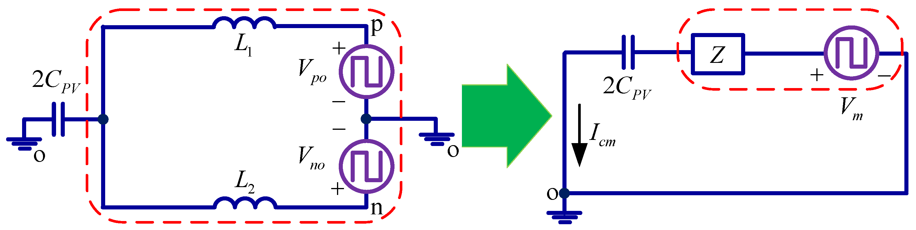
2. Conventional Current Source Inverter

The conventional single-phase current source inverter is illustrated in Figure 1, which consists of four switches in an H-bridge format. Therefore, it is called a CH4 inverter. In order to evaluate the leakage current reduction capability, the common-mode loop model is established, as shown in Figure 2.
In Figure 2, Vpo and Vno represent the voltage between the positive or negative rail and the ground, respectively. They can be regarded as the controllable voltage sources, which are regulated by the switching states si (i = 1, 2, 3, 4). Lf1, Lf2, L1, and Lf2 are the input and output inductors, respectively. IL is the output inductor current. Vg is the grid voltage. Ia and Ib can be regarded as the controllable current sources, which are determined by the switching states si (i = 1, 2, 3, 4).
Note that the leakage current is mainly determined by the common-mode behavior of the inverter. Therefore, the differential-model variables, e.g., Ia and Ib, are neglected for simplicity. In this way, the simplified common-mode loop model can be obtained, as shown in Figure 3.
In Figure 3, the equivalent impedance Z and equivalent voltage Vm can be expressed as follows, according to Thevenin’s theorem.
Z = L 1 L 2 s L 1 + L 2
V m = L 1 V n o + L 2 V p o L 1 + L 2 = V c m + ( L 2 L 1 ) ( V p o V n o ) 2 ( L 1 + L 2 )
In Equation (2), the Vcm represents the CMV.
V c m = ( V p o + V n o ) 2
The Vm would be equal to Vcm on the condition that L1 and L2 have the identical inductances, which are generally designed the same in practical applications.
The voltage Vpo and Vno can be derived as follows:
V p o = ( L f 1 s 1 L f 2 s 3 ) ( s 2 + s 4 ) s I L + s 1 ( s 2 + s 4 ) V g V n o = ( L f 1 s 2 L f 2 s 4 ) ( s 1 + s 3 ) s I L + s 2 ( s 1 + s 3 ) V g
where:
s i = { 1 0 , , when   ON   when   OFF ( i = 1 , 2 , 3 , 4 )
In the condition that L1 = L2 = L and Lf1 = Lf2 = Lf, Vm can be represented as follows:
V m = V c m = ( s 1 s 2 s 3 s 4 ) s L f I L + ( 2 s 1 s 2 + s 2 s 3 + s 1 s 4 ) V g 2
The leakage current Icm can be derived from Figure 3 as follows:
I c m = V m Z + 1 2 C P V s
Then, the common-mode current of Icm can be calculated by using Equations (6) and (7):
I c m = ( s 1 s 2 s 3 s 4 ) s L f I L + ( 2 s 1 s 2 + s 2 s 3 + s 1 s 4 ) V g 2 L s 2 + 1 2 C P V s
From Equation (8), it can be observed that Icm is dependent on many factors, such as the parasitic capacitance CPV, the grid voltage Vg, input filter inductance L, output filter inductance Lf, and switching states si. In practice, the switching states vary at a high frequency, which will have an impact on the CMV.
According to the Equation (6), the switching states and the corresponding CMV is analyzed as follows.
When the switches S1 and S4 are ON, the CMV can be obtained as Equation (9).
V c m = V g 2
When the switches S1 and S2 are ON, the CMV can be obtained. Considering the voltage drop across the inductor is much smaller than grid voltage, the CMV is approximately equal to the grid voltage as follows:
V c m = L f s I L + V g V g
When the switches S2 and S3 are ON, the CMV can be obtained as follows:
V c m = V g 2
When the switches S3 and S4 are ON, the CMV can be obtained. Note that the voltage drop across the inductor is much smaller than the grid voltage. Therefore, it can be neglected, and the CMV is approximately equal to zero as follows:
V c m = L f s I L 0
Based on the above analysis, the switching states and the corresponding voltage are listed in Table 1.
From Table 1, it can be observed that the CMV varies with the switching states in a high-frequency way. That is the reason why the conventional CH4 inverter fails to reduce the leakage current.

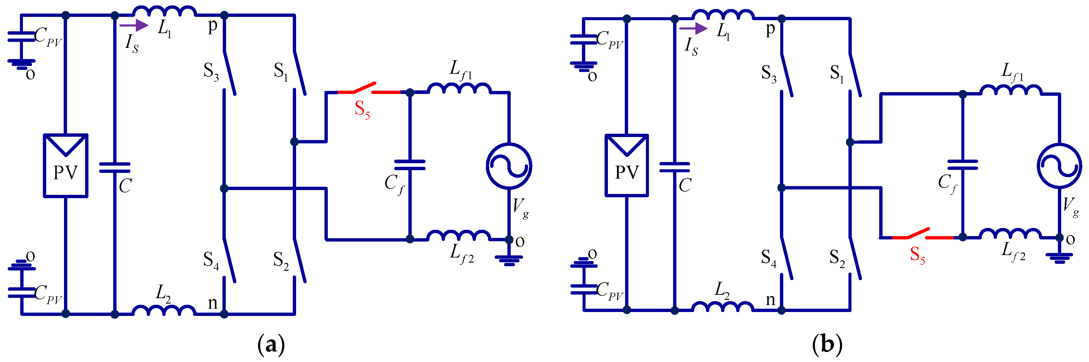
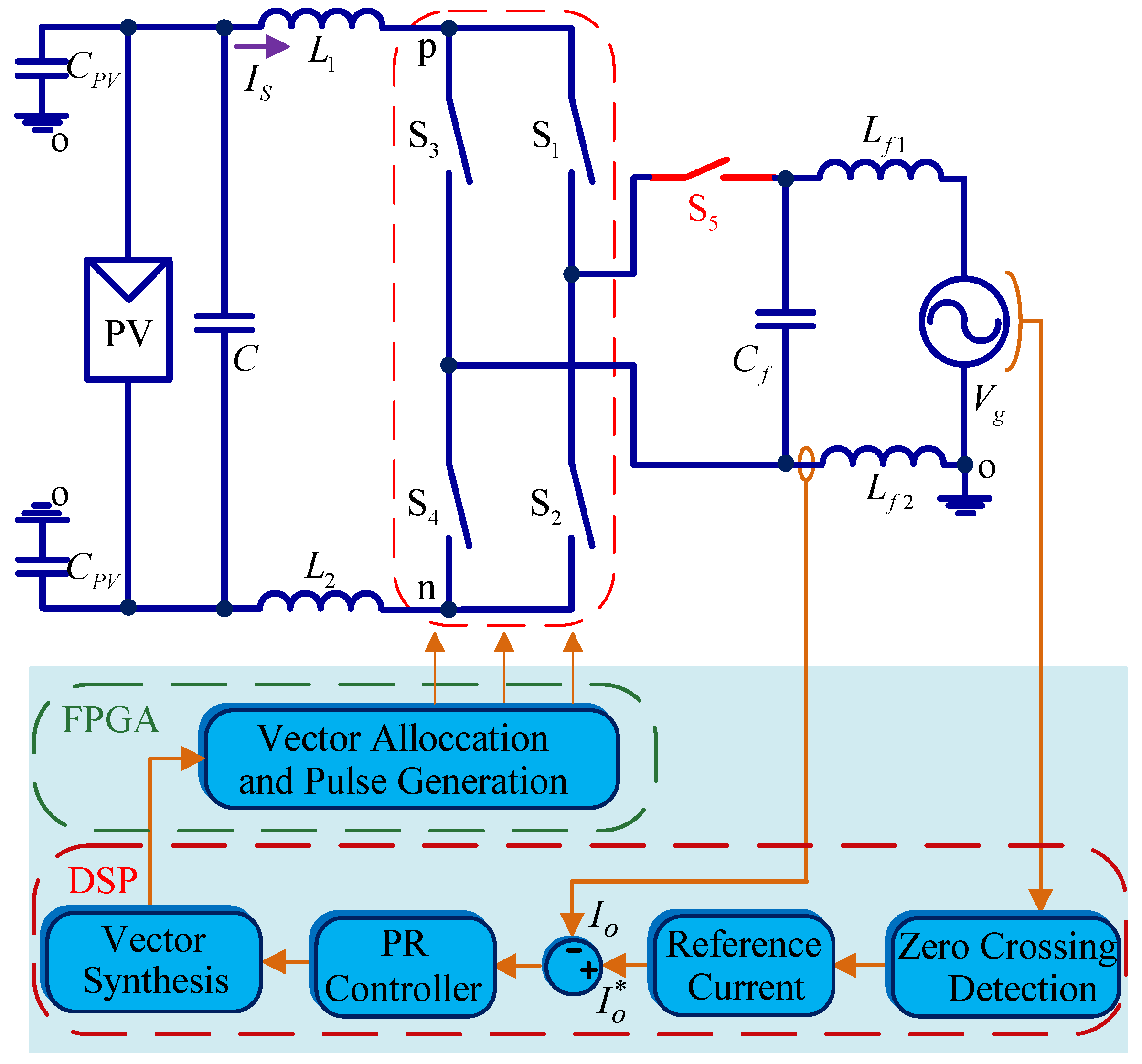
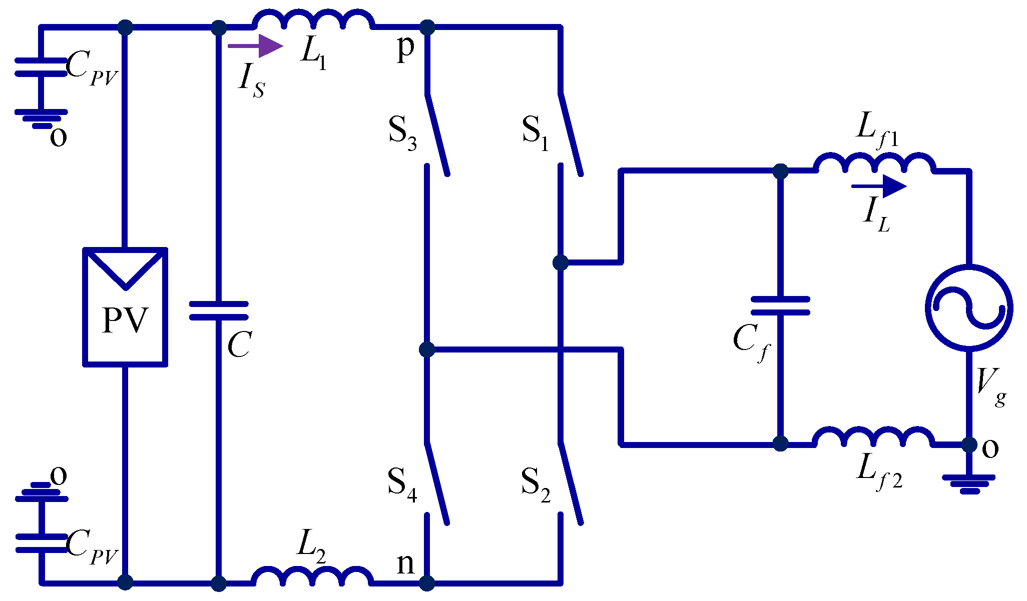
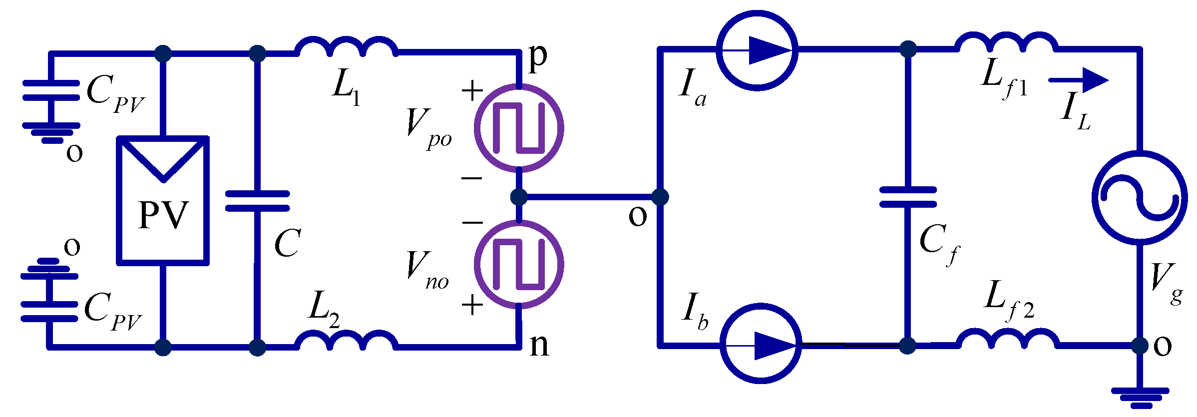
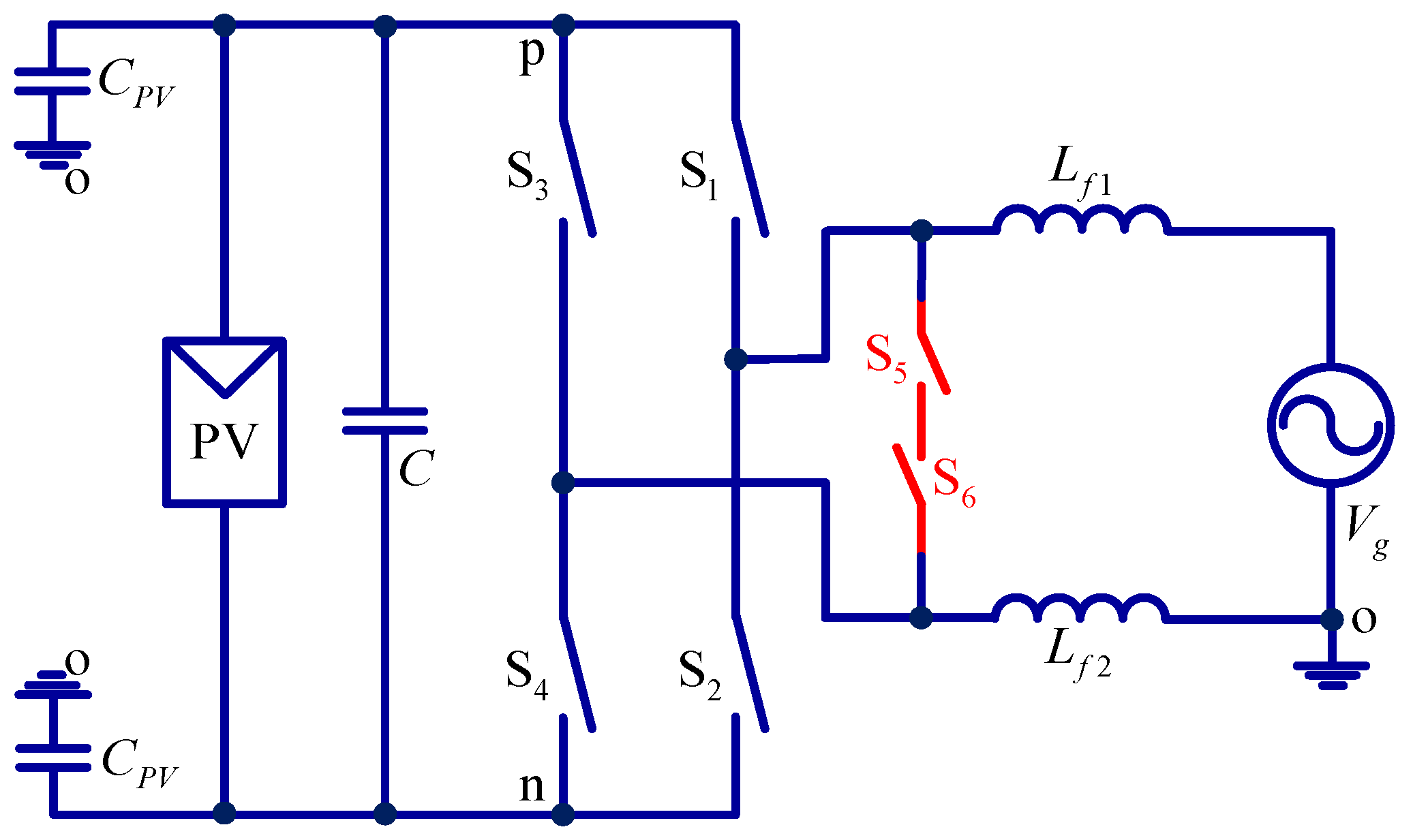
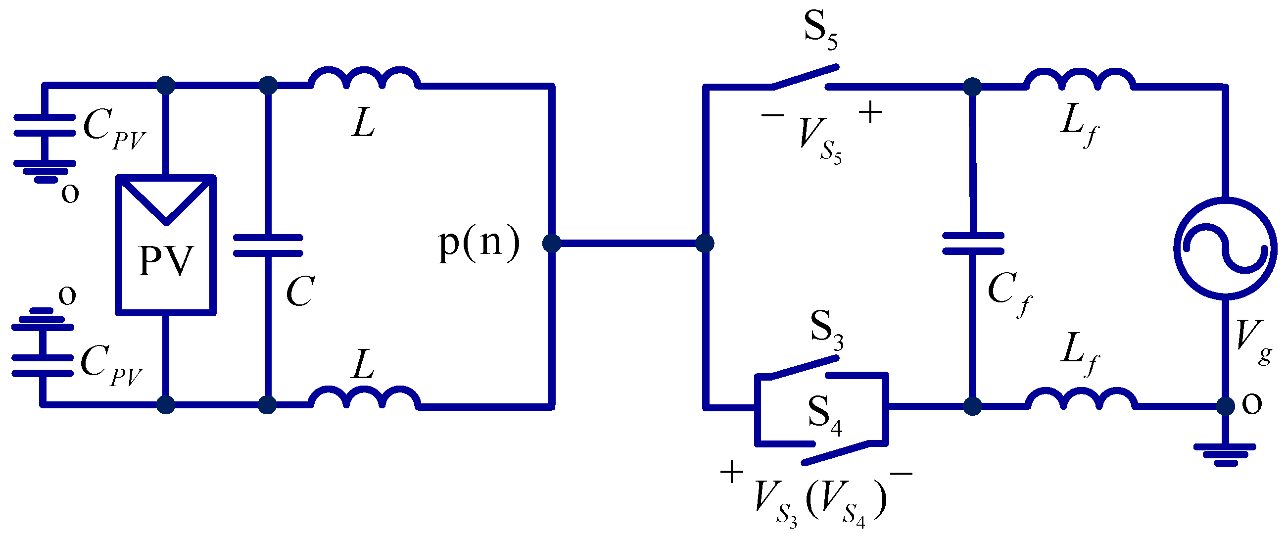
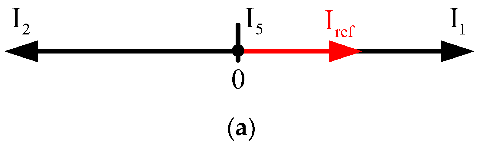
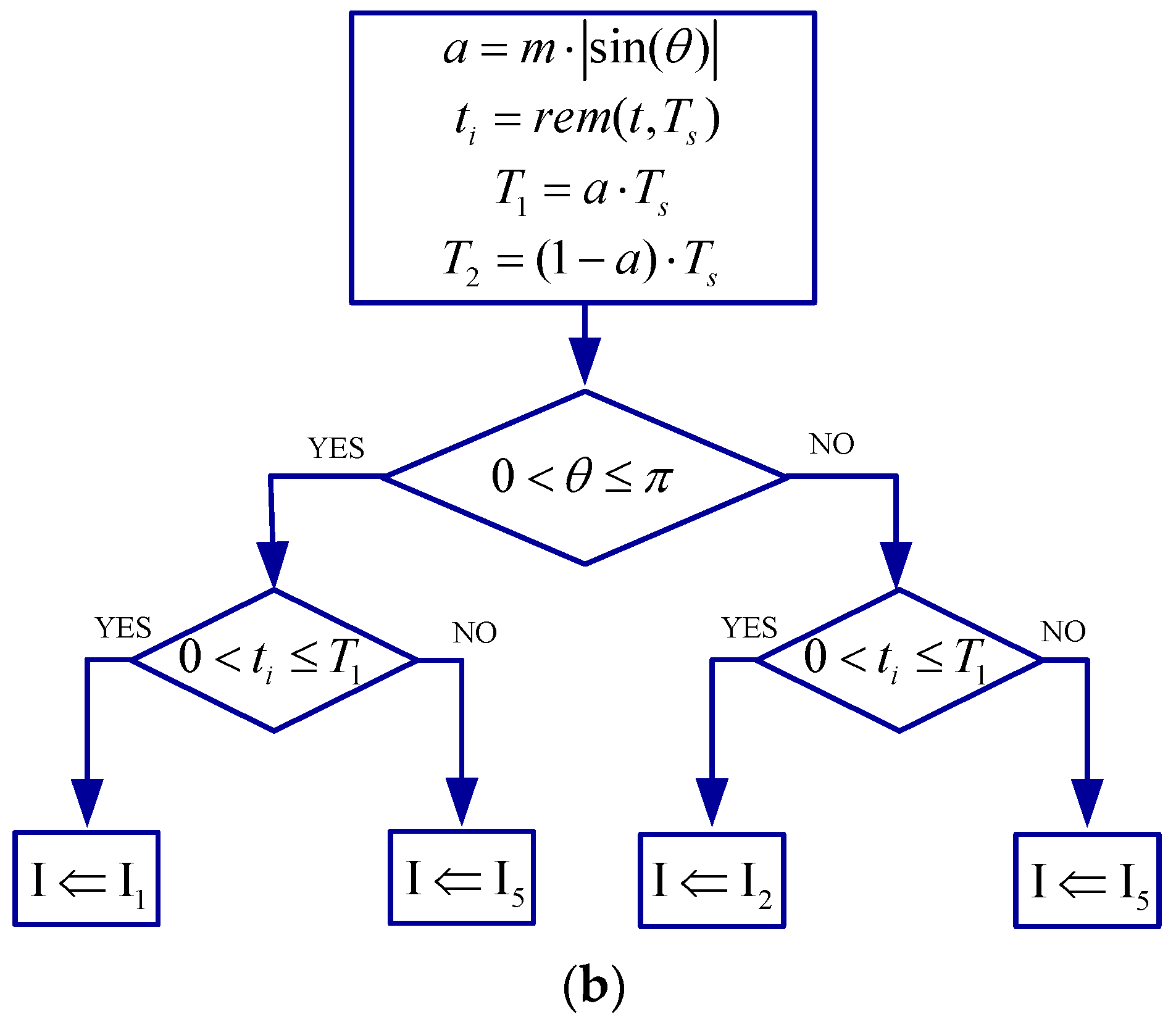
3. New Current Source Inverter

As discussed in the previous section, the leakage current is not able to be reduced by the conventional current source inverter. In order to solve the problem, a new current source inverter is proposed in this paper. The idea of the proposed solution is based on the duality principle. Inspired by the voltage source inverter named VH6 [3], the new current source inverter is proposed.
In Figure 4, the VH6 inverter has two switches in parallel with the AC side to improve the common-mode behavior, in order to reduce the leakage current. According to the duality principle, the proposed inverter has an additional switch that is in serial with the upper or lower side of the AC.
As shown in Figure 5, different from the VH6 inverter, the proposed inverter only needs one extra switch. Thus, it is called CH5 inverter.
In order to demonstrate the leakage current reduction capability of the proposed inverter, the operation principle and common-mode behavior are presented in this section. Note that the new inverter in Figure 5 is similar to the original, and thus only the inverter shown in Figure 5a is discussed for simplicity.
In the zero switching state, the new inverter would operate in the same way as the CH4 inverter, if the switch S5 is ON. However, when the switch S5 is OFF, the CH5 inverter would operate in a new mode, and the circuit model is shown in Figure 6. In this new mode, S1 and S2 are turned ON, and S3 and S4 are turned OFF.
As shown in Figure 6, the voltages Vpo and Vno would be the same, as shown in Equation (13). Also, the CMV is half of the grid voltage, as shown in Equation (14). So, this operation mode can be used as the zero switching state of the inverter to keep the CMV over half of the grid voltage.
V p o = V n o = V g 2
V c m = ( V p o + V n o ) 2 = V g 2
Based on the above analysis, the switching states and the corresponding voltage are listed in Table 2.
As shown in Table 2, it can be observed that the high-frequency CMV can be totally eliminated on the condition that the vectors of I1, I2, and I5 are applied, leaving only the low-frequency grid voltage. It should be noted that the leakage current is mainly determined by the high-frequency components of CMV, and the low-frequency component has a slim impact on the leakage current. Therefore, the vectors of I1, I2 and I5 are used for controlling the proposed inverter.
The control structure of the proposed inverter is shown in Figure 7.
As shown in Figure 7, the zero crossing detection is used for the grid synchronization to provide the reference angle for the grid current. The proportional resonant (PR) controller [37] is used to regulate the grid current with zero-steady state error. The gating signals are generated by the modulation strategy. And the detailed modulation procedure is presented, as shown in Figure 8.
In Figure 8a, during the positive half cycle, the reference vector Iref is synthesized by the active vector I1 and zero vector I5. While in the negative half cycle, the Iref is synthesized by active vector I2 and zero vector I5. The process of vector allocation is shown in Figure 8b. m represents the modulation index. t represents the operation time. Ts represents the switching period. T1 represents the dwell time of active vector. And T2 represents the dwell time of zero vector. a stands for the modulation signal which can be obtained from the output variable through the PR controller. As shown in Figure 8, the dwell time of vectors is allocated based on the modulation signal.
In the positive half cycle, the range of vector angle θ is from 0 to π. Iref can be represented as Equation (15).
I ref T s = T 1 I 1 + T 2 I 5
In the negative half cycle, the range of vector angle θ is from π to 2π. Iref can be represented as Equation (16).
I ref T s = T 1 I 2 + T 2 I 5

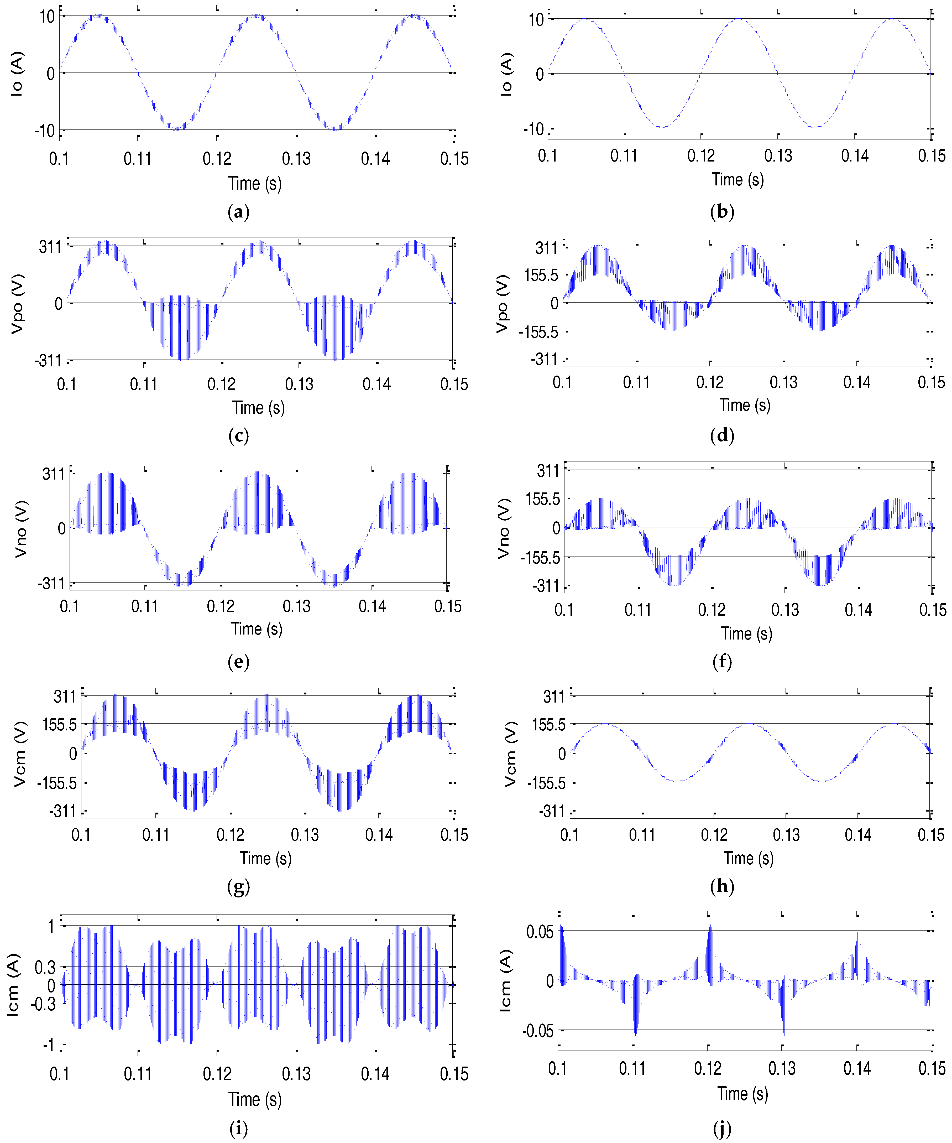
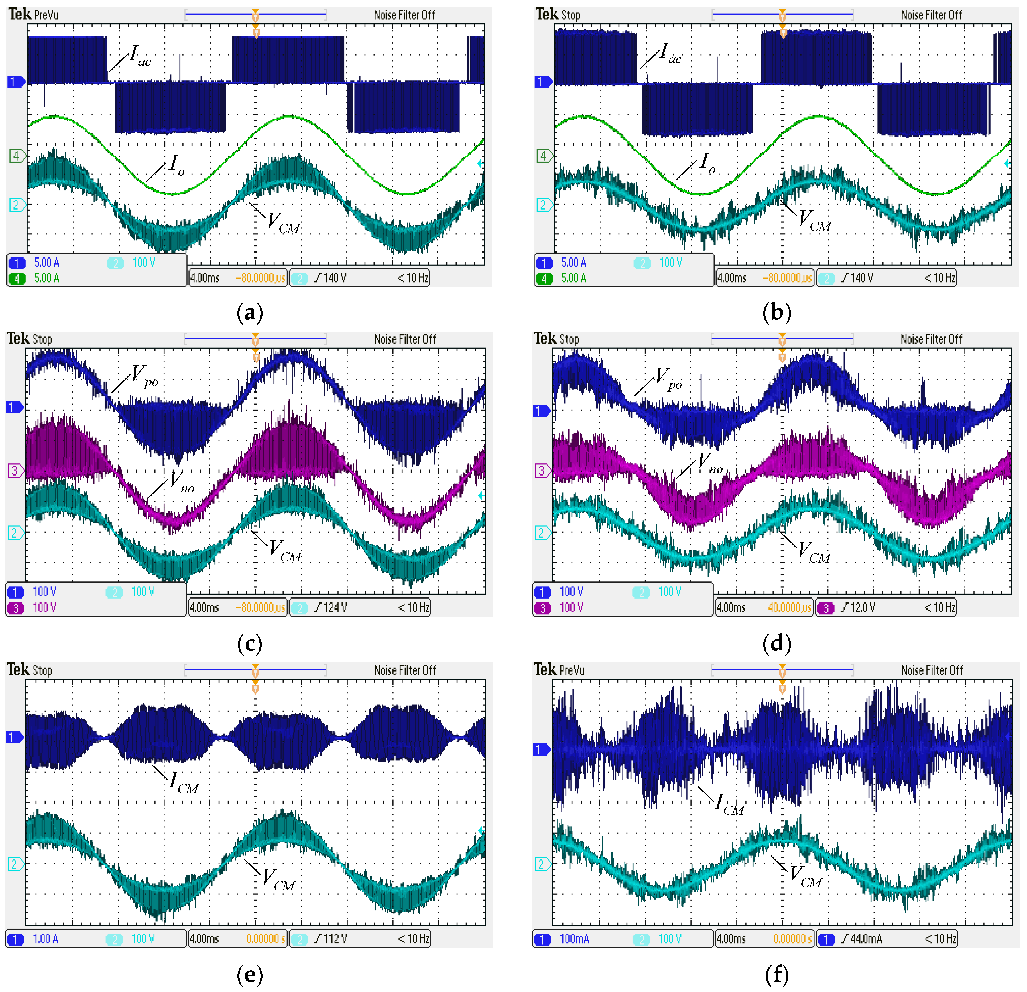
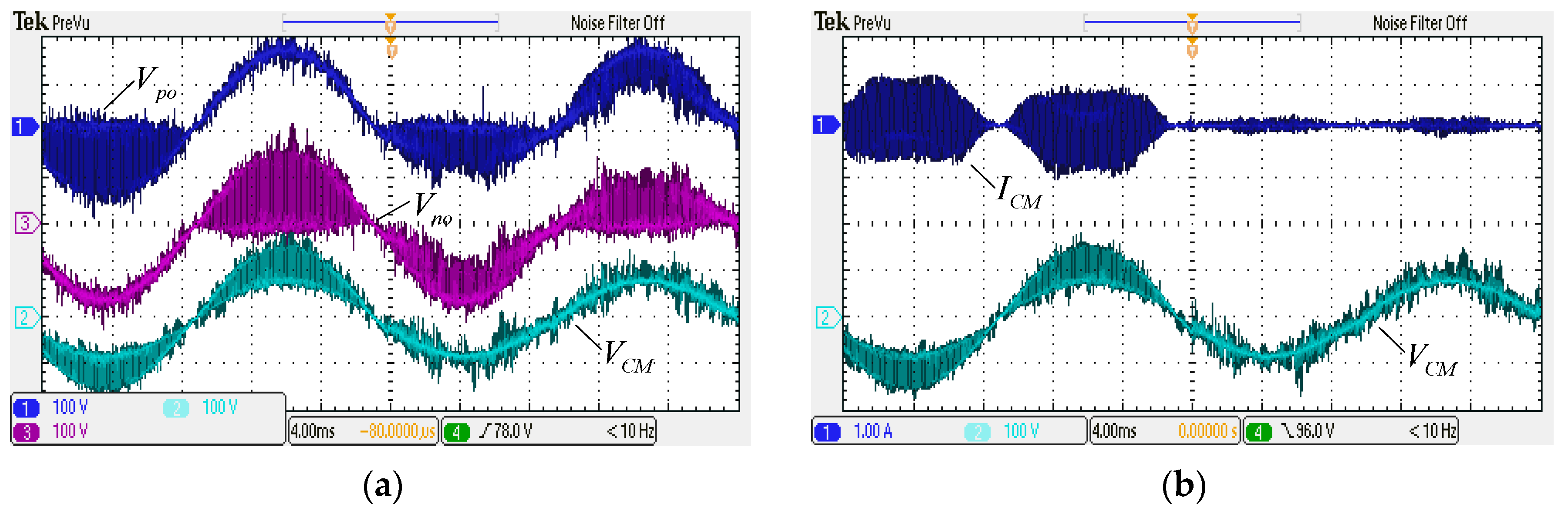
4. Simulation and Experimental Results

The simulation and experimental tests are carried out to verify the effectiveness of the proposed solution. In the simulation test, the grid voltage is 220 V/50 Hz. The input current source is 12.5 A. The filter inductance is 2.5 mH. The filter capacitance is 9.4 uF. The switching frequency is 10 kHz. The grid current is 10 A. And the parasitic capacitance is 75 nF.
Figure 9 shows the simulation results of the conventional CH4 inverter and proposed CH5 inverter. As shown in Figure 9a, influenced by the leakage current, the grid current is superposed with the high-frequency harmonics. The CMV of the CH4 is shown in Figure 9g; it is obvious that CMV consists of high-frequency components, which results in the undesirable leakage current, as shown in Figure 9i. The amplitude of the leakage current is far beyond 300 mA, which fails to comply with VDE-0126-1-1 standard. On the right, it is the waveforms of proposed inverter that correspond to the CH4. As shown in Figure 9b, the high frequency harmonics of the grid current is significantly reduced, compared with Figure 9a. The CMV is free of any high-frequency harmonics, and thus the leakage current is significantly reduced well below 300 mA, which meet the VDE-0126-1-1 standard.
In order to further verify the effectiveness of the proposed solution. The experimental prototype is established. The experimental parameters are listed as follows. The input current source is 8 A. The filter inductance is 2.5 mH. The filter capacitance is 9.4 uF. The switching frequency is 10 kHz. The grid current is 10 A. And the parasitic capacitance is 75 nF. The control and modulation algorithm are implemented in the DSP (TMS20F28335, Texas Instruments, Dallas, TX, USA) plus FPGA (XC6SLX9 2TQG144, Xilinx, San Jose, CA, USA) digital control platform
Figure 10 shows the experimental results of CH4 inverter and proposed CH5 inverter. It can be observed that the output currents are unipolar and sinusoidal before and after the filter as shown in Figure 10a. On the other hand, the CMV is time-varying with high-frequency components as shown in Figure 10c. Consequently, the leakage current of CH4 inverter is as high as 1.2 A, which fails to comply with the VDE-0126-1-1 standard, as shown in Figure 10e. On the right, it is the experimental waveforms of proposed inverter that correspond to the CH4. It can be observed that the high-frequency components of CMV are significantly suppressed, compared with the experimental results of the CH4 inverter. Consequently, the leakage current of the proposed CH5 inverter is much smaller than that of CH4 inverter. The amplitude of the leakage current is well below 300 mA, which meets the VDE-0126-1-1 standard.
The further dynamic experimental tests are carried out as shown in Figure 11. From 0 to 20 ms, S5 is kept on. It operates as the CH4 inverter. From 20 to 40 ms, S5 is active with the proposed modulation. It operates as the CH5 inverter. The dynamic experimental results show that the leakage current with the CH5 inverter is much lower than that with the CH4 inverter, which again verifies the effectiveness of the proposed solution.

5. Conclusions

This paper has presented a new single-phase transformer-less current source inverter. It can achieve the leakage current reduction which is crucial for the PV inverter. The new current source inverter with the improved common mode behavior is established by the duality principle. The proposed solution only needs one extra switch to break the common-mode loop of the system for the leakage current reduction. Aside from that, a new one-dimensional space vector modulation is presented for eliminating the high-frequency common-mode voltage, so as to reduce the leakage current. The experimental results reveal that the leakage current can be significantly reduced from 1.2 to 0.19 A with the proposed solution. Therefore, it is an attractive solution for the single-phase transformerless PV systems. It should be noted that IGBT is used for the proposed inverter. There is a limitation regarding the switching frequency. With the rapid development of the wide-bandgap semiconductors such as the commercially available silicon carbide and GaN power device, the switching frequency would be high for a better techno-industrial level, which is the subject of our future research.

Author Contributions

X.G. and J.Z. (Jianhua Zhang) designed the main parts of the study. J.Z. (Jiale Zhou) and B.W. helped in the fabrication.

Funding

This research was supported by the National Natural Science Foundation of China (Grant: 51777181), Hundred Excellent Innovation Talents Support Program of Hebei Province (SLRC2017059), and Science Foundation for Returned Scholars of Hebei Province (CL201622).

Acknowledgments

The author would like to thank Yanshan University for supporting this research.

Conflicts of Interest

The authors declare no conflict of interest.

References

  1. Su, M.; Luo, C.; Hou, X.; Yuan, W.; Liu, Z.; Han, H.; Guerrero, J.M. A Communication-Free Decentralized Control for Grid-Connected Cascaded PV Inverters. Energies 2018, 11, 1375. [Google Scholar] [CrossRef]
  2. Xiao, H.; Zhang, L.; Li, Y. An improved zero-current-switching single-phase transformerless PV H6 inverter with switching loss-free. IEEE Trans. Ind. Electron. 2017, 64, 7896–7905. [Google Scholar] [CrossRef]
  3. Li, W.; Gu, Y.; Luo, H.; Cui, W.; He, X.; Xia, C. Topology review and derivation methodology of single-phase transformerless photovoltaic inverters for leakage current suppression. IEEE Trans. Ind. Electron. 2015, 62, 4537–4551. [Google Scholar] [CrossRef]
  4. Guo, X.Q.; Yang, Y.; Zhu, T.Y. ESI: A novel three-phase inverter with leakage current attenuation for transformerless PV systems. IEEE Trans. Ind. Electron. 2018, 65, 2967–2974. [Google Scholar] [CrossRef]
  5. Liu, C.; Wang, Y.; Cui, J.; Zhi, Y.; Liu, M.; Cai, G. Transformerless photovoltaic inverter based on interleaving high-frequency legs having bidirectional capability. IEEE Trans. Power Electron. 2016, 31, 1131–1142. [Google Scholar] [CrossRef]
  6. Guo, X.Q.; Jia, X. Hardware-based cascaded topology and modulation strategy with leakage current reduction for transformerless PV systems. IEEE Trans. Ind. Electron. 2016, 62, 7823–7832. [Google Scholar] [CrossRef]
  7. Sonti, V.; Jain, S.; Bhattacharya, S. Analysis of the modulation strategy for the minimization of the leakage current in the PV grid-connected cascaded multilevel inverter. IEEE Trans. Power Electron. 2017, 32, 1156–1169. [Google Scholar] [CrossRef]
  8. Lee, J.S.; Lee, K.B. New modulation techniques for a leakage current reduction and a neutral-point voltage balance in transformerless photovoltaic systems using a three-level inverter. IEEE Trans. Power Electron. 2014, 29, 1720–1732. [Google Scholar] [CrossRef]
  9. Guo, X.Q.; Wei, B.; Zhu, T.Y.; Lu, Z.; Tan, L.; Sun, X.; Zhang, C. Leakage current suppression of three-phase flying capacitor PV inverter with new carrier modulation and logic function. IEEE Trans. Power Electron. 2018, 33, 2127–2135. [Google Scholar] [CrossRef]
  10. Lian, Y.; Li, Y.W.; Quan, Z.; Zargari, N.R.; Cheng, Z. SVM strategies for common-mode current reduction in transformerless current-source drives at low modulation index. IEEE Trans. Power Electron. 2017, 32, 1312–1323. [Google Scholar] [CrossRef]
  11. Lian, Y.; Zhang, Y.; Li, Y.W.; Zargari, N.R.; Cheng, Z. Common-mode resonance suppression in transformerless PWM current-source drive. IEEE Trans. Power Electron. 2016, 31, 5721–5731. [Google Scholar] [CrossRef]
  12. Siwakoti, Y.P.; Town, G.E. Three-phase transformerless grid connected Quasi Z-Source Inverter for solar photovoltaic systems with minimal leakage current. In Proceedings of the 2012 3rd IEEE International Symposium on Power Electronics for Distributed Generation Systems (PEDG), Aalborg, Denmark, 25–28 June 2012; pp. 368–373. [Google Scholar]
  13. Bradaschia, F.; Cavalcanti, M.C.; Ferraz, P.E.P.; Dos Santos, E.C., Jr.; Neves, F.A.S. Eliminating leakage currents in transformerless Z-source inverters for photovoltaic systems. In Proceedings of the 20th IEEE International Symposium on Industrial Electronics (ISIE), Gdansk, Poland, 27–30 June 2011. [Google Scholar]
  14. Bradaschia, F.; Cavalcanti, M.C.; Ferraz, P.E.P.; Azevedo, G.M.S.; Neves, F.A.S.; Dos Santos, E.C., Jr. Stability analysis of reduced leakage current modulation techniques for Z-source inverters in transformerless photovoltaic applications. In Proceedings of the IEEE Energy Conversion Congress and Exposition (ECCE), Phoenix, AZ, USA, 17–22 September 2011. [Google Scholar]
  15. Bradaschia, F.; Cavalcanti, M.C.; Ferraz, P.E.P.; Neves, F.A.S.; Dos Santos, E.C., Jr.; Da Silva, J.H.G.M. Modulation for three-phase transformerless z-source inverter to reduce leakage currents in photovoltaic systems. IEEE Trans. Power Electron. 2011, 58, 5385–5395. [Google Scholar] [CrossRef]
  16. Ferraz, P.E.P.; Bradaschia, F.; Cavalcanti, M.C.; Neves, F.A.S.; Azevedo, G.M.S. A modified Z-source inverter topology for stable operation of transformerless photovoltaic systems with reduced leakage currents. In Proceedings of the 11th Brazilian Power Electronics Conference (COBEP), Natal, Brazil, 11–25 September 2011. [Google Scholar]
  17. Zhou, Y.; Li, H. Analysis and suppression of leakage current in cascaded-multilevel-inverter-based PV systems. IEEE Trans. Power Electron. 2014, 29, 5265–5277. [Google Scholar] [CrossRef]
  18. Zhang, L.; Sun, K.; Xing, Y.; Xing, M. H6 transformerless full-bridge PV grid-tied inverters. IEEE Trans. Power Electron. 2014, 29, 1229–1238. [Google Scholar] [CrossRef]
  19. Xiao, H.F.; Liu, X.P.; Lan, K. Zero-voltage-transition full bridge topologies for transformerless photovoltaic grid-connected inverter. IEEE Trans. Ind. Electron. 2014, 61, 5393–5401. [Google Scholar] [CrossRef]
  20. Guo, X.Q. A novel CH5 inverter for single-phase transformerless photovoltaic system applications. IEEE Trans. Circuits Syst. 2017, 64, 1197–1201. [Google Scholar] [CrossRef]
  21. Concari, L.; Barater, D.; Buticchi, G.; Concari, C.; Liserre, M. H8 inverter for common-mode voltage reduction in electric drives. IEEE Trans. Ind. Appl. 2016, 52, 4010–4019. [Google Scholar] [CrossRef]
  22. Guo, X.Q.; Zhou, J.L.; He, R.; Jia, X.Y.; Rojas, C.A. Leakage current attenuation of a three-phase cascaded inverter for transformerless grid-connected PV systems. IEEE Trans. Ind. Electron. 2018, 65, 676–686. [Google Scholar] [CrossRef]
  23. Li, K.; Shen, Y.; Yang, Y.; Qin, Z.; Blaabjerg, F. A transformerless single-phase symmetrical Z-source HERIC inverter with reduced leakage currents for PV systems. In Proceedings of the 2018 IEEE Applied Power Electronics Conference and Exposition (APEC), San Antonio, TX, USA, 4–8 March 2018; pp. 356–361. [Google Scholar]
  24. Guo, X. Three phase CH7 inverter with a new space vector modulation to reduce leakage current for transformerless photovoltaic systems. IEEE Emerg. Sel. Top. Power Electron. 2017, 5, 708–712. [Google Scholar] [CrossRef]
  25. Miveh, M.R.; Rahmat, M.F.; Ghadimi, A.A.; Mustafa, M.W. Control techniques for three-phase four-leg voltage source inverters in autonomous microgrids: A review. Renew. Sustain. Energy Rev. 2016, 54, 1592–1610. [Google Scholar] [CrossRef]
  26. Lo, Y.K.; Chen, C.L. Three-phase four wire voltage controlled AC line conditioner with unity input power factor and minimized output voltage harmonics. Proc. Inst. Electr. Eng. 1995, 142, 43–49. [Google Scholar]
  27. Sun, Y.; Liu, Y.L.; Su, M.; Han, H.; Li, X. Topology and control of a split-capacitor four-wire current source inverter with leakage current suppression capability. IEEE Trans. Power Electron. 2018. [CrossRef]
  28. Kadam, A.; Shukla, A. A multilevel transformerless inverter employing ground connection between PV negative terminal and grid neutral point. IEEE Trans. Ind. Electron. 2017, 64, 8897–8907. [Google Scholar] [CrossRef]
  29. Siwakoti, Y.; Blaabjerg, F. Common-ground-type transformerless inverters for single-phase solar photovoltaic systems. IEEE Trans. Ind. Electron. 2018, 65, 2100–2111. [Google Scholar] [CrossRef]
  30. Xia, Y.; Roy, J.; Ayyanar, R. A capacitance-minimized, doubly grounded transformer less photovoltaic inverter with inherent active-power decoupling. IEEE Trans. Power Electron. 2017, 32, 5188–5201. [Google Scholar] [CrossRef]
  31. Rajeev, M.; Agarwal, V. Single phase current source inverter with multiloop control for transformerless grid-PV interface. IEEE Trans. Ind. Appl. 2018, 54, 2416–2424. [Google Scholar] [CrossRef]
  32. Saeidabadi, S.; Ashraf Gandomi, A.; Hosseini, S.H. A novel transformerless photovoltaic grid-connected current source inverter with ground leakage current elimination. In Proceedings of the 2017 8th Power Electronics, Drive Systems & Technologies Conference (PEDSTC), Mashhad, Iran, 14–16 February 2017; pp. 61–66. [Google Scholar]
  33. Guo, X.; Yang, Y.; Zhang, X. Advanced control of grid-connected current source converter under unbalanced grid voltage conditions. IEEE Trans. Ind. Electron. 2018. [Google Scholar] [CrossRef]
  34. Guo, X.; Yang, Y.; Wang, X. Optimal space vector modulation of current source converter for dc-link current ripple reduction. IEEE Trans. Ind. Electron. 2018. [Google Scholar] [CrossRef]
  35. Guo, X.; Xu, D.; Guerrero, J.M.; Wu, B. Space vector modulation for dc-link current ripple reduction in back-to-back current-source converters for microgrid applications. IEEE Trans. Ind. Electron. 2015, 62, 6008–6013. [Google Scholar] [CrossRef]
  36. Lebre, J.R.; Portugal, P.M.M.; Watanabe, E.H. Hybrid HVDC (H2VDC) System Using Current and Voltage Source Converters. Energies 2018, 11, 1323. [Google Scholar] [CrossRef]
  37. Guo, X.Q.; Liu, W.; Lu, Z. Flexible power regulation and current-limited control of grid-connected inverter under unbalanced grid voltage faults. IEEE Trans. Ind. Electron. 2017, 64, 7425–7432. [Google Scholar] [CrossRef]
Figure 1. The CH4 inverter.
Energies 11 01633 g001
Figure 2. Circuit model of the CH4 inverter.
Energies 11 01633 g002
Figure 3. Simplified common-mode model of the CH4 inverter.
Energies 11 01633 g003
Figure 4. The VH6 inverter.
Energies 11 01633 g004
Figure 5. The proposed inverter.
Energies 11 01633 g005
Figure 6. Circuit model of CH5 in new mode.
Energies 11 01633 g006
Figure 7. Control structure of the proposed inverter.
Energies 11 01633 g007
Figure 8. The schematic diagram. (a) The vector synthesis; (b) The vector allocation.
Energies 11 01633 g008aEnergies 11 01633 g008b
Figure 9. Simulation results of conventional CH4 inverter and proposed CH5 inverter. (a) Grid current of CH4; (b) Grid current of proposed one; (c) Vpo of CH4; (d) Vpo of proposed one; (e) Vno of CH4; (f) Vno of proposed one; (g) common-mode voltage (CMV) of CH4; (h) CMV of proposed one; (i) Leakage current of CH4; (j) Leakage current of proposed one.
Energies 11 01633 g009
Figure 10. Experimental results of conventional CH4 inverter and proposed CH5 inverter. (a) Grid current and CMV of the CH4 inverter; (b) Grid current and CMV of the proposed inverter; (c) Vpo and Vno of CH4; (d) Vpo and Vno of the proposed inverter; (e) Leakage current and CMV of CH4; (f) Leakage current and CMV of the proposed inverter.
Energies 11 01633 g010
Figure 11. The dynamic experimental results from CH4 to CH5 inverter. (a) Vpo and Vno; (b) Leakage current and CMV.
Energies 11 01633 g011
Table 1. The switching states and their voltages.
S1S2S3S4VpoVnoVcm
1001Vg0Vg/2
1100VgVgVg
01100VgVg/2
0011000
Table 2. The switching states and their voltages.
VectorS1S2S3S4S5VpoVnoVcm
I110011Vg0Vg/2
I2011010VgVg/2
I311001VgVgVg
I400111000
I511000Vg/2Vg/2Vg/2

